

Page 1

series
USER'S MANUAL
General Purpose Communication Module
Type: NP1L-RS1 (RS-232C: 1CH, RS-485: 1CH)
NP1L-RS2 (RS-232C: 1CH)
NP1L-RS3 (RS-232C: 2CH)
NP1L-RS4 (RS-485: 1CH)
NP1L-RS5 (RS-485: 2CH)
FEH225d
Page 2

Preface
This User’s Manual explains the system configuration of SPH general purpose communication module, the specifications
and operation of the modules.
Read this manual carefully to ensure correct operation. When using modules or peripheral devices, be sure to read the
corresponding user’s manuals listed below.
<Relative manuals for the SX-Programmer Expert (D300win)>
eltiT .oNlaunaM stnetnoC
,noitcurtsnIlaunaMs'resU
seiresXS-XERCIM
s'resU,erawdraHlaunaM
HPSseiresXS-XERCIM
,>ecnerefeR<niw003DlaunaMs'resU
seiresXS-XERCIM
,>ecnerefeR<niw003DlaunaMs'resU
seiresXS-XERCIM
resU,BFdednetxEdradnatSlaunaMs'
seiresXS-XERCIM
002HEF ehtfosnoitinifedmetsysdnaegaugnal,yromemehtsnialpxE
.seiresXS-XERCIM
102HEFdnasnoitacificepseht,noitarugifnocmetsysehtsnialpxE
.seiresXS-XERCIMehtniseludomfosnoitarepo
452HEFehtfolladna2Vniw003DfonocidnaunemehtsnialpxE
.2Vniw003Dfosnoitarepo
752HEFehtfolladna3Vniw003DfonocidnaunemehtsnialpxE
.3Vniw003Dfosnoitarepo
552HEFfonoitacificepsehtsnialpxEBFdednetxEdradnatSehtfo
.niw003Dottnemhcatta
<Relative manuals for the SX-Programmer Standard (Standard Loader)>
eltiT .oNlaunaM stnetnoC
,noitcurtsnIlaunaMs'resU
seiresXS-XERCIM
s'resU,erawdraHlaunaM
HPSseiresXS-XERCIM
launaMs'resU
,>ecnerefeR<dradnatSremmargorP-XS
seiresXS-XERCIM
*This manual is structured to be applicable to both D300win and Standard Loader.
*In addition to the above manuals, the following Fuji Electric FA Components & Systems Co., Ltd. site offers various
manuals and technical documents associated with MICREX-SX.
885HEF ehtfosnoitinifedmetsysdnaegaugnal,yromemehtsnialpxE
.seiresXS-XERCIM
102HEFdnasnoitacificepseht,noitarugifnocmetsysehtsnialpxE
.seiresXS-XERCIMehtniseludomfosnoitarepo
095HEF dradnatSremmargorP-XSehtfonocidnaunemehtsnialpxE
URL http://www.fujielectric.co.jp/fcs/eng/index.html
.dradnatSremmargorP-XSehtfosnoitarepoehtfolladna
Notes
1.
This manual may not be reproduced in whole or part in any form without prior written approval by the
manufacturer.
2. The contents of this manual (including specifications) are subject to change without prior notice.
3. If you find any ambiguous or incorrect descriptions in this manual, please write them down (along with the manual
No.shown on the cover) and contact FUJI.
Page 3

Be sure to read the “Safety Precautions” thoroughly before using the module.
Here, the safety precaution items are classified into “Warning” and “Caution.”
Safety Precautions
Warning
Caution
Even some items indicated by “Caution” may also result in a serious accident.
Both safety instruction categories provide important information. Be sure to strictly observe these instructions.
: Incorrect handling of the device may result in death or serious injury.
: Incorrect handling of the device may result in minor injury or physical damage.
Warning
Never touch any part of charged circuits as terminals and exposed metal portion while the power is turned ON.
It may result in an electric shock to theoperator.
Turn OFF the power before mounting, dismounting, wiring, maintaining or checking, otherwise, electric shock, erratic
operation or troubles might occur.
Place the emergency stop circuit, interlock circuit or the like for safety outside the PLC.
A failure of PLC might break or cause problems to the machine.
Do not connect in reverse polarity, charge (except rechargeable ones), disassemble, heat, throw in fire or short-circuit
the batteries, otherwise, they might burst or take fire.
If batteries have any deformation, spilled fluids, or other abnormality, do not use them. The use of such batteries might
cause explosion or firing.
Do not open the FG terminal with the LG-FG short circuited.
(It must be grounded, otherwise it might cause electric shock.)
Page 4

Safety Precautions
Caution
Do not use one found damaged or deformed when unpacked, otherwise, failure or erratic operation might be caused.
Do not shock the product by dropping or tipping it over, otherwise, it might be damaged or troubled.
Follow the directions of the operating instructions when mounting the product.
If mounting is improper, the product might drop or develop problems or erratic operations.
Use the rated voltage and current mentioned in the operating instructions and manual. Use beyond the rated values
might cause fire, erratic operation or failure.
Operate (keep) in the environment specified in the operating instructions and manual. High temperature, high humidity,
condensation, dust, corrosive gases, oil, organic solvents, excessive vibration or shock might cause electric shock, fire,
erratic operation or failure.
Select a wire size to suit the applied voltage and carrying current. Tighten the wire terminals to the specified torque.
Inappropriate wiring or tightening might cause fire, malfunction, failure, or might cause the product to drop from its
mounting.
Contaminants, wiring chips, iron powder or other foreign matter must not enter the device when installing it, otherwise,
erratic operation or failure might occur.
Remove the dust-cover seals of modules after wiring, fire, accidents, failue or fault might occur.
Connect the ground terminal to the ground, otherwise, an erratic operation might occur.
Periodically make sure the terminal screws and mounting screws are securely tightened.
Operation at a loosened status might cause fire or erratic operation.
Put the furnished connector covers on unused connectors, otherwise, failure or erratic operation might occur.
Install the furnished terminal cover on the terminal block, otherwise, electric shock or fire might occur.
Sufficiently make sure of safety before program change, forced output, starting, stopping or anything else during a run.
The wrong operation might break or cause machine problems.
Engage the loader connector in a correct orientation, otherwise, an erratic operation might occur.
Before touching the PLC, discharge any static electricity that may have been collected on your body.
To discharge it, touch a grounded metallic object. Static electricity might cause erratic operation or failure of the module.
Be sure to install the electrical wiring correctly and securely, observing the operating instructions and manual. Wrong or
loose wiring might cause fire, accidents, or failure.
When disengaging the plug from the outlet, do not pull the cord, otherwiase, break of cable might cause fire or failure.
Do not attempt to change system configurations (such as installing or removing I/O modules) while the power is ON,
otherwise, failure or erratic operation might occur.
Do not attemp to repair the module by yourself contact your Fuji Electric agent. When replacing the batteries, correctly
and securely connect the battery connectors, otherwise, fire, accidents or failure might occure.
To clean the module, turn power off and wipe the module with a cloth moistened with warm water. Do not use thinner or
other organic solvents, as the module surface might become deformed or discolored.
Do not remodel or disassemble the product, otherwise, a failure might occur.
Follow the regulations of industrial wastes when the device is to be discarded.
The modules covered in these operating instructions have not been designed or manufactured for use in equipment or
systems which, in the event of failure, can lead to loss of human life.
If you intend to use the modules covered in these operating instructions for special applications, such as for nuclear
energy control, aerospace, medical, or transportation, please consult your Fuji Electric agent.
Be sure to provide protective measures when using the module covered in these operating instructions in equipment
which, in the event of failure, may lead to loss of human life or other grave results.
External power supply (such as 24V DC power supply) which is connected to DC I/O should be strongly isolated from
AC power supply.
Page 5

nodetnirP .oNlaunaM* stnetnocnoisiveR
8991.peS522HEFnoitidetsriF
2002.naJa522HEF .snoitacificepsBFdednetxefosegnahcotgnidroccadegnahcstnetnoC
4002.raMb522HEF
5002.naJc522HEF
6002.luJd522HEF
Revisions
.revocehtnonwohssi.oNlaunaM*
• larudecorp-nonehtfotrapafonoisulcniotgnidroccadegnahcstnetnoC
.BFlarudecorp-nonehtfoyticapacehtfonoitcuderdnaerawmrifehtniBF
• .noitcnufredaolmedomehtfonoitiddaotgnidroccadegnahcstnetnoC
• dnadeteled2xidneppAniBFdednetxedradnatsehtfosnoitpircseD
eludoMnoitacinummoCesopruPlareneGrofsBFdednetxEdradnatS"nidetnirper
".)552HEF(
• .deweiversaw"dohtemgniriW2-6"fotnetnocehT
• .detcerrocsaw7-2-3hpargarapninoitpircsedgnorW
• "redaolgnimmargorP"dna"redaolmedoM"rofsnoitacificepsnoitacinummoC
.2-3-2hpargarapotdeddaerewsedom
• deddasaw3SR-L1PN
• .detcerrocsaw1-4-3hpargarapninoitpircsedgnorW
• .deddasaw2etoN1-3-4hpargaraP
• .detcerrocsaw2-2-6hpargarapninoitpircsedgnorW
• .deteledh10,h00edocepytyromeM1-3-2xidneppA
• )4xidneppA(deddasaw5SR-L1PN
Page 6

Contents
Preface
Safety Precautions
Revisions
Contents
Page
Section 1 General ..........................................................................................1-1
1-1 General ............................................................................................................................................ 1-1
1-2 Selections and Programs for the Communication ..................................................................... 1-2
1-3 General Purpose Communication Package for Factory Automation Machine ........................ 1-3
1-4 Product Versions and Supported Functions ............................................................................... 1-4
1-4-1 Supported functions .............................................................................................................................. 1-4
1-4-2 Available standard extended FB ........................................................................................................... 1-4
Section 2 Specifications ...............................................................................2-1
2-1 General Specifications .................................................................................................................. 2-1
2-2 Communication Specifications..................................................................................................... 2-2
2-3 Names and Functions .................................................................................................................... 2-3
2-3-1 Names ................................................................................................................................................... 2-3
2-3-2 Functions ............................................................................................................................................... 2-4
2-4 Dimensions ..................................................................................................................................... 2-7
Section 3 System Configuration ..................................................................3-1
3-1 Mounting Restrictions ................................................................................................................... 3-1
3-1-1 Mounting position ................................................................................................................................. 3-1
3-1-2 Number of mountable modules ............................................................................................................ 3-1
3-2 System Configurations .................................................................................................................. 3-2
3-2-1 1:1 Connection using RS-232C port ..................................................................................................... 3-2
3-2-2 1:N Connection using RS-485 port (N = max. 31 modules) ................................................................. 3-3
3-2-3 Connecting independently to RS-232C and RS-485 ports ................................................................... 3-4
3-2-4 Connection using RS-232C and RS-485 ports (2) ............................................................................... 3-5
3-2-5 Connecting a personal computer loader to the RS-232C port and RS-485 port ................................. 3-7
3-2-6 Loader network configuration using RS-485 ........................................................................................ 3-7
3-2-7 Loader network configuration using modems (1) ................................................................................. 3-8
3-3 Loader Connecting Cable .............................................................................................................. 3-9
3-3-1 When connecting to RS-232C port ....................................................................................................... 3-9
3-3-2 When connecting to RS-485 port .......................................................................................................... 3-9
3-4 Self-diagnosis ............................................................................................................................... 3-10
3-4-1 Self-diagnosis mode 1 ........................................................................................................................ 3-10
3-4-2 Self-diagnosis mode 2 ........................................................................................................................ 3-11
Section 4 Software Interface ........................................................................4-1
4-1 General ............................................................................................................................................ 4-1
4-2 Specifications for Non-procedural FB ......................................................................................... 4-3
4-2-1 Communication specification ................................................................................................................ 4-3
4-2-2 FB format ............................................................................................................................................... 4-4
4-2-3 FB terminals .......................................................................................................................................... 4-5
Page 7

Contents
Page
4-3 Initialization ..................................................................................................................................... 4-7
4-3-1 Initialization parameters ........................................................................................................................ 4-7
4-3-2 Initialization procedure ........................................................................................................................ 4-10
4-3-3 OPEN status list .................................................................................................................................. 4-10
4-4 Data Sending ................................................................................................................................ 4-11
4-4-1 Data sending procedure ...................................................................................................................... 4-11
4-4-2 Send status list .................................................................................................................................... 4-12
4-5 Data Receiving .............................................................................................................................. 4-13
4-5-1 Data receiving procedure .................................................................................................................... 4-13
4-5-2 Receiving status list ............................................................................................................................ 4-14
4-6 RAS Information ........................................................................................................................... 4-15
Section 5 Programming ................................................................................5-1
5-1 Communication Program .............................................................................................................. 5-1
5-2 Installation Procedure of Standard Extended FB ....................................................................... 5-2
5-3 Registration in Library ................................................................................................................... 5-5
5-4 Pasting Non-procedural FB ........................................................................................................... 5-6
5-5 Communication Parameters Setting ............................................................................................ 5-7
5-6 Writing the Send Data .................................................................................................................... 5-8
5-7 Connecting Variables and Commands to FB Terminals ............................................................. 5-9
5-7-1 Connecting variable to “PARA” terminal ................................................................................................ 5-9
5-7-2 Operation for starting FB ....................................................................................................................... 5-9
5-7-3 Operation for sending data.................................................................................................................. 5-10
5-7-4 Data receiving operation ..................................................................................................................... 5-10
Section 6 Wiring.............................................................................................6-1
6-1 Precautions ..................................................................................................................................... 6-1
6-2 Wiring Method ................................................................................................................................. 6-2
6-2-1 When RS-485 is used (2-wire) .............................................................................................................. 6-2
6-2-2 When RS-485 is used (4-wire system) ................................................................................................. 6-2
6-2-3 When RS-232C is used ......................................................................................................................... 6-3
Section 7 RAS ................................................................................................7-1
7-1 RAS Information of General Purpose Communication Module ................................................ 7-1
Appendix 1 JIS Code............................................................................. App.1-1
JIS 7-bit Codes ........................................................................................................................... App.1-1
JIS 8-bit Codes ........................................................................................................................... App.1-1
Appendix 2 Data Access by Command ...............................................App.2-1
Appendix 2-1 Command Overview ............................................................................................. App.2-1
Appendix 2-2 Send Data Format of Commands ........................................................................ App.2-2
Appendix 2-3 Loader Command Details .................................................................................... App.2-4
Appendix 2-3-1 Read data ....................................................................................................................... App.2-4
Appendix 2-3-2 Write data ....................................................................................................................... App.2-6
Appendix 2-3-3 Batch Start of CPUs .......................................................................................................App.2-7
Appendix 2-3-4 Batch Initialization Start of CPUs .................................................................................. App.2-7
Appendix 2-3-5 Batch Stop of CPUs ....................................................................................................... App.2-7
Appendix 2-3-6 Batch Reset of CPUs .....................................................................................................App.2-8
Page 8

Contents
Page
Appendix 2-3-7 Individual Start of CPU .................................................................................................. App.2-8
Appendix 2-3-8 Individual Initialization Start of CPU .............................................................................. App.2-8
Appendix 2-3-9 Individual Stop of CPU ................................................................................................... App.2-9
Appendix 2-3-10 Individual Reset of CPU ............................................................................................... App.2-9
Appendix 3 Additional Explanation for NP1L-RS3 .............................App.3-1
Appendix 3-1 Applicable Version for NP1L-RS3........................................................................ App.3-1
Appendix 3-2 General Specifications ......................................................................................... App.3-1
Appendix 3-3 Names and Functions .......................................................................................... App.3-1
Appendix 3-3-1 Names ............................................................................................................................ App.3-1
Appendix 3-3-2 Functions ........................................................................................................................ App.3-2
Appendix 3-4 Self-diagnosis ....................................................................................................... App.3-3
Appendix 3-4-1 Self-diagnosis mode 1 .................................................................................................. App.3-3
Appendix 3-4-2 Self-diagnosis mode 2 ................................................................................................... App.3-3
Appendix 3-5 Initialization Parameters ...................................................................................... App.3-3
Appendix 3-6 Detailed RAS ......................................................................................................... App.3-4
Appendix 4 Additional Explanation for NP1L-RS5 .............................App.4-1
Appendix 4-1 Applicable Version for NP1L-RS5........................................................................ App.4-1
Appendix 4-2 General Specifications ......................................................................................... App.4-1
Appendix 4-3 Names and Functions .......................................................................................... App.4-1
Appendix 4-3-1 Names ............................................................................................................................ App.4-1
Appendix 4-3-2 Functions ........................................................................................................................ App.4-2
Appendix 4-4 Self-diagnosis ....................................................................................................... App.4-4
Appendix 4-4-1 Self-diagnosis mode 1 .................................................................................................. App.4-4
Appendix 4-4-2 Self-diagnosis mode 2 ................................................................................................... App.4-4
Appendix 4-5 Initialization Parameters ...................................................................................... App.4-4
Appendix 4-6 Loader Network Functions .................................................................................. App.4-4
Appendix 4-7 Detailed RAS ......................................................................................................... App.4-5
Page 9

Section 1 General
Page
1-1 General......................................................................................................................... 1-1
1-2 Selections and Programs for the Communication................................................... 1-2
1-3 General Purpose Communication Package for Factory Automation Machine...... 1-3
1-4 Product Versions and Supported Functions ............................................................ 1-4
1-4-1 Supported functions .............................................................................................................. 1-4
1-4-2 Available standard extended FB ........................................................................................... 1-4
Page 10
General
Section 1 General
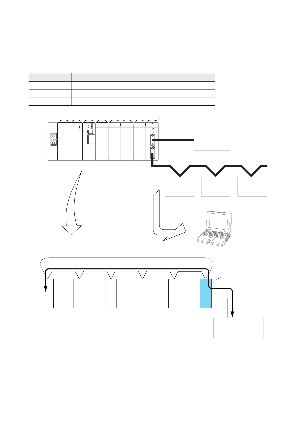
1-1 General
NP1L-RS1/2/4 are communication modules which enable data communication between a CPU module and external
devices, and which are connected to the base board (on the SX bus) of MICREX-SX series. (NP1L-RS1/2/4 are
sometimes abbreviated as RS1/2/4.)
The port type and the number of ports are as follows:
epyT stropfo.oN
1SR-L1PNlennahc1:584-SR,lennahc1:C232-SR
2SR-L1PNlennahc1:C232-SR
4SR-L1PNlennahc1:584-SR
RS1
RS-232C
Power
supply
(1:1)
CPU I/O I/O I/O I/O
RS-485
(1:n) n = Max. 31
External
device
As an external device,
it is possible to connect
a loader software
package for in a
personal computer.
<Overview of SX bus connection>
Total length of SX bus: Max. 25m
I/O I/O I/O I/O
CPU
Data transmission between CPU and an
external device is performed via the SX bus.
External
device
Loader software package for a personal computer
External
device
External
device
General purpose
communication module
External device
1-1
Page 11
1-2 Selections and Programs for the Communication
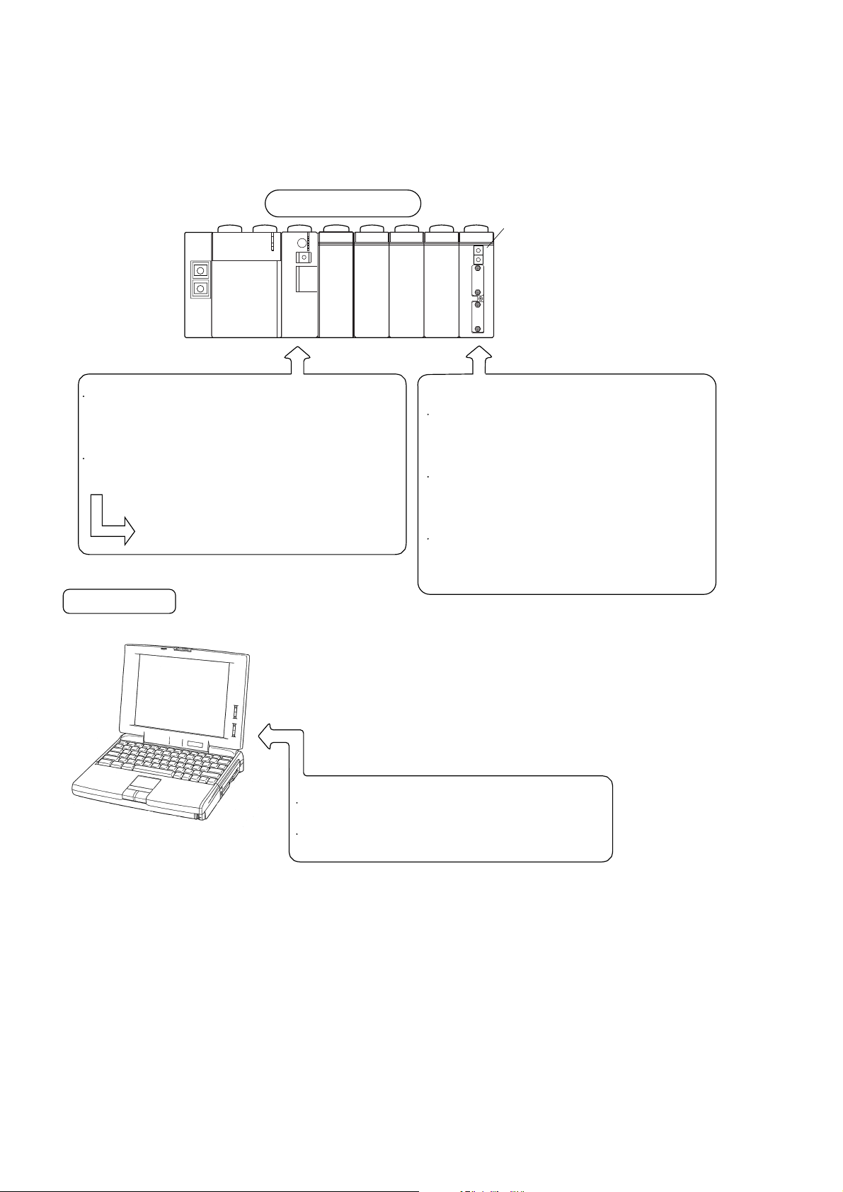
The following preparations are necessary for RS1/2/4 to communicate between a CPU module of MICREX-SX series and
external devices.
MICREX-SX series
RS1/2/4
Power
supply
<CPU modules side>
Initializing parameters for a RS-232C port and a
RS-485 port.
(Transmission speed, data length, parity bit, stop
bits etc.,)
Application software for the communication.
FA packages are optionally provided
for each external device.
External device
CPU I/O I/O I/O I/O
<RS1/2/4 side>
Selection switch of the module is used.
RS-485 station No. selection switch (0 to F)
If RS-485 port is not used, the selection is not
necessary.
Mode selection switch
Device selection of RS-232C port and RS-485
port, Data conversion
RS-485 terminating resistor ON/OFF switch
ON/OFF of terminating resistor is selected.
If RS-485 port is not used, this switch is ignored.
<External device side>
Transmission speed, data length, parity bit, stop bits etc.
Application software for the communication.
1-2
Page 12

1-3 General Purpose Communication Package
for Factory Automation Machine
Nonsequenced FB is provided for NP1L-RS1/2/4 to communicate with external serial devices. (Included in D300win.)
General purpose communication package for Factory Automation machine (NP4N-COMF) is provided to communicate
with specified external serial devices.
NP4N-COMF includes following function blocks.
erudecorP emanBF eciveD
XERkrC_ seiresRS-XERAF,D-XER,F-XER.DTL,.OCUOYGOKAKIR
erutarepmeT
rellortnoc
metsysDI
redaeredocraB
SCESSCES_C_ )ylnoI-SCESrof(metsysgnirutcafunamrotcudnocimeserudecorpSCES
XAmoC_ seiresJX5E,XA5ErellortnocerutarepmetlatigiD.noitaroproCNORMO
KCmoC_ seiresKC5ErellortnocerutarepmetlatigiD.noitaroproCNORMO
CDSmyC_ seiresG04/A04CDSrellortnocerutarepmetcinortigiD.noitaroproCekatamaY
6VmoC_seires006V.noitaroproCNORMO
SDhsC_
MAWmyC_ seires021MAWmetsysDIhsiugnitsidedoC.noitaroproCekatamaY
PFziC_ seiresA1PFmetsysreirracataD.NOITAROPROCIMUZICEDI
DCTktC_ seiresVR0023-SMLT,0058/0028DCT.dtL,.oCNEKOHT
CCBdnC_ 007LB,005LB,seires0062CCB.DTL,.OCYRTSUDNICIRTCELENOPPIN
LBykC_seires081LB.NOITAROPROCECNEYEK
SDziC_ seiresSDredaeredocraB.DTL,.OCCIGOLATADIMUZI
seiresSDmetsys
etalpDIevaworciM.NOITAROPROCMETSYSGNIRUTCAFUNAMPRAHS
Note: General purpose communication FB in the table below is included in D300win.
epyT emanBF weivrevOBF
eerf_C_)1etoN(sdrow215:evieceRsdrow215:dneSBFlarudecorp-noN
252rfC_)1etoN(sdrow252:evieceRsdrow252:dneSBFlarudecorp-noN
821rfC_)1etoN(sdrow821:evieceRsdrow821:dneSBFlarudecorp-noN
46rfC_)1etoN(sdrow46:evieceRsdrow46:dneSBFlarudecorp-noN
23rfC_)1etoN(sdrow23:evieceRsdrow23:dneSBFlarudecorp-noN
BFlarudecorp-noN
retrevnIIJUFroF
retaehIJUFroFXYPdfC_)2etoN(seiresHYPdnaseiresXYPretaehIJUFroF
edocrabIJUFroFKPdfC_)2etoN(seires2KPredaeredocrabIJUFroF
rprfC_)1etoN(
2prfC_)2etoN(
NRFdfC_)2etoN(seiresCINERFretrevnIIJUFroF
RVFdfC_)2etoN()SUB-IGF(seires11C-RVFretrevnIIJUFroF
rprvfC_)2etoN(
.eludomehthtiwgnissecorp
.eludomehthtiwgnissecorp
sdrow215:evieceRsdrow215:dneS
sdrow215:evieceRsdrow215:dneS
locotorpnoitacinummocotnitliubhcihwBFerudecorp-noN
noitacinummocehtfotrapagnimrofrepybdecudersiyticapacmargorpehT
locotorpnoitacinummocotnitliubhcihwBFerudecorp-noN
noitacinummocehtfotrapagnimrofrepybdecudersiyticapacmargorpehT
ebnacgnissecorpnoitacinummoc,noitiddanI.eludomehthtiwgnissecorp
.stropegassemsubXSowtgnisuybdeeps-hgihebam
)SUB-IGF(seires11C-RVFretrevnIIJUFroF
noitacinummocehtfotrapagnimrofrepybdecudersiyticapacmargorpehT
Note 1: Refer to Section 4 in this manual.
Note 2: For _Cfrp2, _CfdFRN, _CfdFVR, _Cfvrpr, _CfdPYX, and _CfdPK, refer to “MICREX-SX USER'S MANUAL
STANDARD EXTENDED FB (FEH255).”
1-3
Page 13

1-4 Product Versions and Supported Functions
For the general purpose communication module, supported functions and available FBs depend on the product version.
1-4-1 Supported functions
Note 2: : supported : Not supported
noisrevdnatamroF 1noitcnufredaoldesab-medoM 2noitcnufredaoldesab-medoM
1301.V1SR-L1PNnahtreilraExx
1301.V2SR-L1PNnahtreilraExx
1301.V4SR-L1PNnahtreilraE1etoN— 1etoN—
retalro1301.V1SR-L1PNox
retalro1301.V2SR-L1PNox
retalro1301.V4SR-L1PN1etoN— 1etoN—
retalro5352.V1SR-L1PNoo
retalro5352.V2SR-L1PNoo
retalro5352.V4SR-L1PN1etoN— 1etoN—
Note 1: The modem-based loader functions are functions which realize remote operation and programming by connecting
a modem to the RS-232C port and using the public circuit. These functions cannot be used with the NP1L-RS4
which is provided only with the RS-485 port.
Note 2: With modem-based function 1, the transmission rate between this module and a commercial modem is fixed to
19200 bps. With modem-based function 2, the transmission rate can be selected from 9600, 19200, and 38400
bps.
1-4-2 Available standard extended FB
emaNBF weivrevOBF
eerf_C_sdrow215:evieceRsdrow215:dneSBFlarudecorp-noN
252rfC_sdrow252:evieceRsdrow252:dneSBFlarudecorp-noN
821rfC_sdrow821:evieceRsdrow821:dneSBFlarudecorp-noN snoisrevllA
46rfC_sdrow46:evieceRsdrow46:dneSBFlarudecorp-noN
23rfC_sdrow23:evieceRsdrow23:dneSBFlarudecorp-noN
locotorpnoitacinummocotnitliubhcihwBFerudecorp-noN
rprfC_
.eludomehthtiwgnissecorp
2PRfC_
NRFdfC_seiresCINERFretrevnIIJUFroF 1etoNsnoisrevllA
RVFdfC_)SUB-IGF(seires11C-RVFretrevnIIJUFroF 1etoNsnoisrevllA
rprvfC_
.eludomehthtiwgnissecorp
XYPdfC_seiresHYPdnaseiresXYPretaehIJUFroF 1etoNsnoisrevllA
KPdfC_seires2KPredaeredocrabIJUFroF 2etoNsnoisrevllA
sdrow215:evieceRsdrow215:dneS
noitacinummocehtfotrapagnimrofrepybdecudersiyticapacmargorpehT
locotorpnoitacinummocotnitliubhcihwBFerudecorp-noN
sdrow215:evieceRsdrow215:dneS
noitacinummocehtfotrapagnimrofrepybdecudersiyticapacmargorpehT
ebnacgnissecorpnoitacinummoc,noitiddanI.eludomehthtiwgnissecorp
.stropegassemsubXSowtgnisuybdeeps-hgihebam
)SUB-IGF(seires11C-RVFretrevnIIJUFroF
noitacinummocehtfotrapagnimrofrepybdecudersiyticapacmargorpehT
eludom
retalro5352.V
retalro6352.V
noitacinummocesoprup
1etoNretalro6352.V
larenegfonoisrevelbacilppA
Note 1: This FB uses the RS-485 port. Cannot be used with the NP1L-RS2 which is provided only with the RS-232C port.
Note 2: This FB uses the RS-232C port. Cannot be used with the NP1L-RS4 which is provided only with the RS-485 port.
1-4
Page 14

Section 2 Specifications
Page
2-1 General Specifications ............................................................................................... 2-1
2-2 Communication Specifications ................................................................................. 2-2
2-3 Names and Functions................................................................................................. 2-3
2-3-1 Names ................................................................................................................................... 2-3
(1) NP1L-RS1 ............................................................................................................................................... 2-3
(2) NP1L-RS2 ............................................................................................................................................... 2-3
(3) NP1L-RS4 ............................................................................................................................................... 2-4
2-3-2 Functions .............................................................................................................................. 2-4
2-4 Dimensions.................................................................................................................. 2-7
Page 15

General specifications
metI noitacificepS
erutarepmet
egarotS
lacisyhP
latnemnorivne
snoitidnoc
lacinahceM
ecivres
snoitidnoc
lacirtcelE
ecivres
snoitidnoc
noitcurtsnoCepytdetnuom-lenaP
gnilooCgniloocriA
dohtemnoitalosIrelpuocotohP
htgnertscirtceleiD )dnuorgdnasniprotcennocO/Ineewteb(etunim1CAV544
ecnatsisernoitalusnIM01 Ω )dnuorgdnasniprotcennocO/Ineewteb(reggemCDV005htiweromro
ssaM
snoisnemiD4-2nidebircseD
erutarepmet
noitarbiV s/m6.91:noitareleccatnatsnoC,mm51.0:edutilpmaflaH
kcohSs/m741:kaepnoitareleccA
citatsortcelE
egrahcsid
dleifcite
noitpmusnoctnerruclanretnI
tneibmagnitarepO
ytidimuhevitaleRnoitasnednoconHR%59ot02
eergednoitulloP2
ytinumminoisorroC .stnevloscinagrohtiwdeniatstoN.sesagevisorrocmorfeerF
edutitlagnitarepO )eromroaPk07:noitidnoctropsnarT(levelaesevobasselrom0002
ytinummiesioN
-ngamortceleoidaR
55ot0 ° C
07+ot52- ° C
)rotalumis
:egrahcsidlaireA ± Vk8
Section 2 Specifications
2-1 General Specifications
2
2
1htdiweslup,sn1emitesir,)enilnoissimsnartotgnipmalc:Vk1(Vk5.1 µ esion(s
:egrahcsidtcatnoC ± Vk6
)zHM0001otzHM08(m/V01
sselroAm011,CDV42:1SR-L1PN
sselroAm09,CDV42:2SR-L1PN
sselroAm08,CDV42:4SR-L1PN
g071.xorppA:1SR-L1PN
g061.xorppA:2SR-L1PN
g061.xorppA:4SR-L1PN
2-1
Page 16

2-2 Communication Specifications
metI noitacificepS
C232-SR584-SR
epyT
External interface
troP
dohtem
seludom
tolsdeipuccO
1SR-L1PN
2SR-L1PN
—lennahc1
4SR-L1PN
dohtemnoitacinummoC
noitazinorhcnyS
deepsnoissimsnarT
ecnatsidnoissimsnarT
elbatcennocfo.oN
dohtemnoitcennoC
locotorpnoissimsnarT
DELnoitacidnisutatS
lennahc1lennahc1
lennahc1—
sselrom51 )sselrospbk2.91:deepsnoissimsnart(sselromk1
)ecivedlanretxeenO(1:1).xaM(13:1
)elamef(rotcennocnip-9,bus-D)elam(rotcennocnip-9,bus-D
tols1
neerG—gnidneslangiS:DXT
Communication specifications
4SR-L1PN,2SR-L1PN,1SR-L1PN
)1etoN(noitacinummocxelpud-flah
noissimsnartsuonorhcnyspots-tratS
)2etoN(spb00675/00483/00291/0069/0084/0042/0021
)3etoN()slennahc2folatotnisselrospb00675.xam,1SRrof(
.eludomUPCehtni)BF(margorpnoitacilppaehtnosdnepeD
)niw003DnidedulcnI(BFlarudecorp-noN
neerG—gninnuryllamroN:LNO
deR—eludomnoitacinummocesopruplareneG:RRE
deR—rorrenoitacinummoC:MLA
neerG—gniviecerlangiS:DXR
neerG—sisongaid-fleS:2ST,1ST
deR—rorrenoitacinummoC:MLA
neerG—gniviecerlangiS:DXR
neerG—gnidneslangiS:DXT
Note 1: The use of the non-procedural FB allows this mode to be used like the full-duplex mode on applications.
Note 2: Transmission rates 300, 600, 76800, and 115200 bps can be used in the following combinations:
esopruplarenegfonoisreV
eludomnoitacinummoc
retalro5352.V )locotorpni-tliubhtiwBFlarudecorp-noN(rprfC_
retalro6352.V
Note 3: This limitation is applied to RS1 before version V2535.
BFdednetxedradnatS
)noisrevegassem-2,locotorpni-tliubhtiwBFlarudecorp-noN(2prfC_
)locotorpni-tliubhtiwBFerudecorpretrevnI(rprvfC_
2-2
Page 17
Names and functions
2-3-1 Names
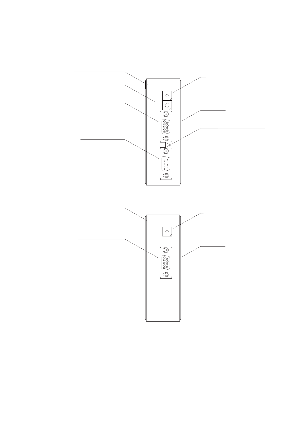
(1) NP1L-RS1
1) Status indication LED
3) RS-485 station No. selection switch
4) RS-232C port
(D-sub, 9-pin, female)
6) RS-485 port
(D-sub, 9-pin, male)
ONL
ERR
RS232C
RS485
TERM.
RS485
No.
(0-F)
RS232 TS1
ALM RXD TXD
RS485
7
6
5
MODE
4
B
A
9
8
7
6
1-2-3
2-3 Names and Functions
2) Mode selection switch
TS2
8
9
0
1
2
3
c
D
E
F
0
1
2
3
5
4
Nameplate
5) RS-485 terminating resistor
ON-OFF switch
(2) NP1L-RS2
1) Status indication LED
4) RS-232C port
(D-sub, 9-pin, female)
RS485
ONL
ERR
RS232C
RS232 TS1
ALM RXD TXD
7
6
5
MODE
4
2) Mode selection switch
TS2
8
9
0
1
2
3
Nameplate
2-3
Page 18
2-3 Names and Functions
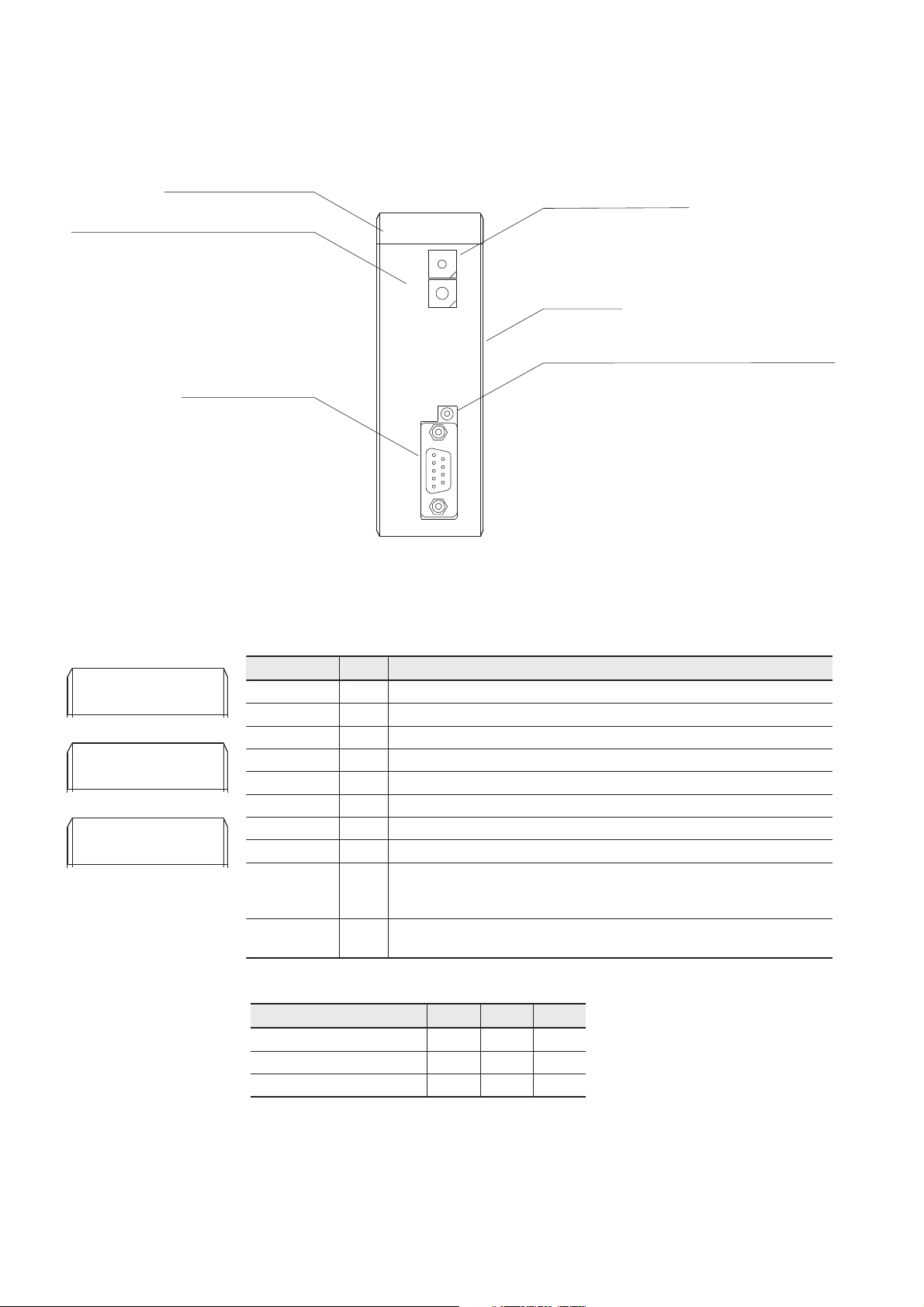
(3) NP1L-RS4
1) Status indication LED
3) RS-485 station No. selection switch
6) RS-485 port
(D-sub, 9-pin, male)
ONL
ALM RXD TXD
ERR
MODE
RS485
No.
(0-F)
RS485
TERM.
RS485
1-2-3
RS485
Names and functions
2) Mode selection switch
TS1
TS2
8
7
9
6
0
5
1
4
2
3
c
D
B
E
A
F
9
0
8
1
7
2
6
3
5
4
Nameplate
5) RS-485 terminating resistor ON-OFF switch
2-3-2 Functions
1) Status indication LED
This LED indicates the running status of NP1L-RS1/2/4.
NP1L-RS1
ONL
ALM RXD TXD
ERR
NP1L-RS2
ONL
ALM RXD TXD
ERR
NP1L-RS4
ONL
ALM RXD TXD
ERR
RS232 TS1
RS485
RS232 TS1
RS485
TS2
TS2
TS1
TS2
lobmyS roloC noitpircseD
LNOneerG .subXSehthtiwetacinummocotydaersieludomehtnehwnosnruT
RREdeR.lamronbasieludomehtnehwnosnruT
MLAC232SRdeR.lamronbasiC232-SRaivatadnoitacinummocehtnehwnosnruT
DXRC232SRneerG.atadgniviecersitropC232-SRehtnehwnosnruT
DXTC232SRneerG.tropC232-SRehtmorftnesgniebsiatadnehwnosnruT
MLA584SRdeR.lamronbasi584-SRaivatadnoitacinummocehtnehwnosnruT
DXR584SRneerG.atadgniviecersitrop584-SRehtnehwnosnruT
DXT584SRneerG.trop584-SRehtmorftnesgniebsiatadnehwnosnruT
1STneerG
2STneerG
eludomfotluaflataFFFONO —
eludomfotluaflatafnoNNONO —
rorreataDNOFFONO
.7edomsisongaid-flesnidetcetedsirorreMARlanretninehwsknilB
sisongaid-flesnilamronbasitsetkcabgninrutC232-SRnehwsknilB
)rorrekcab-gninrutSTC-TSR(.8edom
sisongaid-flesnilamronbasitsetkcabgninrutC232-SRnehwsknilB
)rorrekcab-gninrutRSD-RTD(.8edom
sutatseludomybsutatsDELfoelpmaxE*
LNO RRE MLA
2-4
Page 19

Functions
2-3 Names and Functions
2) Mode selection switch
This switch is used to select a connectable device, the signal conversion and the self-diagnosis for the RS-232C port and
the RS-485 port.
C
MODE
D
B
E
A
F
9
8
7
6
3
5
4
Switch
0
1
2
No.
Mode
RS-232C port RS-485 port
RS-232C <=> RS-485
Signal conversion
Remarks
0 General purpose device General purpose device Not available
1 Programming loader General purpose device Not available
2 General purpose device Programming loader Not available
3 Programming loader Programming loader Not available
Applies to
V2535 or later.
4 General purpose device General purpose device Available
5
Not used
6
Modem-loder
19200 bps
General purpose device Not available
Applies to
V1031 or later.
7 Self-diagnosis mode 1 (diagnoses internal memory and LED)
8 Self-diagnosis mode 2 (diagnoses RS-232C, RS-485 turning back)
Modem-loder
9
19200 bps
Modem-loder
A
9600 bps
Modem-loder
B
9600 bps
Modem-loder
C
38400 bps
Modem-loder
D
38400 bps
Modem-loder
E
76800 bps
(Note 5)FModem-loder
115200 bps
Programming loader Not available
General purpose device Not available
Programming loader Not available
General purpose device Not available
Programming loader Not available
General purpose device Not available
Modem-loder
115200 bps
—
Applies to
V1031 or later.
Applies to
V2535 or later.
Applies to
V2536 or later.
Note 1: For details of the function mode, refer to “3-2 System configuration.”
Note 2: For the self-diagnosis, refer to “3-4 Self-diagnosis.”
Note 3: “Programming loader” is the mode for connecting to D300win. Communication specifications are fixed to” 38400
bps” for transmission speed, “8 bits” for data length, “1 bit” for stop bits, and “even” for parity.
Note 4: “Modem-loader" is the mode that is basically used to connect to D300win loader via a modem. In general, for
modems, “none” is specified for parity. Therefore, in this mode, communication specifications become “8 bits” for
data length, “1 bit” for stop bits, and “none” for parity.
Note 5: Either channel is selected and used.
3) RS-485 station No. selection switch
This switch used to select a RS-485 station number of NP1L-RS1 or NP1L-RS4. Selecting range is 0 to F.
C
D
B
E
A
RS485
No.
(0-F)
F
9
0
8
1
7
2
6
3
5
4
2-5
Page 20
2-3 Names and Functions
Functions
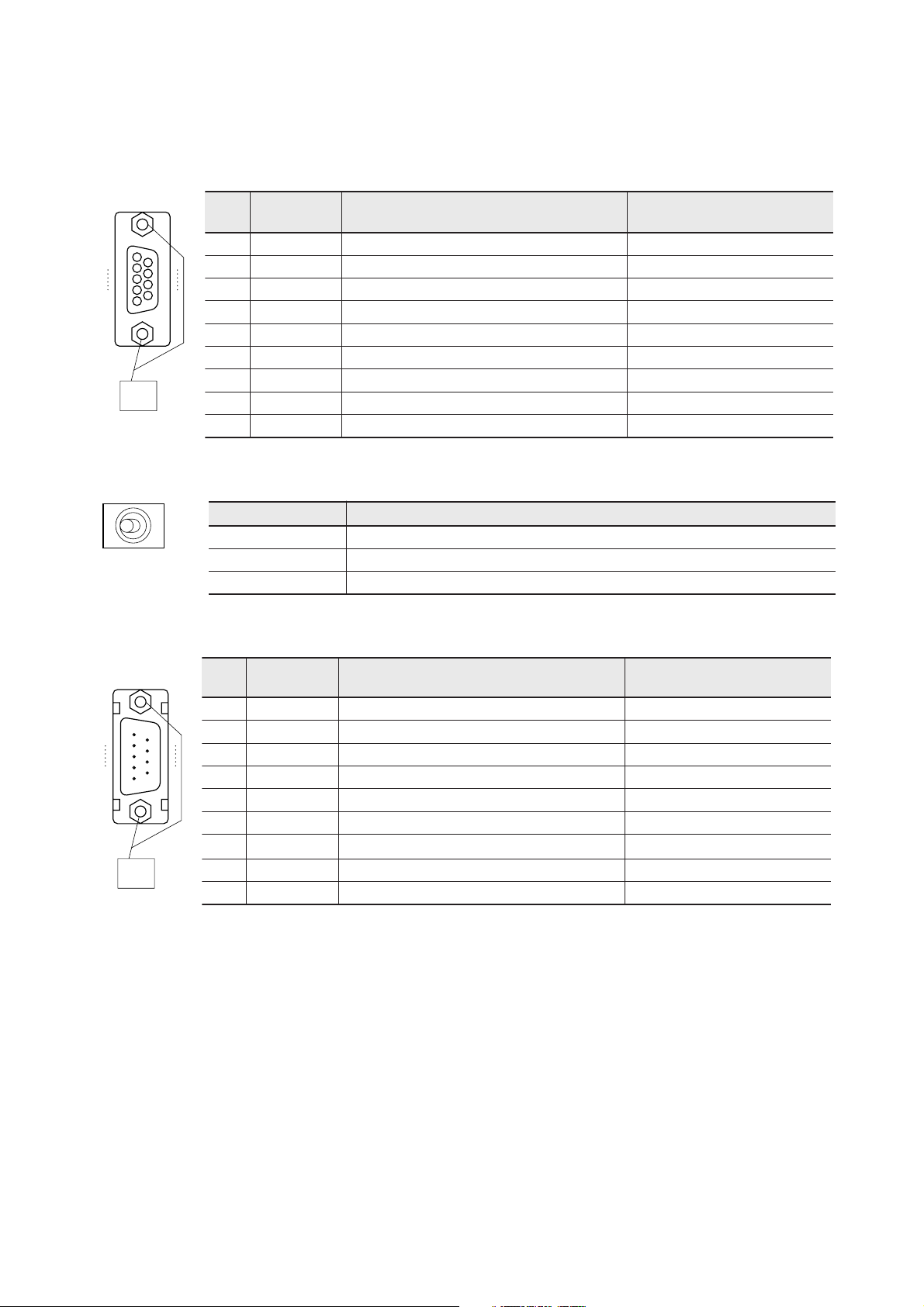
4) RS-232C port
This port is D-sub, 9-pin connector (female). This connector is connected to D-sub, 9-pin connector (male).
niP
.oN
1
5
6
9
1DC==<tcetedreirraC
2DR==<atadevieceR
3DS>==ataddneS
4RE>==ydaerlanimretataD
emanlangiS ecivedlanretxeot2/1SRnoitceridlangiS noitpircseD
5GS )nruternommoc(dnuorglangiS
6RD==<ydaertesataD
M2.6
Screw
7SR>==dnesottseuqeR
8SC==<dnesotraelC
9IR==<noitacidnillaC
5) RS-485 terminating resistor ON/OFF switch
This switch used to select the ON/OFF of the RS-485 terminating resistor. There are three positions for this switch.
noitisophctiwS sutatS
tfeL.elbaliavasirotsisergnitanimreT,epyteriw-2
retneC.elbaliavatonsirotsisergnitanimreT
thgiR.elbaliavasirotsisergnitanimreT,epyteriw-4
6) RS-485 port
This port is D-sub, 9-pin connector (male). This connector is connected to D-sub, 9-pin connector (female).
niP
.oN
emanlangiS ecivedlanretxEot4/1SRnoitceridlangiS noitpircseD
1BDS>==)-(enillangisataddneS
5
9
2ADS>==)+(enillangisataddneS
3)BDS(>==))-(enillangisataddneS(
1
6
4)ADS(>==))+(enillangisataddneS(
5GS )nruternommoc(dnuorglangiS
6GFdnuorgemarF
7
M2.6
Screw
8BDR==<)-(BenillangisatadevieceR
9ADR==<)+(AenillangisatadevieceR
Note: For wiring, refer to “6-2 Wiring.”
2-6
Page 21
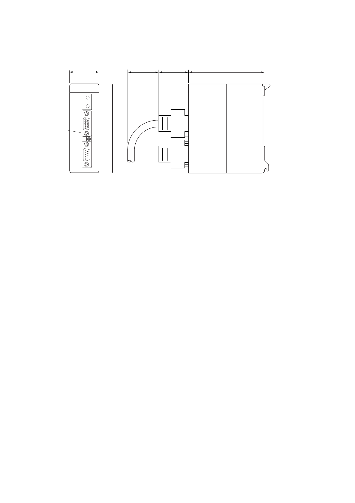
Dimensions
Dimensions are same for NP1L-RS1,NP1L-RS2 and NP1L-RS4.
35
(90)
(37)
2-4 Dimensions
90
(Note)
105
Note: Front formation depends on each type.
2-7
Page 22

Section 3 System Configuration
Page
3-1 Mounting Restrictions ................................................................................................ 3-1
3-1-1 Mounting position .................................................................................................................. 3-1
3-1-2 Number of mountable modules ............................................................................................. 3-1
3-2 System Configurations............................................................................................... 3-2
3-2-1 1:1 Connection using RS-232C port ..................................................................................... 3-2
3-2-2 1:N Connection using RS-485 port (N = max. 31 modules) .................................................. 3-3
3-2-3 Connecting independently to RS-232C and RS-485 ports ................................................... 3-4
3-2-4 Connection using RS-232C and RS-485 ports (2) ................................................................ 3-5
3-2-5 Connecting a personal computer loader to the RS-232C port and RS-485 port .................. 3-7
3-2-6 Loader network configuration using RS-485 ......................................................................... 3-7
3-2-7 Loader network configuration using modems (1) .................................................................. 3-8
3-3 Loader Connecting Cable .......................................................................................... 3-9
3-3-1 When connecting to RS-232C port ....................................................................................... 3-9
3-3-2 When connecting to RS-485 port .......................................................................................... 3-9
3-4 Self-diagnosis ........................................................................................................... 3-10
3-4-1 Self-diagnosis mode 1 ........................................................................................................ 3-10
3-4-2 Self-diagnosis mode 2 ........................................................................................................ 3-11
(1) RS to CS signal check .......................................................................................................................... 3-11
(2) ER to DR signal check .......................................................................................................................... 3-11
(3) RS-232C/RS-485 data check................................................................................................................ 3-11
(4) Preservation of the result of the check.................................................................................................. 3-11
Page 23

Mounting restrictions
Section 3 System Configuration
3-1 Mounting Restrictions
3-1-1 Mounting position
NP1L-RS1/2/4 is a general purpose communication module which is connected to the SX bus of MICREX-SX series. The
mounting position on the base board is restricted as follows:
They can be mounted in any slot except those for the power supply module (the two slots from the left on the base board).
<Base board other than 6-slots base board>
<6-slots base board>
Mountable slots
Note: The general purpose communication modules cannot be mounted on T-link or OPCN-1 slave station base boards.
Power
supply
T-link master module
CPU
Mountable slots
T-link interface module
I/O I/O I/O I/O
Power
supply
3-1-2 Number of mountable modules
A maximum of 16 modules per configuration can be connected. However, when other communication related modules are
used in the same configuration, the maximum number of 16 is the total of these and NP1L-RS1/2/4 modules.
P-link module (NP1L-PL1)
PE-link module (NP1L-PE1)
FL-net (OPCN-2) module (NP1L-FL1)
General purpose communication module (NP1L-RS1/2/4)
PC card interface module (NP1F-PC2)
Memory card interface module (NP1F-MM1)
Maximum of 16 modules per configuration.
3-1
Page 24
3-2 System Configurations
3-2-1 1:1 Connection using RS-232C port
This configuration connects to an external device having an RS-232C interface via the RS-232C port.
The mode selection switch is set to “0” (zero).
RS1 or RS4
<Mode selection switch: “0”>
RS-232C port
1: 1 connection
General purpose device
Power
supply
CPU
RS-485 port
Signal conversion
General purpose device
None
RS-232C
External device
* With RS1, a D300win personal computer loader can be connected to an RS-485 port which is not used.
In this case, the mode selection switch needs to be set to “2.”
RS1
<Mode selection switch: “2”>
General purpose device
Loader
None
Power
supply
CPU
RS-485
RS-232C port
RS-485 port
Signal conversion
RS-232C
External device
For the connection, refer to “3-3-2 When
connecting to RS-485 port.”
3-2
Page 25

1: N connection
3-2 System Configurations
3-2-2 1:N Connection using RS-485 port (N = max. 31 modules)
This configuration connects to external devices having an RS-485 interface via the RS-485 port. The mode selection
switch is set to “0.” A maximum of 31 external devices can be connected. However, when all external devices are RS1 or
RS4, the maximum number is limited to 15 because only 0 to F are available for addressing.
RS1 or RS4
<Mode selection switch: “0”>
Power
supply
CPU
RS-232C port
RS-485 port
Signal conversion
RS-485
General purpose device
General purpose device
None
External device External device External device
ABC
Note: External devices A , B and C must be the same in type as well
as communication protocol. For example, this connection is not
available when A and B are temperature controllers and C is a
bar code reader.
* With NP1L-RS1, a D300win personal computer loader can be connected to an RS-232C port which is not in use.
In this case, the mode selection switch needs to be set to “1.”
RS1
<Mode selection switch: “1”>
Loader
General purpose device
None
Power
supply
CPU
RS-232C
RS-232C port
RS-485 port
Signal conversion
RS-485
External device External device External device
ABC
For the connection, refer to “3-3-1 When
connecting to RS-232C port.”
3-3
Page 26
3-2 System Configurations
1: 1 / 1: N connection
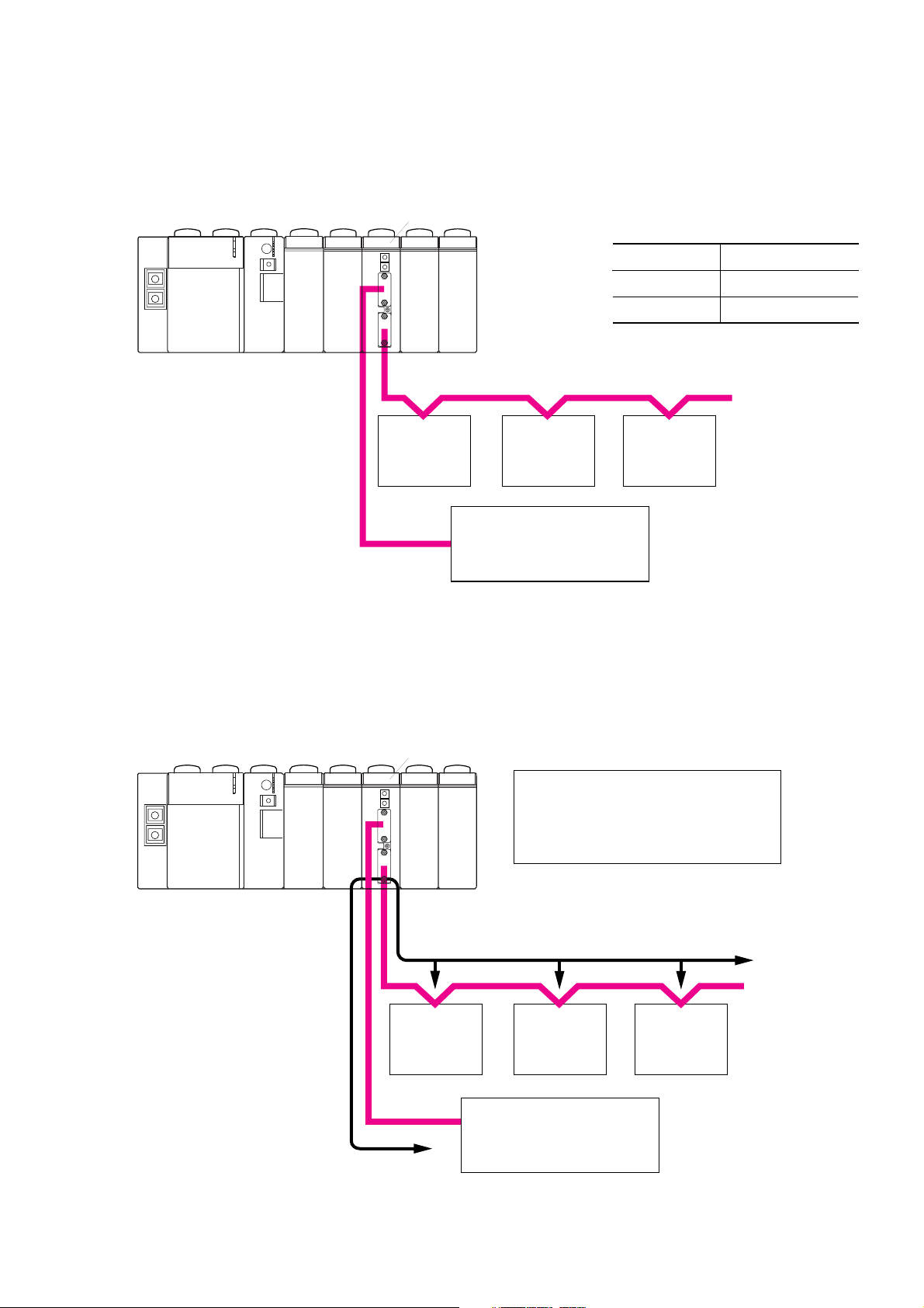
3-2-3 Connecting independently to RS-232C and RS-485 ports
This configuration connects to external devices using the RS-232C port and RS-485 port. In this case, communication
through these ports is performed independently.
Power
supply
RS1
CPU
RS-485
<Mode selection switch: “0”>
RS-232C port
RS-485 port
Signal conversion
General purpose device
General purpose device
None
External device
ABC
Note: External devices A , B and C must be the same in type as well
as communication protocol. For example, this connection is not
available when A and B are temperature controllers and C is a
bar code reader.
RS-232C
External device External device
External device
3-4
Page 27
1: 1 / 1: N connection
3-2 System Configurations
3-2-4 Connection using RS-232C and RS-485 ports (2)
This configuration connects to external devices using the RS-232C port and RS-485 port.
RS1
Power
supply
CPU
External device
External device External device
BCD
RS-232C
External device
(personal computer, etc.)
With this configuration, the following communications can be performed :
1) Communication between external device A and external device B, C or D (not via the CPU module)
2) Communication between external device A and CPU module
3) Communication between external device B, C or C and CPU module
<Mode selection switch: “0”>
RS-232C port
RS-485 port
Signal conversion
RS-485
A
General purpose device
General purpose device
Yes
<1) Communication between external device A and external device B, C or D>
This communication is performed directly, namely not via the CPU module.
RS1
Transmission speed is 38400 bps (default) for
both RS-232C and RS-485. Changing
transmission speed is done through the user
Power
supply
CPU
program (expansion FB).
RS-485
External device
External device External device
BCD
RS-232C
External device
(personal computer, etc.)
A
3-5
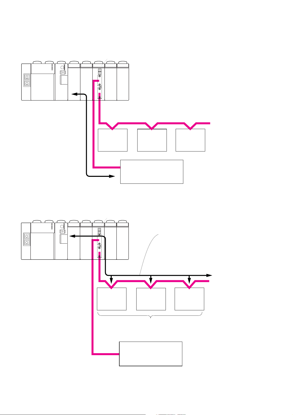
Page 28
3-2 System Configurations
<2) Communication between external device A and the CPU module>
RS1
1: 1 / 1: N connection
Power
supply
CPU
RS-485
External device
B
External device External device
C
RS-232C
External device A
(personal computer, etc.)
(Note)
<3) Communication between external device B, C or D and the CPU module>
RS1
D
Note: A user program for
controlling external
device A is necessary.
Power
supply
CPU
Note: When the station number designated in the
send data is the same as the setting of the
RS-485 station number setting switch of RS1,
FB in the CPU module receives the data.
RS-485
External device
External device External device
BCD
Note: External devices A, B and C must be the same in type as well as
communication protocol. For example, this connection is not available
when A and B are temperature controllers and C is a bar code reader.
RS-232C
External device A
(personal computer, etc.)
3-6
Page 29
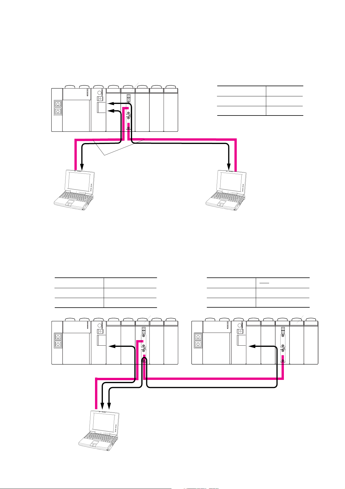
1: 1 / 1: N connection
3-2 System Configurations
3-2-5 Connecting a personal computer loader to the RS-232C port and RS-485 port
This configuration connects a D300win personal computer loader to each of RS-232C and RS-485 ports.
Power
supply
RS1
CPU
RS-232C
<Mode selection switch: “3”>
RS-232C port
RS-485 port
Signal conversion
RS-485
Loader
Loader
None
For the connection, refer to
“3-3 Loader Connecting Cable.”
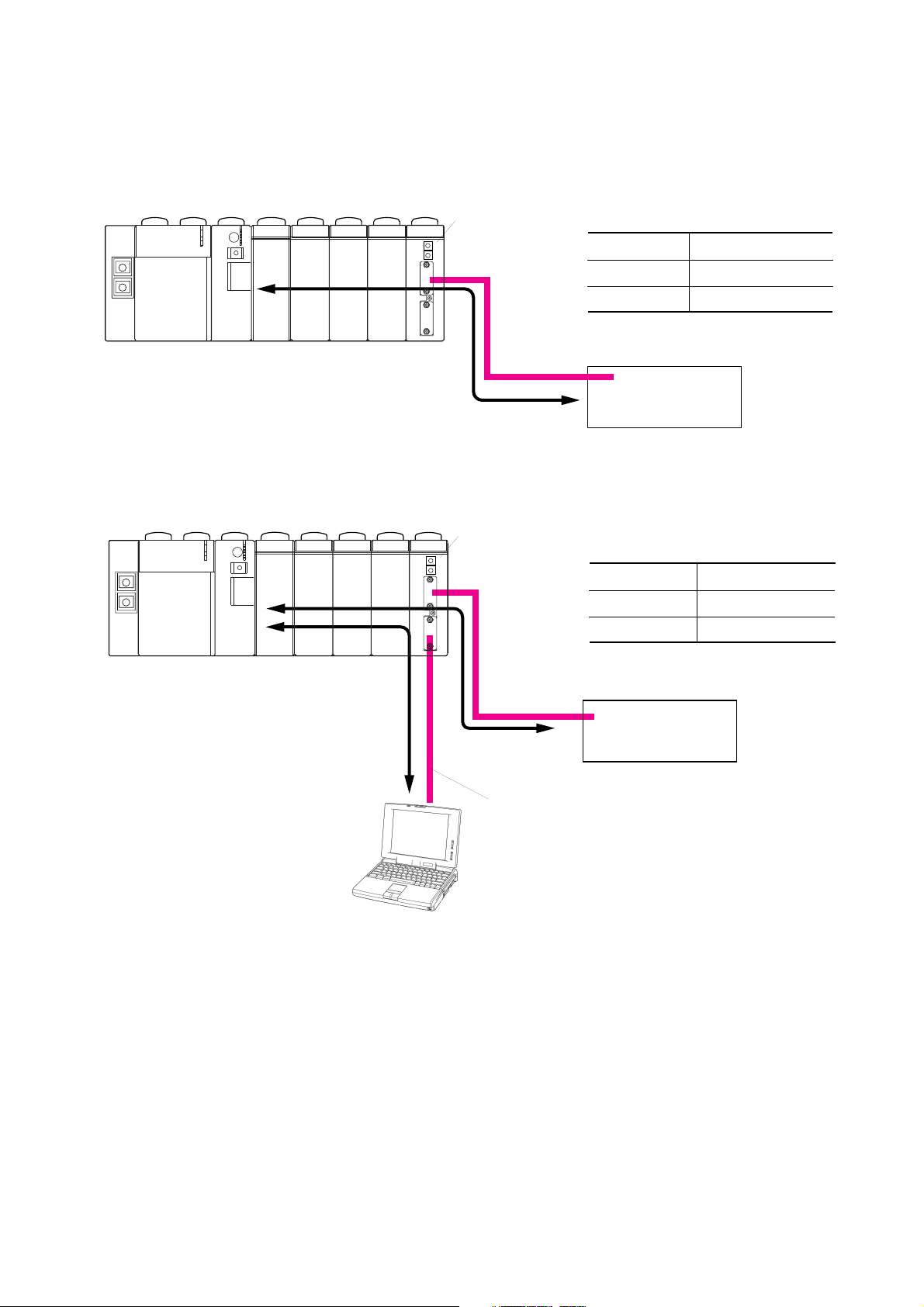
3-2-6 Loader network configuration using RS-485
This configuration connects a D300win personal computer loader to the RS-232C port of RS1 on System 1.
A D300win can communicate with both CPUs of System 1 and System 2.
<Mode selection switch of System 1: “5”>
RS-232C port
RS-485 port
Signal conversion
Power
supply
Loader
General device/loader
Yes
CPU
RS-232C
<Mode selection switch of System 2: “2”>
RS-232C port
Loader
Normal
RS1
RS1
RS-485 port
Signal conversion
Power
supply
CPU
RS-485
• When connected to the CPU of System 1, designate, from the
programming loader, the CPU which is in the configuration.
• When connected to the CPU of System 2, designate, from the
programming loader, the RS-485 station number of RS1 on System 2.
3-7
Page 30

3-2 System Configurations
Modem connecting
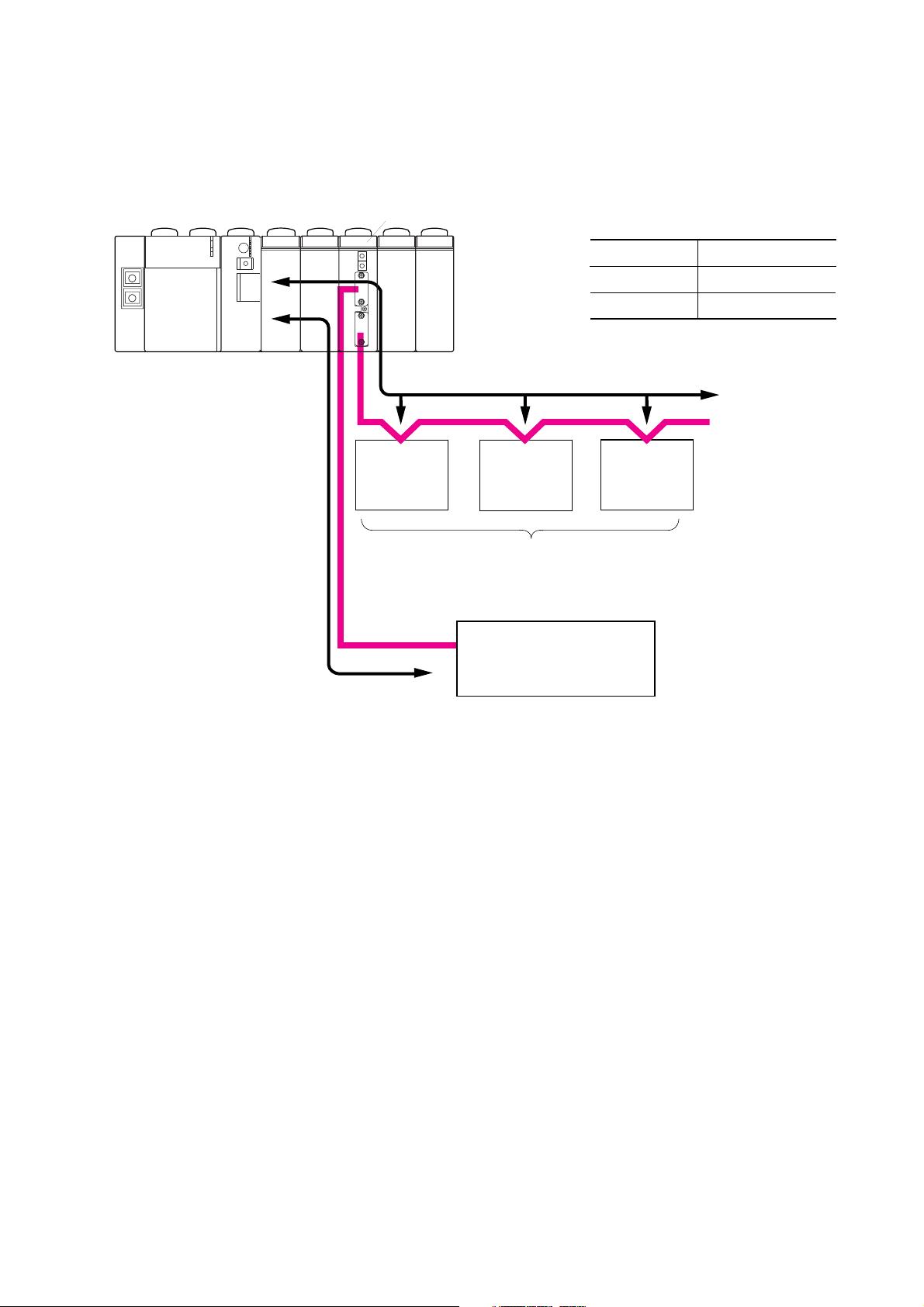
3-2-7 Loader network configuration using modems (1)
This configuration enables remote programming using the public circuit by connecting a modem to the RS-232C port.
RS1 or RS2
When the NP1L-RS1 is used and the mode
Power
supply
CPU
selection switch is set to 6, A, or C,
general purpose devices can be
connected to the RS-485 port.
RS-232C
Straight
cable
External device
*
Modem
Modem
Set with
D300win.
RS-485
External device External device
ABC
Modem setup is made using "WINDOWS Hyper Terminal and
other application software" with the following communication mode:
Stop bit: 1 Data length: 8 bits Parity: None
Baud rate: 9600/19200/38400/76800/115200
(set by the mode selection switch of this module)
Issue AT commands to perform the following:
Restore the setup of the current value area to "Factory Setup."
Do not perform the flow control.
Set the number of rings until automatic receive of the modem to 3.
Do not return the response code.
Write the current modem setup condition to PROFILE(1).
Use the contents of PROFILE(1) as the setup used when the power
is turned ON.
Example: AT&F&K0S0=3Q1&W0&Y0
Note: For details, refer to the instruction manual supplied
with the modem used.
3-8
Page 31

Loader connecting
To connect a D300win personal computer loader to the RS-232C or RS-485 port of the general purpose communication
module, the cable must be connected in the following manner.
3-3 Loader Connecting Cable
3-3-1 When connecting to RS-232C port
Because the RS-232C connector of the general purpose communication module is “female,” attach the male connector
onto the cable connector for the general purpose communication module, as shown in the figure below:
General purpose communication module side Personal computer side
9-pin D-sub connector (male) 9-pin D-sub connector (female.)
CD
RD
SD
ER
SG
DR
RS
CS
RI
1)
2)
3)
4)
5)
6)
7)
8)
9)
1)
2)
3)
4)
5)
6)
7)
8)
9)
CD
RD
SD
ER
SG
DR
RS
CS
RI
3-3-2 When connecting to RS-485 port
Because the RS-485 connector of the general purpose communication module is “male,” attach the female connector onto
the cable connector for the general purpose communication module, as shown in the figure below:
General purpose communication module Personal computer side
9-pin D-sub connector (female) 9-pin D-sub connector (female)
SDB
SDA
(SDB)
(SDA)
SG
FG
RDB
RDA
1)
2)
3)
4)
5)
6)
7)
8)
9)
RS-485/RS-232C converter
RXRX+
TXTX+
1)
2)
3)
4)
5)
6)
7)
8)
9)
CD
RD
SD
ER
SG
DR
RS
CS
RI
For conversion from RS-232C to RS-485
port on personal computer, use a
commercially available converter.
3-9
Page 32

3-4 Self-diagnosis
3-4-1 Self-diagnosis mode 1
Setting the mode selection switch of the module to “7” activates Self-diagnosis Mode “1.”
This mode is used to check the internal memory and the lighting condition of LEDs.
<Diagnosis flow>
Start Set the mode selection switch to “7.”
Check the internal
memory of general
purpose communication
module.
Self-diagnosis
Normal?
Yes
Repeat Self-diagnosis
Mode operations when
there is no change in the
status of the mode
selection switch.
1) Internal memory check
After the completion of LED lighting check, automatically returns to the diagnosis of the internal memory of general
purpose communication module.
If an internal memory error is detected, “TS1” blinks.
2) LED lighting check
Of the external LEDs of the module, the lighting condition of those operated by the general purpose communication
module are checked. When the mode selection switch is set to “7,” “TS1,” “TS2,” “RS-485 ALM” and “RS-232C ALM” LEDs
light up in this order.
<Normal lighting condition of LEDs>
TS1
TS2
Check the lighting
of LEDs.
No
TS1 blinks (0.25s)
Continue to blink if RAM error
is detected, and the check of
LED lighting condition will not
be executed.
RS485 ALM
RS232C ALM
1s
1s 10s
1s
1s
3-10
Page 33

Self-diagnosis
3-4 Self-diagnosis
3-4-2 Self-diagnosis mode 2
This mode is used to check the completeness of communications by looping back sent data and control signals via the
communication port.
(1) RS to CS signal check
In this check, the general purpose communication module turns RS signal ON to check whether CS signal is looped back
and turns ON, and then checks that this signal turns OFF.
When normal, “TS2” lights up; proceeds to step (2).
If abnormal, “TS2” blinks (at 0.5-second intervals) after 5 seconds; proceeds to step (2).
(2) ER to DR signal check
In this check, the general purpose communication module turns ER signal ON to check whether DR signal is looped back
and turns ON, and then checks that this signal turns OFF.
When normal, “TS1” lights up; proceeds to step (3).
If abnormal, “TS1” blinks (at 0.5-second intervals) after 5 seconds; proceeds to step (3).
(3) RS-232C/RS-485 data check
The general purpose communication modules sends 16 bytes of data once and checks the looped back data received.
If both ports are normal, “RS-232C ALM” and “RS-485 ALM” light up; proceeds to step (4).
If RS-485 is abnormal, “RS-232C ALM” lights up after 10 seconds and “RS-485 ALM” blinks (at 0.5-second intervals);
proceeds to step (4).
If RS-232C is abnormal, “RS-232C ALM” blinks (at 0.5-second intervals) after 10 seconds and “RS-485 ALM” lights up (at
0.5-second intervals); proceeds to step (4).
If both ports are abnormal, “RS-232C ALM” and “RS-485 ALM” blinks (at 0.5-second intervals); proceeds to step (4).
(4) Preservation of the result of the check
After 10 seconds of displaying the results from (3) above, the module returns to step (1). Here, if the setting of the mode
selection switch has been changed, Self-diagnosis Mode 2 is ended to enter the designated mode.
Note 1: When an RS-232C dedicated module (NP1L-RS2) is used, “RS-485 ALM” is kept turned off. When an RS-485
dedicated module (NP1L-RS4) is used, “RS-232C ALM,” “TS1” and “TS2” are kept turned off.
Note 2: When judged as “normal,” the next operation is started without any waiting time. Therefore, after all LEDs have
turned off at the start of diagnosis, the corresponding LED lights up instantaneously.
<RS-232C loop-back connector>
Pin No.
CD
RD
SD
ER
SG
DR
RS
CS
1)
2)
3)
4)
5)
6)
7)
8)
9)RI
<RS-485 loop-back connector>
Pin No.
SDB
SDA
(SDB)
(SDA)
SG
FG
RDB
RDA
1)
2)
3)
4)
5)
6)
7)
8)
9)
3-11
Page 34

Section 4 Software Interface
Page
4-1 General......................................................................................................................... 4-1
4-2 Specifications for Non-procedural FB ...................................................................... 4-3
4-2-1 Communication specification ................................................................................................ 4-3
4-2-2 FB format .............................................................................................................................. 4-4
4-2-3 FB terminals .......................................................................................................................... 4-5
4-3 Initialization ................................................................................................................. 4-7
4-3-1 Initialization parameters ........................................................................................................ 4-7
4-3-2 Initialization procedure ........................................................................................................ 4-10
4-3-3 OPEN status list .................................................................................................................. 4-10
4-4 Data Sending ............................................................................................................. 4-11
4-4-1 Data sending procedure ...................................................................................................... 4-11
4-4-2 Send status list .................................................................................................................... 4-12
4-5 Data Receiving .......................................................................................................... 4-13
4-5-1 Data receiving procedure .................................................................................................... 4-13
4-5-2 Receiving status list ............................................................................................................ 4-14
4-6 RAS Information........................................................................................................ 4-15
Page 35

Section 4 Software Interface
4-1 General
The non-procedural FB supplied with the D300wind is used for communication between the NP1L-RS1/2/4 and external
devices. The non-procedural FB performs data communication between the CPU module and external devices based on
the start-stop synchronous transmission protocol.
The following seven types of non-procedural FBs are offered.
emaNBF weivrevOnoitacificepS
eerf_C_sdrow215:evieceR,sdrow215:dneSBFlarudecorp-noN
252rfC_sdrow252:evieceR,sdrow252:dneSBFlarudecorp-noN
821rfC_sdrow821:evieceR,sdrow821:dneSBFlarudecorp-noN
46rfC_sdrow46:evieceR,sdrow46:dneSBFlarudecorp-noN
23rfC_sdrow23:evieceR,sdrow23:dneSBFlarudecorp-noN
rprfC_
2prfC_
.deepsgnissecorpehtesaercniotdesuera
sdrow215:evieceR,sdrow215:dneSBFlarudecorp-noN
.eludomehtnierawmrifehtybdessecorpsignissecorpnoitacinummocfotrapA
sdrow215:evieceR,sdrow215:dneSBFlarudecorp-noN
sdraobegassemowtdnaeludomehtnierawmrifehtybdessecorpsignissecorpnoitacinummocfotrapA
Note 1: _Cfrpr FB can be used with V.2535 or later versions of the NP1L-RS1, JP1L-RS2, and NP1L-RS4. The functions
of the non-procedural FB are shown below.
Note 2: _Cfrp2 FB can be used with V.2536 or later versions of the NP1L-RS1, JP1L-RS2, and NP1L-RS4. For the
specifications of _Cfrp2, refer to “EXTENDED FB FOR COMMUNICATION USER’S MANUAL FH255.”
1) Initialization of communication ports
Initializes RS-232C and RS-485 ports (sets transmission speed, data bit length, parity bits, etc., so as to match the
external device.)
2) Data sending/receiving function
Sends the data from an application program in the CPU of MICREX-SX series via RS1 to an external device, or outputs
the data received via the general purpose communication module to an application program.
3) Monitoring of transmission condition
Monitors the condition of data transmission and, if abnormal, outputs error information.
<Function diagram of Non-procedural FB>
CPU module RS1/2/4
Application program
Non-procedural
FB
1)
External device
2) 3)
4-1
Page 36

4-1 General
<FB operating conditions>
System configuration:
One FB is necessary for each external device which is connected by RS-232C or RS-485 to one general purpose
communication module. However, when RS-232C/RS-485 signal conversion is enabled (the mode selection switch is set
to 4) for the general purpose communication module, each FB is used by two channels.
Processor
Non-procedural
FB
for RS-232C
Non-procedural
FB
for RS-485
Processor
Non-procedural
FB
for both channels
General purpose
communication
module
(normal mode)
General purpose
communication
module
(conversion mode)
External device
connected to
RS-232C
External device
connected to
RS-485
External device
connected to
RS-232C
External device
connected to
RS-485
* When used in RS-232C/RS-485 conversion mode, channel number for the parameter (PARA [1]) is 1 (= RS-485).
Memory capacity:
emaNBF
eerf_C_6562sdrow204sdrow6563sdrow0sdrow28
252rfC_7572sdrow474sdrow4712sdrow0sdrow28
821rfC_7572sdrow474sdrow6881sdrow0sdrow28
46rfC_7572sdrow474sdrow8571sdrow0sdrow28
23rfC_7572sdrow474sdrow2761sdrow0sdrow28
rprfC_0911sdrow221sdrow8061sdrow0sdrow28
Note 1: The above memory capacity includes that of non-procedural FB itself as well as of the sub-FB which is called
from non-procedural FB.
Note 2: “Standard memory” or “Retain memory” includes the memory capacity necessary for data transmissin.
yticapacmargorP
)petS(
yromemecnatsnI
BFresurof
yromemdradnatS yromemniateR
metsysrof
4-2
yromemecnatsnI
Page 37

4-2-1 Communication specification
metI noitacificepS
deepsnoissimsnarT
stibataD
tibytiraP
stibpotS
ECD
lortnoclangiS
wolflangiS
lortnoc
lortnocFFOX/NOX
edom584-SR
noisrevnocedoC
noitcetedemarF
ytiraplatnoziroH
)CCB(
edomETD
edomECD
edomETD
edomECD
enoN
htgneldexiF
htgnelelbairaV
enoN
eulavremitnoissimsnarT
4-2 Specifications for Non-procedural FB
)etoN(spb00675/00483/00291/0069/0084/0042/0021
stib8/7morfdetceleS
neve/ddo/enoN
stib2/1morfdetceleS
edomETDmedom/ECD/ETDmorfdetceleS
gniviecernehwNODCnruT:edomETDmedoM
NOsyawla:RE
NOsyawla:RD
lanoitidnocnu:gnidneS;NOsyawla:SRffO
NOsiSCnehw:gnidneS;gnidnesgnirudNO:SRnO
lanoitidnocnu:gnidneS;NOsyawla:SCffO
NOsiREnehw:gnidneS;NOsiSRnehwNO:SCnO
elbatceleS
eriw-2/eriw-4morfdetceleS
noisrevnocCIDCBE/noisrevnocIICSA/enoNmorfdetceleS
).elbairavgnirtsretcarahcotniatadyranibtrevnoC(
.noitcnufnoitcetedemarfelbasiD
setybatadeviecerforebmunehtetangiseD
.sedocdnednatratsetangiseD
enoN
redrorewoL/redroreppU
redroreppU/redrorewoL
sm01x
.noitisopetangiseD.noitangisedegnarnoitaluclaC
CRC/ROE/trevnidnadda/ddamorfdetceleS:alumroF
edocyranib/edocretcarahcmorfdetceleS:edocCCB
Note: Transmission rates 300, 600, 76800, and 115200 bps can be used in the following combinations:
noitacinummocesopruplarenegfonoisreV
eludom
retalro5352.V )locotorpni-tliubhtiwBFlarudecorp-noN(rprfC_
retalro6352.V )noisrevegassem-2,locotorpni-tliubhtiwBFlarudecorp-noN(2prfC_
BFdednetxedradnatS
4-3
Page 38

4-2 Specifications for Non-procedural FB
4-2-2 FB format
Input terminal name Output terminal name
Open
Send request
Send data length
Send data
Receive data
Communication parameter
(BOOL) OPEN
(BOOL) S_REQ
(INT) S_LEN
(_C_SND_TYP11) S_DAT
(_C_RCV_TYP11) R_DAT
(_C_PAR_TYP11) PARA
_C_free
(Note 1)
(BOOL) OK
(WORD) O_STS
(BOOL) S_END
(BOOL) S_ERR
(WORD) S_STS
(BOOL) R_END
(BOOL) R_ERR
(WORD) R_STS
(INT) R_LEN
(INT) STN_NO
Communication ready
Open status
Send end
Send error
Send status
Receive end
Receive error
Receive status
Receive data length
RS-485 station No.
Send data
Receive data
Communication parameter
IN-OUT
terminal
(Note 2)
RAS information
* ( ) indicates data type.
Note 1: All non-procedural FBs have the same pin assignment.
Note 2: Only the FB pins necessary for control are used by connecting variables to them. However, be sure to connect
variables to the IN-OUT pins.
(_C_work_TYPE11) RAS
RAS information
4-4
Page 39

4-2-3 FB terminals
<Terminal list>
emanlanimreT lanimreT
nepO
tseuqerdneS
ataddneS
htgnel
ataddneS
noitacinummoC
retemarap
noitacinummoC
ydaer
sutatsnepOSTS_ODROWTUO.noitazilaitinifotluserehtetacidniotedoclamicedaxehtigid-2
dnedneSDNE_SLOOBTUO.detelpmocsahgnidnesnehwNOsnruT
rorredneSRRE_SLOOBTUO.derruccosahrorrednesafiNOnruT
sutatsdneSSTS_SDROWTUOgnidnesfotluserehtetacidniotedoC
dneevieceRDNE_RLOOBTUO.detelpmocsahgniviecernehwNOsnruT
rorreevieceRRRE_RLOOBTUO.derruccosahrorreeviecerafiNOsnruT
sutatsevieceRSTS_RDROWTUOgniviecerfotluserehtetacidniotedoC
atadevieceR
htgnel
atadevieceR
noitats584-SR
.oN
noitamrofniSAR
4-2 Specifications for Non-procedural FB
epytataD O/I noitpircseD
eman
NEPOLOOBNIlarenegehtot"sretemarapnoitacinummoc"ehtsdneS:NO
QER_SLOOBNI ebotsdeensiht,dednesahgnidnesnehW.ataddnesotstratS
NEL_STNINI.setybforebmunehtybataddnesfohtgnelehtsetangiseD
TAD_SDROWfoyarrA
)etoN(
ARAPTNIfoyarrA
)etoN(
KOLOOBTUOtahtetacidniotyllamrondednesahnoitazilaitininehwNOsnruT
NEL_RTNITUO.htgnelataddeviecerehtstuptuO
TAD_RDROWfoyarrA
)etoN(
ON_NTSTNITUOehtfohctiwsputesrebmunnoitats584-SRehtfonoitidnocehT
SARerutcurtS
)etoN(
TUO_NI.ataddnesserotS
NI.sretemarapnoitazilaitiniehtserotS
TUO_NI.ataddeviecerserotS
TUO_NI.BFsihtfonoitamrofnignitarepO
ezilaitinioteludomnoitacinummocesoprup
,elbissopsemocebnoitacinummocnehW.noitacinummoc
.NOsnrut"ydaernoitacinummoc"
.noitacinummocgnidnerofgnissecorpehtsmrofreP:FFO
.FFOsnrut"ydaernoitacinummoC"
.margorpnoitacilppaehtybFFOdenrut
.atadgniviecer/gnidnesrofydaersimetsyseht
.nipsihtottuptuosieludomnoitacinummocesopruplareneg
".noitamrofnISAR",6-4otrefer,sliatedroF
Note: The data format differs for each non-procedural FB.
<Send data S_DAT(WORD array)>
<Variable declaration example>
S_DAT [0]
VAR
S_DAT:_C_SND_TYP11;
END_VAR
S_DAT [1]
S_DAT [31]
<Data type list>
emaNBF TAD_SfoepytataD
eerf_C_11PYT_DNS_C_
252rfC_61PYT_DNS_C_
821rfC_41PYT_DNS_C_
46rfC_31PYT_DNS_C_
23rfC_51PYT_DNS_C_
rprfC_RP11PYT_DNS_C_
S_DAT [63]
S_DAT [127]
S_DAT [251]
S_DAT [511]
Upper order
Data 2
Data 4
Data 64
Data 128
Data 256
Data 504
Data 1024
4-5
Lower order
Data 1
Data 3
Data63
Data127
Data255
Data503
Data1023
Up to here is assigned to _Cfr32.
Up to here is assigned to _Cfr64.
Up to here is assigned to _Cfr128.
Up to here is assigned to _Cfr252.
Up to here is assigned to _C_free,_Cfrpr.
Page 40

4-2 Specifications for Non-procedural FB
<Receive data R_DAT(WORD array)>
<Variable declaration example(_C_free)>
VAR
R_DAT:_C_RCV_TYP11;
END_VAR
R_DAT [0]
R_DAT [1]
R_DAT [31]
<Data type list>
emaNBF TAD_RfoepytataD
eerf_C_11PYT_VCR_C_
252rfC_61PYT_VCR_C_
821rfC_41PYT_VCR_C_
46rfC_31PYT_VCR_C_
23rfC_51PYT_VCR_C_
rprfC_RP11PYT_VCR_C_
R_DAT [63]
R_DAT [127]
R_DAT [251]
R_DAT [511]
<Communication parameter PARA(INT array)>
<Variable declaration example(_C_free)>
VAR
PARA:_C_PAR_TYP11;
END_VAR
Upper order
Data 2
Data 4
Data 64
Data 128
Data 256
Data 504
Data 1024
Lower order
Data 1
Data 3
Data63
Data127
Data255
Data503
Data1023
Up to here is assigned to _Cfr32.
Up to here is assigned to _Cfr64.
Up to here is assigned to _Cfr128.
Up to here is assigned to _Cfr252.
Up to here is assigned to _C_free,_Cfrpr.
<Data type list>
emaNBF ARAPfoepytataD
eerf_C_11PYT_RAP_C_
252rfC_61PYT_RAP_C_
821rfC_41PYT_RAP_C_
46rfC_31PYT_RAP_C_
23rfC_51PYT_RAP_C_
rprfC_RP11PYT_RAP_C_
emanelbairaV
]0[ARAP
]1[ARAP.oNtroP
]2[ARAP.oNtropegasseM
]3[ARAP
]4[ARAPdeepsnoissimsnarT
]5[ARAPtibataD
]6[ARAPtibytiraP
]7[ARAPtibpotS
]8[ARAPnoitangisedECD
]9[ARAPlortnoclangisRSD/RTD
]01[ARAPlortnocwolflangisSTC/STR
]11[ARAPlortnocFFOX/NOX
]21[ARAPedom584-SR
]31[ARAP
]41[ARAP
]51[ARAP
]61[ARAPnoisrevnocedoC
]71[ARAPnoitcetedemarF
]81[ARAPsetybatadeviecerforebmuN
* After FBopens,
the parameter from
"PARA [16]" to "PARA [35]"
is effective.
]91[ARAPsetybedoctratsforebmuN
]02[ARAP1edoctratS
]12[ARAP2edoctratS
]22[ARAP3edoctratS
noitacinummocesopruplareneG
.oNnoitatseludom
]32[ARAP4edoctratS
]42[ARAP5edoctratS
]52[ARAPsetybedocdneforebmuN
]62[ARAP1edocdnE
devreseR
]72[ARAP2edocdnE
]82[ARAP3edocdnE
]92[ARAP4edocdnE
]03[ARAP5edocdnE
]13[ARAPnoitangisedCCB
]23[ARAPnoitisop,egnarnoitaluclaC
]33[ARAPalumroF
]43[ARAPepytedoC
]53[ARAPeulavremitdneS
]63[ARAP
devreseR
devreseR
devreseR
]73[ARAP
]83[ARAP
]93[ARAP
devreseR
devreseR
devreseR
devreseR
4-6
Page 41

4-3 Initialization
4-3-1 Initialization parameters
In order to initialize each individual port of the general purpose communication module, it is necessary to set values which
match the communication specifications of the object external device to the individual communication parameters. The
table below shows the setting contents of these parameters.
.oN metI noitpircseD
0
1.oNtroP
2
3devreseR
4deepsnoissimsnarT
5tibataD
6tibytiraP
7tibpotS
8noitangisedECD
9lortnoclangisRD/RE
01
11lortnocFFOX/NOX
21edom584-SR
31devreseR
41devreseR
51devreseR
61noisrevnocedoC
71noitcetedemarF
esopruplareneG
.oNnoitats
eludomnoitacinummoc
.oNtropegasseM esopruplarenegamorf/otsegassemgniviecer/gnidnesrof.oNtropasetangiseD
wolflangiS
lortnoc
.sub
tropC232-SR:0
trop584-SR:1
.)721ot1(eludomnoitacinummoc
.eludomrehtomorf/otsegassem
.desutoN
.deepsnoissimsnartehtsetangiseD
stib7:0
stib8:1
stib2:2tib1:0
SCot)SR(nip7.oN
SRot)SC(nip8.oN
REot)RD(nip6.oN
RDot)RE(nip4.oN
enoN:0
edomETD
edomECD
.noitcnuf
SEY:1ON:0
eriw-2:1eriw-4:0
desutoN
.atadenopuekamstib8",8"
.dnerehtoehttaecivedehtfognittesehthctamotenoreporp
nevE:2ddO:1enoN:0
.dnerehtoehttaecivedeht
:swollofsadetrevnocerasenillangisnehw
ETDmedoM:2ECD:1ETD:0
lanoitidnocnu:gnidneS;NOsyawla:SRffO:0
NOsiSCnehw:gnidneS;gnidneselihwNO:SRnO:1
lanoitidnocnu:gnidneS;NOsyawla:SCffO:0
NOsiREnehw:gnidneS;NOsiSTRnehwNO:SCnO:1
.584-SRroferiw-2roeriw-4stceleS
.elbairavgnirtsretcarahcaotniatadyranibstrevnoC
noisrevnocCIDCBE:2noisrevnocIICSA:1enoN:0
.dohtemgnivieceratadsetangiseD
.deviecersiatadnehwsetelpmocgnivieceRenoN:0
.deviecersisedocdne
.setybatadeviecerforebmun
.eludomnoitacinummocesopruplarenegnotropecafretninasetangiseD
spb00675:600483:500291:40069:30084:20042:10021:0
XSehtnoeludomnoitacinummocesopruplarenegehtforebmunnoitatsehtsteS
gniviecer/gnidnesrofdesuydaerlasihcihw.oNtropagnitangiseddiovA:etoN
ehtetangiseD.noitcetedrorrefoesoprupehtrofatadotdeddasihcihwtibasisihT
fognittesehthctamotenoreporpehtetangiseD.atadfodneehtsetacidnitibsihT
ecafretninoitacificepsECDasadesuebnacti,revewoh,noitacificepsETDfosi
FFOXehtlecnacotlangisNOXnasdnesnehtdnaelihwarofatadeviecertonnac
sihtevahoslatsumdnerehtoehttaecivedeht,lortnocFFO/NOXesuoT.noitidnoc
deificepsehtsehcaeratadeviecernehwsetelpmocgnivieceRhtgneldexiF:2
nehw;atadenopuekamstib7,detcelessi"7"nehW.htgneltibatadehtsetangiseD
neewtebsnoitcnufniecnereffidonsiereht,demrofreptonsilortnocenillangisnehW
eludomnoitacinummocesopruplarenegehtfoC232-SRehT.sedomETDdnaECD
,ylsuonorhcnysademrofrepsireviecerdnarednesneewtebnoitacinummocesuaceB
titahtetacidniotlangisFFOXnasdnesreviecerehT.yrassecenebyamlortnocwolf
dnatratsneewtebegnaraniatadehtnehwsetelpmocgnivieceRhtgnelelbairaV:1
4-7
Page 42

4-3 Initialization
No.
Item Description
18
Number of receive data bytes
Designates the number of receive data bytes when "Fixed length" is selected for
frame detection. When "Variable length" is selected, set this item to "0."
19
Number of start code bytes
Start code 1
20
21
Start code 2
22
Start code 3
23
Start code 4
24
Start code 5
Number of end code bytes
25
End code 1
26
End code 2
27
End code 3
28
End code 4
29
End code 5
30
31
BCC designation
Designates the number of start code bytes when "Variable length" is selected.
"0" means no start code.
Designates start code when "Variable length" is selected.
Designates the number of end code bytes when "Variable length" is selected.
Designates end code when "Variable length" is selected.
Sets whether or not to add horizontal parity for checking text data transmission
error.
0: None
1: Set in the order of upper- and lower-order byte
Upper byte of BCC Lower byte of BCC
32
Calculation range, position
2: Set in the order of lower and upper byte
Lower byte of BCC Upper byte of BCC
Sets the calculation range and BCC position.
0: Calculates the text part and enters it ahead of the end code.
Start code TEXT BCC End code
1: Calculates text part and end code and inserts them behind the end code.
Start code TEXT End code BCC
2: Calculates start code and text part and inserts them ahead of the end code.
Start code TEXT BCC End code
3: Calculates start code, text part and end code and inserts them behind the end code.
Start code TEXT End code BCC
Note: In this case, the BCC code type cannot be designated as "binary."
Specify other than CRC-16 for the BCC expression.
(Note)
(Note)
: Calculation range
4-8
Page 43

No. Item Description
Calculation method to check for transmission error.
4-3 Initialization
33 BCC calculation formula
34
BCC code type
35
Send timer value
36
Reserved
D1 D2
0: Add
D1 + D2 + ... + Dn
1: Add and invert
Inversion of (D1 + D2 + ... + Dn)
2: EOR
D1 EOR D2 EOR ... EOR Dn
3: CRC * When CRC is selected, specify "BCC Code Format" to "0: Binary."
CRC-16:X
Designates the code type of BCC data.
0: Binary
1: ASCII
2: EBCDIC
The timer value for monitoring transmission since the data send request has been
sent from the CPU module onto the RS-232C line until sending is completed.
Normally set to 100 (1 second) (in 0.01-second steps).
Not used.
Dn
16+X15+X2
+1
39
Reserved
Note 1: Parameter Nos. 16 to 35 are valid even if changed after opening.
After opening, if parameter Nos.16 to 35 are changed and a setup error occurs, or if other parameters are
changed, an open error results and communication “OK” is turned OFF.
Note 2: If you use “EBCDIC” at parameter No. 16 and/ or 34, make sure to select “8 bit” at parameter No. 5.
Note 3: This module ignore data when error detected while receiving data.
We recommend to use No. 6 (Parity), No. 31 (BCC) to detect data error if you use this module on noise
environment.
In this case, external device also support parity, BCC.
4-9
Page 44

4-3 Initialization
4-3-2 Initialization procedure
When the OPEN terminal of FB is turned ON, communication parameters are transferred to the general purpose
communication module, which executes processing for initialization. If initialization is impossible due to a communication
parameter setting error or hardware error, FB outputs the corresponding error code (word type) to the OPEN Status
(O_STS).
Turned ON by the application program.
OPEN
(OPEN)
(Note)
Processing for initialization
Communication
ready (OK)
If initialization error has occurred
OPEN Status
(O_STS)
00
4-3-3 OPEN status list
.oN noitazilaitinifotluseR skrameR
'00'yllamrondednE
'10'rorredeepsnoissimsnarT eludomnoitacinummocesopruplarenegnonoitcetedrorrE
'20'rorrehtgneltibataD eludomnoitacinummocesopruplarenegnonoitcetedrorrE
'30'rorretibytiraP eludomnoitacinummocesopruplarenegnonoitcetedrorrE
'40'rorretibpotS eludomnoitacinummocesopruplarenegnonoitcetedrorrE
'50'rorrenoitangisedECD eludomnoitacinummocesopruplarenegnonoitcetedrorrE
'60'rorregnitteslortnocwolflangiS eludomnoitacinummocesopruplarenegnonoitcetedrorrE
'70'rorregnitteslortnocFFOX/NOX eludomnoitacinummocesopruplarenegnonoitcetedrorrE
'80'rorregnittesedom584-SR eludomnoitacinummocesopruplarenegnonoitcetedrorrE
'F3'rorrenoitacifidomretemaraP NEPOretfarorrenoitacifidomretemaraP
'04'rorregnittesnoisrevnocedoC
'14'rorregnittesdohtemgnitcetedemarF
'24'rorregnittesedoctratS
'34'rorregnittesedocdnE
'44'rorregnittesedocCCB
'54'rorregnittesegnarnoitaluclacCCB
'64'rorregnittesalumrofnoitaluclacCCB
'74'rorregnittesepytedocCCB
'84'rorregnittesyficepsremitnoissimsnarT remitdnesehtrofeulavsunimayficepstonoD
'08'
'18'rorregnittes.oNlennahC
'28'rorregnittes.oNtropegasseM
'39'rorrenepO.lamronbasisubXS
'49'rorrenepO noitazilaitinieludomnoitacinummocesopruplarenegehtdeliaF
'3A'
'5A'
'6A'
.edomredaol
rorregnittes.oNnoitats
niesuacebelbissopmignissecorP
.edomnoisrevnocedoc
niesuacebelbissopmignissecorP
-flesesuacebelbissopmignissecorP
.detucexegniebsisisongaid
Turned OFF by the application program.
Port closing operation
Note: OPEN signal shall be set to Always ON during data communication.
Error status
eludomnoitacinummocesopruplareneG
eludomnoitacinummocesopruplarenegnonoitcetedrorrE
eludomnoitacinummocesopruplarenegnonoitcetedrorrE
eludomnoitacinummocesopruplarenegnonoitcetedrorrE
4-10
Page 45

4-4-1 Data sending procedure
Send data (S_DAT)
Send data length (S_LEN)
4-4 Data Sending
Set data.
Set data length.
Turned ON by the application program.
Send request (S_REQ)
Processing for sending
Send end (S_END)
In case of sending error
Send status (S_STS)
Send error (S_ERR)
After setting send data and its data length, turn S_REQ (send request) ON by the application program. Then FB detects
the rising edge to execute the processing for sending.
When sending has ended, S_END (send end) flag is turned ON (for only one pulse). If a send error has occurred, S_END
(send end) and S_ERR (send error) are turned ON (for only one pulse), and the corresponding error code is output to
S_STS (send status) (“00” when ended normally).
Turned OFF by the application program.
S_END and S_ERR are output in one pulse.
Result of sending
S_END and S_ERR are output in one pulse.
4-11
Page 46

4-4 Data Sending
4-4-2 Send status list
.oN gnidnesfotluseR skrameR
'00'dedneyllamroN
'10'.dewolfrevosahreffubdneS
'20'devreseR
'30'devreseR
'40'devreseR
'50'devreseR
'60'devreseR
'04'tuo-emitdnesataD
'14'rorreesnopserlocotorP
'24'devreseR
'09'.detcennocsideludomnoitacinummocesopruplareneGdetcetedtoN
'19'rorrednessubXS
'29'rorreeviecersubXSdetcetedtoN
'0A'rorretroptcejbO .1ron0rehtiensi.oNtropdeificepS
'3A'.edomnoisrevnocedocniesuacebelbissopmignissecorP
'5A'.edomredaolniesuacebelbissopmignissecorP
'6A'
'0C'
'1C'
'2C'
'3C'
.detucexe
gniviecergniruddetcetedrorreerawdraH noitacinummocesopruplarenegnonoitcetedrorrE
.dewolfrevosahreffubevieceR noitacinummocesopruplarenegnonoitcetedrorrE
.dewolfrevosahreffubdneS noitacinummocesopruplarenegnonoitcetedrorrE
revoezisataddneS noitacinummocesopruplarenegnonoitcetedrorrE
gniebsisisongaid-flesesuacebelbissopmignissecorP
eludom
eludom
eludom
eludom
eludom
noitacinummocesopruplarenegnonoitcetedrorrE
4-12
Page 47

4-5-1 Data receiving procedure
4-5 Data Receiving
Communication ready
Receive data (R_DAT)
Receive data length (R_LEN)
Receive status (R_STS)
Receive end (R_END)
In case of receive error
Receive error (E_ERR)
While the communication ready flag is turned ON, whether the data to be received exists or not is checked continuously
and, when it exists, the operation for receiving is executed. When a delimiter between data frames is detected, the
received data and the number of receive data bytes are stored in R_DAT (receive data) and R_LEN (receive data length),
respectively, and the R_END (receive end) flag is turned ON (for only one pulse). The result of receiving is stored in
R_STS (receive status). If a receive error has occurred, R_END (receive end) and E_ERR (receive error) are turned ON
(for only one pulse).
Continuous receiving operation
R_END
4-13
Page 48

4-5 Data Receiving
4-5-2 Receiving status list
.oN gniviecerfotluseR skrameR
'00'yllamrondednE
'10'devreseR
'20'.dewolfrevosahreffubevieceR
'30'devreseR
'40'devreseR
'50'devreseR
'60'devreseR
'04'devreseR
'14'devreseR
'24'rorreCCB
'09'.detcennocsideludomnoitacinummocesopruplareneG
'19'rorrednessubXS
'29'rorreeviecersubXS
'0A'
'3A'
'5A'
'6A'
'0C'
'1C'
'2C'
'3C'
rorretroptcejbO noitacinummocesopruplarenegnonoitcetedrorrE
.edomredaolniesuacebelbissopmignissecorP noitacinummocesopruplarenegnonoitcetedrorrE
.detucexe
gniviecergniruddetcetedrorreerawdraH
).cte,rorregnimnarF,rorreytiraP(
.dewolfrevosahreffubevieceR noitacinummocesopruplarenegnonoitcetedrorrE
.dewolfrevosahreffubdneS noitacinummocesopruplarenegnonoitcetedrorrE
revoezisataddneS noitacinummocesopruplarenegnonoitcetedrorrE
eludom
.edomnoisrevnocedocniesuacebelbissopmignissecorP noitacinummocesopruplarenegnonoitcetedrorrE
eludom
eludom
gniebsisisongaid-flesesuacebelbissopmignissecorP
eludom
eludom
eludom
eludom
eludom
noitacinummocesopruplarenegnonoitcetedrorrE
noitacinummocesopruplarenegnonoitcetedrorrE
Note: Receiving conditions
The processing for receiving differs with the setting of parameter “Frame detection.”
None: Receiving completes when data is received.
Fixed length: Receiving completes when receive data reaches the specified number of receive data bytes.
Variable length: Receiving completes when the data in a range between start and end codes is received.
4-14
Page 49

Operating status of FB is stored in the RAS infomation area.
<Variable declaration example of RAS (_C_free)>
VAR
RAS: _C_work_TYPE11;
END_VAR
< Data type list >
emaNBF SARfoepytataD
eerf_C_11EPYT_krow_C_
252rfC_61EPYT_krow_C_
821rfC_41EPYT_krow_C_
46rfC_31EPYT_krow_C_
23rfC_51EPYT_krow_C_
rprfC_RP11EPYT_krow_C_
4-6 RAS Information
<RAS information area (INT array)>
]0[SAR.SARsutatstroP>---.egaptxenotrefeR
]1[SAR.SAR
]2[SAR.SARtnuoctseuqerdneS
]3[SAR.SARtnuocdnedneS
]4[SAR.SARtnuocevieceR
]5[SAR.SARtnuocnoitcetedemarF
]6[SAR.SARsutatsNEPO_M
]7[SAR.SARsutatsDNES_M
]8[SAR.SARsutatsEVIECER_M
]9[SAR.SARtnuocrorreDNES_M
]01[SAR.SARtnuocrorreEVIECER_M
]11[SAR.SARdevreseR
]21[SAR.SARdevreseR
]31[SAR.SARdevreseR
]41[SAR.SARdevreseR
]51[SAR.SARdevreseR
]61[SAR.SARdevreseR
]71[SAR.SARdevreseR
]81[SAR.SARdevreseR
]91[SAR.SARdevreseR
esopruplarenegfosutatS
eludomnoitacinummoc
>---.egaptxenotrefeR
4-15
Page 50

4-6 RAS Information
• Port status
Control data
14
13 12 11 10 9 8 7 6 5 4 3
15
Error data
2
10
RS signal
CS signal
DR signal
ER signal
CD signal
CI signal
Initialization end
Reserved
Send error
Receive error
Framing error
Overrun
Parity error
Reserved
Reserved
Reserved
Have a meaning when RS-232C port is used.
Reserved when RS-485 port is used.
• Status of general purpose communication module
14
13 12 11 10 9 8 7 6 5 4 3
15
2
10
Mode switch (x8)
Mode switch (x4)
Mode switch (x2)
Mode switch (x1)
Reserved
Reserved
Reserved
Reserved
Reserved
Reserved
Reserved
Reserved
RS-485 station No. (x8)
RS-485 station No. (x4)
RS-485 station No. (x2)
RS-485 station No. (x1)
Reserved when NP1L-RS2 is used.
4-16
Page 51

Section 5 Programming
Page
5-1 Communication Program Creating Procedure......................................................... 5-1
5-2 Installation Procedure of Standard Extended FB .................................................... 5-2
5-3 Registration in Library................................................................................................ 5-5
5-4 Pasting Non-procedural FB........................................................................................ 5-6
5-5 Communication Parameters Setting ......................................................................... 5-7
5-6 Writing the Send Data ................................................................................................. 5-8
5-7 Connecting Variables and Commands to FB Terminals .......................................... 5-9
5-7-1 Connecting variable to “PARA” terminal ................................................................................ 5-9
5-7-2 Operation for starting FB ....................................................................................................... 5-9
5-7-3 Operation for sending data.................................................................................................. 5-10
5-7-4 Data receiving operation ..................................................................................................... 5-10
Page 52

Section 5 Programming
5-1 Communication Program Creating Procedure
Taking non-procedural FB (_C_free) for example, the procedure for
creating a communication program is explained below:
1) Install the standard expansion FB.
Refer to “5-2 Installation Procedure of Standard Extended FB.”
2) Register the library in the project tree.
Refer to “5-3 Registration in Library.”
3) Paste non-procedural FB (_C_free) onto the program work sheet.
Refer to “5-4 Pasting Non-procedural FB.”
4) Assign values (baud rate, start/end cord, etc.) to the communication parameters.
Refer to “5-5 Setting Communication Parameters.”
5) Write send data.
Refer to “5-6 Writing Send Data.”
6) Connect variables or commands to each terminal of the expansion FB.
Refer to “5-7 Connecting Variables and Commands to FB Terminals.”
5-1
Page 53

5-2 Installation Procedure of Standard Extended FB
The standard extended FB is included in the Programming Support Tool D300win System Software Package (CD-ROM).
< Operating Procedure >
(1) Activate Windows and then insert the product CD-ROM into the CD-ROM drive. The following dialog appears.
Installation
Note: If the installation dialog box does not appear, perform the following operations.
Click [Start] and then [Run], enter: \autorun.exe, then click the [OK] button.
(2) When you click [Standard Expansion FB Setup], the following [Welcome] dialog box appears.
Click here first.
5-2
Page 54

Installation
(3) When you click the [Next>] button in the [Welcome] dialog box, the [Choose Destination Locarion] dialog box appears.
5-2 Installation Procedure of Standard Extended FB
The target folder appears here.
To change the target folder, click the [Browse...] button. The following [Choose Directory] dialog box appears. Specify a
folder and then click the [OK] button. Control returns to the [Choose Destination Location] dialog box.
(4) When you click the [Next>] button in the [Choose Destination Location] dialog box, the installation processing is
started.
5-3
Page 55

5-2 Installation Procedure of Standard Extended FB
(5) When installation is completed, the following [Setup Complete] dialog box appears. Click the [OK] button to complete
the installation procedure.
When you check here and then click
the [OK] button, the product information
of the standard extended FB appears.
Installation
<Example of release note>
5-4
Page 56

Library registration
Individual communication FBs included in the standard expansion FB package can be used when registered in a library
under a created project.
(1) Left-click the [Libraries], a subtree in the “Project” tree, and then on the [Insert...] button. Then the [Include library]
dialog box will appear on the screen.
[INSERT] button
(2) Select an FB (file name) which you want to register in the library, and left-click the [Insert] button.
(3) The FB is registered in the library, as shown in the figure below.
5-3 Registration in Library
(Note)
When _C_free is registered
in the same manner
Note: The common FB “_C_COM” is required when using any communication FB. “_C_COM” is used inside each
extended communication FB. It is not necessary to call it on the code worksheet and use it.
(4) FBs in the project registered in the library can be selected from the [Function/Function Block] dialog box. In this case,
child FBs (FBs which start with “C” like _CBCCII, etc.) used inside _C_free or other extended communication FBs are
also displayed. However, use only parent FBs (_C_free, etc.) on the code worksheet.
5-5
Page 57

5-4 Pasting Non-procedural FB
The following procedure pastes non-procedural FB “_C_free” on the LADDER code worksheet.
<Pasting procedure>
1) Open the code work sheet on which you want to paste “_C_free.”
Code work sheet
Double-click this
item with the left
button.
2) Select non-procedural FB “_C_free”.
Left-click the desired point on the
code work sheet to determine the
pasting position.
Left-click this button.
Set the necessary items
in the dialog box.
5-6
Page 58

Communication Parameters
5-5 Communication Parameters Setting
Setting
Parameter values are assigned to the variables (INT type array data) which are connected to the communication
parameter terminal “PARA” of non-procedural FB. In this paragraph, how to do this using ST language is described.
<Sample variable declaration>
Because it is used by the POU on which an expansion FB is pasted, communication parameter variable "PARA" must be
global. Therefore, it is necessary to make a variable
Local variable declaration
VAR_EXTERNAL
PARA : _C_PAR_TYP11 ;
PSET : BOOL ;
END_VAR
Global variable declaration
VAR_GLOBAL
PARA : _C_PAR_TYP11 ;
PSET : BOOL := TRUE ;
SDAT : _C_SND_TYP11 ;
SSET : BOOL := TRUE ;
END_VAR
declaration in 2 locations, as below:
Data type "_C_PAR_TYP11" is
automatically declared when non-procedural
FB is pasted.
Setting operation flag
Used by the POU for writing send data
<Sample setting program>
This sample program assigns necessary communication parameter values to INT type array data "PARA."
When no setting changes are required, setting is made during the first scan. It is not necessary for each scan.
IF PSET THEN
PARA[0] := INT#1 ; (*SX station No.*)
PARA[1] := INT#0 ; (*SX station No.*)
PARA[2] := INT#50 ; (*Message port No.*)
PARA[4] := INT#3 ; (*Transmission speed: 9600 bps*)
PARA[5] := INT#1 ; (*8 bits*)
PARA[6] := INT#1 ; (*Even parity*)
PARA[7] := INT#1 ; (*Stop bit: 1*)
PARA[8] := INT#0 ; (*DTE designation*)
PARA[9] := INT#1 ; (*Signal control*)
PARA[10] := INT#0 ; (*Signal flow control: None*)
PARA[11] := INT#1 ; (*XON/XOFF control: None*)
PARA[16] := INT#0 ; (*Code conversion: None*)
PARA[17] := INT#1 ; (*Frame detection variable length*)
PARA[18] := INT#0 ; (*Received bytes: Variable length*)
PARA[19] := INT#1 ; (*Number of starting code bytes: 1*)
PARA[20] := INT#2 ; (*Starting code: STX*)
PARA[25] := INT#1 ; (*Number of end code bytes: 1*)
PARA[26] := INT#2 ; (*End code: ETX*)
PARA[31] := INT#1 ; (*BCC: none*)
PARA[34] := INT#1 ; (*Code type: ASCII*)
PARA[35] := INT#1000 ;(*Send timer: 10 s*)
PSET := FALSE ;
END_IF
Starting and end codes are also set by INT type.
For example, when you want to set ":" for starting
code, it is described by "INT 16#003A" or
"INT #58" because the code for ":" is "3A."
After all necessary parameters are set, the processing for
the above setting will not be executed from the next scan
when the flag is set to "FALSE."
5-7
Page 59

5-6 Writing the Send Data
Send data is written in the variables (WORD type array data) which are connected to send data terminal “S_DAT.” When
the volume of send data is small, the send data writing program is created on the same work sheet as that for expansion
FB; when the volume is large, it is better to create the program on separate work sheet or POU. This paragraph describes
how to create a send data writing program on a POU other than that including the non-procedural FB.
<Sample variable declaration>
Because it is used by the POU on which an expansion FB is pasted, the send data variable "SDAT" must be global.
Therefore, it is necessary to make variable declaration at 2 locations, as below:
Local variable declaration
Writing the Send Data
VAR_EXTERNAL
SDAT : _C_SND_TYP11;
SSET : BOOL ;
END_VAR
Global variable declaration
VAR_GLOBAL
PARA : _C_PAR_TYP11;
PSET : BOOL := TRUE ;
SDAT : _C_SND_TYP11 ;
SSET : BOOL := TRUE ;
END_VAR
<Sample setting program>
To set a desired value for WORD type array data "SDAT"
IF SSET THEN
SDAT[0] := WORD#16#0000 ;
SDAT[1] := WORD#16#0001 ;
SDAT[2] := WORD#16#0002 ;
SDAT[3] := WORD#16#0003 ;
SDAT[4] := WORD#16#0004 ;
SDAT[5] := WORD#16#0005 ;
SDAT[6] := WORD#16#0006 ;
SDAT[7] := WORD#16#0007 ;
SDAT[8] := WORD#16#0008 ;
SSET := FALSE ;
END_IF
Data type "_C_SND_TYP11" is
automatically declared when non-procedural
FB is pasted.
Setting operation flag
Used by the POU for setting parameter values
After all necessary values are set, the processing for
the above setting will not be executed from the next
scan when the flag is set to "FALSE."
5-8
Page 60

Connecting to FB terminals
5-7 Connecting Variables and Commands
This paragraph describes how to program for each expansion FB terminal.
_C_free
BOOL
OPEN
OK
BOOL
to FB Terminals
BOOL
INT
WORD array
INT array
S_REQ
S_LEN
O_STS
S_END
S_ERR
S_STS
R_END
R_ERR
R_STS
R_LEN
STN_NO
S_DAT
R_DAT
PARA
RAS
WORD
BOOL
BOOL
WORD
BOOL
BOOL
WORD
INT
INT
WORD array
Structure
5-7-1 Connecting variable to “PARA” terminal
The variable which was assigned data in “5-5 Communication Parameter Setting” is connected to communication
parameter terminal “PARA.”
PARA
Because data was assigned to array data type variable “PARA” in “5-5 Communication Parameter
Setting”, connection is made only by writing variable name “PARA” at the terminal.
PARA
5-7-2 Operation for starting FB
After all necessary communication parameters are set, initialization will start when the input terminal “OPEN” is turned ON.
When initialization ends, the output terminal “OK” turns ON, and communication becomes possible.
FB starting conditions
PSET
PSET is a flag which is programmed to turn
OFF when parameter setting ends. Refer to
“<Sample setting program>” in 5-5.
(Note)
OPEN
S_REQ
S_LEN
_C_free
Note: FB starting conditions need
to be programmed such that
the ON status is kept.
5-9
Page 61

5-7 Connecting Variables and Commands
to FB Terminals
5-7-3 Operation for sending data
Send request is made after send data and its byte length are set.
Connecting to FB terminals
Send condition
SSET
18 bytes (9 words) for the example
in "5-6 Writing the Send Data."
Variable SDAT which is written into
data in "5-6 Writing the Send Data"
is connected.
After confirming that the data has been written, send request is turned ON.
OK_F
INT#18
SDAT
OPEN
S_REQ
S_LEN
S_DAT
OK
O_STS
S_END
S_ERR
S_STS
R_END
R_ERR
R_STS
R_LEN
STN_NO
OK_F
Note: When data sending is completed, send end flag “S_END” turns ON only for one scan. In case of sending error,
send error flag “S_ERR” turns ON only for one scan.
As the content of sending error is stored in send status “S_STS,” judge the occurred error according to the S_STS
data stored when S_ERR has turned ON.
5-7-4 Data receiving operation
When communication ready terminal “OK” is turned ON, non-procedural FB continuously checks whether there is any data
to be received and, when it exists, executes operations for data receiving. When the delimiter between received data
frames is detected, R_END (receive end) turns ON for one scan, and receive data and receive status are stored in R_DAT
and R_STS, respectively.
In case of receiveing error, R_ERR (receive error) also turns ON for one scan.
R_END
R_ERR
R_STS
R_LEN
STN_NO
S_DAT
R_DAT
REND
RERR
RSTS
RDAT
Received data is processed
using the output of R_END
and R_ERR.
RERRREND
to the processing of received data
5-10
Page 62

Section 6 Wiring
Page
6-1 Precautions ................................................................................................................. 6-1
6-2 Wiring Method ............................................................................................................. 6-2
6-2-1 When RS-485 is used (2-wire) .............................................................................................. 6-2
6-2-2 When RS-485 is used (4-wire system).................................................................................. 6-2
6-2-3 When RS-232C is used......................................................................................................... 6-3
Page 63

Section 6 Wiring
6-1 Precautions
(1) Before removing the connector, remove the fixing screws.
(2) Communications cables must be isolated from high-voltage cables and power cables as far as possible.
Communication cables must not be run parallel with those cables.
(3) These cables should be installed as shown in the following figure. Shielding cables should be used.
Communication cables
1)
300mm or more
Lower power cables
2)
Control cables
3)
Power cables
4)
(Grounding resistance of 100 or less)
Communication cables Lower power cables
1)
Grounding
2)
300mm or more
300mm or more
Control cables
3)
Metal plate
1) RS-232C,RS-485
communication cables.
2) Input/output circuit. Power
supply circuit for PLC.
3) Control circuit
4) Power circuit
Power cables
4)
200mm or more
(Grounding resistance of 100 or less)
Grounding
6-1
Page 64

6-2 Wiring Method
6-2-1 When RS-485 is used (2-wire)
To make a 2-wire system, as shown in the figure below, 4) and 9) as well as 3) and 8) are short-circuited in the connector,
and 1) (SDB), 2) (SDA) and 5) (SG) are used to connect to external devices.
General purpose communication module
Pin No.
SDA (+) 2)
SDB (-) 1)
SG 5)
(+)
(-)
SG
External device
(Note)
SDA (+) 4)
SDB (-) 3)
to the next external device
RDA (+) 9)
RDB (-) 8)
FG 6)
In order to obtain the proper shielding effect, the
shielding wire needs to extend in the connector
cover and be connected properly to the terminal.
* To set a terminating resistor for a 2-wire system, change the "RS-485 Terminating resistor ON/OFF" switch to "1"(left
side when facing the front panel).
6-2-2 When RS-485 is used (4-wire system)
To make a 4-wire system, 1), 2), 5), 8) and 9) are used as in the figure below:
General purpose communication module
Pin No.
SDA (+) 2)
SDB (-) 1)
SG 5)
SDA (+) 4)
SDB (-) 3)
RDA (+)
RDB (-)
SG
(Note)
External device
RDA (+) 9)
RDB (-) 8)
SDA (+)
SDB (-)
FG 6)
* To set a terminating resistor for 4-wire system, change
the "RS-485 Terminating resistor ON/OFF" switch to "3"
(left and right side when facing the front panel).
to the next external device
In order to obtain the proper shielding effect, the
shielding wire needs to extend in the connector
cover and be connected properly to the terminal.
Note: Precaution when there is no SG terminal on the external device
SG wire cannot be connected if there is no SG terminal on the external device. Depending on the ambient environment, in
the worst, module internal element might be damaged. To avoid this, connect a Zener diode (of 6 V Zener voltage, RD6.2F
from NEC or equivalent) between signal cable and SG terminal in the connector on this module side.
SDA (+) 2)
SDB (-) 1)
When 2-wire
When 4-wire
* RS1, RS4 V2738 or later version has built-in zener
diode.
RS5 has zener diode.
SG 5)
RDA (+) 9)
RDB (-) 8)
6-2
Page 65

6-2-3 When RS-232C is used
General purpose communication module
6-2 Wiring Method
External device
Pin No.
Receive data
Send data
Communication ready
Send request
Signal ground
Data set ready
Data channel
Carrier detection
Call indication
Data terminal ready
RD 2)
SD 3)
CS 8)
RS 7)
SG 5)
DR 6)
CD 1)
Ri 9)
ER 4)
In order to obtain the proper
shielding effect, the shielding wire
needs to extend in the connector
cover and be connected properly
to the terminal.
(Note)
Connect as
necessary on
the external
device side.
Shielded section of communication cable
Shielding wire is connected using
the D-sub connector cover fixing screw.
* It is possible to connect to FG of PLC
via this module.
Note 1: Generally, a plastic cover is used for connection as shown in the above figure.
Commercially available plastic cover :1) DE-C4-J6 from JAE
2) HDE-CTF or HDE-CTF1 from Hirose Electric Co., Ltd.
Or their equivalent
Note 2: When the on-site operating environment requires stricter EMC measures, it is more effective to make this cable
using commercially available metallic covers.
Metallic cover : 1) DE-CE-J6 from JAE (aluminum die cast)
2) HDB-CTH1 from Hirose Electric (Ni coated plastic)
3) 17JX-09H-1A from DDK, Ltd. (Ni coated plastic)
Or their equivalent
6-3
Page 66

Section 7 RAS
Page
7-1 RAS Information of General Purpose Communication Module.............................. 7-1
Page 67

Section 7 RAS
7-1 RAS Information of General Purpose
Communication Module
The following describes the procedure for monitoring and analyzing the RAS information of the general purpose
communication module using the D300win.
< Example system configuration >
General purpose communication module
MICREX-SX
To external device
SX bus station No.3
D300win
< Monitoring/analysis procedure >
The following describes the monitoring/analysis procedure using the above system as an example.
(1) Connect the D300win to the MICREX-SX series CPU module to display the following [Control] dialog box.
SX bus station No.2
SX bus station No.1
Left-click here.
(2) The following [Failure diagnosis] dialog box appears.
7-1
Left-click here to read further
information.
Page 68

7-1 RAS Information of General Purpose Communication Module
When you left-click here, the detailed RAS
information of the selected module appears.
Select the general purpose communication
module (SX station No.3) and then left-click
the [Detail RAS...] button.
(3) The following [Detail RAS] dialog box of the general purpose communication module appears. First, the
“Module intensive status information” appears.
(4) When you select [Type information], the module format, software version number, and other information appear
in Contents, as shown below.
Note: The hardware versio number is not
displayed for firmware version V.06
or later versions.
7-2
Page 69

7-1 RAS Information of General Purpose Communication Module
(5) When you select [General purpose communication module RS1 detail RAS], the detailed RAS information
appears in Contents, as shown below.
No.1 No.2 No.7
0000 : 1000 9000 0000 0000 0000 0000 0000 0000 No.15
0008 : 1000 0000 0000 0000 0000 0000 0000 0000 No.23
0010 : 1000 0000 0000 0000 0000 0000 0000 0000 No.31
0018 : 1000 0000 0000 0000 0000 0000 0000 0000
* One word (16 bits) represents each detailed RAS item. The detailed RAS corresponding to each number is shown below.
< Detailed RAS information >
Status of general purpose
0
communication module
Status of RS-232C port
1
2 Status of RS-485 port
Not used
3-5
Not used
6,7
Number of parity error occurrences
8
Number of framing error occurrences
9
Number of overrun error occurrences
10
Send buffer overflow
11
12 Receive buffer overflow
13 Loopback buffer overflow
14,15
22,23
RS-232C
28-31
Not used
Number of parity error occurrences
16
Number of framing error occurrences
17
18
19 Send buffer overflow
20
21
24
25
26
27
Number of overrun error occurrences
Receive buffer overflow
Loopback buffer overflow
Not used
Number of SX bus send error
interrupts
Number of SX bus receive error
interrupts
Number of error message data
receptions
Number of invalid message data
receptions
Not used
RS-485
SX bus
7-3
Page 70

7-1 RAS Information of General Purpose Communication Module
• RS-232C/RS-485 Port status
Control data Error data
151413 12 11 10 9 8 7 6 5 4 3210
RS signal
CS signal
DR signal
ER signal
CD signal
CI signal
Initialization end
Reserved
Send error
Receive error
Framing error
Overrun
Parity error
Reserved
Reserved
Reserved
Meaningful when the RS-232C port is used.
Reserved when the RS-485 port is used.
Note: If a framing error, overrun error, or parity error occurs,
products with V.2535 or earlier module versions incur
module nonfatal error while products with V.2535 or later
module versions do not.
• General purpose module communication status
14
13 12 11 10 9 8 7 6 5 4 3210
15
Mode switch (x8)
Mode switch (x4)
Mode switch (x2)
Mode switch (x1)
Reserved
Reserved
Reserved
Reserved
Reserved
Reserved
Reserved
Reserved
RS-485 station No. (x8)
RS-485 station No. (x4)
RS-485 station No. (x2)
RS-485 station No. (x1)
Reserved when NP1L-RS2 is used.
• Framing error: It becomes ON when stop bit is not detected while receiving data.
• Overrun error: It becomes ON when data receive process of firmware failed while receiving data.
• Parity error: It becomes ON when parity error detected while receiving data.
Those error bit remains until initialize this module or power off.
7-4
Page 71

Appendix 1 JIS Code
Page
JIS 7-bit Codes ....................................................................................................... App.1-1
JIS 8-bit Codes ....................................................................................................... App.1-1
Page 72

Codes
The following table shows the character-code in Japan Industrial Standards (JIS).
JIS 7-bit Codes
Appendix 1 JIS Code
7b
6b
1bot4b 0 1 2 3 4 5 6 7
0000
1000
0100
1100
0010
1010
0110
1110
0001
1001
0101
1101
0011
1011
0111
1111
0LUN)ELD(7CTPS0 @P p
1)HOS(1CT1CD!1AQaq
2)XTS(2CT2CD"2BRbr
3)XTE(3CT3CD#3CScs
4)TOE(4CT4CD$4DTdt
5)QNE(5CT)KAN(8CT%5EUeu
6)KCA(6CT)NYS(9CT&6FVfv
7LEB)BTE(01CT'7GWgw
8)SB(0EFNAC(8HXhx
9)TH(1EFME)9IYiy
01)FL(2EFBUS*:JZjz
11)TV(3EFCSE+;K[k{
21)FF(4EF)SF(4SI,<L¥l|
31)RC(5EF)SG(3SI-=M]m}
41OS)SR(2SI.>N`n
51IS)SU(1SI/?O_o LED
0
0
5b
0
0
0
1
0
1
0
0
1
1
1
0
0
1
0
1
1
1
1
1
0
1
JIS 8-bit Codes
Unlike 7-bit codes, JIS 8-bit codes assign different codes for alphabetic characters than for katakana characters.
(The table below shows the codes for alphabetic characters.)
8b
7b
1bot4b 0 1 2 3 4 5 6 7
0000
1000
0100
1100
0010
1010
0110
1110
0001
1001
0101
1101
0011
1011
0111
1111
0LUN)ELD(7CTPS0@P p
1)HOS(1CT1CD!1AQaq
2)XTS(2CT2CD"2BRbr
3)XTE(3CT3CD#3CScs
4)TOE(4CT4CD$4DTdt
5)QNE(5CT)KAN(8CT%5EUeu
6)KCA(6CT)NYS(9CT&6FVfv
7LEB)BTE(01CT'7GWgw
8)SB(0EFNAC(8HXhx
9)TH(1EFME)9IYiy
01)FL(2EFBUS*:JZjz
11)TV(3EFCSE+;K[k{
21)FF(4EF)SF(4SI,<L¥ l|
31)RC(5EF)SG(3SI-=M]m}
41OS)SR(2SI.>N`n
51IS)SU(1SI/?O_o LED
0
0
6b
5b
0
0
0
0
0
1
0
0
1
0
0
1
0
0
1
0
1
0
1
0
0
0
1
1
1
0
0
1
1
1
App.1-1
Page 73

Appendix 2 Data Access by Command
Page
Appendix 2-1 Command Overview ........................................................................... App.2-1
Appendix 2-2 Send Data Format of Commands ...................................................... App.2-2
Appendix 2-3 Loader Command Details .................................................................. App.2-4
Appendix 2-3-1 Read data ...................................................................................................... App.2-4
Appendix 2-3-2 Write data ....................................................................................................... App.2-6
Appendix 2-3-3 Batch Start of CPUs ....................................................................................... App.2-7
Appendix 2-3-4 Batch Initiazation Start of CPUs .................................................................... App.2-7
Appendix 2-3-5 Batch Stop of CPUs ....................................................................................... App.2-7
Appendix 2-3-6 Batch Reset of CPUs ..................................................................................... App.2-8
Appendix 2-3-7 Individual Start of CPU .................................................................................. App.2-8
Appendix 2-3-8 Individual Initialization Start of CPU ............................................................... App.2-8
Appendix 2-3-9 Individual Stop of CPU ................................................................................... App.2-9
Appendix 2-3-10 Individual Reset of CPU ............................................................................... App.2-9
Page 74

Appendix 2 Data Access by Command
Appendix 2-1 Command Overview
When accessing data inside the MICREX-SX series CPU module from a personal computer or other intelligent devices,
data read and write operations are possible by issuing request commands from the personal computer, without preparing
send and receive application programs in the CPU module. The following 10 commands are prepared.
noitcnuF emandnammoC dnammoC edoM weivrevO
daeRataDdaeRh00h00.yromemataddeificepsehtmorfatadsdaeR
etirWataDetirWh10h00.yromemataddeificepsehtotatadsetirW
lortnocCPemiTenOtasUPCllAetavitcAh40h00.emitenotanoitarugifnocehtnisUPCehtllasetavitcA
tasUPCllAetavitcAdnaezilaitinI
emiTenO
emiTenOtasUPCllAetavitcaeDh20enotanoitarugifnocehtnisUPCehtllasetavitcaeD
emiTenOtasUPCllAteseRh30.emitenotanoitarugifnocehtnisUPCehtllasteseR
yletarapeSUPCaetavitcAh40noitarugifnocehtniUPCdeificepsasetavitcA
UPCaetavitcAdnaezilaitinI
yletarapeS
yletarapeSUPCaetavitcaeDh60noitarugifnocehtniUPCdeificepsasetavitcaeD
yletarapeSUPCateseRh70.yletarapesnoitarugifnocehtniUPCdeificepsasteseR
h10ehtnisUPCehtllasetavitcadnasezilaitinI
h50
emitenotanoitarugifnoc
.emit
.yletarapes
ehtniUPCdeificepsasetavitcadnasezilaitinI
yletarapesnoitarugifnoc
.yletarapes
Note: When the “Initialize and Activate All CPUs at One Time” command or “Initialize and Activate a CPU Separately”
command is executed, the retain memory is cleared before activation.
< Data access image >
Create request commands by means of an application program in the personal computer and then send them to the CPU
module via the general purpose communication module. The CPU which receives request commands returns response
commands.
The data communication program is not required as an application program in the CPU module.
* Set the MODE switch of the general communication module to "1".
General purpose communication module Personal computer
MICREX-SX
Request commands
Response commands
CPU module
App.2-1
Page 75

Appendix 2-2 Send Data Format of Commands
The send data of request and response commands consist of the “transmission header”, “loader command”, and
“checksum code”. The format of a request command is the same as that of response command.
All data are transmitted as HEX code (Not ASCII code).
Transmission header
(3 bytes)
Command consisting of
command header (16 bytes)
and data
START code (5Ah fixed)
Data counter (L)
Data counter (H)
Processing status
Connection mode
Connection ID (L)
Connection ID (H)
(11h fixed)
(00h fixed)
(00h fixed)
(00h fixed)
(00h fixed)
(00h fixed)
Command
Mode
Number of bytes in command
plus one (checksum code)
(00h fixed)
(01h fixed)
Number of bytes in data (L)
Number of bytes in data (H)
Data
Checksum code (1 byte)
< Detailed send data >
1) START code
Starting code of send data (request command and response command). Fixed to “5Ah”.
2) Data counter
Indicates the number of bytes in command plus one (checksum code (BCC)).
3) Processing status
Indicates the result of execution of each processing requested by commands. Checked by response commands. Request
commands are issued with the processing status fixed to “FFh.”
BCC
Up to 492 bytes
App.2-2
Page 76

Appendix 2-2 Send Data Format of Commands
< Status list >
edoC sutatS noitpircseD
h00dnelamroN .detelpmocyllamronsignissecorpdnammoC
h01rorreUPC .detucexeebtonnacdnammocdnadeliafUPCehT
h11gnitareposiUPC .gnitareposiUPCehtesuacebdnammocetucexetonnaC
h21elbissoptonnoitucexednammoC .noitidnochctiwsyekUPCfoesuacebdnammocetucexetonnaC
h02dnammocdenifednU .edomrodnammocdenifednunadeviecerUPCehT
h22rorreretemaraP .noitacificepsgnorwasniatnocredaehdnammocehT
h32dekcolretninoissimsnarT .ecivedrehtomorfdnammocredaolaybdekcolretnisinoissimsnarT
h82ssergorpnignissecorpdnammoC .dnammoctseuqerehtetucexetonnaC.dnammocrehtognissecorP
hB2ssergorpnignissecorpredaolrehtO .dnammoctseuqerehtetucexetonnaC.redaolniw003DehtgnissecorP
hF2detelpmoctonnoitazilaitinI .dnammoctseuqerehtetucexetonnaC.ssergorpninoitazilaitinimetsyS
h04rorrenoitacificepsataD .deificepssawrebmun/epytataddilavninA
h14dnuoftonataddeificepS .tsixetonseodataddeificepsehT
h44rorrenoitacificepssserddayromeM .egnardilavehtfotuosisserddadeificepsehT
h54dedeecxeezisyromeM .egnardilavehtsdeecxesdrowetirw/daerdnasesserddaforebmunehT
h0ArorrenoitacificepstegratdnammoC .eludomondengissasirebmunnoitatstegratdeificepsehT
h2AesnopserdnammocoN .eludomtegratehtmorfatadesnopseroN
h4ArorrednessubXS .sdnammoceviecerrodnestonnaC.subXSehtnoderruccororrenA
h5AKANdnessubXS .sdnammoceviecerrodnestonnaC.subXSehtnoderruccoKANA
hFFdeificepssidnammoc-tseuqerehtnehW
4) Target module specification, connection ID
Specifies the target module.
eludomtegraT edomnoitcennoC )L(DInoitcennoC )H(DInoitcennoC
0UPChA7h00h00
7UPCot1UPChB7UPCtegratehtrofrebmunnoitatssubXSh00
ten-LFknilEP/PhB7eludomtegratehtrofrebmunnoitatssubXSh00
5) Command, mode
Command: Major category code of commands
Mode: Detailed code of commands
For details on commands and modes, refer to “Appendix 2-3 Loader Command Details.”
6) Number of bytes in data
Indicates the number of bytes in data. The total number of bytes in the request command during data write operation and
the response command during data read operation must not exceed 492 bytes.
7) BCC (block check character)
Checksum code for send data check. The BCC, consisting of one byte, is obtained by the following expression:
BCC = 00h- { ( Data counter ) + ( Connection status) + + ( Data ) }
App.2-3
Page 77

Appendix 2-3 Loader Command Details
Appendix 2-3-1 Read data
1) Function
This command reads the specified number of words from the specified address of the specified data memory. If the
requested number of words exceeds the range of the specified memory, up to the end of the specified memory is read.
2) Command/mode code
Command: 00h, Mode: 00h
3) Data format of request command/response command
Data format of request command
Memory type
Memory address (L)
Memory address (M)
Memory address (H)
Number of words of read data (L)
Number of words of read data (H)
4) Arrangement of read data
The read data is arranged as shown below.
MICREX-SX module Personal computer
15
12 34 34
56 78
0
<==>
Data format of response command
Memory type
Memory address (L)
Memory address (M)
Memory address (H)
Number of words of read data (L)
Number of words of read data (H)
Read data
.
.
.
12
78
56
5) Example of Read Data command
When reading 2-word data from standard memory %MW1.1000 of the CPU module (CPU station No.0), request and
response commands are as shown below. (Data: %MW1.1000=WORD#16#1234, %MW1.1001=WORD#16#5678)
Request command : FF7A000011000000000000000001060002E803000200
Response command : 007A0000110000000000000000010A0002E80300020034127856
App.2-4
Page 78

Appendix 2-3 Loader Command Details
< Memory type code >
The memory type code for each memory of the MICREX-SX module is shown below.
eludomtegraT epytyromeM emanaerA skrameR
eludomUPCh20)1WM%(yromemdradnatS
h40)3WM%(yromemniateR
h80)01WM%(yromemmetsyS
eludomknilEPhFF)1.WM%(aeratsacdaorB)1etoN(
eludomknilPhFF)1.WM%(aeratsacdaorB)2etoN(
eludomten-LFhFF)1.WM%(.cte,yromemnommoC
Note 1: When accessing the broadcast area of the PE link module by means of a command, the address does not start
with 0. Refer to the following address correspondence table.
Note 2: When accessing the broadcast area of the P link module by means of a command, the high-speed bit area, high-
speed word area, and low-speed word area are not continuous. Refer to the following address correspondence
table.
< Address correspondence table of PE link >
morfsseccA
noitacilppa
aera1deeps-hgiH
)aeratibdeeps-hgih(
aera2deeps-hgiH
aera1deeps-woL
aera2deeps-woL
0.1.WM%
|
115.1.WM%
215.1.WM%
|
3078.1.WM%
4078.1.WM%
|
99721.1.WM%
00821.1.WM%
|
78052.1.WM%
dnammoc
H M L
00
|
00
00
|
00
00
|
00
00
|
00
redaolmorfsseccA
E1
|
F1
02
|
F3
04
|
F4
05
|
F7
00
|
FF
00
|
FF
00
|
FF
00
|
FF
< Address correspondence table of P link >
morfsseccA
noitacilppa
aera1deeps-hgiH
)aeratibdeeps-hgih(
aera2deeps-hgiH
aera1deeps-woL
aera2deeps-woL
0.1.WM%
|
115.1.WM%
215.1.WM%
|
3661.1.WM%
4661.1.WM%
|
53741.1.WM%
63741.1.WM%
|
70871.1.WM%
redaolmorfsseccA
dnammoc
H M L
00
|
00
00
|
00
00
|
00
00
|
00
00
|
10
20
|
60
80
|
31
41
|
F1
00
|
FF
00
|
F7
00
|
FF
00
|
FF
App.2-5
Page 79

Appendix 2-3 Loader Command Details
Appendix 2-3-2 Write data
1) Function
This command writes the specified number of words to the specified address of the specified data memory.
2) Command/mode code
Command: 01h, Mode: 00h
3) Data format of request command/response command
Data format of request command
Memory type
Data format of response command
Memory type
Memory address (L)
Memory address (M)
Memory address (H)
Number of words of write data (L)
Number of words of write data (H)
Write data
.
.
.
4) Arrangement of write data
The write data is arranged as shown below.
MICREX-SX module Personal computer
15
12 34 34
56 78
0
<==>
Number of words of write data (L)
Number of words of write data (H)
12
78
56
Memory address (L)
Memory address (M)
Memory address (H)
5) Example of Write Data command
When writing 1-word data to retain memory %MW3.0 of the CPU module (CPU station No.0), request and response
commands are as shown below. (Write data: WORD#16#1234)
Request command : FF7A00001100000000000100000108000400000001003412
Response command : 007A0000110000000000010000010800040000000100
App.2-6
Page 80

Appendix 2-3 Loader Command Details
Appendix 2-3-3 Batch Start of CPUs
1) Function
This command activates all the CPUs in the configuration at one time.
Each CPU cold-starts or warm-starts depending on the condition. CPUs already activated or CPUs with the key switch set
to the “RUN” position do not perform any processing. They respond normally without error.
2) Command/mode code
Command: 04h, Mode: 00h
3) Data format of request command/response command
None
4) Batch start command of CPUs
When activating all the CPUs at one time, request and response commands are as shown below.
Request command : FF7A0000110000000000040000010000
Response command : 007A0000110000000000040000010000
Appendix 2-3-4 Batch Initialization Start of CPUs
1) Function
This command initializes and activates all the CPUs in the configuration at one time.
Each CPU cold-starts. CPUs already activated or CPUs with the key switch set to the “RUN” position do not perform any
processing. They respond normally without error.
2) Command/mode code
Command: 04h, Mode: 01h
3) Data format of request command/response command
None
4) Batch initialization start command of CPUs
When initializing and activating all the CPUs at one time, request and response commands are as shown below.
Request command : FF7A0000110000000000040100010000
Response command : 007A0000110000000000040100010000
Appendix 2-3-5 Batch Stop of CPUs
1) Function
This command deactivates all the CPUs in the configuration at one time.
CPUs already activated or CPUs with the key switch set to the “RUN” position do not perform any processing. They
respond normally without error.
2) Command/mode code
Command: 04h, Mode: 02h
3) Data format of request command/response command
None
4) Batch stop loader command of CPUs
When deactivating all the CPUs at one time, request and response commands are as shown below.
Request command : FF7A0000110000000000040200010000
Response command : 007A0000110000000000040200010000
App.2-7
Page 81

Appendix 2-3 Loader Command Details
Appendix 2-3-6 Batch Reset of CPUs
1) Function
This command Resets all the CPUs in the configuration at one time.
This command is executed regardless of the key switch position of the CPU.
2) Command/mode code
Command: 04h, Mode: 03h
3) Data format of request command/response command
None
4) Batch reset command of CPUs
When resetting all the CPUs at one time, request and response commands are as shown below.
Request command : FF7A0000110000000000040300010000
Response command : 007A0000110000000000040300010000
Appendix 2-3-7 Individual Start of CPU
1) Function
This command activates a specified CPU in the configuration separately.
Each CPU cold-starts or warm-starts depending on the condition. If the specified CPU has already been activated, an
error result. CPU specification is made with the connection mode and connection ID.
2) Command/mode code
Command: 04h, Mode: 04h
3) Data format of request command/response command
None
4) Example of individual start command of CPU
When activating a CPU separately (CPU1 in a multi-CPU system), request and response commands are as shown below.
Request command : FF7BFD00110000000000040400010000
Response command : 007BFD00110000000000040400010000
Appendix 2-3-8 Individual Initialization Start of CPU
1) Function
This command Initializes and activates a specified CPU in the configuration separately.
The specified CPU cold-starts. If the specified CPU has already been activated or the key switch is set to the RUN/STOP
position, an error result. CPU specification is made with the connection mode and connection ID.
2) Command/mode code
Command: 04h, Mode: 05h
3) Data format of request command/response command
None
4) Example of individual initialization start command of CPU
When initializing and activating a CPU separately (CPU1 in a multi-CPU system), request and response commands are
as shown below.
Request command : FF7BFD00110000000000040500010000
Response command : 007BFD00110000000000040500010000
App.2-8
Page 82

Appendix 2-3 Loader Command Details
Appendix 2-3-9 Individual Stop of CPU
1) Function
This command deactivates a specified CPU in the configuration separately.
If the specified CPU has already been deactivated or the key switch is set to the RUN/STOP position, an error result. CPU
specification is made with the connection mode and connection ID.
2) Command/mode code
Command: 04h, Mode: 06h
3) Data format of request command/response command
None
4) Example of individual stop command of CPU
When deactivating a CPU separately (CPU1 in a multi-CPU system), request and response commands are as shown
below.
Request command : FF7BFD00110000000000040600010000
Response command : 007BFD00110000000000040600010000
Appendix 2-3-10 Individual Reset of CPU
1) Function
This command resets a specified CPU in the configuration separately.
If the key switch is set to the RUN/STOP position, an error result. CPU specification is made with the connection mode and
connection ID.
2) Command/mode code
Command: 04h, Mode: 07h
3) Data format of request command/response command
None
4) Example of individual reset command of CPU
When resetting a CPU separately (CPU1 in a multi-CPU system), request and response commands are as shown below.
Request command : FF7BFD00110000000000040700010000
Response command : 007BFD00110000000000040700010000
App.2-9
Page 83

Appendix 3 Additional Explanation for NP1L-RS3
Page
Appendix 3-1 Applicable Version for NP1L-RS3 ..................................................... App.3-1
Appendix 3-2 General Specifications ...................................................................... App.3-1
Appendix 3-3 Names and Functions ....................................................................... App.3-1
Appendix 3-3-1 Names ............................................................................................................ App.3-1
Appendix 3-3-2 Functions ....................................................................................................... App.3-2
Appendix 3-4 Self-diagnosis .................................................................................... App.3-3
Appendix 3-4-1 Self-diagnosis mode 1 .................................................................................. App.3-3
(1) LED lighting check .......................................................................................................................... App.3-3
Appendix 3-4-2 Self-diagnosis mode 2 ................................................................................... App.3-3
(1) RS to CS signal check .................................................................................................................... App.3-3
(2) ER to DR signal check .................................................................................................................... App.3-3
(3) RS-232C data check ....................................................................................................................... App.3-3
(4) Preservation of the result of the check............................................................................................ App.3-3
Appendix 3-5 Initialization Parameters ................................................................... App.3-3
Appendix 3-6 Detailed RAS ...................................................................................... App.3-4
Page 84

Appendix 3 Additional Explanation
for NP1L-RS3
Communication module (Type: NP1L-RS3) has two RS-232C port. Function is almost same as other modules (Type:
NP1L-RS1/RS2/RS4).
Here explains difference between NP1L-RS3 and other modules (NP1L-RS1/RS2/RS4).
As for common function with other modules, please read main chapter of this manual.
Appendix 3-1 Applicable Version for NP1L-RS3
(Related page: p1-4)
epyT noisrevtroppuS
UPC002HPS)4/2/1SR-L1PNedulcni(retalro03**
003HPS)4/2/1SR-L1PNedulcni(retalro52**
redaoL2Vniw003Dretalro0.6.2.2V
3Vniw003Dretalro0.4.1.3V
redaoLdradnatSretalro0.0.1.2V
If you use NP1L-RS3, you need to use with above mentioned version CPU and Loader.
* NP1L-RS3 supports “Modem-based loader function” and “Standard extended FB”.
Appendix 3-2 General Specifications
(Related page: p2-1)
metI noitacificepS
dohtemnoitalosIdetalositoN
noitpmusnoctnerruclanretnIsselroAm011
ssaMg041.xorppA
Appendix 3-3 Names and Functions
(Related page: p2-3 to 2-6)
Appendix 3-3-1 Names
Status indication LED
RS-232C port CH1
(D-sub, 9-pin, female)
RS-232C port CH2
(D-sub, 9-pin, female)
ONL
ALM RXD TXD
ERR
MODE
RS232C
CH1
CH1 TS1
CH2
c
D
B
E
A
F
9
0
8
1
7
2
6
3
5
4
TS2
Mode selection switch
Nameplate
RS232C
CH2
App.3-1
Page 85

Appendix 3 Additional Explanation
for NP1L-RS3
Appendix 3-3-2 Functions
1) Status indication LED
Here explains difference for NP1L-RS3.
lobmyS roloC noitpircseD
MLA1HCdeR .lamronbasi1HCaivatadnoitacinummocehtnehwnosnruT
DXR1HCneerG.atadgniviecersi1HCehtnehwnosnruT
DXT1HCneerG.1HCmorftnesgniebsiatadnehwnosnruT
MLA2HCdeR .lamronbasi2HCaivatadnoitacinummocehtnehwnosnruT
DXR2HCneerG.atadgniviecersi2HCehtnehwnosnruT
DXT2HCneerG.2HCmorftnesgniebsiatadnehwnosnruT
2) Mode selection switch
Switch
No.
Mode
CH1 CH2
0 General purpose device General purpose device
1 Programming loader General purpose device
2 General purpose device Programming loader
3 Programming loader Programming loader
4
Not used
5 Not used
Modem-loader
6
19200 bps
7 Self-diagnosis mode 1 (diagnoses internal memory and LED)
8 Self-diagnosis mode 2 (diagnoses CH1, CH2 turning back)
Modem-loader
9
19200 bps
Modem-loader
A
9600 bps
Modem-loader
B
9600 bps
Modem-loader
C
38400 bps
Modem-loader
D
38400 bps
Modem-loader
E
76800 bps
Modem-loader
F
115200 bps
General purpose device
Programming loader
General purpose device
Programming loader
General purpose device
Programming loader
General purpose device
Modem-loader
115200 bps
Remarks
* In case of switch No. F, use either CH1 or CH2 (Can’t be used simultaneously).
3) RS-232C port
Same type connector and pin assignment as NP1L-RS2.
In case of NP1L-RS3, SG (Pin No. 5) and FG (M2.6 Screw) are internally connected. Generally, connect shield wire of RS232C cable to FG of NP1L-RS3. However, if communication failed because of noise, connect shield wire of RS-232C cable
to both FG of NP1L-RS3 and FG of external device (Ground on both device).
App.3-2
Page 86

Appendix 3 Additional Explanation
for NP1L-RS3
Appendix 3-4 Self-diagnosis
(Related page: p3-10 to p3-11)
Appendix 3-4-1 Self-diagnosis mode 1
Function of self-diagnosis is same as NP1L-RS1/2/4. However, LED name is different.
(1) LED lighting check
Of the external LEDs of the module, the lighting condition of those operated by general purpose communication module
are checked. When the mode selection switch is set to “7,” “TS1,” “TS2,” “CH2 ALM” and “CH1 ALM” LEDs light up in this
order.
Appendix 3-4-2 Self-diagnosis mode 2
(1) RS to CS signal check
In this check, the general purpose communication module turns RS signal ON to check whether CS signal is looped back
and turns ON, and then checks that this signal turns OFF.
When both CH1 and CH2 are normal, “TS2” lights up; proceeds to step (2).
IF CH1 and/or CH2 is abnormal, “TS2” blinks (at 0.5-second intervals) after 5 seconds ; proceeds to step (2).
If CH1 is abnormal, “ERR” lights up while “TS2” blinks.
If CH2 is abnormal, “CH2 ALM” lights up while “TS2” blinks.
(2) ER to DR signal check
In this check, the general purpose communication module turns ER signal ON to check whether DR signal is looped back
and turns ON, and then checks that this signal turns OFF.
When both CH1 and CH2 are normal, “TS1” lights up; proceeds to step (3).
IF CH1 and/or CH2 is abnormal, “TS1” blinks (at 0.5-second intervals) after 5 seconds ; proceeds to step (3).
If CH1 is abnormal, “ERR” lights up while “TS1” blinks.
If CH2 is abnormal, “CH2 ALM” lights up while “TS1” blinks.
(3) RS-232C data check
The general purpose communication modules sends 16 bytes of data once and checks the looped back data received.
When both CH1 and CH2 are normal, “CH1 ALM” lights up; proceeds to step (4).
IF CH1 and/or CH2 is abnormal, “CH1 ALM” blinks (at 0.5-second intervals) after 10 seconds ; proceeds to step (4).
If CH1 is abnormal, “ERR” lights up while “CH1 ALM” blinks.
If CH2 is abnormal, “CH2 ALM” lights up while “CH1 ALM” blinks.
(4) Preservation of the result of the check
After 10 seconds of displaying the results from (3) above, the module returns to step (1). Here, if the setting of the mode
selection switch has been changed, Self-diagnosis Mode 2 is ended to enter the designated mode.
Appendix 3-5 Initialization Parameters
(Related page: p4-7)
.oN metI noitacificepS
1 .oNtroP
21 edom584-SR.3SR-L1PNfoesacnidesutoN
1HC:0
2HC:1
.eludomnoitacinummocesopruplarenegnotropecafretninasetangiseD
App.3-3
Page 87

Appendix 3 Additional explanation
for NP1L-RS3
Appendix 3-6 Detailed RAS
(Related page: p7-3)
No. 4 and No. 5 information newly added to detailed RAS information.
(To NP1L-RS3 module. Currently, NP1L-RS1/RS2/RS4 doesn’t support this information.)
Status of general purpose
0
communication module
Status of CH1
1
2 Status of CH2
Not used
3
Self-diagnostic 1
4
Self-diagnostic 2
5
Not used
6
Not used
7
8 Number of parity error occurrences
Number of framing error occurrences
9
Number of overrun error occurrences
10
Send buffer overflow
11
12 Receive buffer overflow
13 Loopback buffer overflow
RS-232C
No.4 (Self-diagnostic 1)
Bit 0: External RAM abnormal
Bit 1 to 15: Not used
No.5 (Self-diagnostic 2)
151413 12 11 10 9 8 7 6 5 4 3210
CH1 CTS ON abnormal
CH1 CTS OFF abnormal
CH1 DSR ON abnormal
CH1 DSR OFF abnormal
CH2 CTS ON abnormal
CH2 CTS OFF abnormal
CH2 DSR ON abnormal
CH2 DSR OFF abnormal
Not used
Not used
Not used
Not used
CH1 Send/Receive data abnormal (SD RD) (Send data error detected)
CH1 Loop back abnormal (SD RD) (Communication error detected)
CH2 Send/Receive data abnormal (SD RD) (Send data error detected)
CH2 Loop back abnormal (SD RD) (Communication error detected)
App.3-4
Page 88

Appendix 4 Additional Explanation for NP1L-RS5
Page
Appendix 4-1 Applicable Version for NP1L-RS5 ..................................................... App.4-1
Appendix 4-2 General Specifications ...................................................................... App.4-1
Appendix 4-3 Names and Functions ....................................................................... App.4-1
Appendix 4-3-1 Names ............................................................................................................ App.4-1
Appendix 4-3-2 Functions ....................................................................................................... App.4-2
Appendix 4-4 Self-diagnosis .................................................................................... App.4-4
Appendix 4-4-1 Self-diagnosis mode 1 .................................................................................. App.4-4
(1) LED lighting check .......................................................................................................................... App.4-4
Appendix 4-4-2 Self-diagnosis mode 2 ................................................................................... App.4-4
(1) RS-485 data check ......................................................................................................................... App.4-4
(2) Preservation of the result of the check............................................................................................ App.4-4
Appendix 4-5 Initialization Parameters ................................................................... App.4-4
Appendix 4-6 Loader Network Functions ............................................................... App.4-4
Appendix 4-7 Detailed RAS ...................................................................................... App.4-5
Page 89

Appendix 4 Additional Explanation
Appendix 4 Additional Explanation
for NP1L-RS5
for NP1L-RS5
Communication module (Type: NP1L-RS5) has two RS-485 port. Function is almost same as other modules (Type: NP1LRS1/RS2/RS4).
Here explains difference between NP1L-RS5 and other modules (NP1L-RS1/RS2/RS4).
As for common function with other modules, please read main chapter of this manual.
Appendix 4-1 Applicable Version for NP1L-RS5
(Related page: p1-4)
epyT noisrevtroppuS
UPC002HPS)4/2/1SR-L1PNedulcni(retalro03**
003HPS)4/2/1SR-L1PNedulcni(retalro52**
redaoL2Vniw003DdetroppustoN
3Vniw003Dretalro0.2.3.3V
redaoLdradnatSretalro1.2.2.2V
If you use NP1L-RS5, you need to use with above mentioned version CPU and Loader.
* NP1L-RS5 supports “Modem-based loader function” and “Standard extended FB”.
Appendix 4-2 General Specifications
(Related page: p2-1)
metI noitacificepS
noitpmusnoctnerruclanretnIsselroAm011
ssaMg091.xorppA
Appendix 4-3 Names and Functions
(Related page: p2-3 to 2-6)
Appendix 4-3-1 Names
Status indication LED
Mode selection switch
RS-485 station
number switch
Terminating resistor
ON/OFF switch
ONL
ERR
MSB
CH1
CH2
CH1
No.
CH2
No.
CH1
CH2
NP1L-
RS5
ALM RXD TXD
MODE
c
D
B
E
A
F
9
0
8
1
7
2
6
3
5
4
ON 1 2
c
D
B
E
A
F
9
0
8
1
7
2
6
3
5
4
c
D
B
E
A
F
9
0
8
1
7
2
6
3
5
4
SDA
SDB
RDA
RDB
SG
FG
SDA
SDB
RDA
RDB
SG
FG
CH1 TS1
TS2CH2
RS-485
Terminals block
App.4-1
Page 90

Appendix 4 Additional Explanation
for NP1L-RS5
Appendix 4-3-2 Functions
1) Status indication LED
Here explains difference for NP1L-RS5.
lobmyS roloC noitpircseD
MLA1HCdeR .lamronbasi1HCaivatadnoitacinummocehtnehwnosnruT
DXR1HCneerG.atadgniviecersi1HCehtnehwnosnruT
DXT1HCneerG.1HCmorftnesgniebsiatadnehwnosnruT
MLA2HCdeR .lamronbasi2HCaivatadnoitacinummocehtnehwnosnruT
DXR2HCneerG.atadgniviecersi2HCehtnehwnosnruT
DXT2HCneerG.2HCmorftnesgniebsiatadnehwnosnruT
1STneerG .7edomsisongaid-flesnidetcetedsirorreMARlanretninehwsknilB
2STneerG
2) Mode selection switch
desutoN
Switch
No.
Mode
CH1 CH2
0 General purpose device General purpose device
1 Programming loader General purpose device
2 General purpose device Programming loader
3 Programming loader Programming loader
4
Not used
5 Not used
Modem-loader
6
19200 bps
7 Self-diagnosis mode 1 (diagnoses internal memory and LED)
8 Self-diagnosis mode 2 (diagnoses CH1, CH2 turning back)
Modem-loader
9
19200 bps
Modem-loader
A
9600 bps
Modem-loader
B
9600 bps
Modem-loader
C
38400 bps
Modem-loader
D
38400 bps
Modem-loader
E
76800 bps
Modem-loader
F
115200 bps
General purpose device
Programming loader
General purpose device
Programming loader
General purpose device
Programming loader
General purpose device
Modem-loader
115200 bps
Remarks
* In case of switch No. F, use either CH1 or CH2 (Can’t be used simultaneously).
App.4-2
Page 91

Appendix 4 Additional Explanation
for NP1L-RS5
3) RS-485 station No. switch
Used to set RS-485 station No. for CH1, CH2 individually.
Range: 00 to 1F (HEX)
The second digit is set by dip switch.
OFF: 0
ON: 1
The first digit is set by rotary switch. (0 to F)
4) Terminating resistor ON/OFF switch
This switch used to select the ON/OFF of the RS-485 terminating resistor. There are three positions for this switch.
MSB
CH1
CH2
CH1
No.
CH2
No.
ON 1 2
A
9
8
7
A
9
8
7
c
D
B
E
F
0
1
2
6
3
5
4
c
D
B
E
F
0
1
2
6
3
5
noitisophctiwS sutatS
thgiR.elbaliavasirotsisergnitanimret,epyteriw-2
retneC.elbaliavatonsirotsisergnitanimreT
tfeL.elbaliavasirotsisergnitanimret,epyteriw-4
5) RS-485 terminal block
It is used to connect RS-485 cable (20 poles, M3 screw).
emanlangiS noitceridlangiS5SR>==<ecivedlanretxE noitpircseD
ADS>==ataddneS)+(enillangis
Unused
BDS>==ataddneS)-(enillangis
ADR==<atadevieceR)+(enillangis
CH1
CH2
SDA
SDB
RDA
RDB
SDA
SDB
RDA
RDB
SG
FG
SG
FG
BDR==<atadevieceR)-(enillangis
GS )nruternommoC(dnuorglangiS
GFdnuorgemarF
For wiring, please refer “6-2 Wiring Method”.
However, in case of 2-wire, short SDA and RDA (+), SDB and RDB (-) and connect to other device.
In case of RS5, no need to connect zener diode as it is already included in module.
App.4-3
Page 92

Appendix 4 Additional Explanation
for NP1L-RS5
Appendix 4-4 Self-diagnosis
(Related page: p3-10 to p3-11)
Appendix 4-4-1 Self-diagnosis mode 1
Function of self-diagnosis is same as NP1L-RS1/2/4. However, LED name is different.
(1) LED lighting check
Of the external LEDs of the module, the lighting condition of those operated by general purpose communication module
are checked. When the mode selection switch is set to “7,” “TS1,” “TS2,” “CH2 ALM” and “CH1 ALM” LEDs light up in this
order.
Appendix 4-4-2 Self-diagnosis mode 2
(1) RS-485 data check
The general purpose communication modules sends 16 bytes of data once and checks the looped back data received.
When both CH1 and CH2 are normal, “CH1 ALM” lights up; proceeds to step (2).
If CH1 is abnormal, “CH1 ALM” blinks (at 0.5-second intervals) and “ERR” turns ON after 10 seconds; proceeds to step 2.
If CH2 is abnormal, “CH2 ALM” blinks (at 0.5-second intervals) and “ERR” turns ON after 10 seconds; proceeds to step 2.
(2) Preservation of the result of the check
After 10 seconds of displaying the results from (1) above, the module returns to step (1). Here, if the setting of the mode
selection switch has been changed, Self-diagnosis Mode 2 is ended to enter the designated mode.
Appendix 4-5 Initialization Parameters
(Related page: p4-7)
.oN metI noitacificepS
1 .oNtroP
8noitangisedECD5SR-L1PNfoesacnidesutoN
9lortnoclangisRD/RE5SR-L1PNfoesacnidesutoN
01lortnocwolflangiS5SR-L1PNfoesacnidesutoN
1HC:0
2HC:1
Appendix 4-6 Loader Network Functions
(Related page: p3-7)
If you use this module on loader network configuration, connect cable to CH2.
.eludomnoitacinummocesopruplarenegnotropecafretninasetangiseD
App.4-4
Page 93

Appendix 4 Additional Explanation
Appendix 4-7 Detailed RAS
(Related page: p7-3)
RS-485 station No. switch setting appears on bit 5 to 9, 0 to 4 on communication status area.
9876543210FEDCBA
Mode switch (x 8)
Mode switch (x 4)
Mode switch (x 2)
Mode switch (x 1)
Reserved
CH1 station number
CH2 station number
No. 4 and No. 5 information newly added to detailed RAS information.
(Almost same as RS3 specification)
Status of general purpose
0
communication module
Status of CH1
1
2 Status of CH2
Not used
3
Self-diagnostic 1
4
Self-diagnostic 2
5
Not used
6
Not used
7
8 Number of parity error occurrences
Number of framing error occurrences
9
Number of overrun error occurrences
10
Send buffer overflow
11
12 Receive buffer overflow
13 Loopback buffer overflow
RS-232C
for NP1L-RS5
No.4 (Self-diagnostic 1)
Bit 0: External RAM abnormal
Bit 1 to 15: Not used
No.5 (Self-diagnostic 2)
14
13 12 11 10 9 8 7 6 5 4 3210
15
Not used
Not used
Not usedl
Not used
Not used
Not used
Not used
Not used
Not used
Not used
Not used
Not used
CH1 Send/Receive data abnormal (SD RD) (Send data error detected)
CH1 Loop back abnormal (SD RD) (Communication error detected)
CH2 Send/Receive data abnormal (SD RD) (Send data error detected)
CH2 Loop back abnormal (SD RD) (Communication error detected)
App.4-5
Page 94

Mitsui Sumitomo Bank Ningyo-cho Bldg.,
5-7, Nihonbashi Odemma-cho, Chuo-ku, Tokyo 103-0011, Japan
Phone: +81-3-5847-8011
Fax: +81-3-5847-8172
URL http://www.fujielectric.co.jp/fcs/eng/
Information in this manual is subject to change without notice.
 Loading...