

Page 1
OWNER’S MANUAL
Page 2

Page 3

FT600
1. index
2. Presentation ....................................................................................... 5
3. Warranty terms ................................................................................. 6
4. Characteristics ................................................................................... 7
4.1 Harness connections A-connector ......................................... 9
4.2 Harness connections B-connector ....................................... 11
4.3 Output table of FT600 ........................................................12
4.4 PowerShift Connector .............................................................13
4.5 Auxiliary outputs .....................................................................13
4.6 Internal MAP sensor ...............................................................13
4.7 USB port ................................................................................... 13
4.8 FuelTech CAN network ...........................................................13
5. First steps with FT600 read before installation .....................14
6. Getting to know the ECU ...............................................................14
6.1 Dashboard ................................................................................14
6.2 Main menu ................................................................................14
6.3 FTManager shortcuts..............................................................16
6.4 Dashboard screen ...................................................................16
6.5 Diagnostic panel ......................................................................17
6.6 Test time based features........................................................18
6.7 Internet Remote Tuning ..........................................................18
7. Engine settings................................................................................19
7.1 Engine setup ............................................................................19
7.2 RPM signal ................................................................................21
7.3 Ignition ......................................................................................23
7.4 Fuel injection ............................................................................24
7.5 Pedal/Throttle ..........................................................................25
7.6 Idle actuators ........................................................................... 27
7.7 FuelTech base map .................................................................27
7.8 Fuel injectors deadtime..........................................................28
7.9 Ignition Dwell ...........................................................................28
7.10 Ignition energy ......................................................................28
7.11 Map options...........................................................................29
7.12 Advanced map options ........................................................ 29
8. Electrical installation .......................................................................30
9. FT600 connection on FT500 installation ..................................31
9.1 Ignition calibration ...................................................................31
10. Fuel injectors ................................................................................... 33
11. Ignition .............................................................................................. 33
12. Sensors and actuators ...................................................................39
12.1 Intake air temperature sensor ............................................39
12.2 Engine temperature sensor.................................................39
12.3 Fuel and oil pressure ...........................................................39
12.4 Throttle position sensor (TPS) ...........................................39
12.5 Crank trigger/RPM sensor ...................................................39
12.6 Camshaft position sensor ....................................................43
12.7 O2 sensor ..............................................................................43
12.8 Step motor – idle speed ......................................................44
13. Auxiliary outputs ............................................................................. 45
13.1 Cooling fan 1 and 2 .............................................................45
13.2 Idle valve ................................................................................45
13.3 Air conditioning .....................................................................45
13.4 Shift Alert ............................................................................... 45
13.5 Fuel pump ..............................................................................45
13.6 Variable camshaft control/Powerglide gearbox ...............45
13.8 Boost Control – N75 ............................................................46
13.7 Progressive nitrous control .................................................46
13.9 BoostController .....................................................................47
14. Electronic throttle control ................................................................48
14.1 Connection table – throttle bodies and pedals ...............48
15. Sensors and Calibration ................................................................49
15.1 TPS calibration ...................................................................... 49
15.2 Electronic throttle/pedal calibration .................................49
15.3 Fuel/oil pressure sensors inputs ........................................50
15.4 Intake air and engine temperature sensors .....................50
15.5 O2 sensor inputs ..................................................................50
15.6 Speed inputs .........................................................................52
15.7 Driveshaft RPM and Input shaft RPM ................................52
15.8 Driveshaft RPM......................................................................52
15.9 Gearbox RPM ........................................................................53
15.10 MAP Sensor ........................................................................53
15.11 Gear detection ....................................................................53
15.12 Nitrous bottle pressure .....................................................54
15.13 Clutch position ....................................................................54
15.14 Clutch pressure ..................................................................54
15.15 Ride Height .........................................................................54
15.16 Pitch Rate ............................................................................ 54
15.17 CAN communication ..........................................................55
15.18 EGT .......................................................................................55
15.19 Wastegate Pressure ...........................................................55
15.20 Internal accelerometer ......................................................55
15.21 Brake Pressure ...................................................................56
15.22 Front and rear shocks .......................................................56
15.23 Flex Fuel ..............................................................................56
15.24 CounterPressure .................................................................56
15.25 Oil pan pressure ................................................................56
15.26 Transmission pressure ......................................................56
15.27 Transmission temperature ................................................56
15.28 Torque converter pressure ...............................................57
15.29 Intercooler temperature ....................................................57
15.30 Front and rear tires temperature .....................................57
15.31 Track temperature ..............................................................57
15.32 Engine Coolant pressure ...................................................57
15.33 Conversion light ................................................................57
15.34 Low beam / High beam ....................................................57
16. Starting the engine for the first time ...........................................58
16.1 First engine start ..................................................................58
16.2 Ignition calibration ................................................................ 58
3
Page 4

FT600
17. Fuel tables adjust ...........................................................................59
17.1 Main fuel table ......................................................................59
17.2 Overall fuel trim ....................................................................59
17.3 RPM compensation ..............................................................59
17.4 O2 Closed Loop ...................................................................60
17.5 Idle speed by TPS table ......................................................61
17.6 Acceleration fuel enrichment and decay .......................... 61
17.7 Engine temperature compensation ...................................61
17.8 Intake air temperature compensation ...............................62
17.9 Battery voltage compensation ............................................62
17.10 MAP / TPS compensation ................................................62
17.11 Prime pulse .........................................................................62
17.12 Engine start .........................................................................63
17.13 Post-start enrichment ........................................................ 63
17.14 Individual cylinder trim ......................................................63
17.15 Rotor compensation ..........................................................63
17.16 Gear based compensation ...............................................64
17.17 Gear shift fuel enrichment ................................................64
17.18 Fuel injection phase angle table......................................64
18. Ignition tables adjust ...................................................................... 65
18.1 Main ignition table ................................................................65
18.2 Overall ignition trim ..............................................................65
18.3 MAP/TPS compensation ......................................................65
18.4 Engine temperature compensation ...................................66
18.5 Intake air temperature compensation ...............................66
18.6 Rotary timing split ................................................................66
18.7 Individual cylinder trim ........................................................66
18.8 Rotor compensation .............................................................66
18.9 Timing limits ..........................................................................67
18.10 Engine Start ........................................................................ 67
18.11 Gear compensation............................................................67
18.12 Gear shift compensation ...................................................67
19. Other functions ...............................................................................68
19.1 Internal datalogger ...............................................................68
19.2 Accelerometer and gyroscope ...........................................69
19.3 Idle speed control .................................................................70
19.4 Deceleration cut-off .............................................................71
19.5 Revolution limiter ..................................................................71
19.6 Shift Light ...............................................................................72
19.7 Thermatic Fan #1 ................................................................72
19.8 Thermatic Fan #2 ................................................................73
19.9 Air conditioning .....................................................................73
19.10 Fuel pump ...........................................................................73
19.11 Cold start auxiliary .............................................................73
19.12 Camshaft control ................................................................74
19.13 Progressive nitrous control ...............................................74
19.14 Generic duty cycle output ................................................75
19.15 Boost activated output ......................................................76
19.16 Tachometer output .............................................................76
19.17 Wastegate boost pressure control ..................................76
19.18 Power shift (GearController) ............................................80
19.19 Start Button .........................................................................81
19.20 RPM activated output ........................................................82
19.21 Internal MAP sensor signal output .................................. 82
19.22 Pit limit .................................................................................82
19.23 Active traction control .......................................................82
19.24 Generic Outputs .................................................................84
20. Drag race features ..........................................................................85
20.1 Burnout mode ....................................................................... 85
20.2 3-step (boost spool) ...........................................................85
20.3 2-step rev limiter ..................................................................86
20.4 Linelock Brake Control .........................................................87
20.5 Timing table for rev launch .................................................88
20.6 Gear shift output ...................................................................88
20.7 Time based fuel enrichment ...............................................88
20.8 Pro-Nitrous .............................................................................90
20.9 Time based output ...............................................................92
20.10 Wheelie Control ..................................................................93
20.12Time based throttle opening ............................................94
20.13 Staging control ...................................................................94
20.11 Davis Technologies ............................................................94
21. Alert settings ...................................................................................95
21.1 Safe mode RPM limiter ........................................................95
21.2 Alerts ...................................................................................... 95
22. Favorites ...........................................................................................96
23. Interface settings ............................................................................ 97
23.1 Day/night mode selection ...................................................97
23.2 LCD blacklight settings ........................................................97
23.3 LED configuration ................................................................. 97
23.4 Alert sound settings ............................................................. 98
23.5 Dashboard setup ..................................................................98
23.6 Startup screen selection......................................................99
23.7 Password Protection setup .................................................99
23.8 Clear peaks ............................................................................99
23.9 Measurement units ...............................................................99
23.10 Demonstration mode ...................................................... 100
23.11 Touchscreen calibration ................................................. 100
23.12 Serial number and software version ............................ 100
23.13 Odometer and Hourmeter ............................................. 100
24. File manager ................................................................................. 101
24.1 FuelTech base map generator ....................................... 101
24.2 Edit map file name ............................................................ 101
24.3 Copy map to another file ................................................. 101
24.4 Erase file ............................................................................. 101
25. Rotary engines setup .................................................................. 102
25.1 Crank angle sensor installation and alignment ............. 102
25.2 Crank angle sensor wiring ............................................... 102
25.3 ECU setup ........................................................................... 103
25.4 Ignition coils wiring ........................................................... 103
26. FT600 – electrical diagram ....................................................... 104
4
Page 5
Presentation
2. Presentation
We want you to know that this is the same exact equipment that
has helped propel race teams all over the world to the winner’s
circle. Whether it be for a street car, motorcycle, jet ski, boat, ATV
or professional series drag race combination...we have you covered!
The FT600 represents over a decade of high performance engine
management knowledge and the latest technology to help take your
racing program to the next level. From all of us at FuelTech, we wish
you fun on your path and many victories because winning is in our DNA!
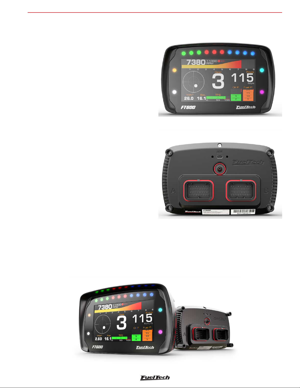
The FuelTech FT600 is a fully programmable ECU, which allows you
to change all fuel and timing tables, as the engine conditions, in real
time. You can tune your engine directly on the ECU, through its screen
touchscreen 4.3’’ or via FTManager software with high-speed USB
communication. The tuning of main fuel and timing tables may be
performed in basic (2D) or advanced (3D) mode with configurable
break points. It can be applied to any type of engine Otto cycle using
indirect injection, 2 or 4 strokes, up to 12 cylinders or 4 rotors,
gasoline, ethanol, methanol, CNG, nitromethane and other compatible
fuels.
FT600
The electronic throttle control is fully integrated to the module and
configured directly in the display without any additional computer or
module. It is possible to set alerts to dangerous situations for the
engine, such as over rev, low oil pressure, high engine temperature,
among others. These alerts can also be programmed to limit rpm or
shut off the engine bringing more security the user. The ECU also
features five maps fully independent, allowing different settings to
engines and/or cars.
The timing control can be done through distributor or crank trigger.
Thus, it is possible to work with a single coil, double coils or COP coils,
on wasted spark or sequential ignition. The fuel injectors can work on
sequential, semi-sequential or multipoint mode, with individual cylinder
trim. Tune the injection phase angle is also possible.
The equipment also has the Favorites menu, which seeks to facilitate
access to the main engine setup menus, allowing executing rapid
changes in maps. The dashboard panel is fully configurable, where
the user can change the display size and the types of readings for
each parameter, as well as reading range presented on the screen.
5
Page 6

FT600
Warranty terms
3. Warranty terms
The use of this equipment implies the total accordance with the terms
described in this manual and exempts the manufacturer from any
responsibility regarding to product misuse
Read all the information in this manual before starting the product
installation.
NOTE:
This product must be installed and tuned by specialized
auto shops and/or personnel with experience on
engine tuning.
Before starting any electric installation, disconnect the battery.
The inobservance of any of the warnings or precautions described in
this manual might cause engine damage and lead to the invalidation
of this product warranty. The improper use of the product might cause
engine damage.
This product does not have a certification for the use on aircraft or
any flying devices, as it has not been designed for such use purpose.
WARNING
- It is a good practice to save your maps on the
PC, as a security backup. In case of problems
with your ECU, this will be the guarantee that
your calibrations are saved. In some cases,
when the ECU is upgraded by the factory, its
memory may be erased also.
- It’s not possible to change the FT600’s
interface language.
Limited Warranty
This product warranty is limited to one year from the date of purchase
and covers only manufacturing defects upon presentation of purchase
invoice.
This ECU has a serial number that’s linked to the purchase invoice and
to the warranty. In case of product exchange, please contact FuelTech
tech support.
Damages caused by misuse of the unit are not covered by the warranty.
This analysis is done by FuelTech tech support team.
In some countries where an annual inspection of vehicles is enforced,
no modification in the OEM ECU is permitted. Be informed about local
laws and regulations prior to the product installation.
Important warnings for proper installation of this product:
• Always cut the unused parts of cables off NEVER roll up the
excess.
• The black wire of the harness MUST be connected directly to the
battery’s negative terminal, as well as each one of the sensors’
ground wires.
• It is recommended to connect the three black/white wires to the
engine head or block, in order to avoid electromagnetic noise
problems.
The violation of the warranty seal results in the invalidation
of the Product Warranty.
Manual version 1.7 – Jun/2018
ECU version – 3.4
FTManager version - 3.4
6
Page 7

Characteristics
FT600
4. Characteristics
Specifications
• Otto cycle engine control: 1, 2, 3, 4, 5, 6, 8, 10 and 12 cylinders;
• Wankel engines (rotary) 2, 3 and 4 rotors;
• Sequential, semi sequential and multipoint fuel control;
• Distributor and crank trigger ignition control;
• Wasted spark and sequential ignition control;
• Electronic throttle body Control (Drive-By-Wire);
• Idle speed control by electronic throttle, stepper motor, ignition
timing and PWM valve;
• Closed loop injection through oxygen sensor (wide band lambda
sensor);
• Real time programmable by the screen or PC through FTManager
Software;
Inputs
• Differential input for RPM signal;
• Differential input for cam sync signal;
• 20 input channels totally configurable - digital and analogic
(intake air temperature, coolant temperature, fuel and oil pressure,
TPS, external MAP sensor, electronic throttle and pedal position
sensors, etc);
• 2 high sensibility inputs used preferably for gear shifter force
sensor;
• Editable sensors reading scale;
• Speed sensor and integrated gyroscope;
• 103 psi internal MAP sensor (7 bar - absolute), 14.7psi of
vacuum and 88psi of positive pressure (boost);
• 1 USB port for computer and FuelTech software connection;
• 2 CAN ports for FuelTech FTCAN 2.0 or FTCAN 1.0
communication with FuelTech WB-O2 Nano, FuelTech EGT-8
CAN, Racepak IQ3, VNET, AiM, etc).
Outputs
• 32 configurable outputs channels:
• 16 open collector outputs: recommended for high impedance
injectors (up to 4 injectors per output) – it is possible to set up
to 32 injectors using external FuelTech Peak and Hold ECU;
• 8 open collector outputs with a 5V current source of:
recommended for ignition control;
• 8 PUSH-PULL or HALF BRIDGE outputs: suitable for ignition,
step motor control, electronic throttle body and to activate loads
by 12V instead of ground.
Injection control
• Sequential injection for 24 outputs;
• Closed loop fuel control through O2 sensor (wide band sensor);
• 2 injector banks (staged injection banks A and B);
• Main map to MAP or TPS to RPM;
• Main map 3D advanced until 32x32 points (completely adjustable
map index and size);
• Simplified 2D map with up to 1x32 cells per MAP or TPS and
RPM compensation of up to 1x32 cells (completely adjustable
map index and size);
• Injection time resolution 0.001ms;
• Fuel enrichment and decay adjust;
• Individual cylinder trim setting by MAP or RPM;
• Injector compensation through:
• Coolant temperature;
• Air temperature;
• Battery voltage (individual per bank);
• Throttle position (TPS);
• Starting engine map with the engine temperature;
• Fuel pump prime control;
• Prime pulse and post-start enrichment maps;
• Gear based fuel compensation;
• Gear shift fuel compensation;
• Fuel injection phase angle control;
• Deadtime compensation table by battery voltage;
Ignition control
• Sequential ignition for up to 12 cylinders;
• Main map to MAP or TPS to RPM;
• Main map 3D advanced until 32x32 points (completely adjustable
map index and size);
• Simplified 2D map with up to 1x32 cells per MAP or TPS and
RPM compensation of up to 1x32 cells (completely adjustable
map index and size);
• Ignition angle resolution 0.01°;
• Injection angle resolution of 0.01°;
• Timing compensation by air temperature;
• Timing compensation by engine temperature;
• Timing compensation by gear;
• Gear shift timing compensation;
Dashboard screen / Onboard computer
• Screen dashboard which displays different sizes and styles to
be used with any existing equipment or sensor;
• Upper tab with 10 LED lights, colored RGB and adjustable
progressive shift light;
• 4 RGB LED side lights which can be triggered by 3 different
combined settings;
• Diagnosis dashboard with real-time information of all inputs,
outputs, CAN and Status Events;
Internal datalogger
• Multiple logs recording, up to 256 channels;
• Configurable sampling rate per channel (25Hz, 50Hz, 100Hz
and 200Hz);
• Advanced mode allows individual settings for the sample rate
with 1, 5, 25, 50, 100 or 200Hz;
• Automatic activation by RPM, through the screen or by external
button;
• Data storage for up to 2h50min (24 channels at 25Hz);
• FTManager Datalogger Software for viewing and comparing logs.
7
Page 8

FT600
Characteristics
Drag race features
• Burnout mode, 2-step, 3-step;
• Timing table for rev launch;
• 2-step by wheel speed or pression/position of clutch;
• Time based RPM limiter by timing retard or ignition cut;
• Time based wheel speed or driveshaft RPM control with timing
retard or ignition cut;
• Time-based ignition timing compensation;
• Time-based fuel compensation;
• Pro-Nitrous setting for up to 6 stages, with activation control,
fuel enrichment and ignition timing maps;
• Gear shift output;
• Time based output;
• Staging control;
• Line lock brake output;
• Wheelie control;
Other features
• Integrated GearController : ignition cut for clutchless gear shifting
using a strain gage sensor on the shifter;
• Integrated BoostController: wastegate valve pressure control;
• Idle speed control by timing, step motor, PWM valve or electronic
throttle body;
• Deceleration fuel cut-off;
• Control of up to two cooling fans by coolant temperature;
• Air conditioning control;
• Fuel pump control – with 6s prime;
• VTEC control;
• Progressive nitrous control with fuel enrichment and timing retard;
• Generic duty cycle control;
• Boost activated output;
• Different options for gear detection;
Protection and Alerts
• RPM limiter by fuel or ignition cut;
• Shift light with sound and dashboard alert and/or external shift
light;
• Configurable safe mode options (RPM limit or engine shutoff):
• High or low exhaust gas temperature (EGT), O2 closed
loop limit, over boost, over rev, engine temperature, duty cycle,
oil pressure, fuel pressure and differential fuel pressure.
General characteristics
• Display brightness adjusts;
• LED lights brightness adjustment;
• Night and day mode selection by external switch and through
the menu;
• Audible and visual alert, including external shift light control;
• 5 memory positions to save different adjusts and maps;
• User and tuner protection passwords;
PC communication through USB cable and channel customization
via FTManager Software;
• Working temperature: -4 F a +158 F;
• Maximum power supply voltage: 20V;
ECU Dimensions
• 5.86 x 3.7 x 2.42 in;
Weight
• ECU: 20.74 oz;
• Box with wire harness: 117.25 oz
• Box without wire harness: 61.44 oz
Box content
• 1 FT600 ECU;
• 1 10ft wiring harness (optional to buy);
• 1 FT600 installation and operation manual;
• 1 mounting kit (4 rubber mounts, 4 washers and 4 ¼” nuts);
• 1 cover for FT600;
• 1 badge FuelTech FT600;
• 1 USB flash drive (contains FTManager Software, FT guides, etc);
• 1 Mini USB cable;
• 1 Pen;
• 1 Decals;
• 1 keychain;
8
Page 9
Characteristics
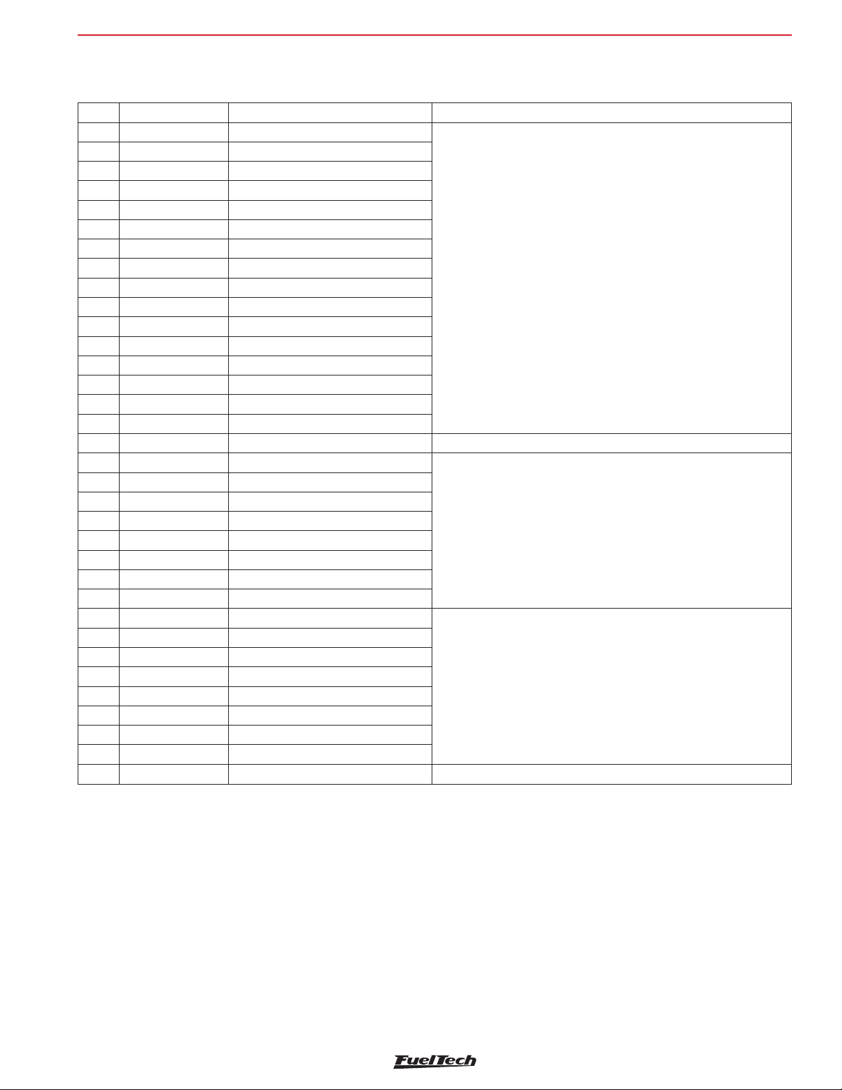
4.1 Harness connections A-connector
Pin Wire Color Function Information
1 Blue#1 Blue output #1
2 Blue#2 Blue output #2
3 Blue#3 Blue output #3
4 Blue#4 Blue output #4
5 Blue#5 Blue output #5
6 Blue#6 Blue output #6
7 Blue#7 Blue output #7
8 Blue#8 Blue output #8
9 Blue#9 Blue output #9
10 Blue#10 Blue output #10
11 Blue#11 Blue output #11
12 Blue#12 Blue output #12
13 Blue#13 Blue output #13
14 Blue#14 Blue output #14
15 Blue#15 Blue output #15
16 Blue#16 Blue output #16
17 Black/White Power ground input Ground (Engine block/head or battery)
18 Gray#1 Gray output#1
19 Gray#2 Gray output#2
20 Gray#3 Gray output#3
21 Gray#4 Gray output#4
22 Gray#5 Gray output#5
23 Gray#6 Gray output#6
24 Gray#7 Gray output#7
25 Gray#8 Gray output#8
26 Yellow#1 Yellow output#1
27 Yellow#2 Yellow output#2
28 Yellow#3 Yellow output#3
29 Yellow#4 Yellow output#4
30 Yellow#5 Yellow output#5
31 Yellow#6 Yellow output#6
32 Yellow#7 Yellow output#7
33 Yellow#8 Yellow output#8
34 Red 12V input from relay Connected to the pin 87 of the Main Relay.
These outputs are usually used for injector control. When needed, they
can be configured as auxiliary outputs.
These outputs are usually used for ignition control.
When needed, they can be set up as injector outputs or auxiliary
outputs.
By standard, Gray output #8 is used as a tachometer output.
Electronic throttle and step motor outputs. Also used as injection or
auxiliary outputs (cooling fan, fuel pump, etc.)
FT600
9
Page 10
FT600
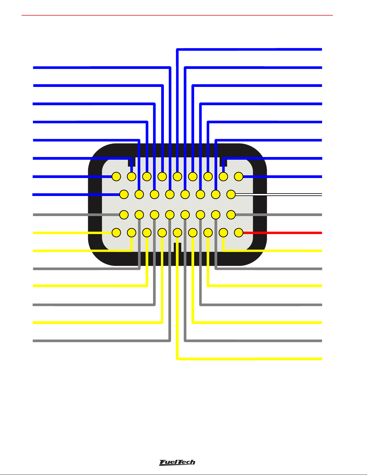
Blue output#15
Blue output#7
Blue output#16
Blue output#8
Black/white -
Blue output#9
Yellow output#1
Gray output#1
Yellow output#2
Gray output#2
Yellow output#3
Gray Output#3
Yellow output#4
Gray output#4
Gray output#5
Gray output#6
Yellow output#6
Yellow output#7
Gray output#7
Yellow output#8
Gray output#8
Red - 12V
input from relay
Chassi Grounds
Yellow output#5
Blue output#5
12
3
4
5
6789
10
11 12
13
14
15 16
17
18 19 20
21 22
23 24 25
26
27
28
29
30 31 32 33 34
A-connector diagram
Characteristics
Blue output#13
Blue output#4
Blue output#12
Blue output#3
Blue outupt#11
Blue output#2
Blue output#1
Blue output#10
Blue output#14
Blue output#6
10
Page 11
Characteristics
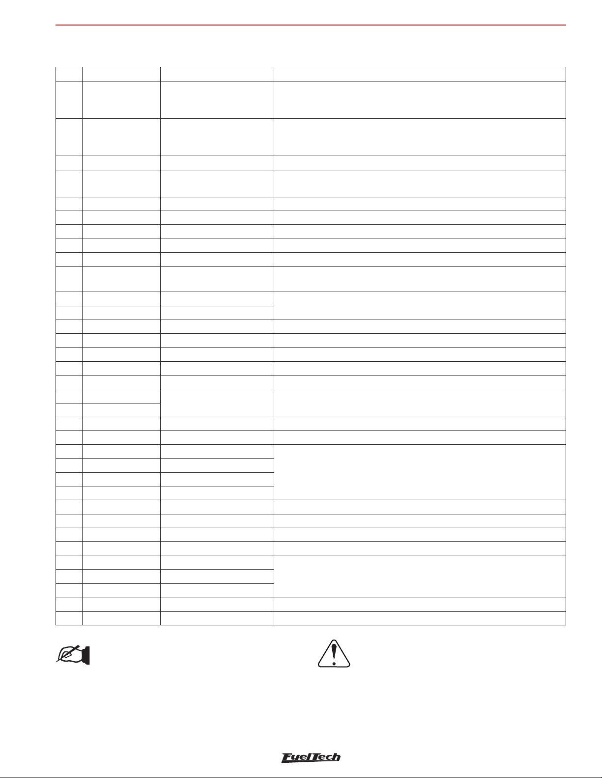
4.2 Harness connections B-connector
Pin Wire Color Function Information
Connected to the crank trigger sensor (hall or magnetic) or to the distributor.
1 Red RPM signal input
2 White
3 Red Cam sync signal input Connected to the cam sync sensor (hall or magnetic)
4 White Cam sync reference input
5 White#1 White input#1 Default: O2 sensor input
6 White#2 White input#2 Default: two-step input
7 White#3 White input#3 Default: Air conditioning button
8 White#4 White input#4 Default: Oil pressure
9 White#5 White input#5 Default: Coolant temperature
10 Black Battery negative input
11 Yellow/Blue CAN A LOW
12 White/Red CAN A HIGH
13 White#6 White input#6 Default: fuel pressure
14 White#7 White input#7 Default: Air temperature
15 White#8 White input#8 Default: pedal#2 signal input
16 White#9 White input#9 Default: pedal#1 signal input
17 White#10 White input#10 Default: MAP signal output, electronic throttle 1B input signal
18 Black/White
19 Black/White
20 White/Red CAN B HIGH CAN B HIGH
21 White#11 White input#11 Default: TPS sensor
22 White#12 White input#12
23 White#13 White input#13
24 White#14 White input#14
25 White#15 White input#15
26 Red 12V input from relay Connected to the pin 87 of the Main Relay
27 Green/Red 5V outputs for sensors 5V voltage output for TPS, electronic throttle and pedal sensors
28 Yellow/Blue CAN B LOW CAN B LOW
29 Green/Black Ground for sensors Connected the sensors ground
30 White#16 White input#16
32 White#18 White input#18
33 White#19 White input#19 Power Shift Input - Blue wire Strain gage sensor
34 White#20 White input#20 Power Shift Input - Orange wire Strain gage sensor
Magnetic RPM sensor
reference
Power ground inputs Ground (Engine block/head or Battery)
To VR sensors, use the shield wire the sensor shield. To Hall sensor, use the
shield as negative
Connected to the negative wire of the magnetic sensor. When OEM ECU is
reading the sensor in parallel, split this wire with OEM sensor negative - Do not
connect when using hall effect sensor.
Connected to the cam sync sensor (hall or magnetic)
- Use the shield as negative to the sensor
Connected directly to the battery negative with no seams. Do not connect this
wire to the chassis, engine block or head.
CAN A
Sensors input
Sensors input31 White#17 White input#17
FT600
NOTE:
When using the GearController function connect the
White wire from the shifter to ground for sensors
Green/Black (pin #29).
IMPORTANT:
Fuel only: When using this option, the RPM signal
input cannot be connected to a coil high voltage
signal because the input has no protection and
will damage the trigger input on the ecu. Please
use a tach output, another rpm source or an
ignition coil to tach adapter module to avoid
damage to the unit.
11
Page 12
FT600
GND
White magnetic RPM-
Yellow/Blue - CAN_A_LOW
Red- sync signal inputCAM
White/Red - CAN_A_HIGH
White sync- sensor referenceCAM
White input#6
White input#1
White input#2
White input#8
White input#3
White input#9
White input#4
White input#10
White input#5
Red - 12V input from relay
Black/white
Green/Red -
Black/White -groundchassis
Yellow/Blue CAN_B_LOW
Red/white CAN_B_HIGH
Green/Black - Ground for sensors
White input#11
White input#16
White input#12
White input#13
White input#17
White input#18
White input#14
White input#19
White input#15
White input#20
Black Shielded Cable
Gray Shielded Cable
White input#7
Red RPM signal input
sensor reference
chassis ground
5V output sensorsfor
12
3
4
5
6789
10
11 12
13
14
15 16
17
18 19 20
21 22
23 24 25
26
27
28
29
30 31 32 33 34
DO NOT USE FOR HALL
SENSOR GROUND
DO NOT USE FOR HALL
SENSOR GROUND
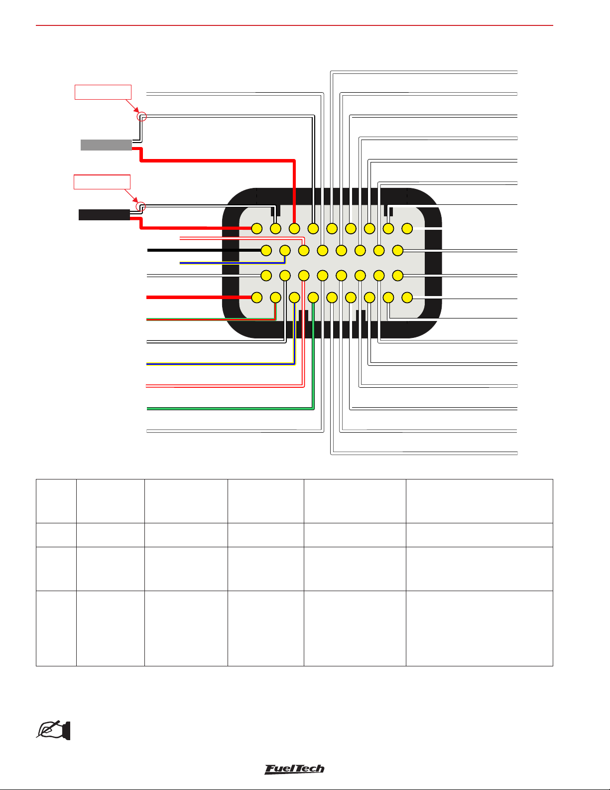
B-connector diagram
Characteristics
4.3 Output table of FT600
Wire
color
Blue
Gray
Yellow
Output type
Open collector
(Lo side)
Open collector
with current
source in 5V
(Lo side)
PUSH-PULL or
HALF BRIDGE
* Total max current combined with all outputs triggering loads by negative: 30A continuous
** Total max current combined with all outputs triggering loads by positive: 20A continuous
Max current
for negative
activation (0V) for
each output
5A*
1A* 30mA in 5V
5A* 5A** in 12V
Max current
for positive
activation for
each output
Can’t activate by
positive
Fuel injectors, relays,
solenoid valves
Inductive ignition control,
fuel injectors, relays,
solenoid valves
Electronic throttle, step
motor, MSD/M&W and
other ignitions activated
Application Notes
Triggers loads always by negative
Triggers loads always by negative
When used to control relays, valves or
any other load by negative, there is
a risk of 12V return to the ECU. This
will keep the ECU always powered on.
In this case, an external diode or a
by 12V
relay with built-in diode is required
for protection.
12
NOTE:
Blue outputs cannot control ignition because they do not have a pullup resistor.
Page 13
Characteristics
FT600
4.4 PowerShift Connector
The FT600 wiring harness comes with the gear strain gauge sensor
connector. In case the vehicle isn’t equipped with a gear strain gauge,
this connector can be removed and it’s white inputs can be used for
other functions.
4.5 Auxiliary outputs
FT600’s outputs can be set up in many different ways, they have
different capacities according to the function. Bellow is some
important information about them:
Blue outputs [#1 to #16]: by default, used as injector outputs. Each
one of them can control up to:
- 6 saturated injectors impedance above 10 Ohms (maximum of
24 injectors considering all of the blue outputs)
- 4 saturated injectors impedance between 7 and 10 Ohms
(maximum of 16 injectors considering all of the blue outputs)
The use of a Peak and Hold driver is mandatory when the number
of injectors is higher than the maximum quoted above or when using
low impedance injectors (impedance below 7 Ohms).
During the Engine Setup configuration, blue outputs will be selected
automatically from Blue #1 to Blue #16.
When more than 16 injector outputs are needed, the ECU will use
Gray #1 to Gray #8 or Yellow #1 to Yellow #4. In this case, the use
of a Peak and Hold driver is mandatory on Gray and Yellow outputs
(for saturated and low impedance injectors).
Blue outputs not used to control fuel injectors may be used as auxiliary
outputs (controlling fuel pump, cooling fan, etc.). In this case, the use
of a relay is mandatory.
Gray outputs [#1 to #8]: by default, used as ignition outputs.
According to the engine setup, they can be set up as injectors or
auxiliary outputs.
During the Engine Setup configuration, ignition outputs will be selected
automatically from Gray #1 to Gray #8. It’s not possible to have more
than 8 ignition outputs.
Gray outputs not used for ignition control can be set up as injectors
outputs (the use of a Peak and Hold driver is mandatory) or as auxiliary
outputs (the use of a relay is mandatory).
Yellow outputs [#1 to #8]: by default, they’re used as electronic
throttle control (Yellow #1 and #2) or stepper motor control (Yellow
#1 to #4).
The yellow outputs that will not be used for electronic throttle control
can be used as auxiliary outputs or for injectors. When using injectors
for the integrated BoostController, the output can be connected directly
to the injector, but when using injectors for fuel, the use of a Peak and
Hold driver is mandatory for both high and low impedance injectors.
This is because this output may present minimal differences in the
injection time when controlling fuel injectors without Peak and Hold.
Tach output: by default, it is setup on in the gray #8, but if this pin
is needed for other functions, we recommend to using one of the
yellow outputs for tach. If the yellow wires are being used, you can
use any other output with a 1k ohms pull-up resistor connected from
the signal to 12V.
4.6 Internal MAP sensor
This ECU is equipped with an internal MAP sensor. Use a 6mm
pneumatic hose (4mm internal diameter) to connect the sensor to
the intake manifold. Pneumatic hoses are flexible, durable and highly
resistant. Usually found in black or blue colors.
Silicon hoses are not recommended because they can be easily bent,
blocking vacuum/boost readings on the ECU MAP sensor.
Use a hose exclusively for FT MAP sensor, avoiding splitting it with
valves, gauges, etc. Connect it to any spot between the throttle and the
engine head. Its length must be as short as possible to avoid lags and
errors on the sensor readings. When using individual throttle bodies,
it is a good idea to connect all intake runners into a single point and
then connect to the FT MAP sensor; otherwise, MAP readings may
be erratic or inaccurate.
4.7 USB port
The USB cable is used to update the ECU firmware version, setup
maps and adjusts trough a computer and FTManager software and
download data recorded by the internal datalogger.
4.8 FuelTech CAN network
FuelTech CAN port is a 4 way connector placed on the wiring harness
of the ECU and is responsible for FT600 communication with other FT
modules (as KnockMeter and GearController) and Racepak dashboards.
A FuelTech CAN-CAN cable is used to establish a connection between
them.
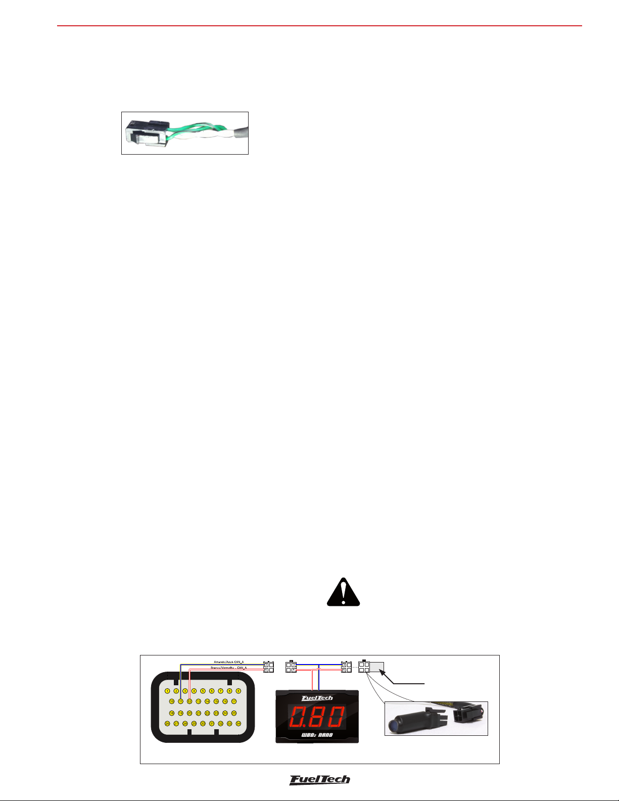
ATTENTION:
For the correct operation of the CAN Network, its
mandatory to use the CAN resistor as shown in the
following image.
Connector B - FT600
Terminador
Anywhere equipment CAN FuelTech (WB-O2 NANO,
Alcohol O2, EGT8, WB-O2 SLIM)
13
Page 14
FT600
First steps with FT600
5. First steps with FT600 read before installation
This chapter is a step-by-step guide that must be followed to start
FT600 basic setup before electric installation, as the function of
each wire may vary according to engine setup (number of cylinders,
injectors control mode, ignition coils and auxiliary outputs).
1. Connect the flash drive in the PC USB port and install the
FTManager software. Remember to check if the software and
the ECU are in the latest version at www.fueltech.net.
2. Connect FT600 to the computer using the USB cable included
on the package. The ECU will be powered up;
3. With the ECU in hands go through chapter 6, that introduces all
basic information about menu navigation and operation;
4. Chapter 7 guides the user through all the menus where data
regarding the engine must be setup (crank trigger signal, injectors
and ignition control modes, etc.);
5. The last step before the electric installation is to check harness
connections. Go to the “Engine Setting” menu then click the last
option “Wiring harness diagram”. Check and write down the
connections and use it as guide to know how functions were
allocated to the pins.
6. Chapters 8 to 14 guide through details related to the electrical
installation of injectors, coils, 12V inputs, grounds, sensors,
etc. Chapter 25 shows full wiring diagrams as example for your
installation;
7. Chapter 15 gathers information on sensors settings for
temperature, pressure, RPM, speed, etc.
8. With the electric installation finished, proceed to chapter 15.14
and check all the information needed for the first start of the
engine, ignition calibration, sensors checking, etc.
9. Lastly, chapters 17 to 24 show detailed descriptions about all
functions of the ECU. It is very important and informative to read
these sections, as they also outline every function and operation
that the FT can perform.
6. Getting to know the ECU
6.1 Dashboard
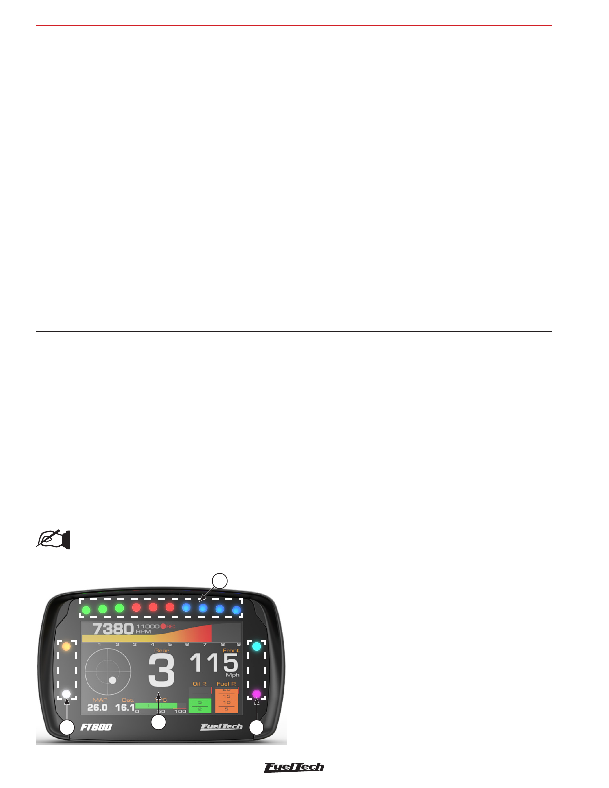
FT600 has a whole new dashboard, completely redesigned and
customizable to improve visualization in any kind of vehicle.
1- Top LED bar (shift lights): configurable shift light by gear;
2- Side LEDs (alerts): many different options of activation and alerts;
3- Dashboard: fully customizable and redesigned with new gauges
(3x2 size), besides a G meter;
NOTE:
For more info check chapter 23.11.
1
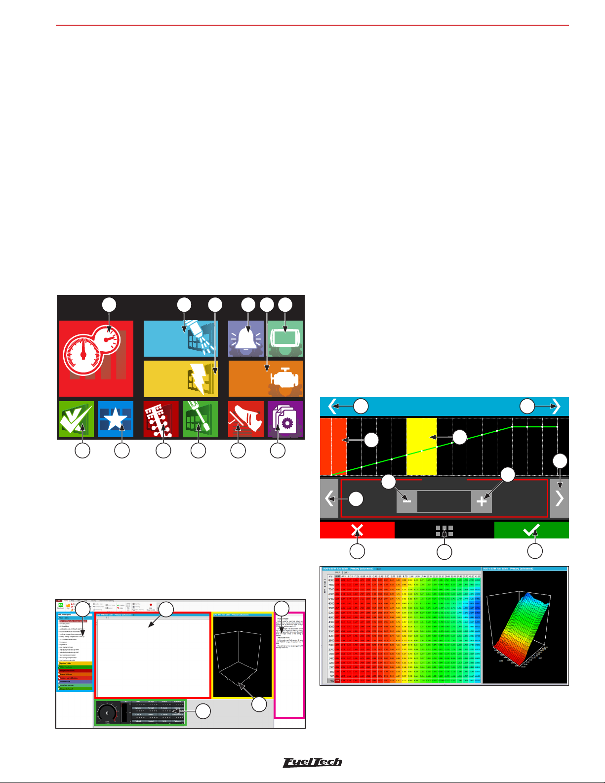
6.2 Main menu
Navigation through touchscreen is intuitive, because the ECU display
makes the access to information very easy, eliminating physical
buttons. So, all changes on maps, setups and functions are done by
light touches on the screen.
To enter menus, press the screen twice, just like a double click. This is
a feature that prevents the user from entering the wrong menu when
managing the ECU inside the car.
1 - Dashboard: Shows real time engine information (RPM,
Temperature, pressure, timing, injection time, etc.)
2 - Fuel Tables Adjust: Main fuel map, overall fuel trim, RPM
compensation, TPS idle fuel table accel fuel enrich and
decay, engine and intake temp, compensation battery voltage,
compensation, post start enrich, etc.
3 - Ignition Tables Adjust: Main ignition map, overall ignition
trim, MAP / TPS compensation, air and engine temperature
compensations , individual cylinder trim, timing split, etc.
4 - Alert Settings: Access to shift alert settings, safe mode RPM
limiter, alerts by fuel and oil pressure, TPS, etc.
14
5 - Engine Settings: Engine basics info as ignition mode, RPM
signal, pedal/throttle settings, idle actuator, injectors deadtime,
ignition dwell, wiring harness diagram.
3
22
6 - Interface Settings: LCD backlight and alert sounds, dashboard
configs, measurement units, touchscreen calibration serial number
and version.
Page 15
Main Menu
Fuel
Tables Adjust
Ignition
Tables Adjust
Engine
Settings
Dashboard
Getting to know the ECU
FT600
7 - File Manager: Used to generate FuelTech Base Map, copy, delete
and manager map files.
8 - Sensors and Calibration: Setup and calibrate FT600 sensors,
electronic throttle, O2 sensor, etc.
9 - Other Functions: Internal datalogger, RPM limiter decel, fuel
cut-off, thermatic fans, progressive nitrous, boost control idle
speed, etc.
10 - Drag Race Features: Burnout mode 3-step, 2-step, spool assist
table, Gear shift output, time based enrichment and timing ProNitous.
11 - Favorites: Shortcuts to the most used menus and functions.
12 - Diagnostic Panel: Check inputs and outputs status and all
information of what the ECU is reading and doing is real time.
1 2 3 4 5 6
When entering a map or setting up a function, there are some buttons
on the screen that act as described below:
18 - Red area shows the point selected for editing;
19 - Yellow area is shown only when the engine is running and shows
the actual condition of MAP, temperature, TPS, etc.;
20 - Button +: increases the value of the selected parameter;
21 - Button >: Selects next parameter on the map;
22 - Save/Select Button: Saves any changes done to the map or
configuration and returns to the main menu;
23 - Home Button: Returns to the home screen. If any maps or
configurations were changed, it aks for confirmation;
24 - Cancel/Back Button: Cancels all changes done to the maps or
configuration and returns to previous menu;
25 - Button -: Reduces the value of the selected parameter;
789101112
You can navigate through all menus with FTManager (available in the
flash drive) and mini USB cable. The software initial screen is shown
below:
13 - Quick access;
14 - Function table;
15 - Help;
16 - Function or map graph
17 - Real time dashboard;
13
14
15
26 - Button <: Selects previous parameter on the map;
27 - Button <>: Change the screen (if available on the menu);
27 27
18
26
24
TPS compensation
25
10 %
+15
23
19
20
%
22
21
17
16
In the FTManager all commands are accessible through mouse and
keyboard. The advance (3D) fuel table is shown below:
15
Page 16
FT600
Main Fuel Injection Table
3500
RPM
4000
1,00
ms
+
-
B
A
3,220 4,052
3,943
0,80
bar
3,140 (20%)
15,980 (106%)
3,080 3,8602,300
2,338
2,388
3000
0,60
Painel de
Instrumentos
Getting to know the ECU
Advanced edition mode
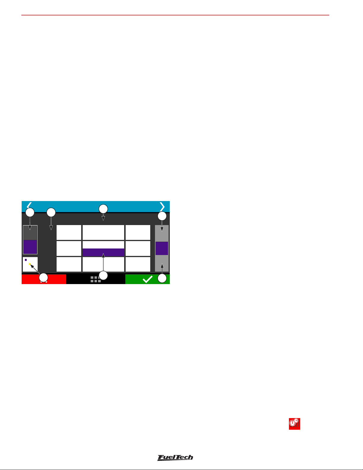
In the advanced mode, both fuel and timing tables will be in a 3D
table format. Some functions will also be presented in a 3D table
only. The navigation is very simple, in the left bottom corner you can
see the current position in the table. Green marker is for bank A and
purple for bank B. A yellow marker will show the current engine table
position. If you click this icon, you will taken to the current load/tps
and rpm position.
To scroll through the vacuum/pressure or TPS, click in the horizontal
direction of the table, to RPM ranges, click in the vertical direction.
1 - Injector Bank;
2 - Engine RPM;
3 - MAP / TPS;
4 - Use button + and - to increase or decrease injection time;
5 - Injection time and percentage. The above value corresponds to
bank A value below to bank B;
6 - Table position mini map:
Yellow: click this icon to go directly to the point of the map
where the engine is working at the moment;
Purple: That’s the position of the table that’s being shown by
the screen;
• (Ctrl) + (C) – copy;
• (Ctrl) + (V) – paste;
• (Ctrl) + (+) – fast value increment. Increases 0,100ms in the
fuel table. On VE and DC the change is related to milliseconds;
• (Ctrl) + (-) – slow value decrement. Decreases 0,100ms in the
fuel table. On VE and DC the change is related to milliseconds
• (+) – increment in 0,010ms steps. On VE and DC the change is
related to milliseconds
(-) – decrement in 0,010ms steps. On VE and DC the change is
related to milliseconds
• (Shift) + (+) – slow value increment in 0,001ms steps. On VE
and DC the change is related to milliseconds
• (Shift) + (-) – slow value decrement in 0,001ms steps. On VE
and DC the change is related to milliseconds
• (A) – sum;
1 2
6
3
4
5
4
6.3 FTManager shortcuts
• F1 – Show and hide help panel;
• F2 - Show and hide quick access panel;
• F3 – Show and hide graph;
• F4 – Show and hide real time (FTManager real time dashboard);
• F5 – display main table and hide every other function;
• (M) – multiply;
• (Space bar) – pops up a box to fill a value;
• (I) – interpolate the selected cells;
• (V) – interpolate vertically the selected cells;
• (H) – interpolate horizontally the selected values;
• (S) – site function. Moves the cursor to actual engine position;
• (Home) – moves the cursor to the leftmost cell;
• (End) – moves the cursor to the rightmost cell;
• (Page Up) – moves the cursor to the topmost cell;
• (Page Down) – moves the cursor to the bottommost;
6.4 Dashboard screen
• F6 – change the main fuel table measurement unit: milliseconds
• F7, F8, F9, F12 – no shortcut;
• F10 – datalog overlay - vertical split screen
• F11 – datalog overlay - horizontal split screen
16
(ms), volumetric efficiency (%VE), duty cycle (%DC), fuel flow
(lb/hr or customized unit)
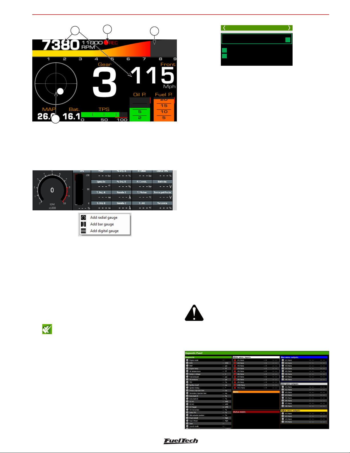
When the engine is running, the dashboard screen shows real-time
information of sensors that are being read by the ECU.
Chapter 23.3 has more information on how to change the instruments
on this screen.
To access the dashboard screen, touch the icon , located at
the main menu.
Page 17
Getting to know the ECU
FT600
1
2
4
1 - Real time readings;
2 - Internal datalogger status;
3 - Touch this whole area to access the main menu;
4 - Accelerometer graphic;
The dashboard is also shown in real time in FTManager:
3
Crank RPM
7325
Fuel injection
Timing
Diagnostic 1/11
Crank
SYNC
Cam RPM
7325
Cam sync angle (°)
90,4
Pages 2 to 9 shows input/output at the left column, position/command
sent to the actuator, (outputs)/voltage read (inputs) at the central
column and the main information used to calculate the position/
command at the right column. For a thermatic fan output, i.e., diagnostic
panel shows its status at the center column and the engine coolant
temperature at the right column.
On page 10 are information regarding the engine RPM signal readings.
Below are some common errors and possible causes:
Crank trigger error: gap detected at the wrong spot - it detected
the gap (missing teeth) in the wrong place; it can also happen with a
trigger wheel without missing tooth when there is a cam sync signal
in the wrong place. Also occurs in engines with a very light flywheel
that accelerates and decelerates quickly during compression strokes
at engine startup and running.
Crank trigger error: wrong number of teeth - number of teeth is
different on the crank trigger wheel than what is set at ECU. Electrical
noise can cause a reading of a “ghost” tooth, for example.
To add or remove gauges, click with mouse right button in a free
space and select the gauge type you want to (radial, bar or digital).
6.5 Diagnostic panel
The diagnostic panel is a function which shows all ECU inputs and
outputs parameters and is very helpful to detect anomalies in FT600
tune, sensors and actuators. To access it through FTManager, click on
Diagnostic Panel tab at quick access panel.
The Diagnostic Panel is a tool used to detect anomalies on FT600
inputs, outputs, sensors and actuators. In order to access it, touch its
icon , at the main menu.
Information is split on 11 pages:
• Page 1: Diagnostic Crank RPM sensor and Cam RPM sensor;
• Page 2: general engine information;
• Page 3: status of white inputs;
• Page 5: status CAN Communication;
• Page 6: status of blue outputs;
• Page 8: status of gray outputs;
• Page 9: status of yellow outputs;
• Page 10: RPM reading diagnostics;
• Page 11: Test time based feature;
Crank trigger error: missed tooth reading - the ECU detected less
teeth then it should have. Also happens in engines with a very light
flywheel that accelerate and decelerate very fast during compression
strokes at engine startup and running.
Crank trigger error: abnormal acceleration - tooth error detection.
Usually caused by signal noise.
Cam sync sensor: signal noise - cam sync signal detected in the
wrong spot. Typically this error is caused when the ECU detects noise
in the cam sync sensor signal or when the cam trigger wheel has
more than one tooth.
ATTENTION
When the 2-step and 3-step are set to activate
by speed, its operation can be checked through
the page 1 of the Diagnostic Panel, not through
page 2, since you are not using an analog input
(white wire) to switch.
17
Page 18
FT600
Diagnostic 2/6
4,994 V
4,995 V
0,094 V
4,995 V
4,509 V
4,998 V
0,663 V
0,000 V
0,000 V
0,021 V
0,000 V
1: O2 sensor #1
2: Two-Step
3: Air conditioning
4: Oilpressure
5: Engine temperature
6: Fuel pressure
7: Air temperature
8: Avaliable
9: Avaliable
10: MAP
11: TPS
bar
°C
bar
°C
bar
%
White wires: Inputs
1,10
Disab.
Disab.
9,98
1
9,98
10
0
0
0,84
0,00
Getting to know the ECU
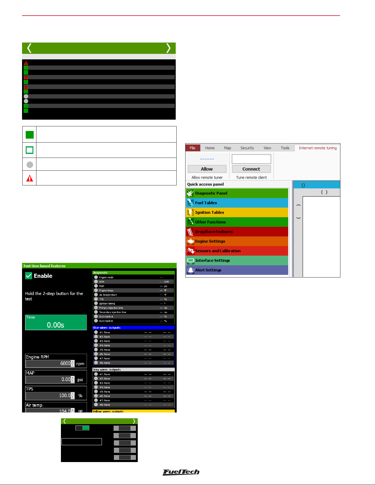
Diagnostic panel labels
Input or output is configured, enabled and working properly.
Input or output is configured and disabled.
Input or output has not been set up.
Input or output is set up, but there is an abnormal behavior.
6.6 Test time based features
6.7 Internet Remote Tuning
Since update 3.3, FTManager has a new feature wich will make it easier
to connect 2 computers that have FTManager installed.
To Start a connection go to the “Internet Remote Tuning” tab on
FTManager.
- Allow remote tuner: This option allows for another remote computer
to connect to your FTManager. Click on “Allow” to generate a 6 digit
password wich must be informed to the tuner that’s going to connect
to your computer.
- Tune remote client: This option allows you to connect to another
remote computer using the 6 digit password generated on the clients
FTManager.
This menu allows you to run the output test controlled by time. To
start this test the engine must be turned off and the ignition switch
on (12V). The test starts when the 2-step button is pressed and lasts
as long as the button is pressed.
While the test is performed the RPM values, MAP, TPS and temperatures
can be changed in real time.
18
Test time based features
Desat. Ativ.
Hold the 2-step button for the
test
Tempo (s): 0,00
RPM
MAP
TPS
T.air
T.engine
1000
-
0,00
-
90,0
-
70,0
-
70,0
-
+
+
+
+
+
Page 19
Engine settings
FT600
7. Engine settings
FuelTech ECUs leave the factory without maps or adjustments, so you
need to create the injection maps, ignition and the inputs and outputs
settings before running the engine.
The FuelTech Default is an automatic calculation of the basic injection
and ignition maps for your engine based on the information provided
in the “Engine Settings”. Performing this automatic adjustment every
injection and ignition maps, including temperature compensation, etc.
Will be filled based on your engine characteristics.
The information provided must be correct and consistent, maximum
RPM and boost values should be according to the engine capacity and
the injectors should be properly sized to the estimated engine power.
The use of an instrument, such as oxygen sensor (wideband
recommended) and/or an analyzer of exhaust gases, to make the
analysis of the air/fuel mixture is extremely important.
Caution, especially during start-up, is needed, since it is an initial tune
that will start most engines, there are no guarantees for any situation.
Be extremely cautious when tuning your engine. Engine should not be
operated at maximum load until the air fuel ratio has been confirmed.
To generate a new map through the touchscreen, just get in a setting
that is empty and a message appears telling you that the setting is
empty and asking if you want to create a new tune.
File Manager 2/2
Adjust 1 [Blank]
Copiar ajuste para:
Blank file map!
Do you want to run the
Ajuste 1 xxxxxxxxxxxxxxxx
configuratio wizard?
Ajuste 2
Do not show this message again
Ajuste 3
Ajuste 5 [Vazio]
Yes
No
In the first screens of the wizard are the settings for measurement
units used by the ECU. Select the temperature, O2 sensor, pressure
and speed units.
The following screens are part of the engine configuration menus and
are described in the following chapters. Follow the wizard by reading
the next pages.
Measurement Units 1/2
Pressure unit
bar
Psi
kPa
Temperature unit
°C
°F
Measurement Units 2/2
O2 Sensor unit
Lambda
AFR
Speed unit
kph
mph
Start tuning with a rich map and a conservative timing, because starting
with a lean map and advanced timing can severely damage the engine.
To create a default map by FTManager, click the “File” menu and
then “New” to start the wizard. The menu “Engine Settings” will be
passed in sequence.
Check in later chapters the descriptions of all these options required
to complete the step by step and create the default map.
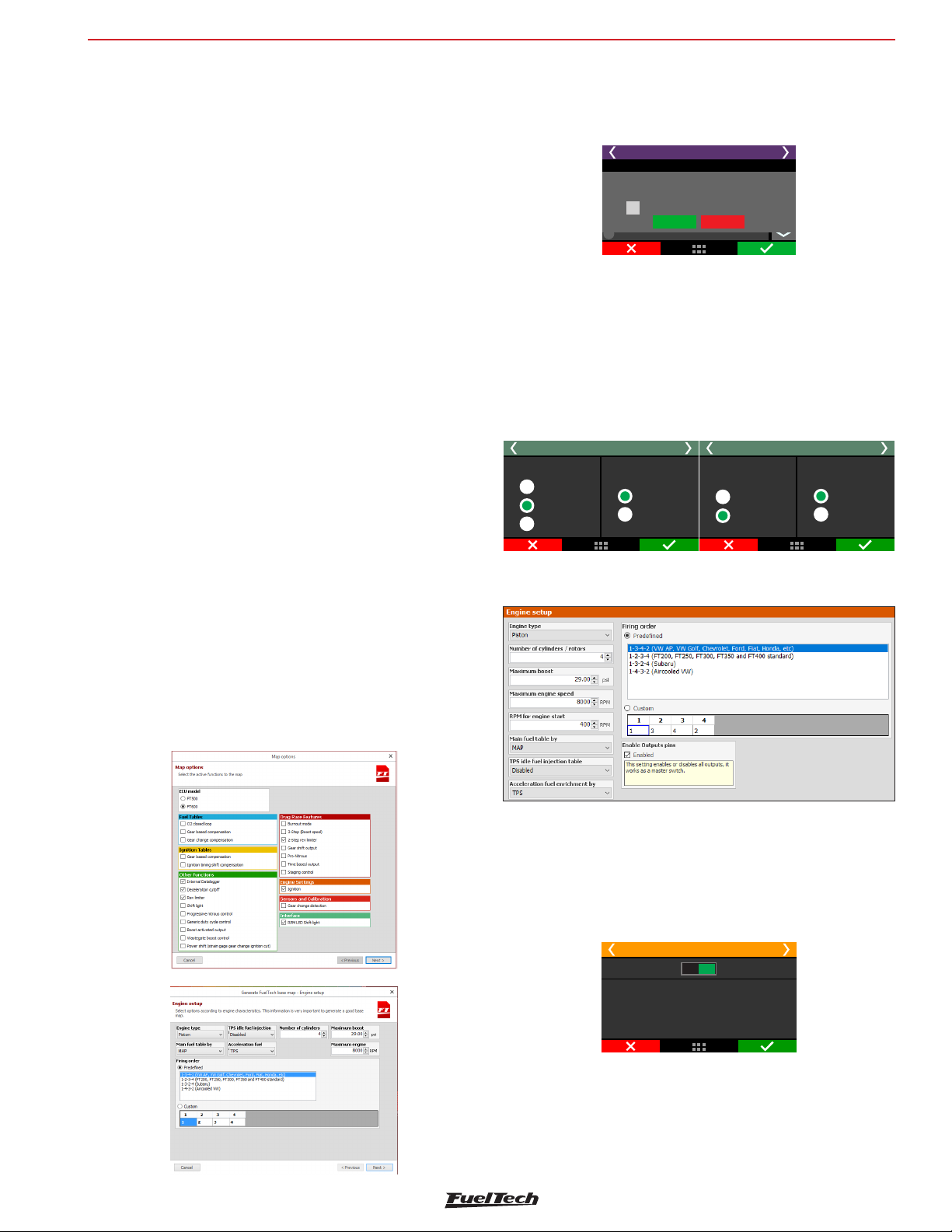
7.1 Engine setup
Enable outputs
Basically prevents the outputs from turning on (injection, ignition and
auxiliary outputs).
Engine setup 1/7
Disabled Enabled
Enable outputs
This options enables allFT500 outputs.
It must be the last thing to be setup before
cranking the engine. Until this is
done, no output will be activated.
19
Page 20
FT600
Engine settings
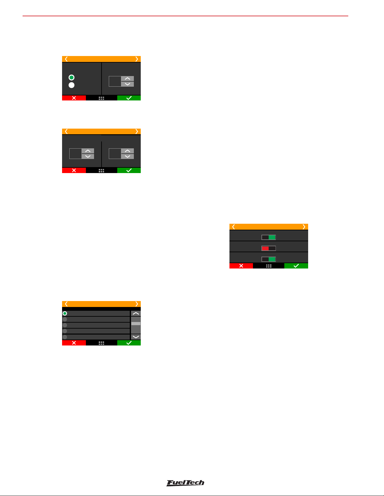
Engine type and number of cylinders
Select the type of engine, piston or rotary and the number of cylinders
or rotors.
Engine setup 1/6
Engine type:
Piston Engine
Rotary Engine
Number of
cylinders:
4
Cylinders
Engine limits
Setup the maximum RPM and maximum boost.
Engine setup 2/6
RPM
Engine limits
Maximum Boost
3,50
bar
Maximum Engine Speed
9500
Maximum engine speed: setup the engine maximum RPM. All fuel
and timing maps will be created with its last point on this RPM. This
parameter is also used to calculate fuel injector’s percentage of use.
8 cylinder engines:
• 1-8-4-3-6-5-7-2: Chevrolet V8 (majority);
• 1-8-7-2-6-2-4-3: Chevrolet LS
• 1-5-4-2-6-3-7-8: Ford 272, 292, 302, 355, 390, 429, 460;
• 1-3-7-2-6-5-4-8: Ford 351, 400 and Porsche 928;
• 1-5-4-8-6-3-7-2: Mercedes-Benz;
10 cylinder engines
• 1-10-9-4-3-6-5-8-7-2: Dodge V10;
• 1-6-5-10-2-7-3-8-4-9: BMW S85, Ford V10, Audi, Lamborghini
V10;
12 cylinder engines
• 1-12-5-8-3-10-6-7-2-11-4-9: Jaguar V12, Audi, VW, Bentley
Spyker W12;
• 1-7-5-11-3-9-6-12-2-8-4-10: 2001 Ferrari 456M GT V12;
• 1-7-4-10-2-8-6-12-3-9-5-11: 1997 Lamborghini Diablo VT;
Customized
• In case the firing order of your engine is not listed on the ECU,
there’s a mode that allows full customization of the firing order.
Maximum boost: maximum boost for fuel and ignition maps. For
naturally aspirated engines, set this option as 0.0 psi. For turbocharged
engines, use 10psi above the maximum boost the engine will effectively
be using. In case of an overboost, the ECU will apply the last injection
timing set on the map. This option doesn’t control boost pressure, is
just a limit for fuel and ignition maps.
Firing Order
Select the firing order according to your engine.
Firing order: 200, 250, 300, 350 and 400 defaultFT FT FT FT FT
1-3-4-2
1-2-3-4
1-3-2-4
1-4-3-2
Custom
4 cylinder engines
• 1-3-4-2: majority of engines, VW AP, VW Golf, Chevrolet, Ford,
Fiat, Honda, etc.;
• 1-3-2-4: Subaru;
• 1-4-3-2: air-cooled VW;
• 1-2-4-3: Motorcycles (majority)
Engine setup 3/6
Main fuel table
Engine setup 5/6
Main fuel table
TPS MAP
TPSidle fuel injection table
Disab. Enab.
Acceleration fuel enrichment
TPS MAP
MAP: this mode is indicated for turbo or naturally aspirated engines.
That’s the mode that better represents engine load, because engine
vacuum varies under different loads, even with the throttle on the
same position.
TPS: this option is mostly used on naturally aspirated engines with
aggressive camshafts, when this causes the vacuum on idle and under
low load conditions to be unstable. When this option is selected, MAP
compensation is available for fuel and timing maps.
TPS idle fuel injection table: This is the mode the fuel injection
on idle speed will be controlled. When enabled, a table that relates
injection time versus engine RPM is activated whenever TPS is equal
to 0%. Enable this feature an engines with high profile camshafts and
unstable vacuum on idle.
5 cylinder engines
•
1-2-4-5-3: Audi 5 cylinders, Fiat Marea 20V and VW Jetta 2.5;
6 cylinder engines:
• 1-5-3-6-2-4: GM in line (Opala and Omega), VW VR6 and BMW
in line;
• 1-6-5-4-3-2: GM V6 (S10/Blazer 4.3);
• 1-4-2-5-3-6: Ford Ranger V6;
20
For street cars with stable vacuum on idle, it is recommended to keep
this feature disabled. In this case, injection time for idle will be set up
directly on the vacuum ranges on the main fuel MAP.
Accel fuel enrichment: use this parameter set up as TPS whenever
possible, as this sensor reacts faster than the MAP sensor to indicate
a quick change of position in the throttle.
Page 21
Engine settings
FT600
Engine setup 6/6
RPMfor
When the engine isRPM
lower than this value,
the assumes the start-upECU
routines. Above this ,RPM
values of injection, ignition
and actuators position are the
ones set up on the maps.
engine start
400
RPM
RPM for engine start: set up a RPM limit above which the start-up
routines are disabled. Below this RPM, all the injection, ignition and
actuator positions set up for engine start are used.
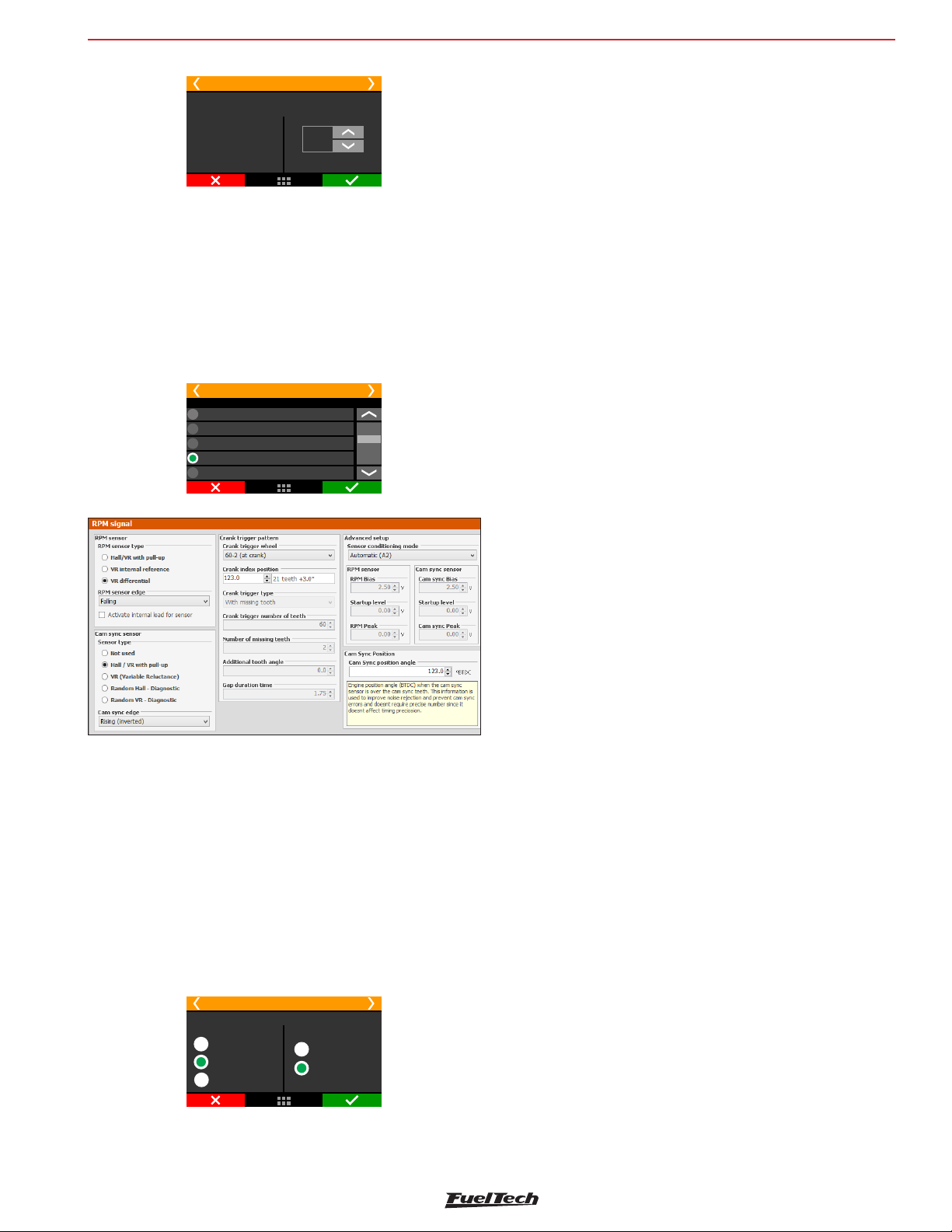
7.2 RPM signal
RPM signal is the most important information to run the engine properly.
This menu is where the RPM input will be set up.
Option selection:
36-1 (crank)
36-2 (crank)
48-2 (crank)
60-2 (crank)
Custom
RPMsignal 1/4
VR internal ref: Only use this option when told by our tech support.
This is used for compatibility with older units only.
VR Differential: Select this for VR sensors; it’s less susceptible to
electromagnetic interference. When the crank trigger signal is split
with the OEM ECU this option is mandatory.
Hall/VR with pull-up: Select when using Hall effect RPM sensor or
when experiencing problems with electromagnetic interference.
RPM Signal Edge: this option changes the way the ECU reads the
RPM signal. As there’s no simple way of telling which one is the correct
option (without an oscilloscope), select the option Standard (Falling
Edge). If the ECU sees no RPM signal during initial startup, change
this parameter to Inverted (Rising Edge)
First tooth alignment: set here the crank trigger alignment related to
the TDC. This alignment can be checked by turning the engine to the
cylinder #1 TDC and counting, counterclockwise, angle distance, from
the crank trigger gap to the RPM sensor. If there crank trigger has no
gap, the angle distance is from the previous teeth to the RPM sensor.
For engines with distributor and Crank trigger, check our Technical
Support for information about the alignment in use.
Engines with crank trigger: select the crank trigger pattern.
Select the crank trigger or distributor pattern. In case of a crank trigger
without missing tooth and multi-coils, a cam sync sensor is required.
When using a single coil, the cam sync sensor is not mandatory. A
several options of standard patterns are available for using with multicoils or distributor based systems.
RPM Sensor
Select the RPM sensor used on the vehicle, VR or Hall Effect.
RPMsignal 2/4
Type
VR internal ref.
VR Differential
Hall/ with pull-upVR
Crank Ref. Sensor
Edge
Rising Edge
Falling Edge
Below is a table with known alignment values and configurations for
most of the cases:
21
Page 22
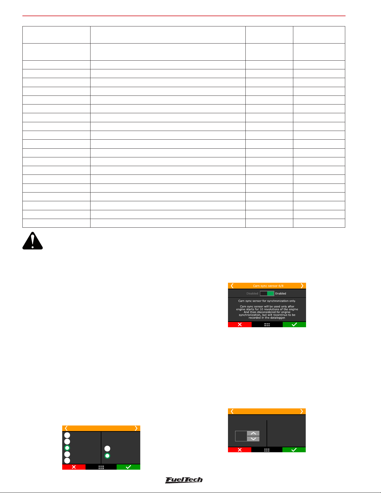
FT600
Engine settings
Crank trigger - pattern Engine/brand
60-2 BMW, Fiat, Ford (inj. Marelli), Renault, VW, GM
Recommended
index position
123º (GM)
90º (others)
Cam sync sensor
Not mandatory
48-2 Not mandatory
36-1 Ford (ECU FIC) 90º Not mandatory
36-2-2-2 Subaru 55º Not mandatory
36-2 Toyota 102º Not mandatory
30-1 Not mandatory
30-2 Not mandatory
24-1 Hayabusa 110º Not mandatory
24-2 Suzuki Srad 1000 Not mandatory
24 (crank) or 48 (cam) 60º Falling edge
15-2 bikes Honda CB300R Not mandatory
12+1 Honda Civic Si 210º or 330º Not mandatory
12-1 bikes Honda/Suzuki/Yamaha Not mandatory
12-2 Not mandatory
12 (crank) or 24 (cam) Motorcycles/AEM EPM/ Honda distributors 92/95-96/00 Falling edge
8 (crank) or 16 (cam) Falling edge
4+1 (crank) Not mandatory
4 (crank) or 8 (cam) 8 cylinders 70° Falling edge
3 (crank) or 6 (cam) 6 cylinders 60º Falling edge
2 (crank) or 4 (cam) 4 cylinders 90º Falling edge
WARNING:
Ignition calibration values on this table are just a
start point. ALWAYS perform the ignition calibration
according to chapter 16. When the ignition is not
correctly calibrated, the timing shown on the ECU
screen is different from the one that is being applied
Cam sync sensor for synchronization
Cam sync signal will be used only for 10 revolutions after engine start
and after that will be disconsidered for engine synchronization but it
will still be recorded on the datalogger.
to the engine. This may cause serious damage to the
engine.
Cam sync sensor
This option indicates if a cam sync sensor will be used and if it uses a
hall effect or magnetic variable reluctance (VR) sensor. This sensor is
mandatory when controlling fuel or timing in sequential mode. Without
cam sync sensor the injection mode will be only semi-sequential or
multipoint. Ignition will be always wasted spark.
Random cam sync sensor option is a test mode that automatically
assumes a position for the cam sync signal. Use this only for testing
purposes, as this may cause misfires in some applications. Use this
option only for tests, because with individual coils and sequential
ignition the firing order can be lagged (inverted) in 360º, so the
engine won’t start.
Cam sync sensor edge: this option changes the way the ECU reads
the cam sync signal. As there’s no simple way of telling which one is
the correct option (without an oscilloscope), select the option Falling
edge. If the engine starts with misfires, change this parameter to
Rising edge.
22
cam sync sensor 4/5
Not used
Variable Reluctance
Hall/VR with pull-up
Random - Hall
Random - VR
Edge
Rising Edge
Falling Edge
Cam sync position angle
The adjustment is degrees before top dead center (ºBTDC) of cylinder
1 combustion.
This angle is not mandatory and won’t affect the ignition calibration.
If you don’t know the position angle, set the same alignment as crank
index position or select the cam sync sensor as random.
With the random mode enabled, the position angle in the log and
diagnostic panel.
RPM signal 5/5
Cam Sync Position
Cam Sync
position angle
15
°BTDC
Engine position angle (BTDC)
when the cam sync sensor is
over the cam sync teeth. This
information is used to improve
noise rejection and prevent
cam sync errors and doesnt
require precise number since it
doesnt affect timing precision.
Page 23
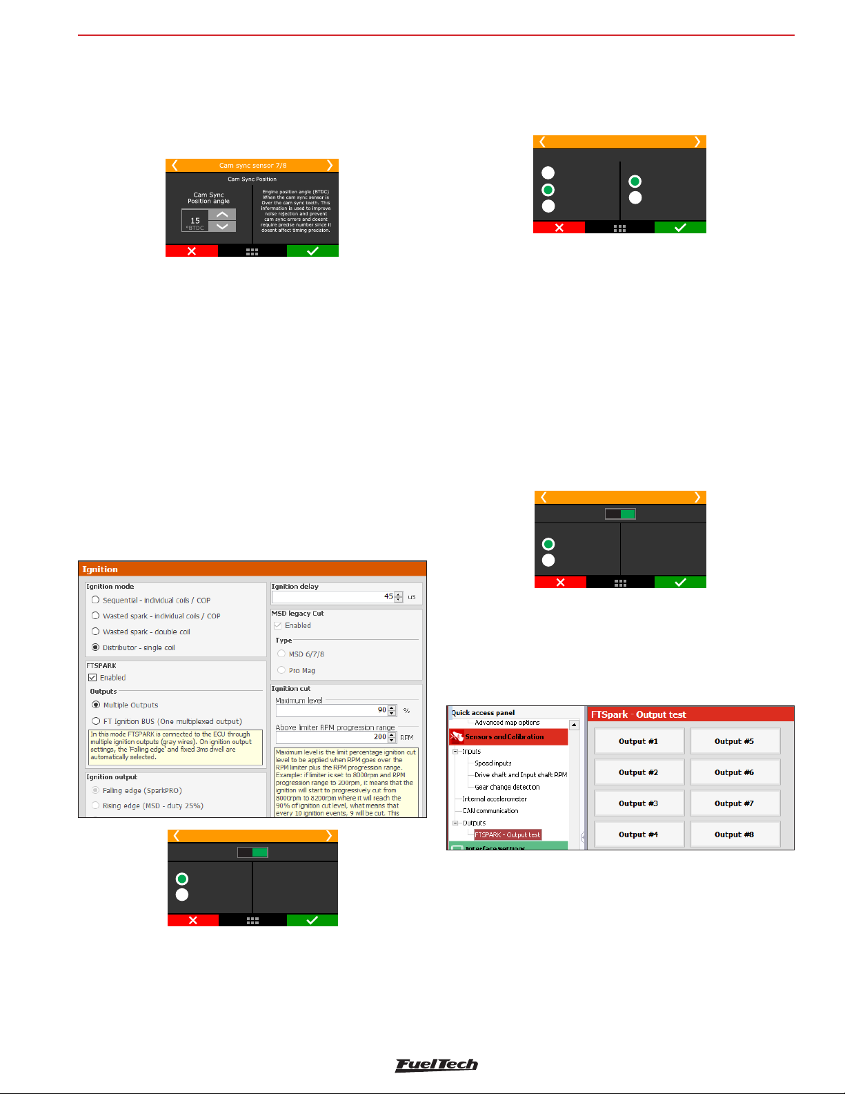
Engine settings
FT600
Cam sync position
Cam sync position is used to create a range within wich a Cam sync
signal is read and all others out of it are discarded, allowing the use
of a single reference on multi-toothed Cam sync pulleys.
7.3 Ignition
This menu sets everything related to the ignition control mode and
there is a “Default” mode (configurable through the ECU or PC) and a
“Custom” mode (configurable only through the PC). When the ignition
is set as “Disabled”, timing maps are unavailable and only the fuel
control is enabled. Gray outputs are free to be set up as injectors or
auxiliary outputs.
Default: this mode makes the options available the options that are
commonly used for the majority of engines, with standard firing order
tables and configurations.
Custom: this mode enables all the options related to the ignition
control, as customizable firing orders and angles, etc. When using
this mode, ignition configuration can only be done through a PC with
FTManager Software.
The option “distributor” means that the spark distribution will actually
be done by a distributor, with a single coil, regardless of the number
of cylinders. Only the ignition output #1 (gray #1) will be used to
control the ignition coil, the others are disabled.
Ignition 2/5
Ignition mode
Distributor
Wasted spark
Sequential
Double coil
Single coil
FTSPARK
Select the FTSPARK check box when using the fueltech FTSPARK
module and select the connection mode with it:
Multiple outputs: this is the conventional way of connecting FT
to any ignition module, using an ignition output to trigger each coil
(double or single). In this case one or more ignition outputs will be
connected to the FTSPARK.
FTIgnition BUS (one multiplex output): Select this option to enable
only one ignition output to send all the ignition trigger signals to the
FTSPARK via the FT Ignition BUS. In this way the other outputs that
would be used for ignition can be reallocated to other functions.
Ignition 3/7
Disabled Enabled
FTSPARK
Multiple outputs
FT ignition bus
multiplexed output.
Alterada
In this mode FTSPARK is
connected to the ECU
through multiple ignition
outputs (gray wires).
On ignition output settings,
the‘Falling edge’and fixed
3ms dwell.
Ignition 1/5
Disabled
Default
Custom
Enabled
This selection opens
allignition setup
parameters
Ignition Mode
Select if the ignition will be controlled in sequential (cam sync sensor
needed) or wasted spark modes or if a distributor will be used for
that control. There is also the wasted spark mode, where the coils
work in pairs.
Output Test
When the multiplexed output is selected, its possible to test the
FTSPARK outputs using a “test function” on the FTManager. To do so,
go to ‘Sensors and Calibration’ then ‘Outputs’ and select FTSPARK Output test.
Ignition output
Select the ignition output edge/mode.
Falling edge (SparkPRO): Select this option when using FuelTech
SparkPRO, M&W ignition, smart coils (integrated igniter, such as GM LS
coils). This mode has dwell control enabled. It’s important to know the
dwell requirements or “charge time” of your particular ignition coil(s).
23
Page 24
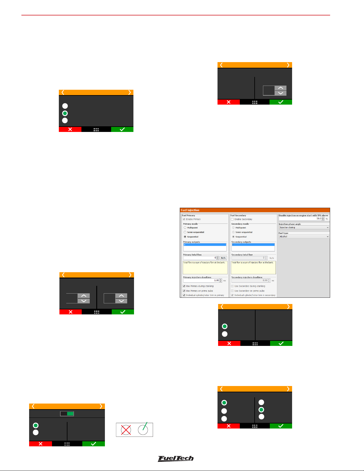
FT600
l
MSD Legacy Input
Engine settings
• Rising edge (MSD duty 50%): select this option when using MSD,
Crane, Mallory or other capacitive discharge ignitions (CDI). This mode
has a fixed 50% duty cycle signal.
• Rising edge (Honda Distributor): this option must only be selected
when using Honda distributor with stock igniter (the one that’s
integrated to the distributor). This mode has dwell control enabled.
Select this option only when using Honda OEM igniter and distributor.
Ignition 3/5
Ignition output
Falling edge (Spark )PRO
Rising edge (- duty 50%)MSD
Rising edge (Honda Distributor)
Ignition cut
The ignition cut maximum level is the percentage of ignition events
that will be cut to limit the engine RPM.
The RPM progression range acts like a smoothing for the ignition cut.
Example: rev limiter at 8000rpm, RPM progression range at 200rpm.
From 8000rpm the ignition cut level will gradually increase until it
reaches 90% cut at 8200rpm.
Percentages less than 90% may not keep the engine under the rev
limiter. Bigger RPM progression range tend to stabilize more smoothly
the rev limiter, but allows the RPM to pass the RPM set as rev limiter.
These numbers are valid to all kinds of ignition cut, with the exception
of time based compensations (time based RPM and driveshaft RPM/
wheel speed) and 2-step. These features have their own parameters.
For inductive ignition systems it is recommended to use 90% maximum
level and 200 RPM progression range. For capacitive system, like
MSD, it is recommended to use 100% maximum level and 1 RPM
progression range.
Ignition Delay time
That’s the delay time the ignition module has between receiving a
signal to spark and effectively spark at the plugs.
Time is given in microseconds (uS).
Ignition 5/5
Ignition delay time
Ignition delay time
compensation. ForMSD
and Spark , use 45us.PRO
40
us
7.4 Fuel injection
In this menu, all the options related to fuel settings must be configured.
Basic: This mode makes available the options that are commonly
used for the majority of engines, with standard injection angles and
configurations.
Advanced: This mode enables all the options related to the fuel
control, as customizable injection angles, etc. When using this mode,
fuel injection configuration can only be done through a PC with
FTManager Software. It is also possible to customize all the fuel tables
and RPM positions, adding RPM, TPS or MAP points according to the
engine needs
Ignition 4/6
Ignition cut
Maximum level
90
%
RPM progression range
200
RPM
External cut
This mode is only available when using a distributor and a MSD ignition
module. Enabling this option means the ignition cuts will be performed
by the MSD using the Legacy input they have.
To use MSD Legacy cut a FT600 white wire has to be connected
to the MSD Legacy right pin. By standard, White#10 is setup as
ignition cut.
When experiencing problems with the cut through MSD like no cut
at all or RPM limit always 500 RPM above what was setup, use the
other MSD pin.
Ignition 4/5
Disabled
MSD
Pro Mag
24
Enabled
External cut
Allignition cuts are executed
by module through a signa
MSD
sent by an White output to
the Legacy input. If thisMSD
is not selected, ignition
cut is done by 500FT
Connect a 500 white wireFT
to the pin on the right
Do not connect
pin on the left
Fuel injection 1/6
Basic
Advanced (PC)
This selection opens
all fuel injection
setup parameters
Fuel Banks: select primary and secondary (if used) banks control
mode.
Multipoint: All the injector’s outputs will fire at the same time, as
batch fire.
Fuel injection 2/6
Primary
Multipoint
Semi-sequential
Sequential
1 output
2 outputs
4 outputs
Page 25
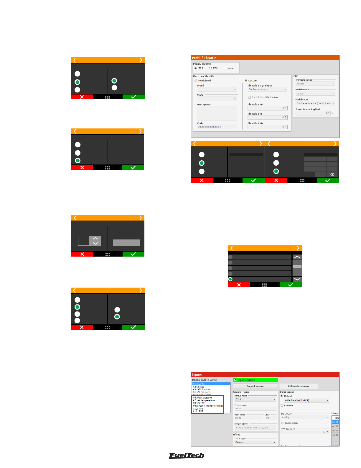
Engine settings
123
456
789
SF
FT600
Semi-sequential: in this mode, injectors are fired once per engine
revolution, at 0° and 360°, in pairs, according to the twin cylinders.
In a 4 cylinder engine, cylinders 1 and 4 will be fired at the same
time, then cylinders 2 and 3 at the same time.
Fuel injection 2/6
Primary
Multipoint
Semi-sequential
Sequential
2 outputs
4 outputs
Sequential: in this mode, each injector output fires only a single time
per engine cycle (720° on a 4 stroke). This mode is only available
when a cam sync sensor is properly set up.
Fuel injection 2/6
Primary
Multipoint
Semi-sequential
Sequential
Injector’s total flow
That’s the total flow of all injectors on the bank (primary or secondary).
This data is used to allow addition of some fuel tables in lb/hr I.e.
four 80 lb/hr injectors on primary bank have a total flow of 320 lb/
hr (80 x 4).
Fuel injection 3/6
Primary
Injectors total flow
320
lb/h
Total flow is a sum of injectors
flow at the bank.
Edit unit
Fuel type
Select the fuel used on the motor. This information is used to create
a better base map
Fuel injection 6/6
Fuel type
Pump gas
Race gas
E85
Alcohol
Fuel injector
phase reference:
Fuel injector
opening
Fuel injector
closing
7.5 Pedal/Throttle
Select the option “TPS” when using a mechanical throttle, driven by
cable.
Pedal / Throttle 1/9
Electronic Throttle code
None
TPS
ETC
0500020010002001
TPS
When using a throttle drives by cable with a potentiometer on the
throttle shaft select the TPS option.
Standard input for TPS sensor signal is #11, but it is possible to set
this input on any available input. Pedal/Throttle calibration must be
performed as shown in chapter 12.4
TP
Pedal / Throttle 2/9
White 7: Air temperature
White 8: Avaliable
White 9: Avaliable
White 10: Avaliable
White 11: Avaliable
Electronic throttle control ETC
First data to be inserted on the ECU when using electronic Throttle
is its code (not the throttle part number). This code is found on the
FTManager Software. If your throttle is not on the list, please, contact
our tech support to check compatibility first.
Pedal / Throttle 1/9
None
TPS
ETC
Tinput selection: default white #11 on 400
Electronic Throttle code
0500020010002001
0
Fuel injection phase reference
Select if the Fuel injection phase angle table will be based on the
injectors opening or closing. The angular distance is the measure
between the ignition TDC of each cylinder and the moment the injector
should open or close
Fuel injector opening: in this option it is only possible to know the
angle the injector will open, but, its closure will vary according to
injection time and RPM, this means that, depending on these factors,
the fuel injection may still be occurring even after the intake valve
has closed
Fuel injector closing (default): This is the most commonly used
option as the fuel injection always occurs before the end of the intake
cycle, no matter the injection time or RPM.
Throttle position sensor input
If the map is generated in the FTManager software the ETC inputs
will be automatically allocated and can be checked in “Sensors and
Calibration” menu, then “Inputs”.
25
Page 26
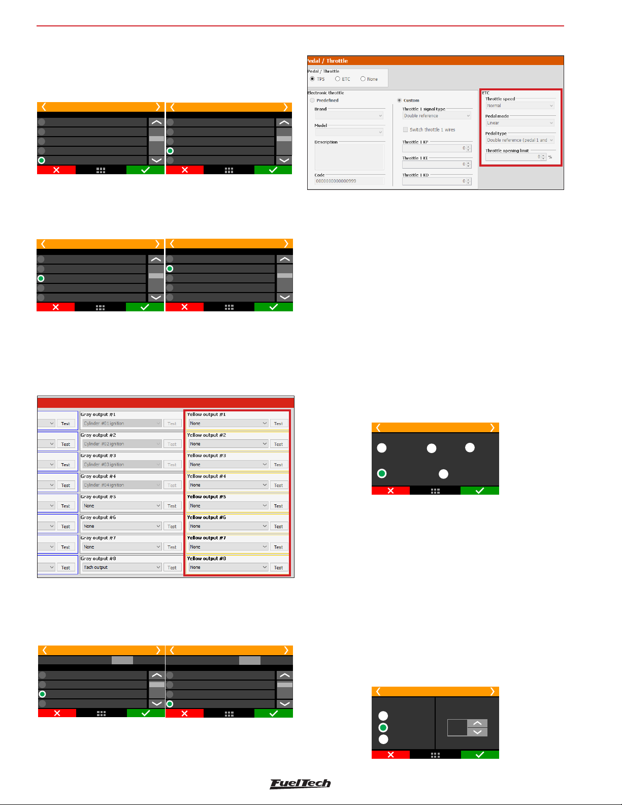
FT600
Engine settings
After inserting the Throttle code, set the input that will be connected
to the throttle position sensor, usually there are two signals on the
throttle. Standard inputs are wires white #11 (Throttle signal #1A)
and white #10 (Throttle signal #1B).
Throttle #1A input selection: default white #11 on 400FT
Pedal / Throttle 2/9
White 7: Air temperature
White 8: Available
White 9: Available
White 10: Available
White 11: Available
Input for Throttle signal #1A
Throttle #1B input selection: default white #10 on 400FT
Pedal / Throttle 3/9
White 7: Air temperature
White 8: Available
White 9: Available
White 10: Available
White 11: Throttle #1A
Input for Throttle signal #1B
Now, setup the inputs that will be connected pedal #1 and pedal #2
position sensors. The standard inputs are wires white #9 (pedal #1)
and white #8 (pedal #2).
Pedal #1 input selection: default white #9 on 400FT
White 7: Air temperature
White 8: Available
White 9: Available
White 10: Throttle #1B
White 11: Throttle #1A
Pedal / Throttle 4/9
Pedal #2 input selection: default white #8 on 400FT
Input for Pedal signal #1 Input for Pedal signal #2
Pedal / Throttle 5/9
White 7: Air temperature
White 8: Available
White 9: Pedal #1
White 10: Throttle #1B
White 11: Throttle #1A
Electronic throttle control motor outputs
When generating the map in the FTManager the Yellow #3 and #4
will be selected to ECT motor control.
The next parameter to be setup is the Throttle speed.
There are five control modes:
Normal: normal throttle response little bit faster than the stock ECU.
Fast: fast throttle response.
Smooth: smoother control mode, used on street cars and automatic
transmissions.
Smooth when cold and normal when hot: changes the control
mode according to the engine temperature, starts with smooth mode,
and then changes to normal mode automatically.
Smooth when cold and fast when hot: changes the control mode
according to the engine temperature, starts with smooth mode, and
then changes to fast mode automatically
Select the outputs that will control the two wires from the throttle
motor. By standard they are yellow #3 (motor 1A) and yellow #4
(motor 1B). In case these outputs are already being used by another
kind of control, use outputs yellow #1 and yellow #2
Pedal / Throttle 6/9
Test output:
ETCmotor #1A output selection: default yellow #3
Yellow 1: Available
Yellow 2: Available
Yellow 3: Available
Yellow 4: Available
Test
Input for throttle motor 1A control
Pedal / Throttle 7/9
Test output:
ETCmotor #1B output selection: default yellow #4
Yellow 1: Available
Yellow 2: Available
Yellow 3: motor 1AETC
Yellow 4: Available
Test
Input for throttle motor 1B control
Pedal / Throttle 8/9
Electronic Throttle speed
Normal
Smooth when cold and
normal when hot
Fast
Smooth
Smooth when cold and
fast when hot
Operation mode: this parameter changes the ratio between the
pedal and the throttle.
Linear: this mode has a 1:1 ratio between pedal and throttle.
Progressive: recommended for street cars.
Aggressive: throttle/pedal ratio is 2:1. When pressing 50% pedal,
throttle is already on 100%.
The last parameter to be configured is an opening limiter, very useful
to limit the engine power by the throttle.
Use 100% when no safety limit is wanted.
Pedal / Throttle 9/9
Operation mode
Linear
Progressive
Aggressive
Throttle opening
limit
100,0
%
26
Page 27
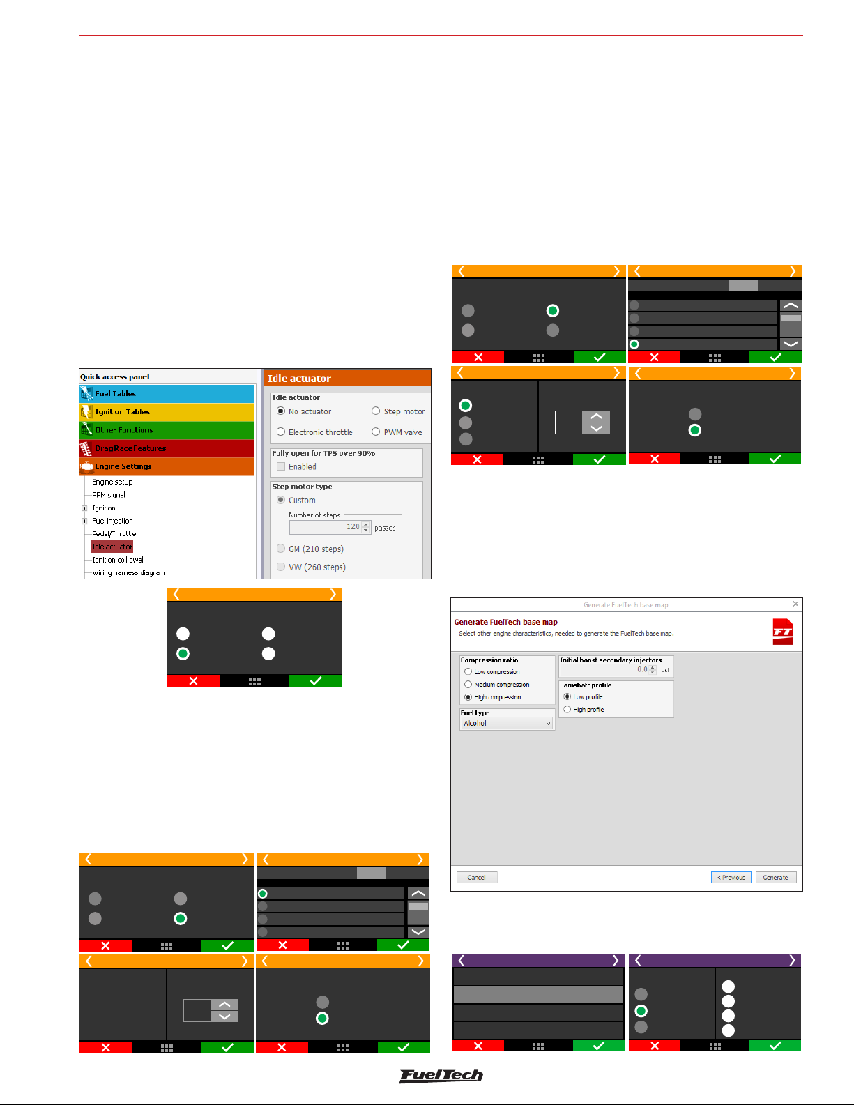
Engine settings
FT600
7.6 Idle actuators
This menu allows you to select the idle actuator used on the engine
and the outputs that will control it. After this quick setup, the idle speed
parameters must be done according to chapter 19.2.
An important tip is that, when selecting “No Actuator”, it is still possible
to control idle speed by ignition timing as configured in the “Other
Functions” then “Idle Speed” menus. If any kind of actuator is selected,
the idle speed by timing control is automatically enabled. This happens
because the idle speed control was specially developed for this FT600
, integrating the timing control with the actuator reactions
Electronic throttle
Select this option, then go to “Idle speed control settings”, under
“Other Functions” menu.
Check Chapter 19.2 of this manual for more details.
Stepper motor
In this option, the four yellow outputs are used. It is necessary to
inform which output controls which step motor output and the step
motor type. There are predefined actuators for VW and GM models
(number of steps) and a “Custom” mode that allows the configuration
of steps. As there are many variables in the manufacturing process,
if you’re experiencing difficulties at idle tuning, check the “Custom”
mode and change the number of steps. In some GM step motors, 190
is the correct number. For some VW step motors, 210 works better.
The option “Fully open for TPS over 90%” fully opens the idle valve
when TPS is above 90%, increasing the air admitted.
Idle actuator 1/4
None
Electronic throttle
Idle actuator 3/4
Stepper motor type
Custom
GM (210 steps)
VW (260 steps)
Stepper motor
PWMvalve
Numbers of
steps
280
Yellow 1: Step motor 1A
Yellow 2: Step motor 2A
Yellow 3: Step motor 1B
Yellow 4: Step motor 2B
Idle actuator 2/4
Test output:
Output selection
Idle actuator 4/4
Fully open actuator for over 90%TPS
Enabled
Disabled
Test
Idle actuator 1/4
None
Electronic throttle
Stepper motor
PWMvalve
PWM Valve
After selecting this option, it will be necessary to set up the output
connected to the valve and the control frequency. Small valves usually
use up to 2000Hz. For big valves use around 100Hz. If your valve
becomes noisy, that means the control frequency is lower than what
the valve requires. In this case, increase the control frequency.
Be aware that the only outputs that can control these kinds of valves
are the yellow ones.
Idle actuator 1/4
None
Electronic throttle
Stepper motor
PWMvalve
Yellow 1: va lvePWM
Yellow 2: Available
Yellow 3: Available
Yellow 4: Available
Idle actuator 2/4
Test output:
Output selection
Test
7.7 FuelTech base map
With the “Engine Setup” menu fully set up, the next step is to generate
the FuelTech base map, a function that generates fuel and ignition
maps to be used as a start point for the engine tuning.
The window below is displayed at the end of configuration assistant
in the FTManager:
When generating a base map in the touchscreen interface, the
informationwill be displayedsimilar to the images below:
Idle actuator 3/4
Reference: Smallvalves
usually uses up to 2000Hz.
Bigger valves usually uses
between 50 and 100Hz.
Frequency
1700
Hz
Idle actuator 4/4
Fully open actuator for over 90%TPS
Enabled
Disabled
File Manager 2/2
Edit map file name
Generate FuelTech base map
Copy map to another file
Erase file
FuelTech default map
Compression ratio
High
Medium
Low
Fuel type
Pump gas
Race gas
E85
Ethanol
27
Page 28
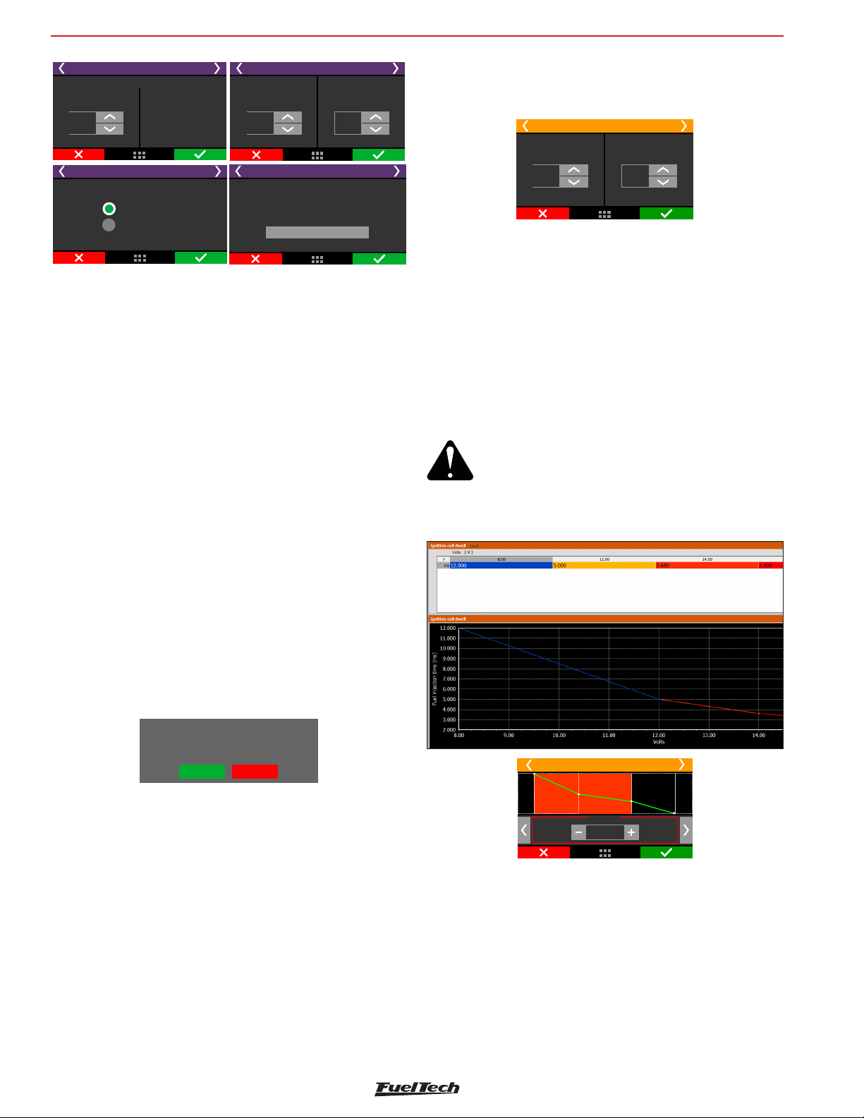
FT600
Engine settings
FuelTech default map
Injectors total flow
320
lb/h
FuelTech default map
Camshaft profile
Primary
Total flow is the sum of injectors
High profile
Low profile
flow at the bank.
Example: 4 injectors with
80 lb/h has 320 lb/h
total flow
FuelTech default map
Secondary injectors
total flow
640
lb/h
FuelTech default map
This operation will erase
previous settings.
Are you sure?
Generate FuelTech base map
Initial boost for
secondary injectors
0.50
bar
Compression ratio: used to correctly estimate the timing tables. A
low, medium or high compression ratio is defined according to the fuel
used on the engine and if it is turbocharged or naturally aspirated.
I.e., a 10:1 compression ratio for a naturally aspirated engine using
ethanol is considered a “low compression ratio”. The same ratio for a
turbocharged engine running gasoline will be “high”.
Primary and secondary injector’s total flow: select the flow of
the injectors responsible for the naturally aspirated/low load range
of the engine.
Initial boost for secondary injectors: Here is where you will set the
pressure you want the secondary bank to start opening, usually under
boost. This option is only shown when using two banks of injectors
general values; check this parameter with the injector manufacturer.
In the FTManager, this parameter is in the Injection menu in “Engine
Settings”.
Fuel injectors deadtime
Secondary
0,800
ms
1,000
ms
Primary
7.9 Ignition Dwell
This option sets the ignition coil charging time. There is a dwell table
because the charging time varies according to the battery voltage,
especially in vehicles that do not have alternator.
Usually, the lower the voltage, the higher the dwell time has to be set.
Smart coils (coils with internal igniter) demand lower charging
times. These are general values; check this parameter with the coil
manufacturer.
WARNING:
When using MSD ignition modules, it’s not
possible to control the Dwell time. In this case,
the coil’s charging time is calculated by th MSD
module.
Camshaft: select the characteristic of the engine camshaft. When
selecting high profile camshaft, all injection tables from absolute
vacuum until -4.3psi are equal, as this type of camshaft does not have
steady vacuum at idle speed. When selecting low profile camshaft,
the injection times at vacuum phase are filled up in a linear manner.
Now, click the button “Generate FuelTech base map”. The ECU will
show a warning that the current map will be overwritten by the
FuelTech base map.
TPS not calibrated!
Do you want to run
the calibration wizard?
Yes No
A notice about throttle/pedal calibration will be displayed. Click Yes
and you will be redirected to the calibration screen.
The Chapter 15.1 has detailed information about the calibration.
The next chapters explain other functions contained in the Engine
Settings menu.
7.8 Fuel injectors deadtime
All fuel injectors, as they are electromechanical valves, have an opening
inertia, which means that there is a “dead time”, a moment in which
the injector has already received an opening signal, but still has not
started to inject fuel. This parameter considers, as a standard value,
1.00ms for high impedance fuel injectors. For low impedance injectors
using Peak and Hold driver, set the deadtime to 0.60ms. These are
Ignition dwell
12,0 V
ms
3,600
7.10 Ignition energy
This menu allows the user to program the ignition energy of the
FuelTech FTSPARK ignition module.
This 3D table relates engine RPM, MAP (boost/vacuum) and the
desired mJ (milijoules) value.
The ignition energy control is done by connecting both equipments
(FT ECU and FTSPARK) by their CAN network.
28
Page 29
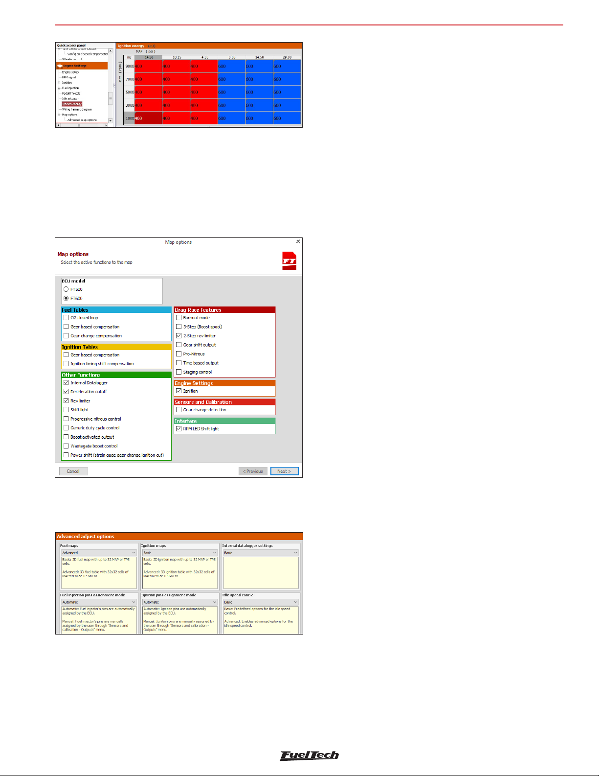
Engine settings
7.11 Map options
Select the ECU model that is connected to the PC and which features
will remain visible on the active map.
This makes navigation through the software much easier by hiding
unused menus.
In case you need to make an option visible again, just go to Engine
Settings and then Map Options.
FT600
Fuel injection pins assignment mode
• Automatic - fuel injector’s pins are automatically assigned by the
ECU.
• Manual - fuel injector’s pins are manually assigned by the user
through “Sensors and Calibration - Outputs” menu.
O2 closed loop mode
• Basic - Predefined options for the O2 closed loop.
• Advanced - Enables advanced options for the O2 closed loop.
Ignition
Ignition maps
• Basic - ignition maps are in a 2D table that relates MAP x timing
or TPS x timing.
• Advanced - 3D MAP x RPM or TPS x RPM timing table with
32x32 cells.
Ignition pins assignment mode
• Automatic - ignition pins are automatically assigned by the ECU.
• Manual - ignition pins are manually assigned by the user through
“Sensors and Calibration - Outputs” menu.
7.12 Advanced map options
There are some options that are only available through FTManager. To
access them, go to “Engine Settings” Menu:
RPM settings
• Basic - Pre-defined voltage detection levels for VR crank and cam
sensors.
• Advanced - The adjustment of voltage levels for detection of
VR sensors in advanced mode allows the conditioning of non
standard crank/cam signals, especially when they’re spliced with
the stock ECU.
Other Function
Internal Datalogger
• Basic: fixed sampling rates.
• Advanced: configured sampling rates per channel.
Idle speed control
• Basic - predefined options for controlling idle. Meet 99% of the
vehicles.
• Advanced - releases advanced options such as PID control, target
approach RPM, deadband, approach RPM, etc.
Wastegate boost pressure control
• Basic - predefined options for the wastegate boost pressure
control.
• Advanced - enables advanced options for the wastegate boost
pressure control.
Injection
Fuel maps
• Basic - fuel maps are in a 2D table that relates MAP x injection
time or TPS x injection time.
• Advanced - 3D MAP x RPM or TPS x RPM fuel table with 32x32
cells.
29
Page 30
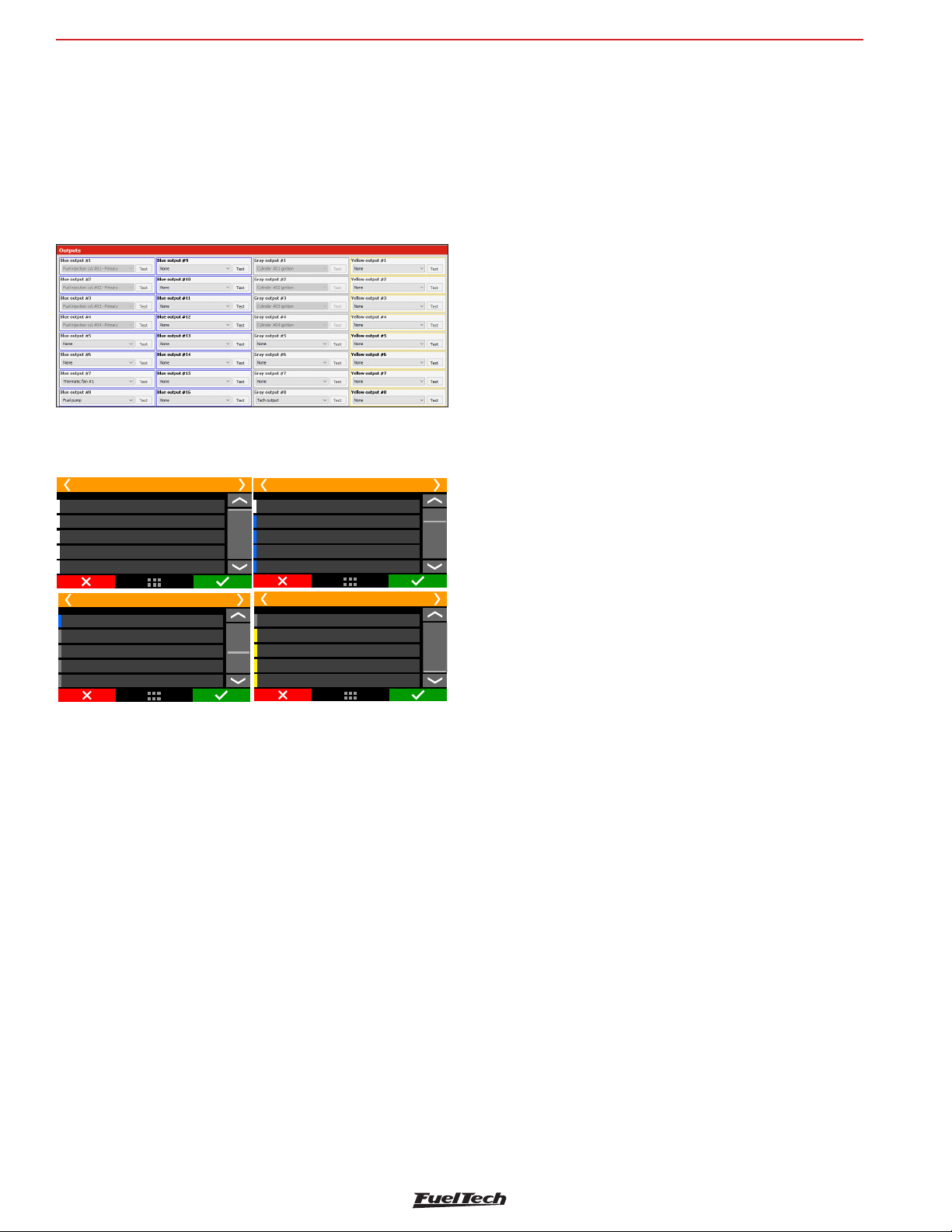
FT600
Electrical installation
8. Electrical installation
As FT600 wires are fully configurable according to the installation
needs, it is very important that the step by step guide shown on chapter
5 is followed before starting the electrical installation. This way the
wiring harness connection table is automatically filled as shows the
example below:
In the FTManager, to check all the inputs and outputs, go to “Sensors
and Calibration” menu, then “Inputs” or “Wiring harness diagram”.
Through the touchscreen interface, you can access this function in the
“Engine Settings”, then “Wiring harness diagram”.
Wiring harness diagram
White 1: O2 sensor #1
White 2: 2-step
White 3: Air conditioning
White 4: Oil pressure
White 5: Engine temperature
Wiring harness diagram
Blue 8: Shift Alert
Grey 1: Ignition - cylinder 1
Grey 2: Ignition - cylinder 2
Grey 3: Ignition - cylinder 3
Grey 4: Ignition - cylinder 4
White 11: TPS
Blue 1: Primary fuel inj. - cylinder 1
Blue 2: Primary fuel inj. - cylinder 2
Blue 3: Primary fuel inj. - cylinder 3
Blue 4: Primary fuel inj. - cylinder 4
Grey 8: Tachometer output
Yellow 1: valvePWM
Yellow 2: Fuel pump
Yellow 3: Electric fan #1
Yellow 4: Available
Based on this information, you can start the electrical installation that
must be done with the ECU disconnected from the harness and the
battery disconnected from the vehicle. It is very important that the
cable length as short as possible and that unused parts of wires are
cut off.
Choose an appropriate location to affix the module inside the car, and
avoid passing the cable wires close to the ignition wires and cables,
ignition coils and other sources of electric noise.
DON’T EVER, under any circumstance, install the ECU near ignition
modules in order to avoid the risk of interferences.
Electric cables must be protected from contact with sharp edges on the
vehicle’s body that might damage the wires and cause short circuit. Be
particularly attentive to wires passing through holes, and use rubber
grommets/protectors or any other kind of protective material to prevent
any damage to the wires. At the engine compartment, pass the wires
through places where they will not be subject to excessive heat and
will not obstruct any mobile parts in the engine.
Wiring harness diagram
Wiring harness diagram
• 12V for sensors: use a 24 AWG wire from the same 12V wire that
feeds the ECU (Main Relay). Example: Hall Effect sensors, pressure
sensors, speed/RPM sensors, etc. This wire cannot be shared with
the positive wire that powers coils, fuel injectors or other actuators.
• 12V for fuel injectors: use a 14 AWG wire connected to a 40A
relay. Protection fuse must be chosen according to the peak current
of the fuel injectors plus a 40% safety coefficient.
Example: for up to 4 injectors that draw 1A of current per injector
on primary bank, and 4 injectors that draw 4A of current per injector
on secondary bank: (4x1A)+(4x4A)=20A + 40% = 28A. Use a
30A fuse.
• 12V for coils, fuel pump and other high power actuators: use
a wire with at least 14 AWG connected to a relay and a fuse correctly
dimensioned according to the actuator current draw. When using
individual coils (COP), it is recommended a 70A or 80A relay.
NEVER share the 12V that feeds injectors, coils or other accessories,
because, after shutting the engine off, there is a risk of reverse current
that may damage a sensor or the ECU.
Black wire - Battery’s negative
This wire is responsible for signal ground to the ECU so, it must be
connected straight to the battery’s negative terminal, with no
seams. Under no circunstances, shold this wire be connected to
the vehicle chassis or split with the ECU black/white wire (power
ground). This will cause electromagnetic interference and other
problems hard to diagnose and solve.
The black wire must have permanent contact with the battery’s negative
terminal, never being connected to switches, car alarms or others. To
turn a FuelTech ECU off, the red wire should be switched on and off.
• Attach the negative wires to the battery terminal use ring terminals
and avoid soldering them. A well crimped terminal has better
resistance than a soldered one. Besides that, solder makes the
joint stiffer, and less resistant to vibration, typically found in
automotive applications.
• Use a crimping tool and insulate the wire with insulating tape or
heat shrink tubing.
• If there’s a need to solder the wire to the terminal, check it`s
resistance after the solder, it should be lower than 0.2 Ohms.
NOTE: If corrosion is found (green/White powder) on the battery
terminals, clean it with a wire brush and baking soda or contact cleaner
spray. Double check the terminal holder and replace it if necessary.
Check resistance after the cleaning, it should be lower than 0.2 Ohms.
Green/Black wire - Negative for sensors
(TPS, air temp., pressure, rpm, distributor, etc.): It is vital to use sensors
ground straight to the battery’s negative terminal. Connecting them
to chassis may cause electromagnetic interference, wrong readings
or even damage to the sensors.
Red wire - 12V input
The 12V input to FuelTech ECU, this wire must be connected to 12V
from a relay (Main Relay) and cannot be shared with the positive wire
that powers coils, fuel injectors or other actuators.
30
Black/White wire – power ground
These are the ECU power ground wires. They must be connected to
the engine block or head in a place with a good electrical contact.
The same shield that goes from the chassis to the battery’s negative
terminal is a good contact point.
Page 31
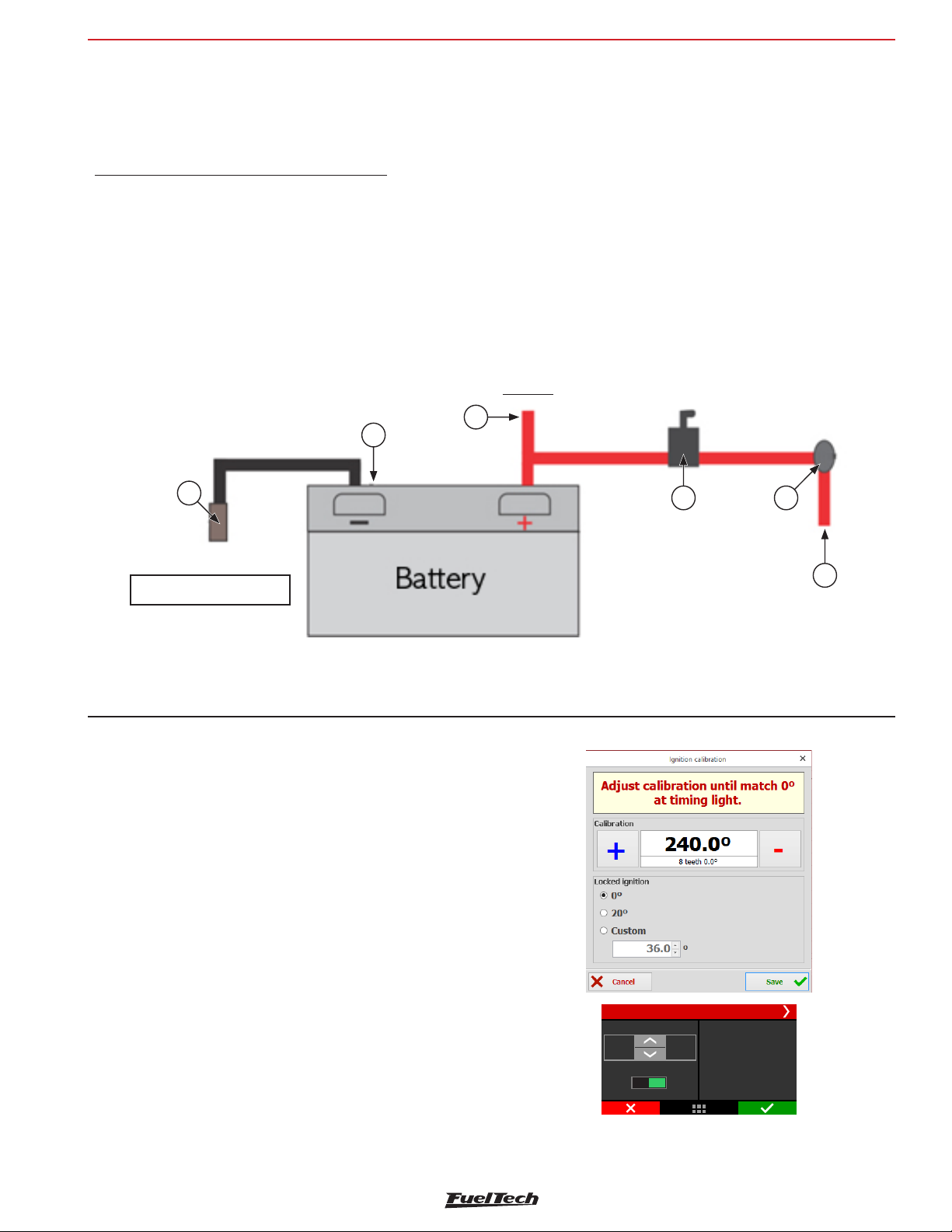
FT600 connection on previous FT installation
FT600
The three power grounds (24 and 16-way connectors) must have
permanent contact with the engine block/head, never being connected
to switches, car alarms or others. To turn a FuelTech ECU off, the red
wire should be switched on and off.
Power ground to ignition modules (SparkPRO, etc.), Peak and Hold
drivers, relays and other accessories, must be connected to the same
point, at the engine block/head.
A good test to check if the power grounds are with good connection
is, using a tester, to measure the resistance between the battery’s
negative terminal and the chassis ground. Connect the red probe on
the chassis point that the shield is connected and the black probe
on the battery’s negative. With the tester on the 200ohms range, the
resistance measured must be below 0.2 Ohms.
Remember to touch both probes to check its resistance. This reading
must be subtracted from the first reading to found the correct value.
3
2
1
OBS: it is very important to check the shield that connects the engine
block to the chassis and to the battery. If this shield is defective, replace
it by a new one, as it may cause serious damage to the ECU and its
sensors. For this reason, we recommend the use of two os these
shields two of these shields.
Main switch installation (optional) – important tips
Main switches have been used for a long time in competition vehicles
for safety purposes in case of an accident. Just like any other electric
accessory, there’s a correct way to install it:
The main switch cannot be connected to ground or power
ground, under any circumstances!! This is the most common error
by installers and, usually costs hours of work to fix all the problems that
it cause. All of this without counting the huge possibility of damaging
all the electronic accessories on the vehicle. The main switch must
ALWAYS control the battery’s positive (12V).
4 5
FT black/white wire must be
connected to engine head
1 - Shield connecting battery negative to chassis and engine;
2 - FT black wire Battery negative;
3 - Positive wire to alternator;
9. FT600 connection on FT500 installation
FT600 can be installed on vehicles which already use FT500/
FT500LITE, with no need to rewire everything. However, a few points
must be checked or modified.
The best option is to make a new installation, using the FT600 harness,
according to the recommendations here brought.
However, if to rewire is not possible, there is an other alternative: to
cut the FT500 connectors and wiring them as shown below.
In order to do so a FT600 connector kit is needed (sold separately).
9.1 Ignition calibration
The ignition calibration screen on FT600 has the same parameters
that previous FT ECUs, the difference is that they are in the same
screen. After calibrating the ignition, the 1st tooth index position is
automatically changed on the “Engine setup” menu.
When using distributor, the ignition must be calibrated on this screen,
instead of turning the distributor.
4 - Main switch;
5 - Ignition Switch;
6 - Switched 12V;
1,23 0
°
Lock timing
0° 20°
Ignition calibration
23
Teeth
Adjust calibration
-03, º
until match 20 at
6
timing light
Ignition calibration screen: FTManager in FT600
31
Page 32
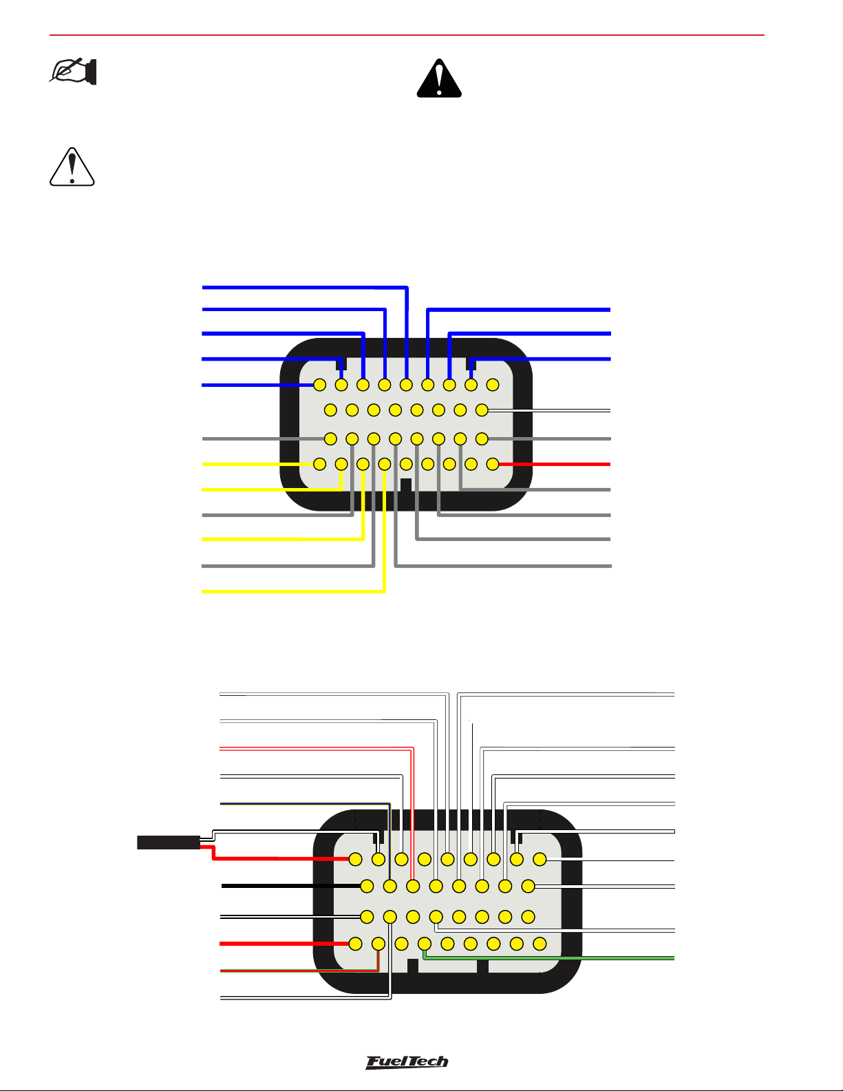
FT600
Battery negative
White magnetic RPM-
Yellow/Blue - CAN_A_LOW
White/Red - CAN_A_HIGH
White CA sync signal inputM-
White input#6-
White input#1-
White input#2-
White input#8-
White input#3-
White input#9-
White input#4-
White input#10-
White input#5-
Red - 12V from relay
Black/white
Green/Red -
Black/White - chassis ground
Black Shielded Cable
White input#7-
Red RPM signal input-
signal sensor
Ground chassi
5V output sensors
12
3
4
5
6789
10
11 12
13
14
15 16
17
18 19 20
21 22
23 24 25
26
27
28
29
30 31 32 33 34
White -1input#1
Green/Black Ground for Sensors
Blue output#8
Black/white -
Yellow output#1
Gray output#1
Yellow output#2
Gray output#2
Yellow output#3
Gray Output#3
Yellow output#4
Gray output#4
Gray output#5
Gray output#6
Gray output#7
Gray output#8
Red - 12V
from relay
Chassi Grounds
1
3
4
5
6789
10
11 12
13
14
15 16
17
18 19 20
21 22
23 24 25
26
27
28
29
30 31 32 33 34
2
Blue output#5
FT600 connection on previous FT installation
NOTE:
In order to avoid any kind of damage to your
installation, cut one wire at a time, crimp it and
install it in the proper position.
IMPORTANT:
In the rear of both connectors the positions are
sequentially numbered. The following diagrams show
it considering a back view where the pins must be
inserted.
A-Connector diagram - using FT500 wires
Blue output#4
Blue output#3
Blue output#2
Blue output#1
Wires from FT500 harness to be
crimped on FT600 plug
WARNING:
Check carefully and identify each connector:
A-Connector: 3 reference notches
B-Connector: 4 reference notches.
Blue output#6
Blue output#7
Wires from FT500 harness to be
crimped on FT600 plug
B-Connector diagram - using FT500 wires
32
Wires from FT500 harness to be
crimped on FT600 plug
Wires from FT500
harness to be
crimped on FT600
plug
Page 33
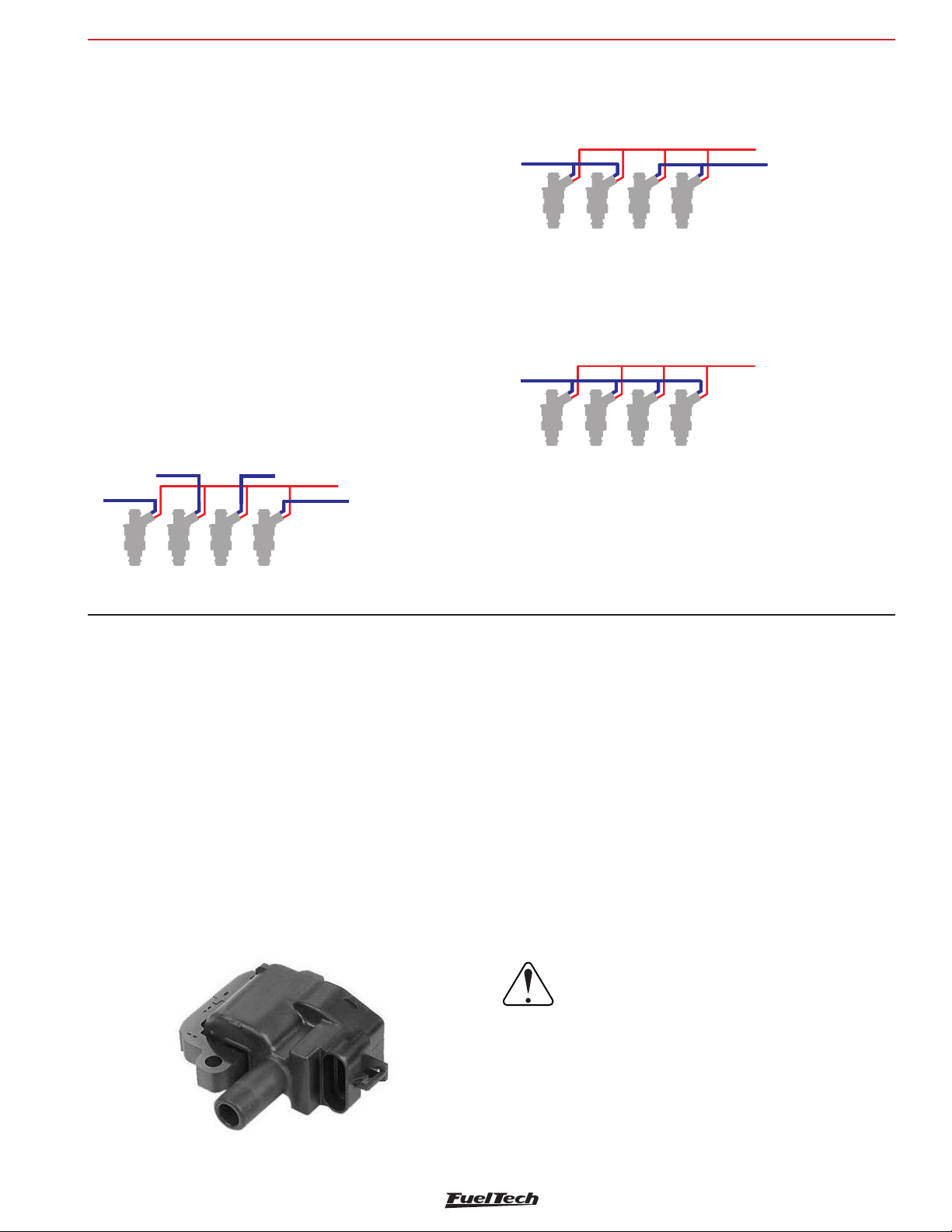
Switched 12V (Injectors relay)
Switched 12V (Injectors relay)
Switched 12V (Injectors relay)
Fuel injectors
FT600
10. Fuel injectors
A FT600 has 8 outputs to control fuel injectors (blue wires #1 to
#8). Each one of them can control up to 6 injectors with internal
resistance above 10 Ohms (saturated injectors) or up to 4 injectors
with internal resistance above 7 Ohms. Using a Peak and Hold driver,
this capacity varies according to the output and the Peak and Hold
current control (2A/0,5A, 4A/1A or 8A/2A).
In situations where more than 8 outputs are needed, the gray or yellow
outputs can be set as injector outputs. In this case, the use of a Peak
and Hold driver for these outputs is mandatory.
Injectors can be triggered in multipoint, semi sequential or sequential
modes.
Examples of 4-cyl engines running high impedance injectors
• Individual triggering: each blue output controls a cylinder. This
is the most recommended connection cause is the only one that
allows individual per cylinder fuel compensations, amongst other
functions.
Blue #2
Blue #1
Blue #3
Blue #4
• Two injectors per channel: blue output #1 controls injector of
cylinders 1 and 4. Blue output #2 controls injectors of cylinders
2 and 3
Blue #1
cyl.1
cyl 4.
• Four injectors per channel: use this connection only for
compatibility with previous generation FT ECUs.
Blue #1
cyl.1
cyl.2
Even with each output controlling only one injector it is possible to
change the triggering mode to multipoint (batch fire), semi sequential
(outputs triggered in pairs) or sequential.
cyl 2.
cyl.3
cyl 3.
cyl.4
Blue #2
c l.1y
11. Ignition
A FT600 has 12 ignition outputs that can be used according to the
needs of the project, controlling a distributor or a crank trigger.
Ignition with distributor
When using this ECU with a distributor, the only active ignition output
is gray #1. This wire must trigger an ignition module or a coil with
integrated igniter. When MSD configured it’s utilized Yellow#1.
Coil with integrated igniter (smart coil)
They are coils with at least 3 pins and only one spark plug wire
output. This kind of coil (inductive) must be set as “Falling dwell”
in the “Ignition output” menu. In case of selecting the wrong output
type, coil will be damaged.
A - Ground (near coil) / igniter;
B - Signal Ground;
C - 5V signal from sequencer;
D - Switched;
FuelTech SparkPRO-1 with coil without integrated igniter
(dumb coil)
The FuelTech Spark PRO-1 module is an high energy inductive igniter
which has an excellent cost/benefit and can be used with any 2-wire
dumb coil (without internal igniter). Coils with primary least possible
resistance are recommended for maximum SparkPRO-1 potential. The
minimum resistance of the coil primary should be 0.3 ohms, below
this the SparkPRO will be damaged.
Try to place SparkPRO-1 as close as possible to the coil.
Warning about the SparkPRO-1: An excessive
charging time (Dwell) can damage the SparkPRO
and the coil. It is recommended to use a Dwell
map with 6ms at 8V, 4ms at 10V, 3.60ms at 12V
and 3.00ms at 15V and check coils temperature
at the beginning.
33
Page 34
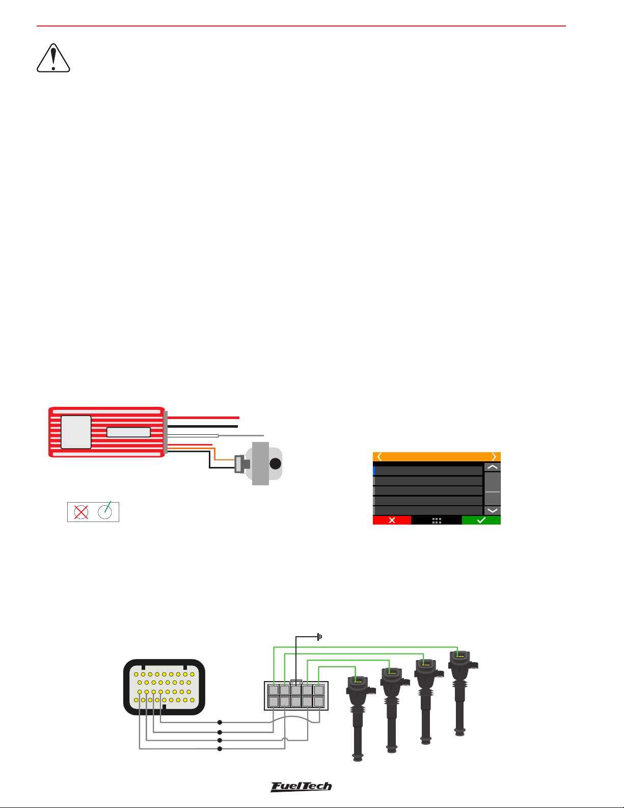
FT600
Channel input2
Channel input3
Channel input4
Power ground - engine head
Channel output4
Channel outuput2
Channel output1
Channel output3
CIL.4
CIL.2
CIL.1
CIL.3
Con ector An
SparkPRO-4
Gray output #1
Gray output #2
Gray output #3
Gray output #4
18 19 20
21 22
Ignition
IMPORTANT:
In the “Ignition” menu, select the ignition output
as “Falling dwell”. In case of selecting the wrong
output type, coil will be damaged.
Capacitive discharge ignition module (MSD 6A, MSD 7AL,
Crane, Mallory)
FuelTech’s ignition output must be connected to the MSD ignition
module, (usually, the white wire is the points input). When using a MSD
ignition box, the yellow #1 is automatically set up as ignition output.
The installation of ignition modules must always follow what is indicated
by its manufacturer in the instructions manual. This ignition module
will receive a Points signal from FuelTech. Ignition coil must follow the
ignition module manufacturer recommendations as well.
Important Notes:
• The module must be placed as close as possible to the ignition
coil, and never inside the car, in order to avoid the risk of
interference with electronic devices.
• The length of the wires that connects the ignition module to the
ignition coil must be as short as possible.
• In “Ignition Setup,” select the output “Rise (CDI)”.
• It is not possible to control the ignition Dwell when using this
type of module.
• To use the ignition cut through MSD, check Chapter 7.3
• When experiencing problems with the cut through MSD like no
cut at all or RPM limit always 500 RPM above what was setup,
use the other MSD pin.
Ignition with crank trigger
When controlling the ignition in distributor less systems, wasted spark
or individual coils per cylinder are needed. In this case, coils are
triggered by different outputs, according to the number of cylinders.
Ignition outputs (gray wires) are triggered according to the firing order
set up on the ECU
Example: 4 cylinder engine with individual coils:
Gray outputs are selected automatically, according to the number of
cylinders.
Gray wires that will not be used for ignition control can be set up as
injectors outputs (Peak and Hold driver is mandatory) or auxiliary
outputs (relay needed).
Individual coils – electrical connections
On FT600 , these connections must be done by matching the output
number with the cylinder number:
• Ignition output #1 controls cylinder #1 coil;
• Ignition output #2 controls cylinder #2 coil;
• Ignition output #3 controls cylinder #3 coil.
Positive Battery (Large Red)
ground of head (large black)
Obs.: Input “Magnetic Pickup”
not utilized
MSD Legacy Input
Connect a 500 white wireFT
to the pin on the right
Do not connect
pin on the left
input “Points” (White)
Positive Switch 12V
Orange (Positive Coil)
Black (Negative Coil)
Ignition output Gray 1
+
-
• When using MSD ignition modules with a distributor, it is
necessary to connect a FuelTech white wire to the MSD Legacy
input. Doing so improves the response of timing control, which
is especially necessary when using Drag Race Features.
5
3
6789
4
12
10
2627282930 31 32 33 34
11 121314
15 16
23 24 25
17
10
5
9
When working with dumb coils, an external ignition module must be
used (as the FuelTech SparkPRO). In this case, ignition outputs from
FT600 are connected to the ignition module inputs.
Wiring harness diagram
Blue 8: Shift Alert
Grey 1: Ignition - cylinder 1
Grey 2: Ignition - cylinder 2
Grey 3: Ignition - cylinder 3
Grey 4: Ignition - cylinder 4
6
78
1
34
2
34
Channel input1
Page 35
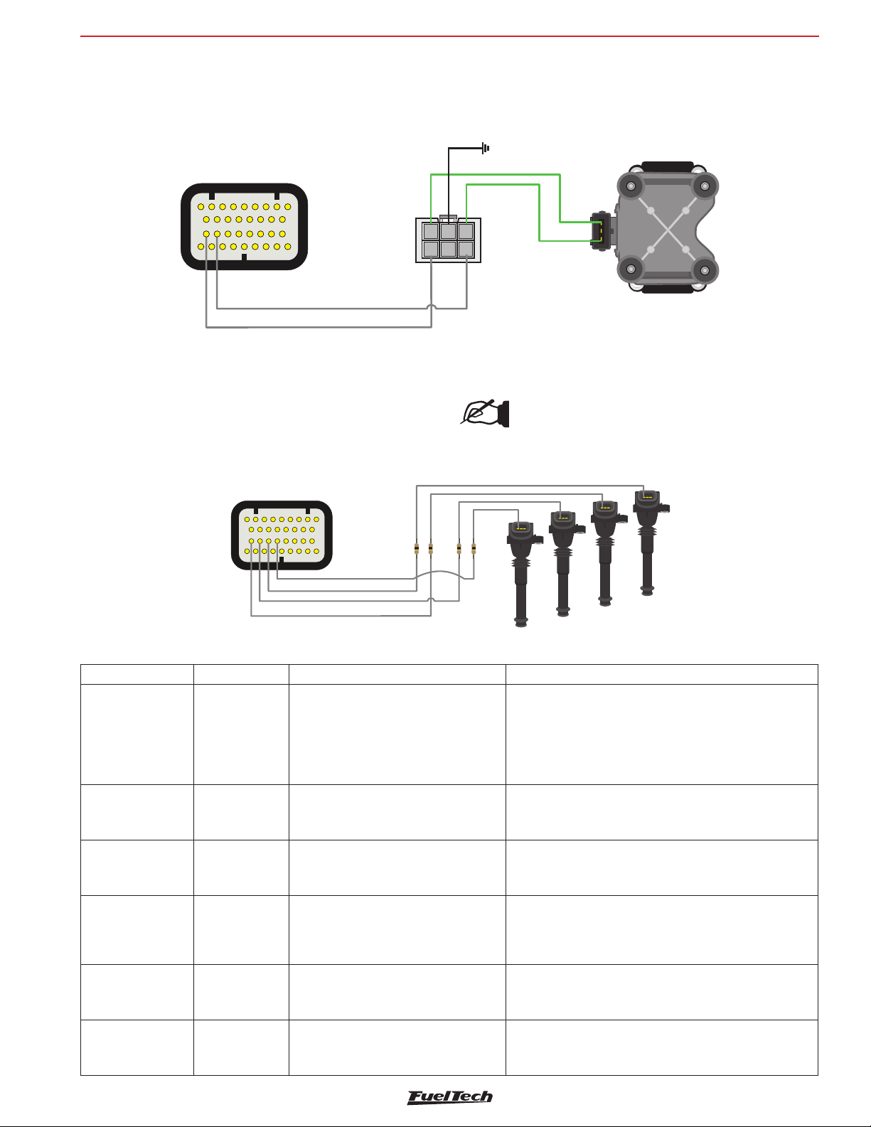
Ignition
Saída Canal 4
Saída Canal 2
Saída Canal 1
Saída Canal 3
CIL.4
CIL.2
CIL.1
CIL.3
Conector A
FT600
Wasted spark coils – electrical connections
In this case, ignition output #1 controls cylinder #1 and its twin, ignition
output #2 controls cylinder #2 and its twin, etc.
Power Ground - Engine head
Connector A
5
3
6789
4
12
10
18 19 20
2627282930 31 32 33 34
11 121314
21 22
15 16
23 24 25
17
6
3
Channel 2 Input
Channel 1 Input
Resistor Installation gray outputs
When coils with integrated ignition module are used in your vehicle
with FuelTech it’s recommended to install a 100 ohms resistor (100R)
in series with each gray output used in installation.
When using dumb coils, an external igniter must be used, such as
FuelTech SparkPRO. The FT600 ignition outputs (gray wires) will
be connected to the igniter inputs and the igniter outputs will be
connected to the coil.
Channel 1 Output
4
1
5
4
2
1
2
SparkPRO-2
Channel 2 Output
3
This procedure is used as a protection to the ECU against current
discharges in adverse situations.
NOTE:
After installing the resistor, you must insulate the area
with electrical tape or heat shrink.
Individual coils connections
Coil Type Cars where it’s usually found Pins Connection
No internal
Renault
7700875000
Bosch
0221504024
VW/Audi 20V/
BMW
Magneti Marelli
BAE700AK
Toyota
90919-02205
129700-5150
BOSCH
0221504470
0221504100
igniter
Wire in serial
association
and use a
SparkPRO-2
No internal
igniter
No internal
igniter
No internal
igniter
(Dwell:
2,50ms)
No internal
igniter
No internal
igniter
5
3
6789
4
12
10
18 19 20
2627282930 31 32 33 34
11 121314
21 22
15 16
23 24 25
17
Entrada Canal 4
Entrada Canal 3
Entrada Canal 2
Entrada Canal 1
Renault engine 2.0 16V
Fiat Punto/Linea 1.4 T-Jet
All VW/Audi 1.8 20V Turbo
BMW 328
Peugeot 306 and 405 2.0 16V
Citroen Xantia and ZX 2.0 16V
Maserati Coupé 3.2 32V
Toyota 2JZ, others
Honda CBR 1000 (1,80ms)
BMW X1/X5/M5/118/120/320
E46/E39/E38/Z3/Z4/Z8
Pin 1 bob 1: Ignition power (from SparkPRO or similar)
Pin 2 coil 2: Switched 12V from relay
Connect the pin 2 of coil 1 in the pin 1 of coil 2 (serial
association)
These coils work with 6V
Pin 1: Power ground (engine head)
Pin 2: Switched 12V from relay
Pin 3: Ignition power (from SparkPRO or similar)
Pin 1: Ignition power (from SparkPRO or similar)
Pin 2: Power ground (engine head)
Pin 3: Switched 12V from relay
Pin 1: Switched 12V from relay
Pin 2: Power ground (engine head)
Pin 3: Ignition power (from SparkPRO or similar)
Pin 1: Switched 12V from relay
Pin 2: Ignition power (from SparkPRO or similar)
Pin 1: Connected to an ignition output (gray wire)
Pin 2: Power ground (engine head)
Pin 3: Switched 12V from relay
35
Page 36

FT600
Coil Type Cars where it’s usually found Pins Connection
Integrated
ACDelco 12611424
Diamond FK0140
(Dwell 3ms)
Diamond FK0186
(Dwell 5ms)
Diamond
FK0320
Hitachi CM11-202
Hanshin MCP3350
Hanshin MCP1330
Nissan 224891F00
Hitachi AIC3103G Integrated igniter
Audi/VW
06x 905 115
Hitachi CM11-201
Bosch
022 905 100x
Denso 099700-101
Denso 099700-115
Denso 099700-061
Hitachi CM11-109
Denso 90919-022 ??
Final 27, 30, 36, 39
e 40
VW 030905110D Integrated igniter VW Gol/Voyage G6
Denso 10R 035444 Integrated igniter Toyota Camry 2.4
Bosch
0221604104
Bosch 0221604014 Integrated igniter Nissan Sentra
MSD PN 82558 No internal igniter MSD PN 82558
Bosch
0221504014
0221504460
30520-R1A-A01 Integrated igniter New Civic
Igniter (Dwell:
4,5ms)
Integrated igniter Subaru WRX
Integrated igniter
Integrated igniter
Integrated igniter
Integrated igniter VW VR6 – Golf, Passat
Integrated igniter Honda Fit
Integrated igniter Toyota/Lexus V6 3.0
Integrated igniter Captiva / Omega V6 3.6
No internal igniter
Fiat Stilo Abarth 2.4 20V (1,80ms)
Corvette LS1
Pajero 3.8 6G75 MiVec
Lancer GT, ASX, Outlander
Fiat Brava/Marea 1.8
Nissan Silvia S15
Nissan R34 (RB26DETT)
Mitsubishi Nissan 350 Z
Infiniti G35/FX35
Audi A6, S3 – VW Bora, Golf,
Passat 1.8 Turbo
Fiat Marea 2.0T, 2.4 (3,60ms)
Ignition
Pin A: Power ground (engine head)
Pin B: Reference ground (ECU reference ground)
Pin C: Connected to an ignition output (gray wire)
Pin D: Switched 12V from relay
Pin 1: Connected to an ignition output (gray wire)
Pin 2: Power ground (engine head)
Pin 3: Switched 12V from relay
Pin 1: Switched 12V from relay
Pin 2: Connected to an ignition output (gray wire)
Pin 3: Power ground (engine head)
Pin 1 - +: Switched 12V from relay
Pin 2 - B: Power ground (engine head)
Pin 3 - IB: Connected to an ignition output (gray wire)
Pin 1: Connected to an ignition output (gray wire)
Pin 2: Power ground (engine head)
Pin 3: Switched 12V from relay
Pin 1: Switched 12V from relay
Pin 2: Power ground (engine head)
Pin 3: Connected to an ignition output (gray wire)
Pin 4: Power ground (engine head)
Pin 1: Reference ground (battery negative)
Pin 2: Power ground (engine head)
Pin 3: Switched 12V from relay
Pin 4: Connected to an ignition output (gray wire)
Pin 1: Connected to an ignition output (gray wire)
Pin 2: Power ground (engine head)
Pin 3: Switched 12V from relay
Pin 1: Power ground (engine head)
Pin 2: Connected to an ignition output (gray wire)
Pin 3: Do not connect
Pin 4: Switched 12V from relay
Pin 1: Reference ground (battery negative)
Pin 2: Connected to an ignition output (gray wire)
Pin 3: Power ground (engine head)
Pin 4: Switched 12V from relay
Pin 1: Switched 12V from relay
Pin 2: Reference ground (battery negative)
Pin 3: Connected to an ignition output (gray wire)
Pin 4: Power ground (engine head)
Pin A: Power ground (engine head)
Pin B: Reference ground (battery negative)
Pin C: Connected to an ignition output (gray wire
Pin D: Switched 12V from relay
Pin 1: Connected to an ignition output (gray wire
Pin 2: Ground
Pin 3: Switched 12V from relay
Pin 1: Ignition power (from SparkPRO or similar)
Pin 2: Do not connect
Pin 3: Switched 12V from relay
Pin 1: Ignition power (from SparkPRO or similar)
Pin 2: Power ground (engine head)
Pin 3: Switched 12V from relay
Pin 1: Switched 12V from relay
Pin 2: Reference ground (battery negative)
Pin 3: Ignition power (from SparkPRO or similar)
36
Page 37

Ignition
Wasted spark coils connections
Coil Type Cars where it’s usually found Pin Connection
No integrated
Bosch
F000Z S0103
Bosch 4 cylinders
(3 wires)
F 000 Z S0 213
F 000 Z S0 222
0 221 503 011
Bosch 4 cylinders
(3 wires)
F 000 ZS0 203
F 000 ZS0 205
47905104
19005212
1208307
(6 wires – 4
channels)
Bosch 6 cylinders
0 221 503 008
Delphi 4 cylinders
(round)
Bosch
F000Z S0103
Bosch 4 cylinders
(3 wires)
F 000 Z S0 213
F 000 Z S0 222
0 221 503 011
Bosch 4 cylinders
(3 wires)
F 000 ZS0 203
F 000 ZS0 205
47905104
19005212
1208307
(6 wires – 4
channels)
Bosch 6 cylinders
0 221 503 008
igniter (two
spark plug
outputs)
No integrated
igniter
No integrated
igniter
No integrated
igniter
Individual
cylinder
triggering
No integrated
igniter
Integrated
igniter
No integrated
igniter (two
spark plug
outputs)
No integrated
igniter
No integrated
igniter
No integrated
igniter
Individual
cylinder
triggering
No integrated
igniter
Fiat Palio, Siena, Uno 1.0 , 1.5, 1 .6,
Tempra 2 .0
Celta, Corsa, Gol Flex, Meriva,
Montana Vectra 16V
Fiat Linea 1.9 16V
Astra, Kadett, Ipanema, Vectra 8V, Zafira
Fiat Stilo 1.8 16V
GM Meriva 1.8 16V
GM Zafira 1.8 and 2.0 16V
GM Omega 4.1, Ford V6
GM Corsa MPFI (of 98 to 2002)
Fiat Palio, Siena, Uno 1.0 , 1.5, 1 .6,
Tempra 2 .0
Celta, Corsa, Gol Flex, Meriva,
Montana
Vectra 16V
Fiat Linea 1.9 16V
Astra, Kadett, Ipanema, Vectra 8V, Zafira
Fiat Stilo 1.8 16V
GM Meriva 1.8 16V
GM Zafira 1.8 and 2.0 16V
GM Omega 4.1, Ford V6
FT600
Pin 1: Ignition power (from SparkPRO or similar)
Pin 2: Switched 12V from relay
Pin 1a (A): Ignition power (from SparkPRO or similar)
Pin 15 (B): Switched 12V from relay
Pin 1b (C): Ignition power (from SparkPRO or similar)
Pin 1: Ignition power (from SparkPRO or similar)
Pin 2: Switched 12V from relay
Pin 3: Ignition power (from SparkPRO or similar)
Pin A – cyl. 3: Ignition power (from SparkPRO or similar)
Pin B – cyl. 2: Ignition power (from SparkPRO or similar)
Pin C – cyl. 1: Ignition power (from SparkPRO or similar)
Pin D – cyl. 4: Ignition power (from SparkPRO or similar)
Pin E: Power ground (engine head)
Pin F: Switched 12V from relay
Pin 1: Ignition power (from SparkPRO or similar)
Pin 2: Ignition power (from SparkPRO or similar)
Pin 3: Ignition power (from SparkPRO or similar)
Pin 4: Switched 12V from relay
Pin A: Gray #2 (cylinders 2 and 3)
Pin B: Gray #1 (cylinders 1 and 4)
Pin C: Power ground (engine head)
Pin D: Switched 12V from relay
Pin 1: Ignition power (from SparkPRO or similar)
Pin 2: Switched 12V from relay
Pin 1a (A): Ignition power (from SparkPRO or similar)
Pin 15 (B): Switched 12V from relay
Pin 1b (C): Ignition power (from SparkPRO or similar)
Pin 1: Ignition power (from SparkPRO or similar)
Pin 2: Switched 12V from relay
Pin 3: Ignition power (from SparkPRO or similar)
Pin A – cyl. 3: Ignition power (from SparkPRO or similar)
Pin B – cyl. 2: Ignition power (from SparkPRO or similar)
Pin C – cyl. 1: Ignition power (from SparkPRO or similar)
Pin D – cyl. 4: Ignition power (from SparkPRO or similar)
Pin E: Power ground (engine head)
Pin F: Switched 12V from relay
Pin 1: Ignition power (from SparkPRO or similar)
Pin 2: Ignition power (from SparkPRO or similar)
Pin 3: Ignition power (from SparkPRO or similar)
Pin 4: Switched 12V from relay
37
Page 38

FT600
Coil Type Cars where it’s usually found Pin Connection
Delphi 4 cylinders
(round)
Delphi 4 cylinders
(square)
Sagem
96358648
Bosch 4 Cylinders
(4 wires)
032 905 106 B/D
F000ZS0210
Eldor – 4 Cylinders
(6 wires – 4
channels)
06A 905 097
06A 905 104
VW V6
078 905 104
GM Coil
94702536
DELPHI CE20131
Pantera coil
BMW
Integrated
igniter
Integrated
igniter
No integrated
igniter
Integrated
igniter
Integrated
igniter
Individual
cylinder
triggering
Integrated
igniter
Integrated
igniter
Integrated
igniter
No integrated
igniter
GM Corsa MPFI (of 98 to 2002)
GM Corsa MPFI (of 98 to 2002)
Peugeot 1.4
VW Golf, Bora, Audi A3 and A4,
Seat Ibiza and Córdoba
Bora, New Beetle, Polo
Audi A4 2.8 V6
Audi A6
Passat 2.8 V6
GM Agile 1.4
-
318ti compact 94/00
Ignition
Pin A: Gray #2 (cylinders 2 and 3)
Pin B: Gray #1 (cylinders 1 and 4)
Pin C: Power ground (engine head)
Pin D: Switched 12V from relay
Pin 1: Switched 12V from relay
Pin 2: Power ground (engine head)
Pin 3: Gray #1 (cylinders 1 and 4)
Pin 4: Gray #2 (cylinders 2 and 3
Pin 1: Gray #1 (cylinders 1 and 4)
Pin 2: Gray #2 (cylinders 2 and 3)
Pin 3: Power ground (engine head)
Pin 4: Switched 12V from relay
Pin 1: Gray #1 (cylinders 1 and 4)
Pin 2: Switched 12V from relay
Pin 3: Gray #2 (cylinders 2 and 3)
Pin 4: Power ground (engine head)
Pin 1: Power ground (engine head)
Pin 2: Gray - C (cylinder 4)
Pin 3: Gray - B (cylinder 3)
Pin 4: Gray - D (cylinder 2)
Pin 5: Gray - A (cylinder 1)
Pin 6: Switched 12V from relay
Pin 1: Power ground (engine head)
Pin 2: Gray #1 (cylinders 1 and 4)
Pin 3: Gray #2 (cylinders 2 and 5)
Pin 4: Gray #3 (cylinders 3 and 6)
Pin 5: Switched 12V from relay
Pin A: Gray #2 (cylinders 2 and 3)
Pin B: Gray #1 (cylinders 1 and 4)
Pin C: Reference ground (battery negative)
Pin D: Power ground (engine head)
Pin E: Switched 12V from relay
Pin A: Gray #1
Pin B: Reference ground (battery negative)
Pin C: Power ground (engine block)
Pin D: Power ground (engine head)
Pin E: Switched 12V from relay
Pin 1: cylinder 4 - Sparkpro
Pin 2: Switched 12V from relay
Pin 3: Power ground (engine block)
Pin 4: Not used
Pin 5: Cylinder 1 - Sparkpro
Pin 6: Cylinder 3 - Sparkpro
Pin 7: Cylinder 2 - Sparkpro
38
Page 39
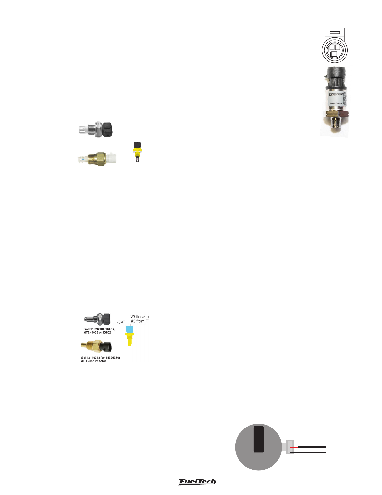
Delco 213-190AC
VW Hall Effect distributor connections
Sensors and actuators
FT600
12. Sensors and actuators
FT600 has some pre-defined sensors available as standard, but, it’s
possible to setup any kind of analog sensor on its inputs or even
to connect it and read a sensor in parallel with the OEM ECU. This
configuration is done on the custom mode through software FTManager
and USB cable on a PC.
12.1 Intake air temperature sensor
With this sensor, the ECU can monitor the intake air temperature and
perform real time compensations.
White wire
Fiat Nº 75.479.76,
MTE-5053 ou 901IG
GM N°25036751
# from7FT
Models:
• Fiat: Delphi / NTK (3,3kΩ a 20ºC);
• GM (American): ACDelco: 213-190 / GM n°25036751.
One of its pins is connected to the battery negative. The other to the
white #7 wire (standard – can be changed).
7777
-BAT
FuelTech PS-150/300/1500 sensor below:
- Connection: 1/8” - 27NPT
- Pressure Range: 0 to 150/300/1500psi
- Power Voltage: 5V
AB
C
- Output Scale: 0.5-4.5V
- Electric Connector: 3-way Metri Pack 150
Pin A: Battery’s Negative
Pin B: 5V supply
Pin C: Output signal
FuelTech part numbers:
5005100020 - 0-150 psi sensor
5005100021 - 0-300 psi sensor
5005100022 - 0-1500 psi sensor
As FT600 is fully configurable, practically any automotive pressure
sensor can be used – if the voltage x pressure table is known, you
can setup through FTManager software.
12.4 Throttle position sensor (TPS)
This sensor is a potentiometer installed on the throttle to inform the ECU
about its position. If needed, it is possible to run the engine without
this sensor, but, it is very important for a fine tuning. When possible,
use the OEM TPS. This ECU is calibrate to any kind 0-5V TPS sensor.
Anyway, FuelTech products are compatible with any 0-5V TPS sensor,
since they have calibration function.
12.2 Engine temperature sensor
This sensor is very important for a good running engine, as varying
engine temperatures dramatically affect an engine’s fuel and timing
requirements.
On water cooled engines, place this sensor near the engine head,
reading the water temperature. On air cooled engines, install this
sensor reading the engine oil temperature.
Models:
• Fiat: Delphi / NTK (3,3kΩ a 20ºC);
• GM (American): ACDelco: 213-928 / GM: 12146312 (or
15326386).
One of its pins is connected to the battery negative. The other to the
white #5 wire (standard – can be changed).
Discovering the TPS pinout
With a multimeter in the range of 20k Ohms, disconnect the from
the FuelTech ECU and let the ignition key off. Check the resistance
between the Green/Red (5V supply) and Black (battery’s negative)
wires. Resistance should not vary when accelerating. If vary, reverse
the wires so that the resistance of the TPS varies only between the
White wire #11 (default TPS input signal) and Green/Red and between
White #11 and Black wires.
The TPS signal voltage should vary according to throttle opening,
with gap bigger then 3V between fully closed and wide open throttle.
12.5 Crank trigger/RPM sensor
To control fuel and ignition, this ECU is able to read magnetic and
Hall Effect sensors.
Distributor
To read RPM signal from a Hall Effect distributor, it should have a sensor
with at least 3 pin and have the same number of reading windows (or
“triggers”) than the engine has number of cylinders.
12.3 Fuel and oil pressure
FuelTech PS-150/300/1500 is a high precision sensor responsible for
general pressure readings (fuel, oil, boost, exhaust back pressure, etc.)
It can be purchased online at www.fueltech.net or from an authorized
FuelTech dealer (check the website to locate the dealer nearest to you).
+
-
12V Switched
RPM - red
Negative’s Battery
39
Page 40
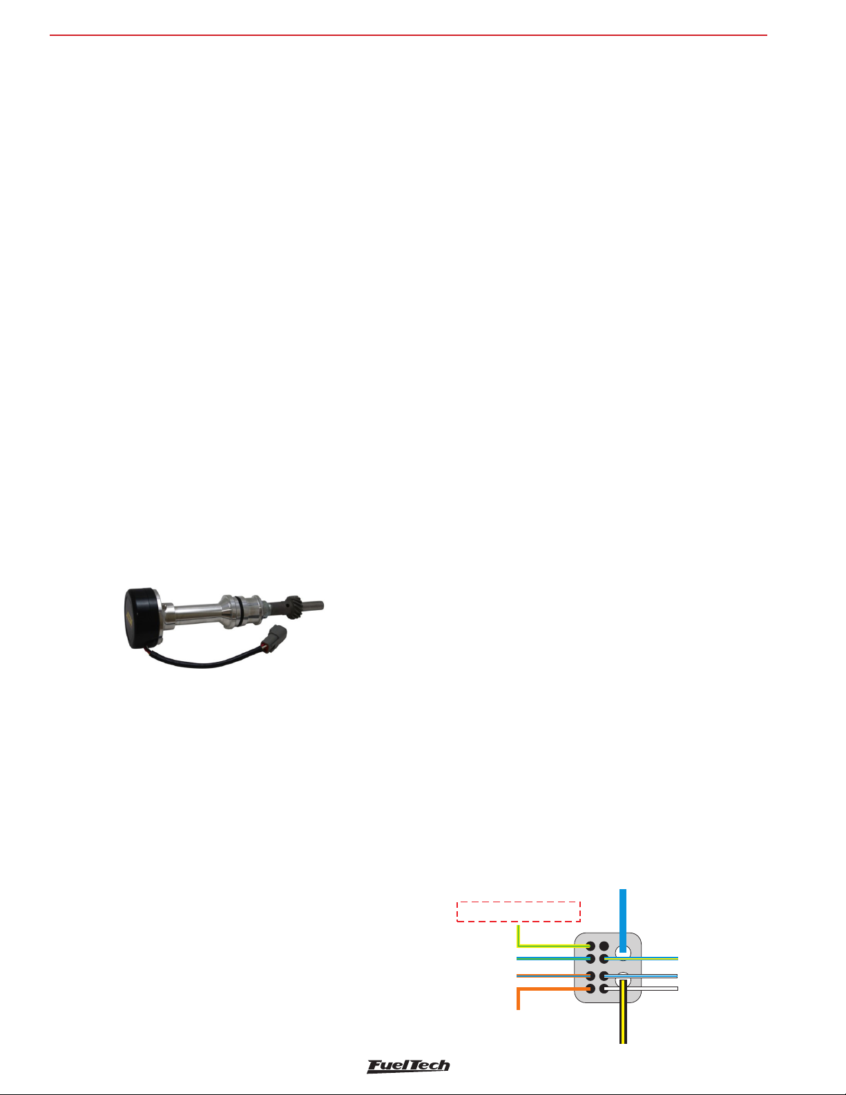
FT600
92/95
Ignition signal input: Connect to Gray #1
With external coil, do not connect
12V input
Do not connect
Do not connect
Do not connect
Do not Connect
Do not connect
Reference - 2 (crank) 4 (cam):
Connect white wire from black shielded cable
Si nal 2 () 4 ():g-crank cam
Connect red wire from black shielded cable
Sensors and actuators
Crank trigger
The crankshaft trigger wheel is responsible for informing the exact
position of the crankshaft to the electronic ignition management
system, in such a way that this system is able to determine the ignition
timing in the engine. The trigger wheel is installed on the crankshaft,
outside or inside the engine block, with a specific alignment. Usually,
the Crankshaft Trigger Wheels placed on the outside of the block are
put in front of the engine, by the front crankshaft pulley, or in the rear
of the engine, by the flywheel. There are many types of Trigger Wheels,
but the compatible ones are mentioned below
60-2: this is, in general, the most used type of trigger wheel. It is a
wheel with 58 teeth and a gap (fault point) equivalent to two missing
teeth, therefore called “60-2”. This trigger wheel is found in most
Chevrolet (Corsa, Vectra, Omega, etc.), VW (Golf, AP TotalFlex, etc.),
Fiat (Marea, Uno, Palio, etc.), Audi (A3, A4, etc.) and Renault (Clio,
Scènic, etc.) Models, among other car makers. Ford Flex models with
Marelli ECU use this type of trigger wheel also.
36-2: standard in Toyota engines, being 34 teeth and a gap equivalent
to two missing teeth.
36-1: 35 teeth and a gap equivalent to one missing tooth. It can be
found in all Ford vehicle lines, with 4 or 6 cylinders (except the Flex
models with Marelli injection, which use the 60-2 trigger wheel).
12 teeth: this type is used by AEM’s Engine Position Module (EPM)
distributor. In this case, the cam sensor from the EPM must be used.
This distributor has 24 teeth, but as it rotates half-way for each full
engine RPM, there will only be 12 teeth per RPM. Setup the Ignition with
12 teeth at crank (24 at cam) and the 1st tooth alignment with 60°.
• Pin 2 – yellow – CRANK signal: connect to red wire from FT600
black shielded cable (pin 17)
• Pin 3 – red – sensor feed: connect to a switched +12V
• Pin 4 – black – sensor ground: connect directly to battery’s
negative.
FT600 setup: RPM signal “2 (crank) or 4 (cam)” (4G63) or “3
(crank) or 6 (cam)” (6G72), Hall Effect crank and cam sensors, rising
edge on both. Wasted spark ignition. 1st tooth alignment: 67
Mitsubishi 2G CAS: uses the same settings that 1G CAS, but has a
sensor on the crankshaft (reading a 2 tooth trigger) and a cam sync
sensor.
Crank trigger sensor:
• Pin 1: switched 12V
• Pin 2: CRANK signal: connect to red wire from FT600 Black
shielded cable (pin 17)
• Pin 3: connect directly to battery’s negative
Cam sync sensor:
• Pin 1: switched 12V
• Pin 2: CAM signal: connect to white wire from FT600 gray
shielded cable (pin 15)
• Pin 3: connect directly to battery’s negative
Ignition settings:
• Stock Honda coil and igniter: setup ignition as “Distributor –
single coil” and select option “Rising edge (Honda distributor)”.
In this option, only the ignition output #1 will be active.
AEM EPM Module
• Red: Switched12V;
• Black: Battery negative;
• Yellow: red wire from the black shielded cable, white wire must
be left disconnected. Setup it as Hall Effect RPM sensor, falling
edge;
• White: white wire from the gray shielded cable. Setup it as Hall
Effect CAM sensor – falling edge.
Setup ECU as 12 teeth (at crank) 24 (at cam) and use 60° for 1st
tooth alignment.
Mitsubishi 1G CAS: due to the fact the CAM signal has two slots on
this CAS, it’s only possible to control the ignition on wasted spark mode
and the fuel injection on multipoint or semi-sequential. No sequential
fuel or ignition will work on this CAS with 2 slots on the CAM.
• Pin 1 – white – CAM signal: connect to white wire from FT600
gray shielded cable (pin 15)
40
• Multi coils and/or external igniter: in this case, ignition can be
controlled in wasted spark or sequential modes. Ignition output
must be setup as “Honda distributor”, but as Falling edge or
Rising edge, according to the external igniter used.
• 1, 2, 3, 4, 5, 8, 10 and 24 teeth: options available according
to the number of engine cylinders. When having these trigger
wheels, the use of a camshaft position sensor is mandatory,
in order to maintain the synchronization of the parts. Also, the
teeth must be equidistant. They can be found in models such as
Subaru, Mitsubishi Lancer and 3000GT, GM S10 Vortec V6, etc.
Honda Distributor
Page 41
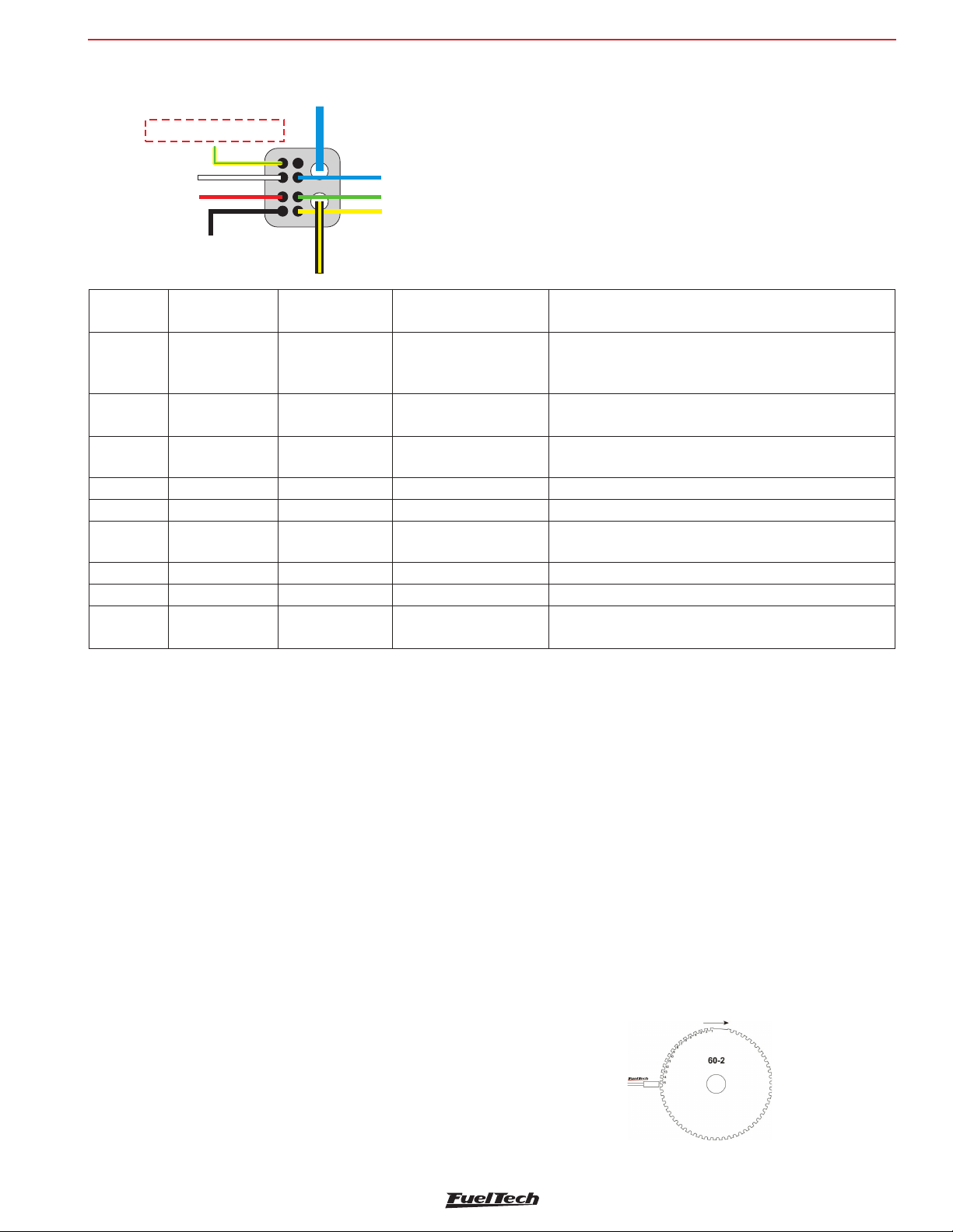
96/00
Ignition signal input: Connect to Gray #1
With external coil, do not connect
Do not connect
Do not Connect
Reference - 2 (crank) 4 (cam):
Connect white wire from black shielded cable
Do not connect
Do not connect
Si nal 2 () 4 ():g-crank cam
Connect red wire from black shielded cable
12V input
Do not connect
Sensors and actuators
FT600
Distributor
Pin
Honda 92/95
(wire color)
Honda 96/00
(wire color)
FT600 connection Configuration
With OEM coil and
1 Yellow/green Yellow/green
igniter, connect gray #1
wire
2 Blue/Green White Do not connect
3 Orange/Blue Red
4 Orange
Black Do not connect
Connect white wire from
black shielded cable
5 Blue/Yellow Blue Do not connect
6 White/Blue Green
Connect red wire from
black shielded cable
7 White Yellow Do not connect
8 Blue Blue Do not connect
9 Black/Yellow Black/Yellow 12V input
MSD distributor and crank trigger:
The distributors are equipped with VR/magnetic sensors e must be
wired as the following:
With stock Honda coil and igniter: connect to gray wire
#1 and setup as “Honda Distributor”.
With multi-coils, and external igniter: do not connect
Reference - 2 (crank) 4 (cam)
Signal - 2 (crank) 4 (cam)
12V input for OEM coil and igniter (inside the distributor)
With external coil, do not connect
Cam sync sensor:
Not utilized, unless you are running crank trigger and distributor
(or a dedicated cam sync sensor) with a single tooth.
• Orange/black: connected to the red wire of black shielded cable
• Purple/black: connected to the white wire of black shielded cable
Any mechanical or centrifugal advance must be locked. The crank
trigger kits have different wire colors and the wiring must be as
following:
• Purple: connected to the red wire of black shielded cable of
• Green: connected to the white wire of black shielded cable of
The RPM signal settings must be:
• 4 cylinders: 2 (at crank) or 4 (at cam);
• 6 cylinders: 3 (at crank) or 6 (at cam);
• 8 cylinders: 4 (at crank) or 8 (at cam);
RPM sensor:
VR differential, rising edge, crank index position 45º (need to calibrate
ignition with timing light)
of FT600
of FT600
FT600;
FT600
48-2, 30-2, 30-1, 24-2, 24-1, 15-2, 12-3, 12-2, 12-1, 12+1
and 4+1 teeth: These are less common types, but they are perfectly
compatible. These trigger wheels can operate without a camshaft
position sensor, as they have a gap that indicates the TDC on cylinder 1.
In order to correctly inform the engine position to the injection module,
it is necessary that the injection has the right information about the
alignment of the trigger wheel in relation to the TDC on cylinder 1.
The image below shows a 60-2 trigger wheel with the sensor aligned
on the 15th tooth after gap. In this image, for example, the engine
is on the TDC on cylinder 1. Notice that the RPM is clockwise, and
therefore, the TDC on cylinder 1 is set 15 teeth after the sensor passes
the gap. That is exactly the number of teeth that must be informed to
the injection upon its configuration.
60-2 Trigger Wheel Aligned on the 15th tooth after the gap
41
Page 42
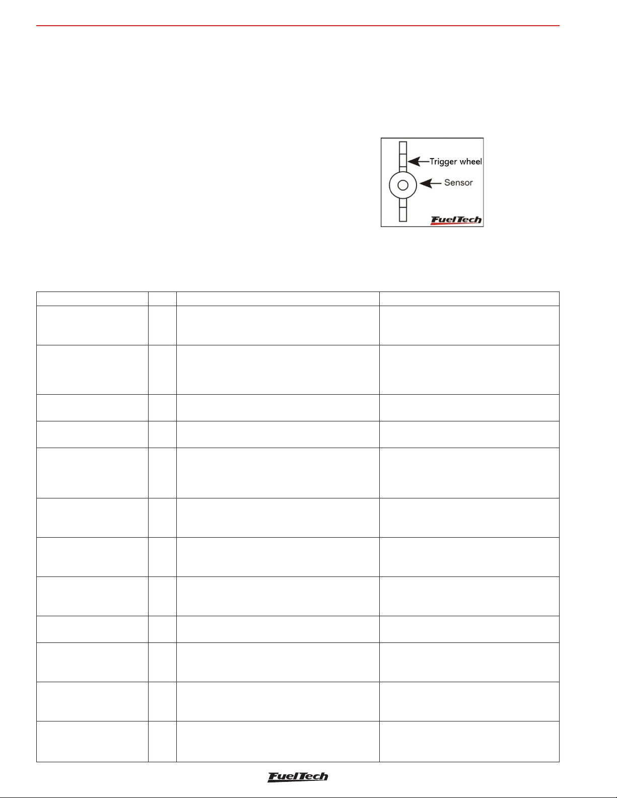
FT600
Sensors and actuators
Of the space in between them. The minimum diameter for the
fabrication of a 60-2 trigger wheel is 125mm (5”).
For 36-1 trigger wheels, the minimum diameter recommended is
100mm (4”). Trigger wheels with smaller diameters can be fabricated,
but reading errors may occur and the engine may not work.
Crankshaft trigger sensor
When controlling the ignition with a trigger wheel, it is necessary to
have a sensor that reads the signal from its teeth and informs the
engine position to the injection. There are two types of crankshaft
trigger sensors:
VR sensor: this is the type that is most commonly used in cars
nowadays, especially with 60-2 and 36-1 trigger wheels. One of
its main characteristics is that it does not receive 12V or 5V; it only
Crank trigger sensors table
Sensor Type Cars where it’s usually found Pin connection
Chevrolet Corsa 8V MPFI, Omega 2.2, 4.1 and 2.0
Bosch 3 wires VR
Bosch 3 wires VR
Ford 2 wires
Fiat 2 wires
Siemens 2 wires VR Renault Clio, Scènic
Magneti Marelli
(P/N Fiat 464.457.31)
(P/N Marelli
4820171010)
Delphi 3 wires (3 teeth
wheel)
Fiat engine E-TorQ 1.8 16V Hall
VW TotalFlex/Gol Gti
Hyundai Tucson 2.0 16V
Denso (Suzuki Bickes) VR Suzuki Hayabusa e Suzuki SRAD
Mitsubishi 1.6 16V (2
teeth)
VW/Audi 20V3 wires
Bosch – 0261210148
Denso 3 wires Hall Honda Civic Si
(alcohol), S10 2.2,Silverado, Astra, Kadett MPFI, Vectra,
Calibra, VW Golf, Passat, Alfa 164 3.0
Chevrolet Omega 2.0 Gasolina and 3.0, Corsa 16V/
GSi, Tigra, Fiat Marea 5 Cilindros, Citroën ZX 2.0,
Xantia 2.0, Peugeot 306 2.0 16V, Peugeot 405MI
Fiat Linea 1.9 16V
VR
VR Fiat Palio, Uno, Strada, Siena 1.0 – 1.5 8V MPI
Hall GM S10 4.3 V6
Hall
Hall Mitsubishi Colt e Lancer
VR
VW Golf 1.8 20V/Golf 1.6, 2.0/Bora 2.0– EA111
Ford Zetec, Ranger V6
Fiat Punto/Fiat 500 1.4 Turbo
Fiat engine E-TorQ
1.8 16V
all VW AP TotalFlex
Hyundai Tucson 2.0 16V
Audi A3 1.8 20V
generates an electromagnetic signal based on induction. It might have
2 or 3 wires (the third wire is an electromagnetic shield).
Hall Effect sensor: it is usually found on 2, 3 and 4-tooth trigger
wheels and some 36-1 and 60-2 types. It receives a 5V or 12V
feed and emits a square wave signal. It invariably has 3 pins: voltage,
negative and signal.
The crank Wheel should be aligned with the sensor
Pin 1: red wire (black shielded cable)
Pin 2: white wire (black shielded cable)
Pin 3: shield (black shielded cable)’
Pin 1: white wire (black shielded cable)
Pin 2: red wire (black shielded cable)
Pin 3: shield (black shielded cable)
Pin 1: red wire (black shielded cable)
Pin 2: white wire (black shielded cable)
Pin A: red wire (black shielded cable)
Pin B: white wire (black shielded cable)
Pin +: red wire (black shielded cable)
Pin – : white wire (black shielded cable)
Pin S : shield (black shielded cable)
Pin A: 5V (FT green/red wire)
Pin B: battery negative
Pin C: red wire (black shielded cable)
Pin 1: battery negative
Pin 2: red wire (black shielded cable)
Pin 3: 5V (FT green/red wire)
Pin 1: 5V (FT green/red wire)
Pin 2: red wire (black shielded cable)
Pin 3: battery negative
Pin 1: red wire (black shielded cable)
Pin 2: white wire (black shielded cable)
Pin 1 - black: battery negative
Pin 2 - brown: red wire (black shielded cable)
Pin 3 - red: 5V (FT green/red wire)
Pin 1: shield (black shielded cable)
Pin 2: white wire (black shielded cable)
Pin 3: red wire (black shielded cable)
Pin 1: 5V (FT green/red wire)
Pin 2: shield (black shielded cable)
Pin 3: red wire (black shielded cable)
42
Page 43
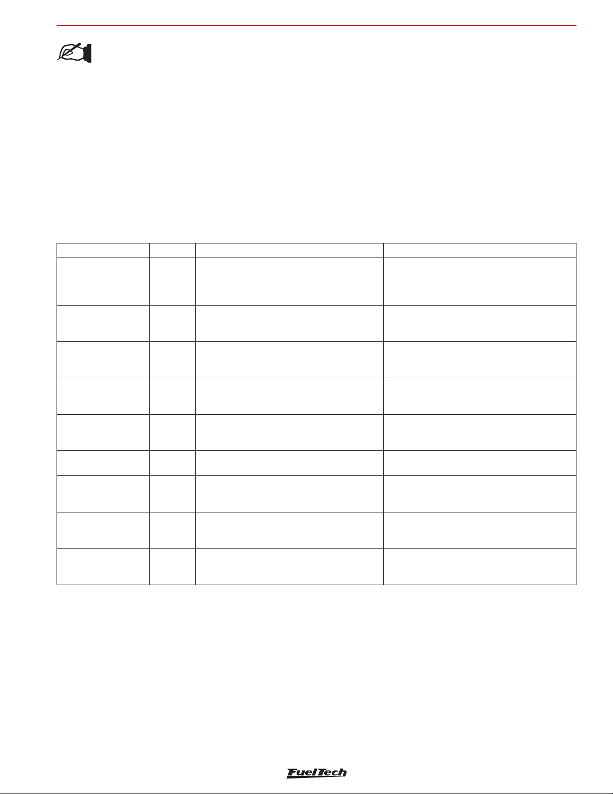
Sensors and actuators
FT600
NOTE:
If a VR sensor doesn’t pick up RPM signal, try to swap
the sensor wires (red and white wires)
A very simple test using a tester can identify if a Crankshaft Trigger
Sensor is an inductive or a Hall Effect sensor. Turn the tester on the
resistance measurement mode at a 2000Ω scale and connect its
probes to the sensor’s pins. Test pin 1 with the other two. If a resistance
of 600-1200Ω is found, the sensor tested is of inductive type.
If no resistance is found among any of the pins, or if the resistance
found is much higher than 1200Ω, it is either a Hall Effect sensor,
or an inductive sensor with a broken coil. Notice that, when finding
Cam sync sensors table
Sensor Type Cars where it’s usually found Pin connection
Chevrolet Astra 16V, Calibra, Vectra, Ômega 4.1,
Bosch 3 wires Hall
Bosch 3 wires Hall
Bosch 3 wires Hall Chevrolet Corsa 16V, Tigra
Delphi Cam sensor Hall GM S10 4.3 V6
Bosch 3 wires VR Alfa 164 6 cylinders
Ford 2 wires
Denso (Suzuki Bikes)
3 wires (close the small
hole with an adhesive)
Denso 3 wires Hall Honda Civic Si
BMW 550582A Hall BMW 325i, 325is, 525i M3 (1992 a 1995)
VR
Optical Mitsubishi 1.6 16V
Zafira 6V, Citroën ZX 2.0, Xantia, Peugeot 306 2.0
16V, 05MI, Hyundai Tucson 2.0 6V, Fiat Marea 5
Cylinders all VW/Audi 1.8 20V
Chevrolet Vectra 16V (97 and on)
Fiat Punto T-Jet, Fiat 500 Fiat E-TorQ1.8 16V e 1.4
Turbo
Ford Zetec, Ranger V6 Suzuki Hayabusa e Suzuki
SRAD
the resistance between pins 2 and 3, for example, pin 1 must be
connected to the battery’s negative terminal and the other 2 to FT
shielded cable. If the module does not capture the signal, invert the
white and red wires connections.
12.6 Camshaft position sensor
This sensor tells the ECU when the cylinder #1 is reaching its TDC on
the compression stroke. With this information it is possible to control
ignition and fuel injection in sequential mode.
Installation and alignment of this sensor are pretty simple. The only
requirement is that this sensor is triggered before the crank trigger
sensor goes through the gap on the crank trigger wheel.
Pin 1: 5V (FT green/red wire)
Pin 2: white wire (gray shielded cable)
Pin 3: shield (gray shielded cable)
Pin 1: shield (gray shielded cable)
Pin 2: white wire (gray shielded cable)
Pin 3: 5V (FT green/red wire)
Pin 15: 5V (FT green/red wire)
Pin 6: white wire (gray shielded cable)
Pin 17: shield (gray shielded cable)
Pin A: shield (gray shielded cable)
Pin B: white wire (gray shielded cable)
Pin C: 5V (FT green/red wire)
Pin 1: shield (gray shielded cable)
Pin 2: white wire (gray shielded cable)
Pin 3: shield (gray shielded cable)
Pin 1: white wire (gray shielded cable)
Pin 2: shield (gray shielded cable)
Pin 1 - black: shield (gray shielded cable)
Pin 2 - white/red: white wire (gray shielded cable)
Pin 3 - red: 5V (FT green/red wire)
Pin 1: 5V (FT green/red wire)
Pin 2: shield (gray shielded cable)
Pin 3: white wire (gray shielded cable)
Pin 1: 5V (FT green/red wire)
Pin 2: white wire (gray shielded cable)
Pin 3: shield (gray shielded cable)
12.7 O2 sensor
Wideband O2 sensor
The use of wideband lambda sensors on FT600’s input requires an external conditioner (WB-O2 Slim or WB-O2 Datalogger). It is important
to verify the measurement range of conditioner analog output, as this will be informed during the configuration of FT600’s O2 input (0,651,30, 0,65-4,00 or 0,65 to 9,99)
Narrowband O2 sensors
Although less precise than the wideband lambda sensor, narrowband O2 sensors can be connected to the ECU input for the display of values
(in Volts) at the Dashboard and at the Diagnostic Panel. Narrowband O2 sensors usually follow a standard set of colors, facilitating the wiring.
The table below shows the wiring instructions based on the color scheme generally used for O2 sensor wires:
43
Page 44
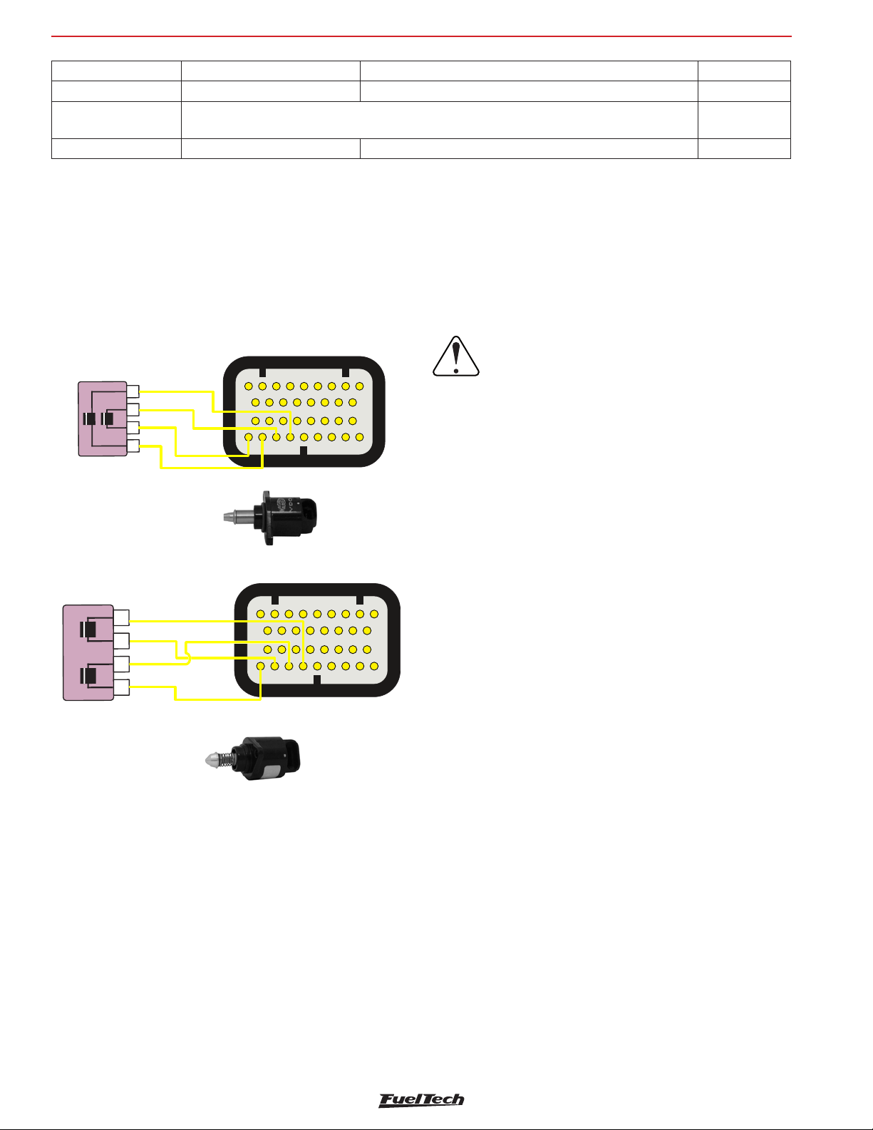
FT600
Connector A
Pin 4: 4Yellow
Yellow output1
Yellow output2
Yellow output3
Yellow 4 output
Pin 4: 4Yellow
Connector A
Yellow output3
Yellow output4
Sensors and actuators
wire Color 4-wire O2 sensor 3-wire O2 sensor 1-wire
Black Signal Output Signal Output Signal
White (2 wires)
Switched 12V and ground (connect one wire onto the 12V and the other to ground – there is
no polarity)
Not featured
Gray Battery’s negative terminal Not featured Not featured
As a general rule, if there are two wires with the same color, one is the switched 12V and the other is the ground. After connecting the O2
sensor to the ECU, the O2 sensor input must be set up as guides chapter 15.5.
12.8 Step motor – idle speed
Its control is done through the four yellow outputs of the connector A, also used for electronic throttle control. After selecting the idle speed
control as step motor the four yellow outputs are automatically set up as “step motor” on the harness connection table. Below are some known
step motor connections.
VW stepper motor - Magneti Marelli
4
3
2
1
Engines VW: Magneti Marelli
Nº: 40430102 / 40439102
Pin 1: 2Yellow
Pin 2: 1Yellow
Pin 3: 3Yellow
Yellow 1 output
Yellow 2 output
12
10
11 121314
18 19 20
2627282930 31 32 33 34
GM stepper motor - Delphi
4
3
2
1
GM : Chevrolet / DelphiEngines
N°: 17108187 / ICD00124
Pin 1: 1Yellow
Pin 2: 3Yellow
Pin 3: 2Yellow
12
10
18 19 20
2627282930 31 32 33 34
5
3
4
21 22
3
4
11 121314
6789
15 16
23 24 25
5
6789
15 16
23 24 25
21 22
IMPORTANT NOTE:
Step motor is calibrated every time the ECU is
turned on, so, before cranking the engine, it is
17
recommended to wait about 2s after turning
the ignition switch on. If this procedure is
not respected, the engine may be revved up
unwittingly during the step motor calibration,
coming back to normal within seconds.
If your step motor is different from the ones listed here, do what follows:
1. Put a tester on the 200 Ohms range;
2. Measure the step motor actuators until you find a resistance of
approximately 50 Ohms. That’s one pair of coils;
3. Connect yellow #1 and yellow #3 to a pair of coils and yellow
#2 and yellow #4 to the other pair.;
17
4. If the step motor remains fully opened after the calibration, change
yellow #1 by yellow #3 position.
FT600 step motor control is compatible with the great majority of
actuators nowadays.
Usually, with this simple test you’re able to make the step motor work
normally.
44
Page 45
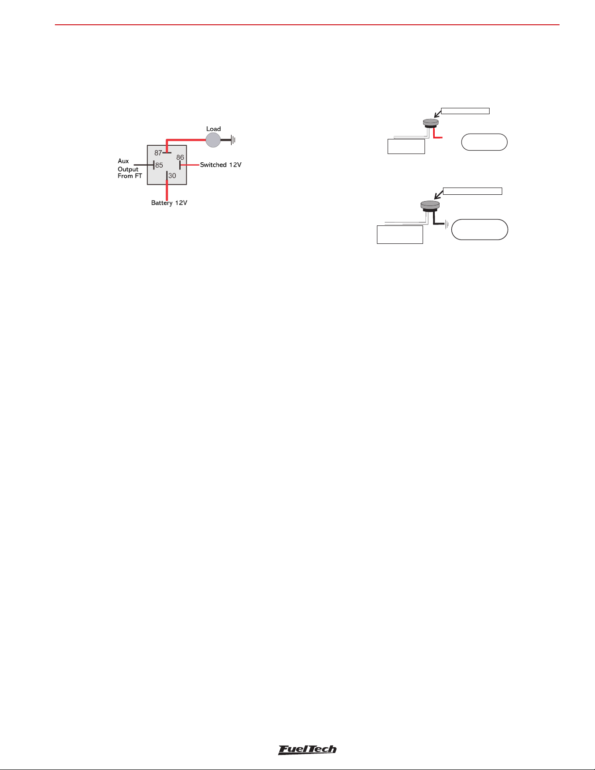
A/C button positive when ON
ON
Auxiliary outputs
FT600
13. Auxiliary outputs
The installation of a fuse equivalent to the charge is recommended. The
auxiliary outputs have an overload protection system, with automatic
current cut-off. They trigger the charges (lamps, relays, etc.) with a
negative signal. Thus, the positive terminal must be connected to a
switched 12V.
The auxiliary outputs must be set manually according to the desired
function in the outputs (blue, gray or yellow wires) that are not being
used as injector or ignition outputs.
In case of having back current and keeping relays switched on with
ECU powered off, use a 1N4004 diode.
Each output must be configured in accordance to its function.
For more information about the outputs programming, see chapter 19.
13.1 Cooling fan 1 and 2
This output is responsible for switching an electric fan according to
the module’s settings. The relay used must be adequate to the electric
fan’s current (50A, for example). The relay is switched by negative
(sourced by the output), and the positive a switched 12V.
A/C button
In order to have the air conditioning control, the A/C button on the
dashboard must be connected to a white input of FT600. The two
connection options are:
A/C button on the dash
+12V
When A/C is turned
White wire
A/C signal input
, white wire receivesON
positive
A/C button negative when
A/C button on the dash
When A/C is turned
White wire
A/C button input
, white wire receivesON
negative
The air conditioning will remain turned on as long as the A/C Signal
Input receives signal from the button. The signal polarity can be chosen
and it varies depending on the installation.
A/C Compressor
A/C compressor must be controlled with a relay, triggered by an
auxiliary output (sends negative when activated).
The auxiliary output that was setup as A/C will activate the A/C
compressor relay and the A/C fan. For more information on how to
setup this output, check chapter 13.
Important Note: the electric fan must not be connected directly to
the auxiliary output without the use of a relay; otherwise, the output
will be damaged.
13.2 Idle valve
This function opens a valve which increases the air flow in the intake,
helping the engine to idle.
We recommend normally closed valves, such as boost or purge (EVAP)
solenoids.
An appropriate relay must be used according to current and voltage.
The FT600 output switches ground and the 12V must be a switched
12V.
13.3 Air conditioning
This auxiliary output option allows for a much more intelligent control
of the vehicle’s air conditioning compressor, as the FT600 controls its
activation only when the engine is already on and the idle speed has
stabilized and turns off the air conditioning when the valve exceeds
a predetermined value (a resource commonly used in low-powered
engines).
13.4 Shift Alert
This function activates an external shift light and works by sending
negative when turned on. Any of the options below can be used:
• 12V light bulb up to 5W: switched 12V directly connected to the
light bulb and the negative connected to the auxiliary output.
• Light bulb over 5W: use a relay to switch the light bulb.
• LED working as a Shift Light, which must be connected with a
serial resistance (if used in 12V, resistance from 390Ω to 1kΩ)
to the switched 12V.
• Any “Pen” Shift Light – working in the same way as a light bulb.
13.5 Fuel pump
The fuel pump control must be done through a relay sized in accordance
to the pump’s working current. The output sends out negative to
activate the relay, which stays activated for 6 seconds and turns itself
off if the ECU does not receive any RPM signal. When the ECU reads
RPM signal, it activates the fuel pump once again.
13.6 Variable camshaft control/Powerglide gearbox
The camshaft control systems that use solenoid valve type NO/NC
such as Honda’s VTEC can be controlled through this output. The user
only needs to inform the solenoid’s turn on RPM.
It is important to notice that the impedance of the variable control
system’s solenoid must respect the auxiliary output limits, which
45
Page 46
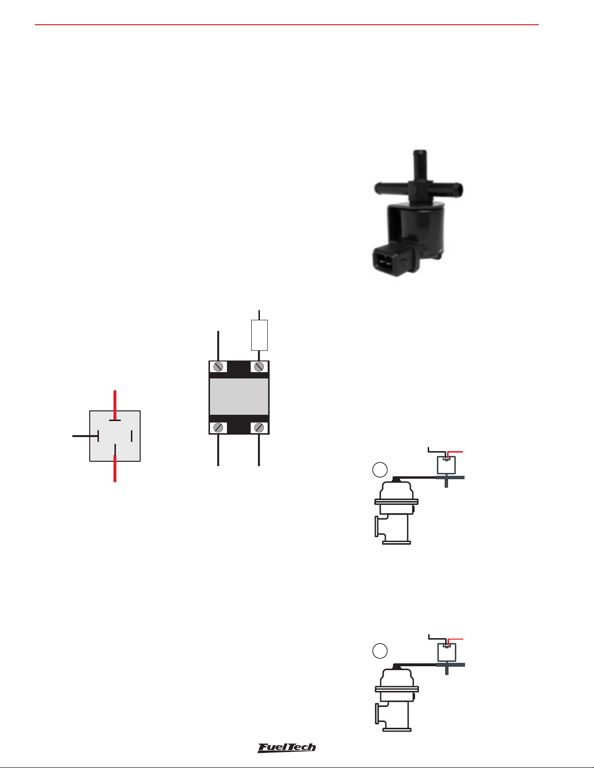
FT600
aux output
ree Air
aux output
wastegate
activation
+12V to load/actuator
12
Auxiliary outputs
requires a minimum impedance of 25Ω, or the use of a relay. For valve
timing control systems switched by PWM (such as Toyota’s VVTi), it
is possible to manage it through the Boost Control function, as long
as its characteristics (power, current, etc.) are within the auxiliary
output limits.
This resource can also be used to switch the control solenoid from the
2-speed automatic gear control, Powerglide type. Configure the RPM
to turn on the solenoid responsible for engaging the second gear, only
for drag racing applications.
13.7 Progressive nitrous control
This function drives the solenoids used for the injection of nitrous
oxide in the engine.
As these solenoids have high power (90W) and low impedance
(~1.6Ω), they cannot be connected directly to the auxiliary output.
A solid state relay with appropriate max current and voltage must be
used to power the nitro and fuel solenoids.
Set the output as progressive nitrous output.
Solid State
Relay HELLA
Ground
In the second option, the fogger only injects nitrous (dry nitrous). Fuel
enrichment is managed by the injection, increasing injection times
based on what has been programmed. The dry nitrous system has
reached better results in tests, giving the engine a more linear power
than the first option. It is important to clarify that in order to use the
dry nitrous system, the fuel injectors must be correctly sized for the
power maximum with the nitrous system operating.
There is a difference in the operation of solenoids that control nitrous
injection and the ones that control fuel injection: nitrous solenoid starts
pulsing after 5%; fuel solenoid only pulses after 20%. Variations may
occur among solenoids from different brands/manufacturers.
When applying the conventional nitrous control, one must start with
a minimum injection time of 20%, but when using dry nitrous, it is
possible to start with 5%, as the injectors – and not the solenoid – will
control fuel injection.
46
87
86
30
Switched power
12/16V (use fuse)
85
Do not
connect
Battery
Solid State
Relay CRYDOM
Output
(yellow
+12V
Solid state
-
4
ECU
wire)
relay
Switched
Nitrous
+
3
+12V
13.8 Boost Control – N75
This auxiliary output configuration allows the driving of a boost
pressure control solenoid. FuelTech recommends using a 3-way N75
solenoid, found in the original 4 and 5-cylinder
VW/Audi Turbo models, which can be directly switched through the
auxiliary output. Such solenoid valve controls the pressure on the top
and bottom parts of the wastegate valve, changing the engine manifold
pressure with which the latter opens.
N75 Solenoid Valve
VW 058-906-283F
Wastegate at the exhaust manifold
This type of valve is used on most cars with adapted turbo, in
competitions, etc.
Solenoid
Example 1: the first way to install a boost valve is connecting it to the
bottom of wastegate valve, similar to the OEM installing in the VW 1.8T.
Select the output signal as activated at 0V and frequency at 20Hz.
This way the boost valve will decrease the pressure under the
wastegate to increase boost pressure.
Boost controller
1
From boost pipe
From boost pipe
wastegate
output
Wastegate
Example 2: the second way is to connect the boost solenoid to the
top of wastegate.
Select the output signal as activated at 12V and frequency at 20Hz.
This way, the boost valve will increase the pressure at the top of
wastegate to increase boost
Boost controller
2
Wastegate
output
From boost Pipe
From boost Pipe
12V
N75
Free Air
12V
N75
F
Page 47
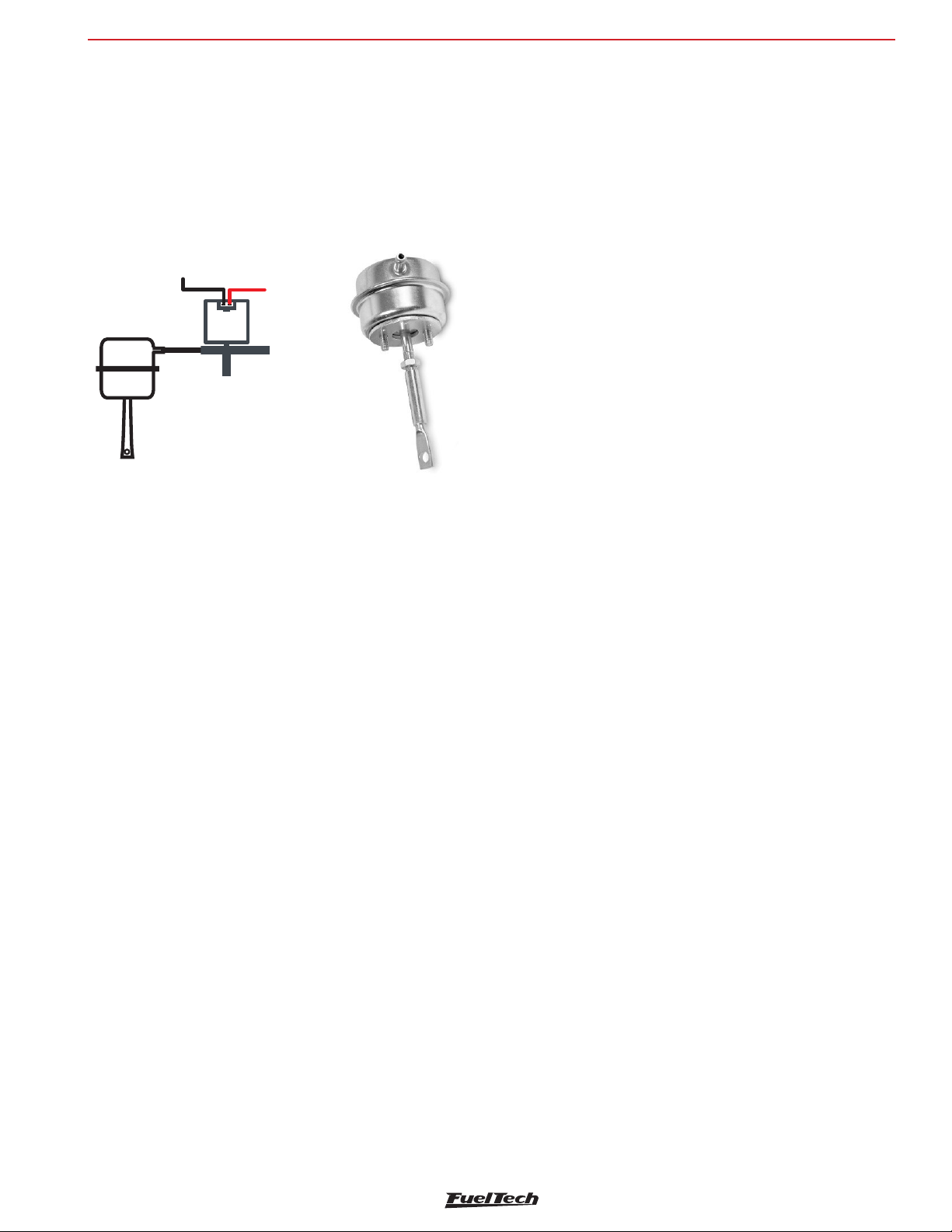
Auxiliary outputs
Wastegate integrated to the turbine
This valve has a different operation system, as it relieves the boost
pressure when pressure is put on its top part, which is the opposite
of what happens to the wastegate installed at the exhaust manifold.
Select the output signal as activated at 0V and frequency at 20Hz
With this kind of wastegate, the boost valve relieves the pressure in
top of wastegate to increase boost pressure
aux output
Boost controller
12V
N75
Free Air
From boost Pipe
Integrate
Wastegate
FT600
13.9 BoostController
The BoostController is used for more precise control of the turbo
pressure in street cars, circuit and drag races. The control can be
performed by time after 2-step, RPM and gear, gear and time after
change, unique value and engine RPM, as well as the control with
specific targets for drag race (2-step, 3-step and burnout).
See more information in chapter 19.15 BoostController diagrams.
47
Page 48
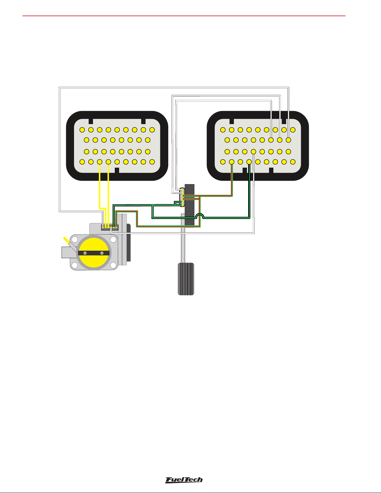
FT600
5V su fororspplysens
F 600T
Connectors rear view
Con ectornA
26
27
28
29
15 16
17
18 19 20
21 22
23 24 25
26
27
28
29
30 31 32 33 34
14. Electronic throttle control
Electrical installation of an electronic throttle on FT600 is pretty simple. Check the example diagram below:
Electronic throttle control
White Input#-10
12
10
11 12
18 19 20
3
Yellow output#- 3
4
13
21 22
Yellow output#- 4
5
6789
15 16
14
30 31 32 33 34
17
23 24 25
White input#-9
White Input#-8
Green Red-/
Green Black roundSensors g-/
Co nector Bn
12
10
11 12
White Input#-11
5
3
4
13
6789
14
• Yellow wire #3 (pin 13 of the connector A) must be connected
• Yellow wire #4 (pin 14 of the connector A) must be connected
• Green/red wire (connector B) is and 5V output used to feed
• Sensors negative can also be spliced between pedal and throttle
• White numbered wires are sensors signal inputs, connect them to
to the throttle input corresponding to the Motor 1 input.
to the throttle input corresponding to the Motor 1 input.
throttle and pedal position sensors. It must be spliced and
connected to both of them.
position sensors. Connect it directly to the battery’s negative
terminal.
the signal outputs of the pedal (Pedal 1 and Pedal 2) and throttle
(TPS1 and TPS2). After connecting these inputs, it is necessary
to calibrate throttle and pedal as guides chapter 15.1.
• Pins 26 and 27 (connector A), yellow wires, will not be used for
electronic throttle control, they can be set up as auxiliary outputs..
14.1 Connection table – throttle bodies and pedals
Check the throttle and pedal wiring before disconnect it from the OEM
ECU. If you need, contact our tech support to get more information
about throttles and pedals.
With the electrical connections ready, go back to chapter 7.5 and insert
the throttle code (FT) that you found on the throttle table connection
If your throttle is not listed in our table, it might be necessary to send
it to our tech team to have them check compatibility and research
its control parameters. In this case please contact our tech support.
48
Page 49
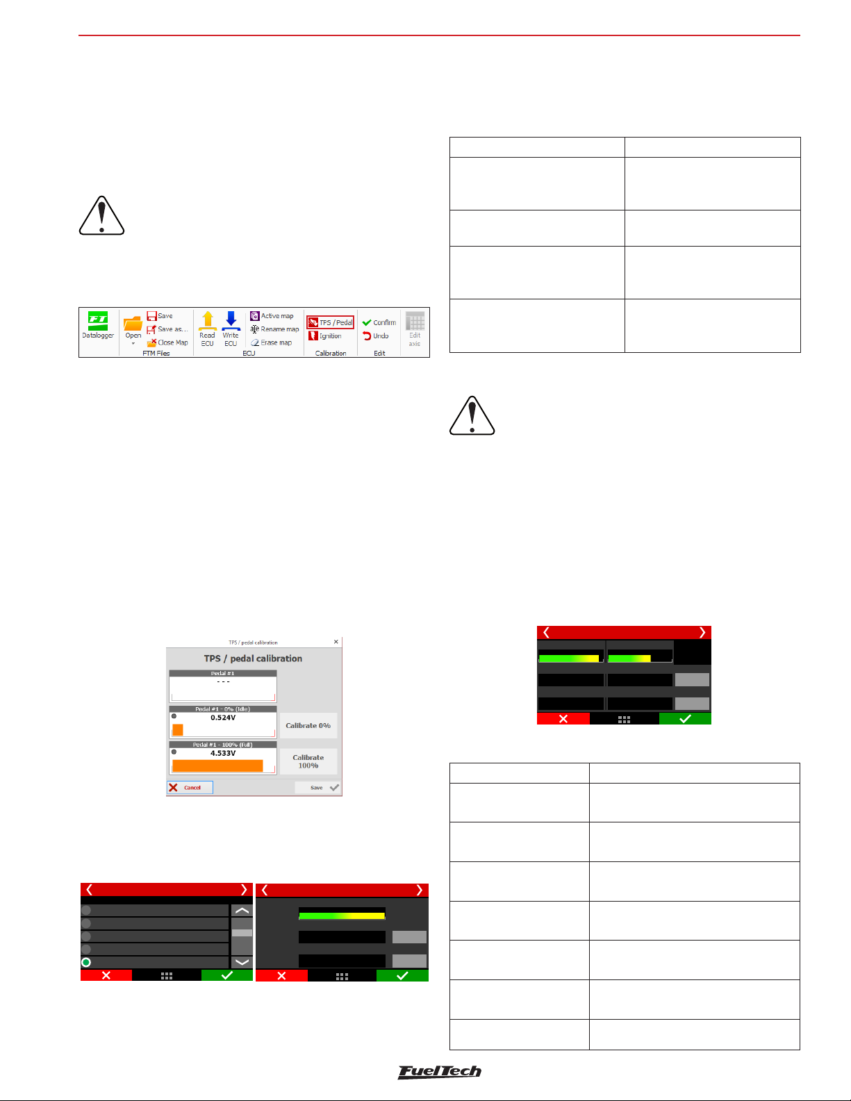
Sensors and calibration
FT600
15. Sensors and Calibration
This chapter has the final steps before the first engine start. It basically
guides the user through checking sensor readings and calibrating
engine actuators.
15.1 TPS calibration
IMPORTANT:
To perform this calibration, it is very important
that the engine is not running, because the
throttle is fully opened and closed
Through FTManager, click in the TPS/Pedal button
Go to “Sensors and calibrations” and then “Calibrate throttle/pedal”.
1. With the pedal on idle position, click button “calibrate” beside
the field “Idle: 0%
2. Push throttle to the maximum and click “calibrate” button beside
the field “WOT: 100%”.
3. Press “Save”. Message “Calibration done!” is shown if the process
is ok.
4. In case an error message is shown, check TPS connections.
TPS calibration errors may be:
Inverted and calibrated: means the TPS is connected the wrong way,
but is working normally. Double check connections, but, know that it
will work normally connected this way.
TPS signal voltage must go up, as the pedal is pressed, and must have
at least a 3V difference between the idle and WOT positions
TPS errors and diagnostics
Error message Diagnostic
TPS range must be higher than
1.5 Volts
TPS signal may be shorted to
ground
TPS signal may be disconnected
TPS calibration is required only
when activated
The TPS value from 0% to
100% has a smaller difference
than 1,5V
Ground short circuit for TPS input
TPS input disconnected or short
circuited to 5V
No input configured as TPS.
15.2 Electronic throttle/pedal calibration
IMPORTANT:
Every time the pedal calibration is done the
throttle automatically calibrates its opening
limits. It is very important that during this
calibration the engine is turned off because the
throttle is fully opened and closed.
This calibration procedure is exactly the same as the mechanical throttle
calibration. The only difference is that the calibration screen shows
voltage value on both TPSs of the electronic pedal.
With this done, it is necessary to adjust idle speed control parameters
as guides chapter 19.2
TPS/pedal calibration
Pedal #1
4.05V
4.99V
4.99V
Idle 0%
Full 100%
Pedal #2
2.01V
4.99V
4.99V
Calibrate
Calibrate
Possibly disconnected: check TPS connections. Maybe there is a
broken wire or one of the connectors does not reach the TPS pins.
Check with a tester to see if the voltage on the orange wire varies
according to the throttle position.
Input selection
White 7: Two step
White 8: Avaliable
White 9: Avaliable
White 10: Avaliable
White 11: TPS
TPS/pedal calibration
TPS/pedal calibration
Pedal #1
4.99V
Idle 0%
2.00V
Full 100%
4.99V
Calibrate
Calibrate
TPS sensor must be calibrated on the first time the ECU is turned on
only, and should be recalibrated only when it has to be replaced or the
throttle opening on idle was changed. TPS calibrations are individual
by map file.
Throttle body error and diagnostic messages
Error Message Diagnostic
Throttle #1 channels not
found
ETC motor #1 signals
may be disconnected
Throttle #1A signal may
be shorted to ground
Throttle #1A signal may
be disconnected
Throttle #1B signal may
be shorted to ground
Throttle #1B signal may
be disconnected
ETC 1 code error Throttle code error
There is no input configured as throttle
input
ECU Failed to actuate the throttle motor
Throttle Input A short circuited to GND
Throttle input A disconnected or short
circuited to 5V
Throttle Input A short circuited to GND
Throttle input A disconnected or short
circuited to 5V
49
Page 50
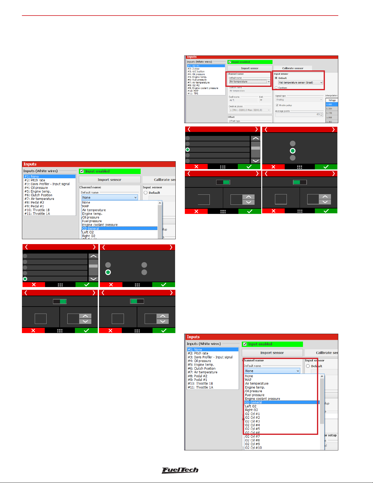
FT600
Sensors and calibration
15.3 Fuel/oil pressure sensors inputs
In this menu are the settings for fuel and pressure sensors. There is
a predefined configuration for PS-150/300/1500 pressure sensors,
but any kind of analog sensor with 0-5V signal can be used. This
configuration is done through the PC and software FTManager.
In case there is a reading error between the FT600 screen and
the real value of the sensor (comparing to an external gauge), this
compensation is easily done by adjusting the sensor offset. It is possible
to edit this compensation in mV or in pressure offset. Just change
the button on the top part of the screen between “Input value” (mV
adjust) and “Output value” (pressure offset). The field “Read value”
shows readings in real time.
Make sure your external gauge is correctly calibrated and that the
correct sensor is selected, as incorrect use of this function can cause
significant error in pressures reported.
Make sure your external gauge or dashboard is correctly calibrated
and that the correct sensor is selected, as incorrect use of this option
can cause significant error in reported temperatures and possible
engine damage
Input selection
None
....
White 7: Avaliable
White 8: Pedal #2
White 9: Pedal #1
Input value
Reading
89,0
Air temperature 1/3
Air temperature 3/3
°C
Output value
Sensor offset
-9
°C
Air temperature 2/3
Temperature sensor type
FIAT
GM
Custom
Air temperature 3/3
Input value
Reading
89,0
°C
Output value
Sensor offset
+10,7
mV
Input selection
None
White 1: Avaliable
White 2: Two-step
White 3: Air conditioning
White 4: Avaliable
Input value
Reading
49,0
bar bar
Oil pressure 1/3
Oil pressure 3/3
Output value
Sensor offset
0,10
bar
Oil pressure 2/3
Pressure sensor type
PS10A
PS10B
Oil pressure 3/3
Input value
Reading
49,0
bar
VDO
Custom
Output value
Sensor offset
32
mV
The FT600 has fully customizable inputs, which allows to read any
0-5V analog pressure sensor, since its pressure vs voltage table
is known. In this case, just select the custom option and fill the
interpolation table through FTManager.
15.4 Intake air and engine temperature sensors
In this menu are the settings for intake air and engine temperature
sensors. There is a predefined configuration for GM and Fiat sensors.
The FT600 has fully customizable inputs, which allows to read any
0-5V analog temperature sensor, since its temperature vs voltage
table is known. In this case, just select the custom option and fill the
interpolation table through FTManager.
15.5 O2 sensor inputs
O2 sensor signal input can be setup on any sensors input of this
FT600 it is even possible to read fifteen O2 sensors simultaneously and
show them on the screen. For wide band O2 sensors, it is necessary
to use a wide band conditioner, for narrow band O2 sensors, direct
connection is allowed.
Be sure to connect the O2 conditioner to FT600 according to the
Chapter 12.7 of this manual.
In case there is a reading error between the FT600 and the real value
of the sensor (comparing to an external gauge or to the dashboard),
this compensation is easily done by adjusting the sensor offset. It is
possible to edit this compensation in mV or in degrees. Just change
the button on the top part of the screen between “Input value” (mV
adjust) and “Output value” (temperature offset). The field “Read value”
shows readings in real time.
50
Page 51
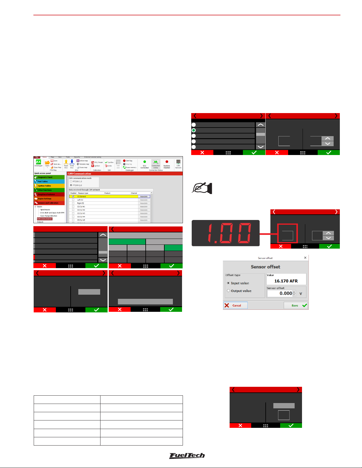
Sensors and calibration
FT600
CAN network reading
Through CAN network the reading is sent directly to FT600, the only
configuration necessary is to indicate what is the position of each
sensor, this procedure is called “association”.
The association procedure is executed by disconnecting from the
conditioner a single sensor at time, this way the FT600 identifies
and associates that sensor to the position of the engine (cylinder 1,
general O2 sensor).
Follow the steps and repeat for each O2 sensor:
1. Keep the conditioner connected and turned on and disconnect
the O2 sensor;
2. Press the Associate button on FT600 or on the “CAN
communication of FTManager” window;
3. Reconnect the O2 sensor and repeat the process for all other
O2 sensors;
WB-O2 Nano, Slim or Datalogger calibration
Offset calibration is needed to compensate analog signal loss. With
O2 sensor connected and configured go to “Calibrate O2 sensor”
(through display) or click in “Calibrate sensor” in FTManager software.
To calibrate O2 sensor, proceed as follows:
1. Check the scale of FT600 with external conditioner, they must
be equal.
2. With the engine running, stabilize the O2 reading.
3. Adjust the offset until the reading in the conditioner matches the
reading in the ECU.
Input selection
Narrowband O2 1/2
None
White 1: Avaliable
White 2: Pitch rate sensor
White 3: Davis profiler input
White 4: Oilpressure
4. If the calibration and configuration are correct, there will be no
reading difference.
NOTICE:
If the difference is greater than 0.02 between the
readings, it means that the scales are different.
Narrownband O2 2/2
O2 sensor calibration
Reading
0,87
λ
Sensor offset
+0,36
volts
Sensors and Calibration
Fuel pressure
Air temperature
Engine temperature
NarrowBand O2
WideBand O2
General 2/3
CAN equipment to:
CAN ID: --Model: --CAN Port: --Input: ---
General
Associate
Cylinder 1
Cylinder 5
Cylinder 9
The reading will be associated to this position.
Wideband O2
General
Left bank
Cylinder2
Cylinder6
Cylinder10
General 3/3
Make sure only 1 sensor is disconnected.
Associate
Right bank
Cylinder 3
Cylinder 7
Cylinder 11
Cylinder4
Cylinder8
Cylinder12
Analog input reading
The O2 sensor reading through an analog input is used either to narrow
band or wide band with conditioners that have analog output (FuelTech
WB-O2 Slim WB-O2 Nano WB-O2 Datalogger and Alcohol O2), Simply
set the sensor in any input of FT600 (white wires).
It’s necessary to set the input scale according to the analog output of
conditioner used. If it’s a FuelTech conditioner select one of the preset
scales. For other manufacturers use the custom table. The narrow band
sensor reading is displayed directly in Volts.
Analog scales compatible with the FT are:
Scale Output voltage
0,35 - 1,20 0,35 = 0,2V - 1,20 = 4,8V
0,59 – 1,10 0,59 = 0,2V – 1,10 = 4,8V
0,65 – 1,30 0,65 = 0,2V – 1,30 = 4,8V
0,65 – 4,00 0,65 = 0,2V – 4,00 = 4,8V
0,65 – 9,99 0,65 = 0,2V – 9,99 = 4,8V
Sonda Lambda 1 3/XX
O2 Sensor #1 3/3
Calibração da Sonda Lambda
O2 sensor calibration
Valor lido
Reading
0,87
1,00
λ
λ
Ajustar offset do sensor
Sensor offset
+0,36
3
volts
mV
Alcohol-O2 Calibration
Also called free air calibration, this calibration is necessary when using
FuelTech Alcohol O2 conditioner to compensate for differences in each
sensor. When replacing a sensor it’s necessary to repeat this calibration.
1. Remove the sensor from the exhaust pipe and let it ventilate for
at least 20 seconds;
2. Press the calibrate button;
3. Calibration is ok;
O2 Sensor #1 3/3
Alcohol O2 calibration
Before starting
the calibration the
probe must be removed
from the exaust pipe
and kept in free air for
20 seconds
Calibrate
2,87
V
51
Page 52
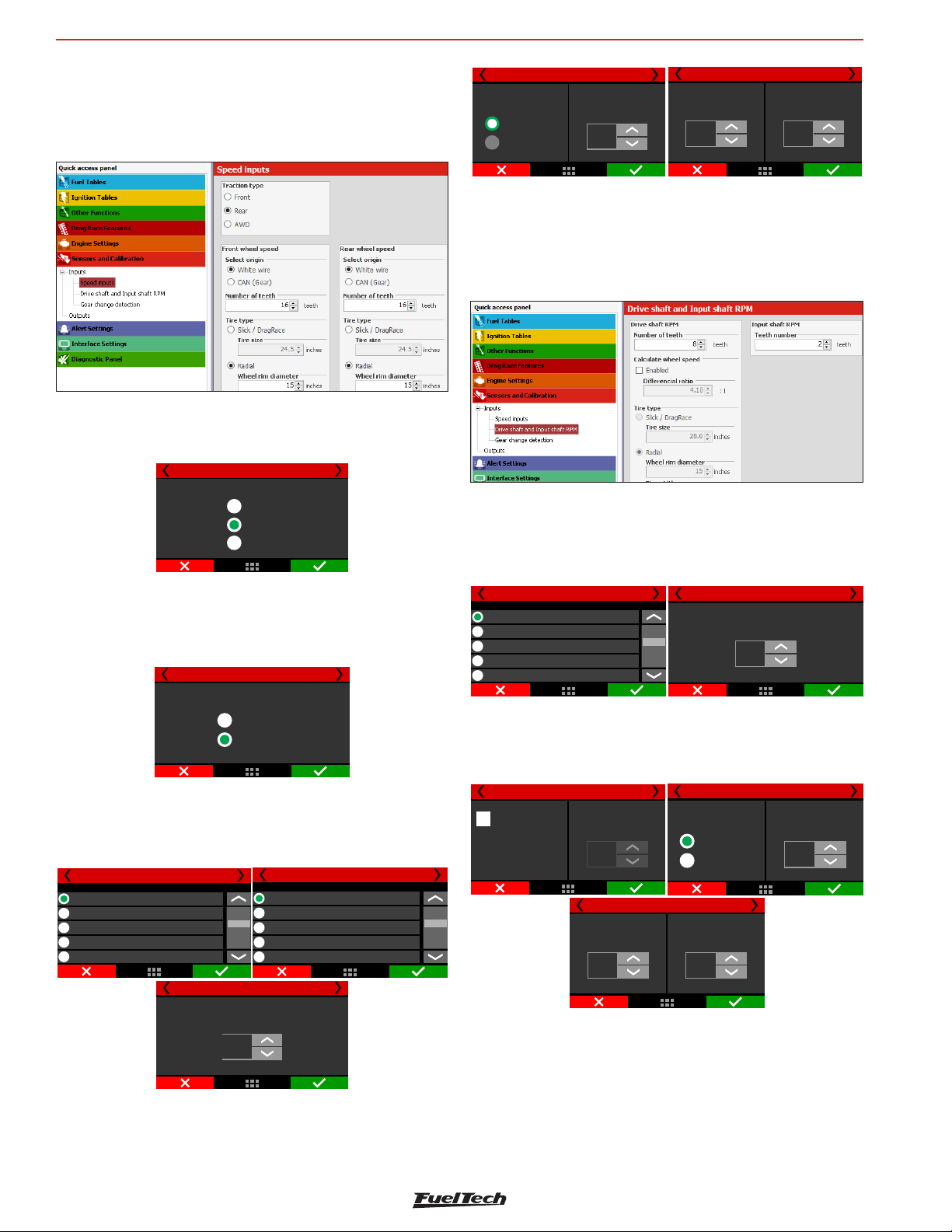
FT600
Sensors and calibration
15.6 Speed inputs
In the FTManager, there is a menu with all the settings related to wheel
speed reading. In the touchscreen, the settings are divided in a few
submenus and will be presented in the next chapters.
Traction type
Set here if the vehicle is FWD, RWD or AWD. This information is used
with the time based speed control.
Traction type
Front
Rear
AWD
Wheel speed (front/rear)
This menu gathers the wheel speed (front and rear) reading setup.
In the first screen, set if the reading is through FT600 sensor input
(white wire) or through FuelTech GearController CAN port.
Rear wheel speed 1/6
Select origin
White wire
CAN (Gear)
If the chosen option is “White wire”, the configuration screens will be
shown to set the sensor input to left and right wheels, and number of
teeth. The next screens will not be displayed when the CAN option
is chosen.
Input selection
Rear left wheel 2/6
None
White 1: O2 sensor #1
White 2: 2-step
White 3: Air Conditioning
White 4: Oilpressure
Rear wheel speed 4/6
Rear right wheel 2/6
Input selection
None
White 1: O2 sensor #1
White 2: 2-step
White 3: Air Conditioning
White 4: Oil pressure
Rear wheel speed 5/6
Tire type
Radial
Slick/DragRace
Wheel rim diameter
17,0
in
Rear wheel speed 6/6
Tire width
225
mm
Tire height
45
%
15.7 Driveshaft RPM and Input shaft RPM
In the FTManager, there is a menu with all the settings related to
driveshaft RPM and input shaft RPM reading. In the touchscreen, the
settings are divided in a few submenus and will be presented in the
next chapters.
15.8 Driveshaft RPM
This menu is used to setup the driveshaft RPM reading. Select the
FT600 sensor input to be used and insert the trigger wheel number
of teeth
Input selection
Driveshaft RPM 1/5
None
White 1: O2 sensor #1
White 2: 2-step
White 3: Air Conditioning
White 4: Oilpressure
With the driveshaft speed and the tire dimensions, it is possible to
calculate the traction wheel speed. If you want to use a driveshaft
RPM sensor instead of a wheel speed sensor, check the box “Calculate
wheel speed” in the next screen.
Driveshaft RPM 3/5
Calculate wheel
speed
This configuration helps
to calculate wheel speed
using the differentialratio.
*Often used to replace
the wheel speed sensor.
Differencial ratio
4,10
:1
Driveshaft RPM 5/5
Tire width
225
mm
Driveshaft RPM 2/5
Number of teeth
Driveshaft RPM 4/5
Tire Type
Radial
Slick/DragRace
Tire height
45
%
teeth
8
Wheel rim diameter
17
in
Number of teeth
8
Teeth
The last setting is related to tire type and size. Slick/Drag Race tires
only require the wheel rim diameter. Radial tires require wheel rim
diameter, tire width and height.
52
To calculate wheel speed, insert the differential ratio and tire
dimensions.
The last setting is related to tire type and size. Slick/Drag Race tires
only require the wheel rim diameter. Radial tires require wheel rim
diameter, tire width and height.
Page 53
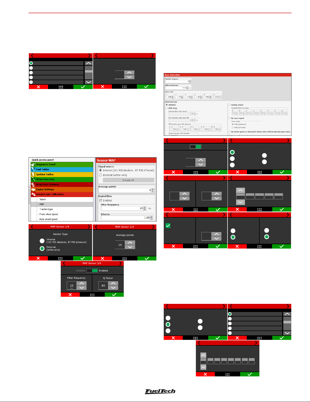
Sensors and calibration
Gearbox RPM 1/2
White 1: O2 sensor #1
Input selection
None
White 2: 2-step
White 3: Air Conditioning
White 4: Oilpressure
FT600
15.9 Gearbox RPM
This feature allows the gearbox input shaft RPM Reading.
The reading is very useful to analyze the clutch/torque converter slip.
Just insert the sensor input and the number of teeth
Gearbox RPM 2/2
Number of teeth
2
Teeth
15.10 MAP Sensor
This menu allows to setup the internal MAp or an external one.
Internal MAP: Can read up to 87 PSI and it's average points and Q
factor can be changed for smoother readings on engines with high
cam profiles.
External MAP: Can usually read pressures higher than 87 PSI, a
white input must be used to setup an external MAP sensor for more
than 87 psi.
The first mode, by RPM drop, must be used only in drag race cars,
since it can only detect upshifts and not down shifts. The third screen
is for safety configurations, used to prevent false gear detection due
to traction loss. Default values are good to most cases.
The fourth screen is for the RPM drop programming to each gear. The
fifth screen is to enable and program the timeout for gear shift detection
that is another safety feature to prevent false detection.
Gear detection 1/5
Disabled
Number of gears
6
Enabled
Gear detection 2/5
RPM drop
Analog sensor
By wheel speed
or driveshaft
Detection Type
By input signal
Gear shift
based output
15.11 Gear detection
In this menu there are the settings related to gear detection change
(display and log). There are 5 different ways to detect it: by RPM drop
(drag race only), by gear position sensor (requires a sensor in the
transmission), by interpolating the current wheel speed versus engine
RPM, by pulse and by gear shift output.
To view the currently engaged gear in the FT600 dashboard, go to
“Interface Settings” and then “Dashboard Settings”. Once in, click in
the cell where you want to display the gear and select “Gear”.
Gear detection 3/5
Detection block
after launch
0,50
s
Gear detection 5/5
Timeout for gear
shift detection
Gear count is increased
whenever engine RPM
stays above the gear shift
RPM for the time
setup beside.
Block detection
after gear shift
0,50
s
wait time for
gear shift detection
1,00
s
Gear detection 4/5
RPM drop for gear shift detection
3 - 4
2 - 3
1 -2
200
Gear reset
2-Step
External button
200
200
Gear detection 6/7
4 - 5
200
200
Button mode
Activated at 0V
Activated at 12V
5 - 6
The second mode reads an analog gear position sensor, which is a
potentiometer that indicates the engaged gear in transmissions already
equipped with this sensor. Select the input that will read the sensor
signal and then configure each gear voltage
To find the gear voltage, use a multimeter, in 20VDC scale, connected
to the output of the gear position sensor and engage a gear at a time.
Gear detection 2/5
RPM drop
Analog sensor
By wheel speed
or driveshaft
Detection type
By input signal
Gear shift
based output
Gear detection 4/5
Analog level for each gear
N
R
1
0,2
0,0
0,4
1,2
2
2,032,8
None
White 1: O2 sensor #1
White 2: 2-step
White 3: Air Conditioning
White 4: Oilpressure
Gear detection 3/5
Selecione a entrada desejada
6
4
3,654,4
53
Page 54
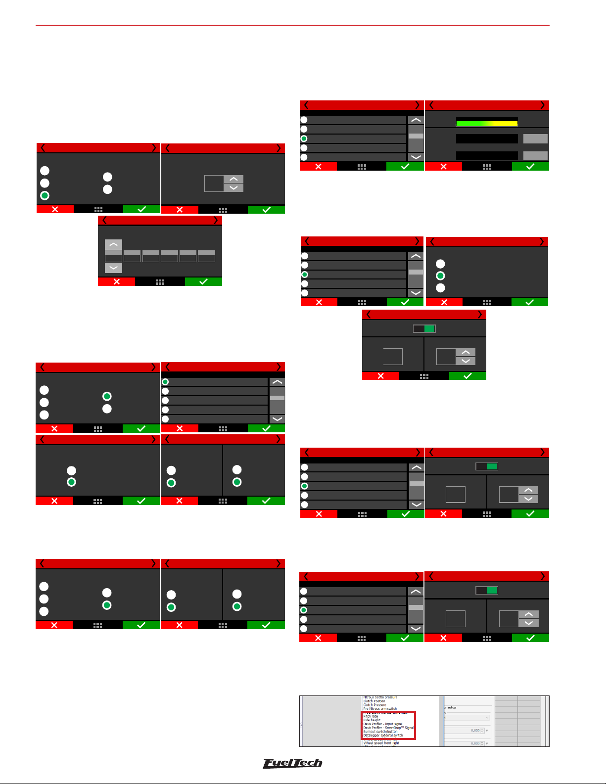
FT600
Sensors and calibration
The third mode crosses the wheel speed and RPM to calculate the
engaged gear.
To configure, set the number of gears, gearbox ratio and differential
ratio.
This detection mode will only show the engaged gear if the vehicle
is moving and there is wheel speed reading.
When the clutch is pressed or the gear is disengaged (neutral) your
FT600 may display an incorrect gear momentarily.
RPM drop
Analog Sensor
By wheel speed
or driveshaft
Gear detection 2/5
Detection type
1
2,56
By input signal
Gear shift
based output
2
1,73
Gear detection 4/5
Gear ratio
4
1,2631,00
Gear detection 3/5
6
0,8250,00
Differenctial
ratio
4,10
:1
The fourth mode increases the gear counting by each pulse received
on a white input. Set in which edge the count should be increased
(default: falling edge). Configure an input as “Gear Detection” and
connect the device that will send the pulse to increase the counting.
This mode cannot detect down shifts and requires the 2-step to be
used to reset the counter; therefore it is best suited for drag race cars.
Gear detection 2/5
RPM drop
Analog Sensor
By wheel speed
or driveshaft
Gear detection 4/5
Detection type
Signal edge
Rising edge
Falling edge
By input signal
Gear shift
based output
None
White 1: O2 sensor #1
White 2: 2-step
White 3: Air Conditioning
White 4: Oilpressure
Gear detection 3/5
Selecione a entrada desejada
Gear detection 6/7
Gear reset
2-Step
External button
Button mode
Activated at 0V
Activated at 12V
The fifth mode enables an internal counter that is increased by each
pulse sent out by the Gear shift output (Drag Race Features menu).
This mode cannot detect down shifts and requires the 2-step to be
used to reset the counter; therefore it is best suited for drag race cars.
Gear detection 2/5
RPM drop
Analog Sensor
By wheel speed
or driveshaft
Detection type
By input signal
Gear shift
based output
Gear reset
2-Step
External button
Gear detection 6/7
Button mode
Activated at 0V
Activated at 12V
15.12 Nitrous bottle pressure
This menu gathers the settings to read nitrous bottle pressure. This way
is possible do compensate fuel according to the bottle pressure. To read
the bottle pressure you must use a PS1500 sensor or a similar one.
15.13 Clutch position
In this menu are the settings to read the clutch position. A potentiometer
must be used, similar to a TPS. After the wiring done, the calibration
is required.
Input selection
White 7: Air temperature
White 8: Avaliable
White 9: Avaliable
White 10: MAP signal
White 11: TPS
Clutch position 1/2
Clutch position 2/2
Reading
4.99V
Position at 0%
4.99V
Position at 100%
4.99V
Calibrate
Calibrate
15.14 Clutch pressure
This function allows to measure the pressure of the liquid on hydraulic
assisted clutches. To read the pressure, use a PS1500 sensor or a
similar one.
Input selection
White 6: Fuel pressure
White 7: Air temperature
White 8: Avaliable
White 9: clutch
White 10: MAP signal
Clutch pressure 1/3
Clutch pressure 3/3
Input value
Reading
1350,0
PSI
Clutch pressure 2/3
Pressure sensor type
1450 PSI/PS100 (1,0 5,0V)a
1500 (0,5 a 4,5V)PSI
Custom
Output value
Sensor offset
+0,3
PSI
15.15 Ride Height
This function allows to read the front end height from the ground. The
wheelie control is based on this input and you can find more on this
at Chapter 20.9. Normally, a laser height sensor is used.
Input selection
None
White 1: O2 sensor #1
White 2: Avaliable
White 3: 2-step
White 4: Oilpressure
Ride height 1/2
Input value
Reading
3,5
in
Ride height 2/2
Output value
Sensor offset
+0,3
in
15.16 Pitch Rate
This function reads the rate at the front end pitches and is given by
degrees per second.
Input value
Reading
0,0
°/S
Pitch rate 2/2
Sensor value
Sensor offset
+0,6
°/S
Input selection
None
White 1: O2 Sensor
White 2: Pitch rate
White 3: 2-step
white 4: Oil pressure
Pitch rate 1/2
Through FTManager, all the sensors above can be configured in the
“Sensors and Calibration” menu, then “Inputs”.
54
Page 55
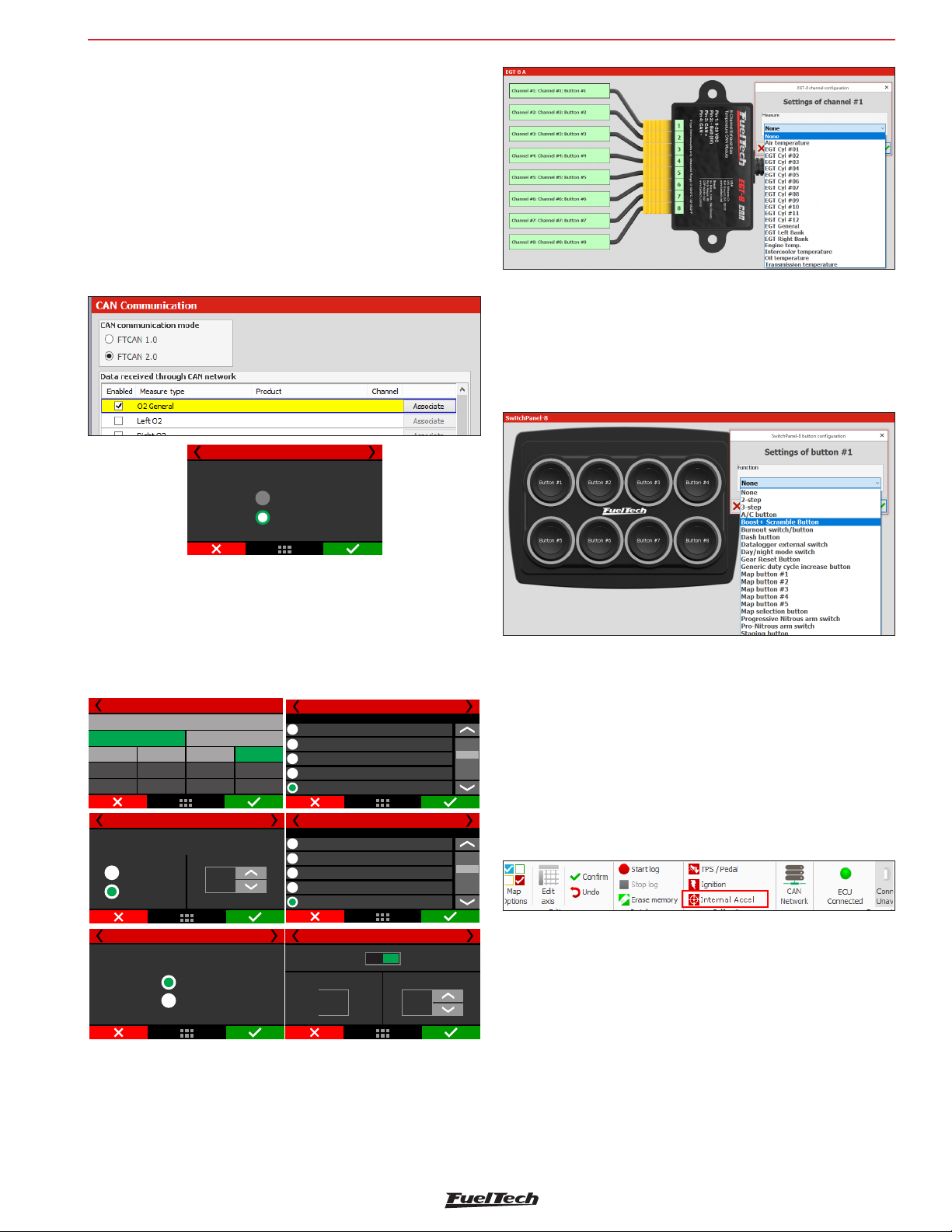
Sensors and calibration
15.17 CAN communication
In this menu is possible to configure all the equipment connected to
the CAN network. There are 2 different CAN protocols. Below is the
compatibility of each protocol:
- FTCAN 1.0: GearController (until V2.17), BoostController,
KnockMeter, Racepak IQ3 and AiM Dashes;
- FTCAN 2.0: GearController (after V2.20) EGT-8 CAN; WB-O2
Nano and WB-O2 Slim;
CAN network supports up to 32 sensors of each product.
- This option allows stock ECU data to be received through CAN
network.
CAN communication 1/2
CAN mode
FTCAN 1.0
FTCAN2.0
FT600
SwitchPanel-8 Configuration
This is an external panel with 8 buttons that are totally configurable
through FTManager via CAN Communication. Go to “Sensors and
Calibration / CAN Communication / SwitchPanel-8” click on the button
you want to configure and select one of the many preset functions
from the list.
15.18 EGT
This menu allows to setup the EGT conditioners (ETM-1 or EGT-8
CAN) and to perform the cylinder attribution. To do it, simply select
the cylinder where the EGT is placed and what is the conditioner.
The attribution can be done using the CAN network with EGT-8 CAN
or using the white wires inputs with ETM-1.
EGT
General
Left bank
Cylinder 1
Cylinder 5
Cylinder 9
Cylinder2
Cylinder6
Cylinder10
Channel association
Equipment Channel
EGT A
EGT B
Select the sensor type
Cylinder 3
Cylinder 7
Cylinder 11
Cylinder 4 2/3
Cylinder 4 2/3
ETM-1
Custom
Right bank
1
Cylinder4
Cylinder8
Cylinder12
Input selection
White 5: Avaliable
White 6: Avaliable
White 7: Avaliable
White 8: Avaliable
CAN 2.0
Input selection
None
White 1: Avaliable
white 2: Pitch rate
White 3: Davis profiler input
White 4: Avaliable
Input value
Reading
56,0
°C
Cylinder 4 1/3
Cylinder 4 1/3
Cylinder 4 3/3
Output value
Sensor offset
+10,7
°C
15.19 Wastegate Pressure
Setup the wastegate pressure sensor for use with the integrated
BoostController. For more information check chapter 19.16
BoostController.
15.20 Internal accelerometer
After the FT600 installation, the accelerometer calibration is needed
to avoid errors. It can be performed directly through the FT600 screen
or through the PC Software FTManager.
To perform the calibration, simply fix the ECU on it's place and click
the "Calibrate"button. The current position on the car will be saved the
default. If you wish to reset calibration, used the "Reset Calibration"
button.
There is even an accelerometer bias error used to correct mirror read
errors.
EGT-8 Settings
Since update 3.3 theres a new layout for setting the EGT-8 channels.
Access “sensors and Calibration / CAN Communication / EGT-8” an
image of the EGT-8 will be displayed, click on the channel you want
to configure and select wich sensor from the list will be associated
with this channel.
Accelerometer Bias Error: to set this bias is necessary to compare
the acceleration speed with front and rear wheel speed, the difference
will be the bias configuration.
55
Page 56
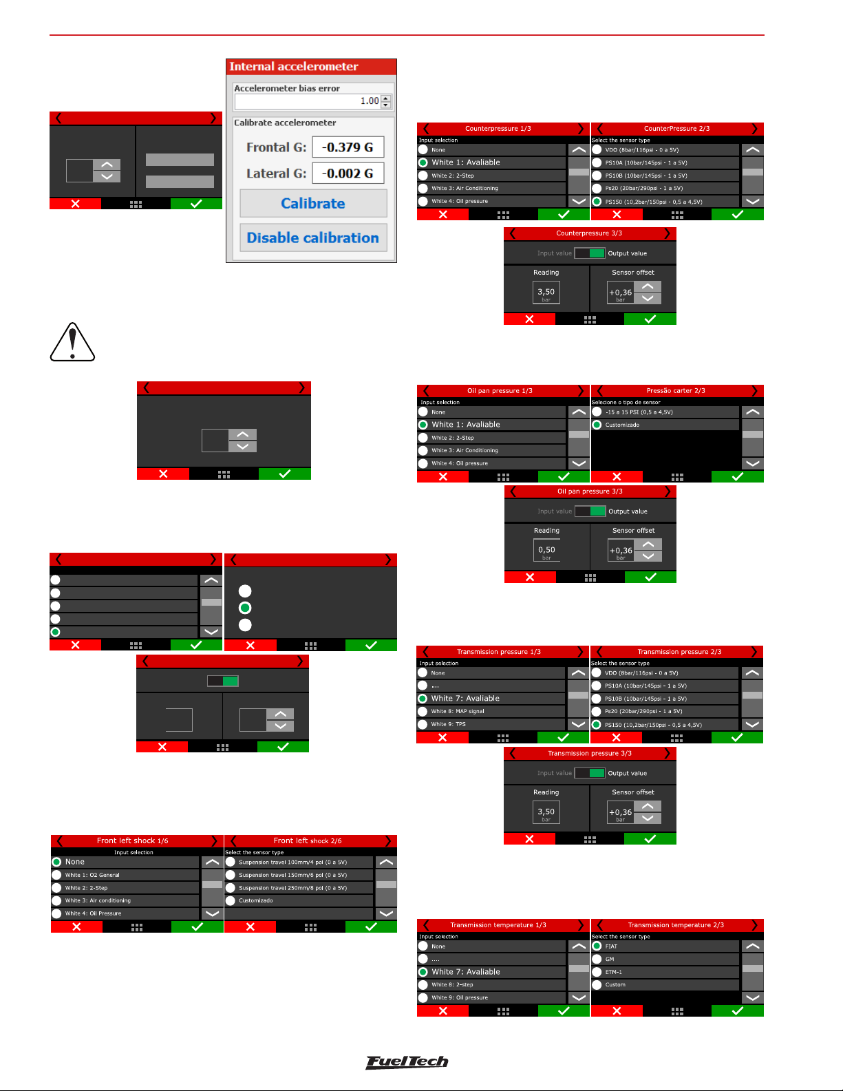
FT600
Input selection
Internal accelerometer
Frontal G: 0,5G
Accelerometer
bias error
1,26
Filter frequency: this filter is applied to the accelerometer to decrease
signal noise, resulting in a cleaner signal.
Lateral G: 0,0G
Calibrate
Disable calibration
IMPORTANT:
A greater filter frequency will result in signal reading
delay.
Internal Accelerometer 2/2
Filter Frequency
(Bandwith)
Sensors and calibration
15.24 CounterPressure
This function allows to set up a pressure sensor to be used on the
exhaust to measure back pressure.
15.25 Oil pan pressure
Udes to measure pressure inside the oil pan.
31,25
Hz
15.21 Brake Pressure
This function configures a sensor input for brake pressure control,
helping the line lock function.
None
WhiteAvaliable1:
White2: Two Step
White Air temperature3:
White Avaliable4:
Brake Presusre 1/3
Input value
Reading
1350,0
PSI
Brake pressure 3/3
Brake pressure 2/3
Select the sensor type
1450 PSI/PS100 (1,0 5,0V)a
1500(0,5 a 4,5V)PSI
Custom
Output value
Sensor offset
+0,3
PSI
15.22 Front and rear shocks
This function allows to set the range for the sensor used on each
wheel to measure suspension travel.
15.26 Transmission pressure
Monitors the pressure inside the transmission.
15.27 Transmission temperature
Allows to set a sensor to measure the oil temperature
15.23 Flex Fuel
This function allows the use of a GM Flex Fuel sensor to measure the
ethanol density that the gasoline has on the fuel line.
56
Page 57
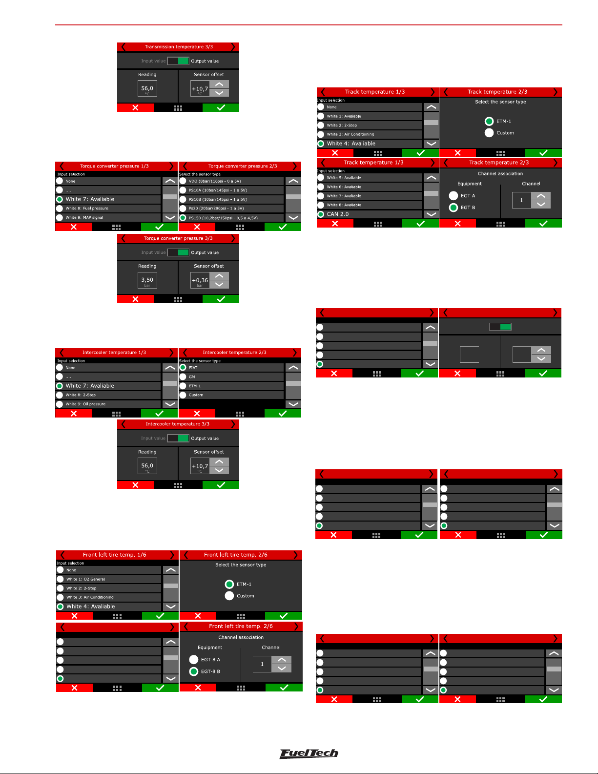
Sensors and calibration
rb
15.28 Torque converter pressure
This function allows to set up a pressure sensor to be used to measure
torque converter pressure.
FT600
15.31 Track temperature
Allows to monitor track surface temperature using a lazer sensor with
either an ETM-1 wired into a white input or an EGT-8 via CAN.
15.32 Engine Coolant pressure
This function it is possible to configure a sensor for monitor of
the pressure to the engine cooling system. Set the sensor used if
necessary, to adjust the offset.
15.29 Intercooler temperature
Used to monitor intercooler temperature.
15.30 Front and rear tires temperature
Allows to monitor tire temperature using a lazer sensor with either an
ETM-1 wired into a white input or an EGT-8 via CAN.
Selectg Input
None
White 1: Avaliable
White 2: Two Step
White 3: Air temperature
White 4: Avaliable
Low Beam 2/4
Select sensor
Engine coolant pressure
VDO (8bar/116psi- 0 a 5V)
PS10A (10bar/145psi- 1 a 5V)
PS10B (10bar/145psi- 1 a 5V)
Ps20 (20bar/290psi- 1 a 5V)
PS150 (10,2bar/150psi - 0,5 a 4,5V)
Engine coolant pressure 3/4
Input value
Reading
3,50
ba
Outpu value
Offset sensor
+0,36
bar
ar
15.33 Conversion light
Set an input for each conversion light (left and right) to set whether
the drive will be 0V or 12V.
Access the “Interface Configuration” menu then “LED Configuration” to
adjust the conversion lamp drive indication LED. For more information,
see chapter 23.
Left conversion light 1/4
Select Input
None
White 1: Avaliable
White 2: Two Step
White 3: Air temperature
White 4: Avaliable
Right conversion light 3/4
Select Input
None
White 1: Avaliable
White 2: Two Step
White 3: Air temperature
White 4: Avaliable
15.34 Low beam / High beam
Set one input for the low beacon and one for the high beacon, set
whether the drive will be 0V or 12V.
Access the “Interface Configuration” menu then “LED Configuration”
to adjust the high and low headlight drive indication LED. For more
information, see chapter 23.
Selectg Input
None
White 1: Avaliable
White 2: Two Step
White 3: Air temperature
White 4: Avaliable
Low Beam 2/4
Select Input
None
White 1: Avaliable
White 2: Two Step
White 3: Air temperature
White 4: Avaliable
High Beam 3/4
57
Page 58
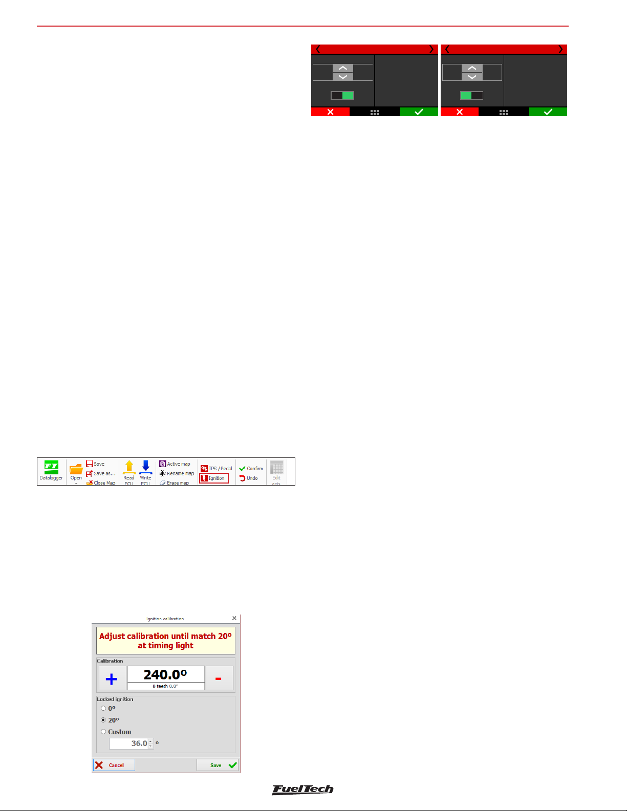
FT600
Starting the engine for the first time
16. Starting the engine for the first time
This chapter shows final steps before the engine first start and guides
the user through checking and calibrating all the sensors and actuators
of the motor.
16.1 First engine start
Try not to stress the starter motor by cranking too long on the make
the first start. Check if the fuel pump is turned on and if there is fuel
pressure on the line. Check if the FT600 reads the correct RPM in its
dashboard and make sure there’s spark on the spark plugs (unplug
the spark plug wires and install a spark plug on it to check for spark).
On engines fueled with ethanol or methanol, use a squirt of gasoline
into the throttle body to make the first start smooth.
When the engine starts, keep it at a fast idle and double check oil
pressure and the coil and igniter temperature.
Check if the RPM is being correctly shown on the ECU display (if
possible, compare to an external tachometer) and if throttle variations
coincide with TPS and vacuum readings.
16.2 Ignition calibration
Once the engine has started, before any kind of test or tune, the ignition
calibration must be performed. This calibration is very important to
make sure the timing the ECU reads is really correct with the engine.
This function locks the timing to 20° (or 0°) on any RPM, this means,
if the engine starts but has no idle, you can rev it up and keep it in
something around 2000rpm to perform the calibration. Avoid RPM
variations as this causes variations on the timing light readings.
100,1
°
Locked ignition
0° 20°
Ignition calibration
Adjust calibration
25
dentes
until match 20° at
+3,2º
(Some timing light
may read 40°)
timing light
100,1
°
Ignition calibration
+3,2º
Locked ignition:
0° 20°
Teeth
25
Adjust calibration
until match 0° at
timing light
Ignition calibration with crank trigger: Cars originally equipped
with crank triggers, usually do not have the TDC mark. This mark
then should be done by stopping the engine on cylinder #1 TDC of
compression using a dial-comparator. It is very important to be precise
when making this timing mark; the slightest error will ultimately affect
ignition timing on the engine
In these systems, usually the ignition is controlled on wasted spark, with
one spark on the combustion stroke and one on the exhaust stroke.
As the timing light reads both sparks, it usually shows 40° BTDC of
timing, but the actual timing is 20° BTDC.
As it is not possible to turn the crank trigger as we do on distributor
systems, the ignition calibration screen has a compensation that
must be changed until the timing light shows 20° BTDC (or 40°,
according to the timing light). Let’s say you read a timing of
24°BTDC, a compensation of -4° is needed to read 20° BTDC on
the crankshaft TDC mark. When the timing light is reading double the
real timing (wasted spark), if the timing on the timing light is 46º, the
compensation that must be set is -3º, instead of -6º.
To check if your timing light is reading twice the real timing, advance 5°
and check the timing on the engine again. If the timing has advanced
10°, the timing light is reading double the real timing.
The access to this function is given by the “Ignition” button in the
main FTManager menu or the “Calibrate ignition” in the touchscreen
“Sensors and Calibration” menu
Ignition calibration with distributor: On the engines originally
equipped with distributor, there’s a TDC mark for cylinder #1. Point
the timing light and turn the distributor until the timing light reads
20°. Lock the distributor then press “OK” button on the ECU. Ignition
calibration is finished
58
Page 59
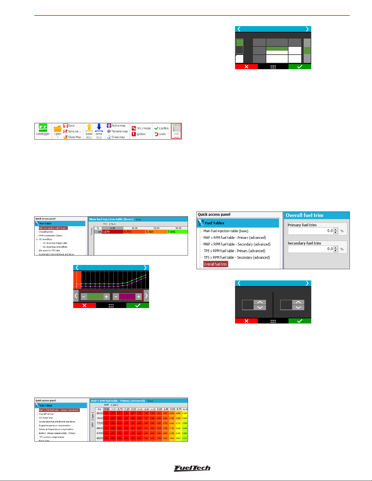
Fuel tables adjust
FT600
17. Fuel tables adjust
17.1 Main fuel table
Editing mode for main fuel table is set as 2D basic mode by default,
but it is possible to switch to advanced 3D mode. To change parameter,
in the FTManager, go to “Advanced map options” in the “Engine
settings” menu.
On FTManager, it is possible to edit the map cell ranges of MAP/TPS,
RPM, etc., making it possible to increase the detail level on the maps
where a fine tuning is needed. To do it, simply click on “Edit axis” on
FTManager tool bar.
Basic Mode - 2D table
In the basic mode, the engine is tuned according to the MAP sensor
or TPS. By default, the main fuel table by MAP is from -14.5psi up to
the desired pressure.
When the main fuel table is by TPS, the table is from 0 to 100% in
10% steps.
Through FTManager, it is possible to use up to 32 cells, which will
allow to have a better map and a fine tuning.
A
20000
B
RPM
19375
Main Fuel Injection Table
bar
-0,90
0,000 (000%)
0,000 (000%)
0,000
-0,80
0,000
0,000
+
ms
-
17.2 Overall fuel trim
The overall fuel trim recalculates and replaces all values of the main
fuel table according to the percentage configured. This functions can
be accessed through “Fuel tables” menu.
When using individual banks, the trim will be available to each bank.
This compensation applies a percentage that can add or remove fuel
from the main table (basic or advanced mode). For example, if in a
certain cell the injection time is 2.000ms, representing 50% of injector
opening at maximum rpm, and you apply 10% compensation, the
result will be 2.100ms, representing 55% of injector opening, if the
dead time is 1.000ms.
In all compensations the dead time must be discounted, so the value
can be related to amount of fuel, instead of pulse width purely.
Main fuel injection table
1,345
ms
-0,09 bar
ms
0 000,
Bank A (%)1 Bank B (0%)
Advanced Mode - 3D table
In the advanced mode, the main fuel table is a 3D table, where the
injection time is calculated according to the MAP sensor (or TPS)
and engine RPM. As well as the basic mode, the MAP range is from
-14.5psi up to the desired pressure. When the main fuel table is by
TPS, the table is from 0 to 100% in 10% steps.
The default RPM steps are 200rpm until 3000rpm, and above this
rpm the steps are in 500rpm. The MAP, TPS or RPM steps can be
edited via FTManager.
Overall fuel trim
Main fuel injection table trim
Bank A:
+3,5
%
+,09
Bank B:
%
17.3 RPM compensation
This option is exclusive to the basic mode. The RPM compensation
is a percentage compensation applied to the main fuel table. The
calculation is automatically done considering the engine RPM and all
the other compensations. This way, a 3D table is not necessary, which
despite being more accurate, is harder then the basic mode and very
often doesn’t show a better result.
With the RPM compensation is possible to have a good tune in any
engine type, either a stock engine, race engine or with a variable
camshaft (Honda VTEC, Toyota VVT-i, BMW Vanos, etc).
Every engine has a specific fuel consumption peak around the maximum
torque rpm, so in the region additive compensation between 5 and
15% must be applied. In a stock engine the maximum torque is
59
Page 60
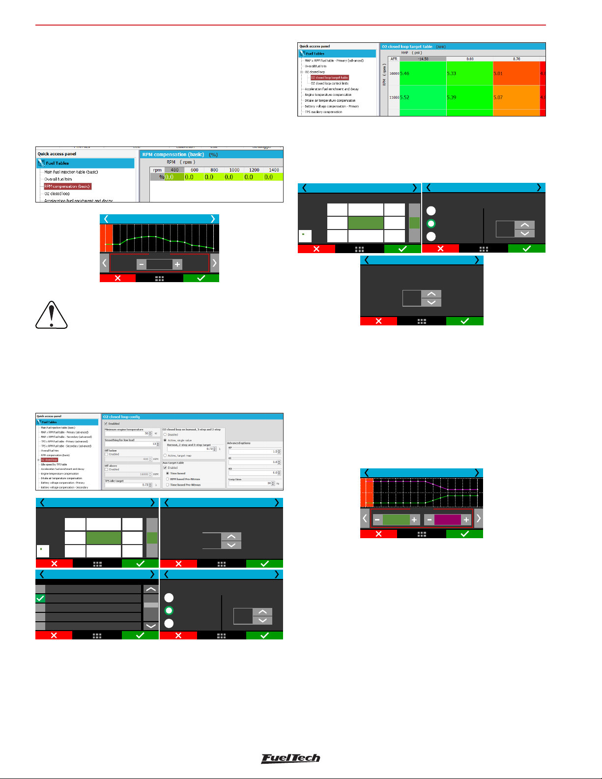
FT600
normally between 2000rpm and 4500rpm, but to know exactly the
rpm a dynamometer is required. Anyway, this compensation will be
performed, because, to keep a constant AFR, more fuel will be needed
at the maximum torque rpm.
With the main fuel table and the RPM compensation, the ECU generates
internally a injection time vs load vs RPM table.
RPM compensation
Fuel tables adjust
It is also possible to block the O2 closed loop under or above some
RPM limits. The “Lock below” parameter is used, i.e., on engines where
the O2 sensor is installed too close to the end of the exhaust, reading
free air below a certain RPM. The “Lock above” parameter is a limit to
disable the O2 closed loop and return to the open loop maps.
O2 cloed loop 4/9
0,80
0,70
0,80 0,88 0,75
4250
4000
0,90
0,88
1,00
1,00 0,80
RPM
3000
bar
0,90
+
λ
0,88
-
O2 closed loop 5/10
O2 closed loop on burnout, 3-step and 2-step
Disabled
Active, single value
Active, target map
Single value
0,75
λ
500 RPM
%
15
IMPORTANT
It is very important to check data continuity,
avoiding incoherent values that may produce
abrupt changes on the RPM graphic.
17.4 O2 Closed Loop
O2 closed loop reads O2 sensor and adds or removes fuel from the
main fuel table in order to reach the O2 target set up.
O2 cloed loop 4/9
bar
0,90
0,80
0,70
0,80 0,88 0,75
4250
4000
0,90
RPM
3000
0,88
Select O2 sensor position
O2 closed loop 4/11
General
Left bank
Right bank
Cylinder 1
Cylinder 2
1,00
1,00 0,80
0,88
+
λ
-
Low load smoothness is the speed control for low load situations like
idle speed, where the O2 closed loop must reduce the compensation
for O2 variations.
O2 closed loop 6/9
O2 closed loop on
idle by TPS
0,90
λ
O2 closed loop 5/10
O2 closed loop on burnout, 3-step and 2-step
Disabled
Active, single value
Active, target map
Single value
0,75
λ
O2 closed loop 6/9
O2 closed loop on
idle by TPS
0,90
λ
Next, is a 3D table of O2 closed loop targets versus RPM and MAP.
It has up to 16x16 cells that can be edited through the PC Software.
There is also an option to setup a different O2 target for burnout
mode, 3-step and 2-step. This target is a fixed value, no matter the
RPM or MAP pressure.
The next screen (6/9) is only shown when the idle is TPS based. Set
a target for idle condition (TPS=0%).
O2 closed loop 7/9
-10,0
%
-0,90 bar
10,0
%
Minimum Maximum
O2 closed loop control limits is a 16 points (8 columns and 2 lines)
table, totally editable, by TPS or MAP, which defines the actuation limits
of O2 closed loop, avoiding the control to remove or add too much
fuel in certain situations.
Auxiliary O2 closed loop:
Aux by time (2-step):
This feature allows the creation of a 16 points time based O2 target
table after the 2-step deactivation, which will overwrite the main O2
target table during the time setup on this auxiliary table. To trigger the
2-step, TPS must be above 50% or RPM must hit the 2-step rev limiter.
Engine temperature for control start is a temperature limit below
which the O2 closed loop stays disabled and assumes the open loop
fuel tables
60
Page 61
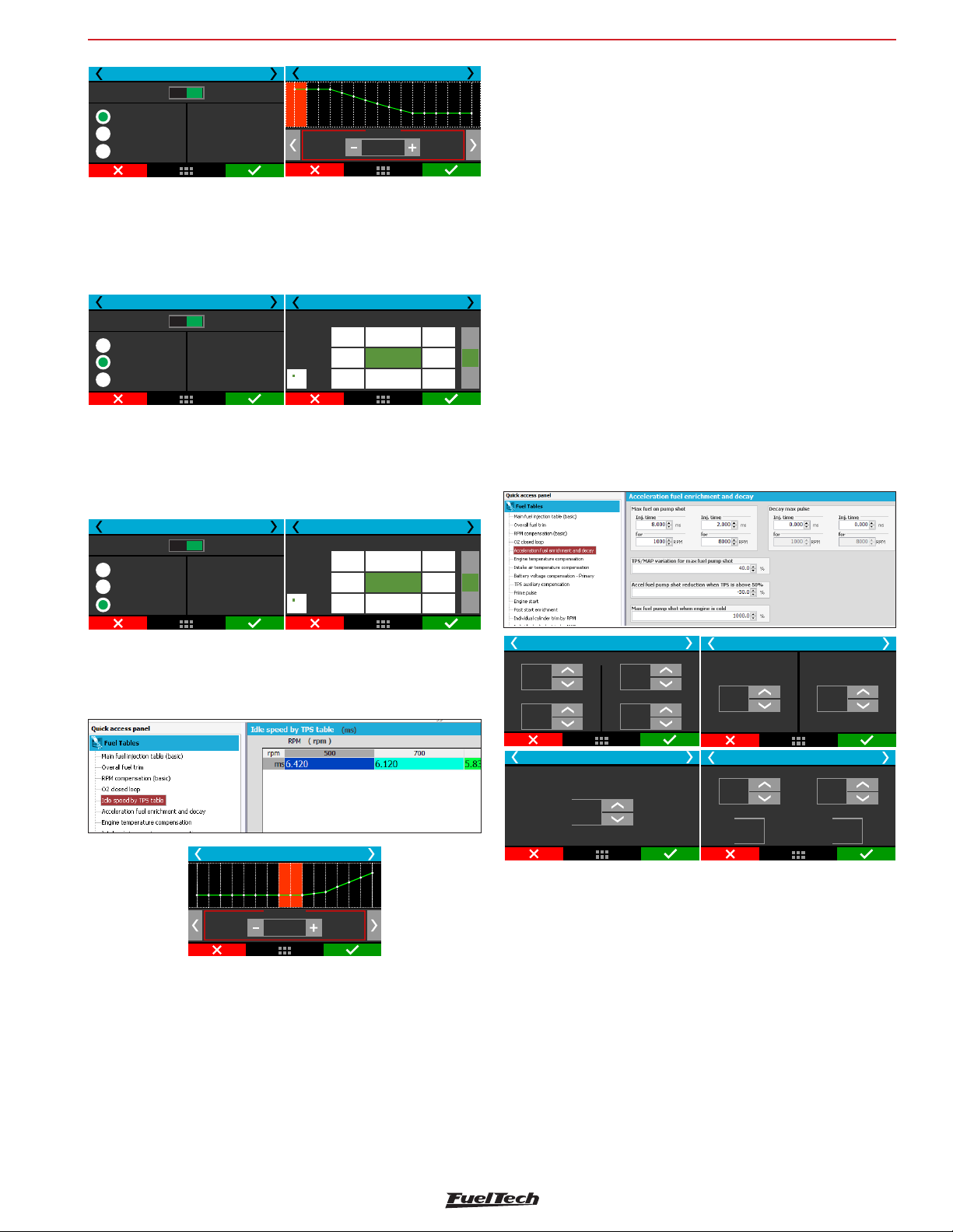
Fuel tables adjust
FT600
O2 closed loop 8/9
Disabled
Time based (2-step)
RPM based Pro-N.
Time based Pro-N.
Enabled
Auxiliary closed loop
Set time based lambda
target after 2-setp
release
O2 closed loop 9/9
0,00 s
λ
0,82
Aux Pro-Nitrous by RPM:
This feature allows the creation of a 16 points RPM based O2 target
table to each Pro-Nitrous stage, which will overwrite the main O2 target
table while the auxiliary control is on. This feature is only enabled when
all Pro-Nitrous requirements are fulfilled.
O2 closed loop 8/9
Disabled
Time based (2-step)
RPM based Pro-N.
Time based Pro-N.
Enabled
Auxiliary closed loop
Set based lambdaRPM
target to each
Pro-Nitrous stage
O2 closed loop 9/9
1
1
0,82 0,82 0,82
1000
2000
0,82
RPM
3000
0,82
Stages
2
0,82
0,82 0,82
0,82
32
3
+
λ
-
Aux Pro-Nitrous by time:
This feature is a 16 points time based O2 target table to each ProNitrous stage, which will overwrite the main O2 target table while the
auxiliary control is on. This feature is only enabled when all Pro-Nitrous
requirements are fulfilled.
TPS/MAP variation for maximum fuel pump shot: This configures the
MAP or TPS variation for which the max fuel pump will be used. Engines
equipped with small throttles usually need a higher TPS variation
to need max fuel pump. In this case, use higher TPS values on this
parameter (70-90%). For big diameter throttle bodies, a small TPS
variation is enough to demand max fuel pump (around 15%). The
TPS or MAP selection is done in the Engine Setup menu. If the TPS is
not present, MAP must be selected.
Accel fuel pump reduction above TPS 50%: due to reduced need
of fuel when the acceleration fuel pump occurs with the throttle already
opened above 50%, this parameter reduces the max fuel pump on
this condition. By standard, the ECU reduces 50% of the max pump
when it occurs above 50% of TPS.
Cold engine fuel pump enrichment: this is a simple increase on the
max fuel pump value when the engine is cold, especially necessary
on the first few minutes of engine operation.
Fuel decay on max pump: this is the injection time that will be
subtracted from the actual injection time during a sudden throttle
closure. With this, in a fast throttle closing, is possible to remove fuel
and have a more stable AFR during deceleration.
O2 closed loop 8/9
Disabled
Time based (2-step)
RPM based Pro-N.
Time based Pro-N.
Enabled
Auxiliary closed loop
Set based lambdaRPM
target to each
Pro-Nitrous stage
O2 closed loop 9/9
Stages
1
1
0,82 0,82 0,82
0,00
0,50
0,82
0,82
0,82
0,82 0,82
s
1,50
32
3
2
+
λ
0,82
-
17.5 Idle speed by TPS table
This menu is only available when the idle speed is set up by TPS. The
injection time is adjusted according to the engine RPM.
TPSidle fuel injection table
1250 RPM
ms
1,950
17.6 Acceleration fuel enrichment and decay
Acceleration enrichment is a fuel increase when the throttle is suddenly
opened.
Max fuel on pump: value added to the actual injection time
when a quick throttle variation is detected. There are two RPM and
injection time parameters to be set. With them, the FT600 creates
an acceleration fuel table that interpolates the values between these
two positions.
Accel fuel enrich and decay 1/4
Max fuel on pump
4,000
ms
to:
1000
RPM
Accel fuel enrich and decay 3/4
Cold engine fuel
pump enrichment
+350
%
100,0
ms
6300
RPM
to:
Accel fuel enrich and decay 2/4
TPSMAP/variation for
maximum fuel pump:
40,0
%
Accel fuel enrich and decay 4/4
Fuel decay on max pump
2,080
ms
to:
1000
RPM
Accel fuel pump reduction
above 50%:TPS
-50,0
%
0,930
ms
to:
6300
RPM
17.7 Engine temperature compensation
Engine temperature freatly influences the amount of fuel requested
by engine, especially in cars run with ethanol and methanol, when
it is possible to operate a cold engine as if it had already reached
normal temperatures.
This compensation is applied based on the engine temperature sensor,
which, in water-cooled cars, must be at the cylinder head reading the
water temperature, and in air-cooled engines, must be reading the
oil temperature.
Compensations based on engine temperature are only available when
the sensor is connected to the injection system.
61
Page 62
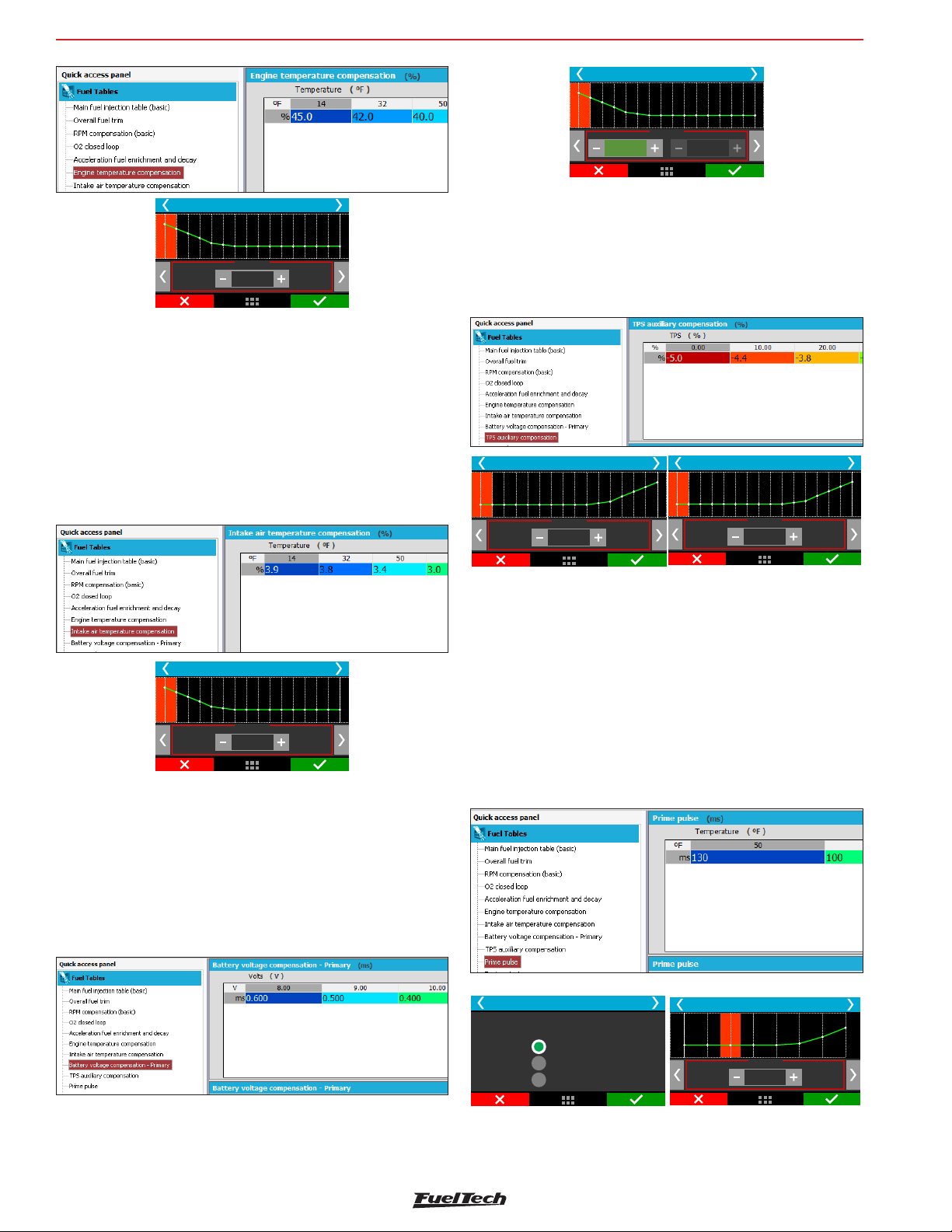
FT600
Battery voltage fuel compensation
8,0 V
Bank A Bank B
ms
2,345
0 000,
Fuel tables adjust
ms
Engine temp compensation
-20 °C
%
15
17.8 Intake air temperature compensation
This compensation is applied based on the air temperature sensor
placed in the intake manifold, and it is only available when the sensor
is connected to the injection system.
This compensation mode is used to automatically adapt the injection to
different temperatures of the air taken by the engine. In turbocharged
engines, it is of great importance, because when the system is
pressurized, the temperature rises immediately to very high numbers.
Intake Air Temp. compensation
17.10 MAP / TPS compensation
This table changes according to the main map configuration (MAP
or TPS). When the main fuel table is setup by MAP, this table is a
compensation by TPS. When the main fuel table is setup by TPS, this
compensation is by MAP.
MAP compensation
-0,90 bar
%
-15
TPS compensation
10 %
%
+15
17.11 Prime pulse
This feature improves the engine start by injecting fuel when any crank
trigger tooth is detected, just like OEM ECUs. Usually this table uses
injection times higher than the “engine start” parameter injection times.
-20 °C
%
-27
17.9 Battery voltage compensation
With lower battery voltages the injectors take a longer time to open
and to close. This table is used to compensate this variation.
Fuel injectors with a high flow rate usually operate with minimum
injection time at idle speed and are the ones most affected by a
battery voltage drop.
Select which fuel bank you want to use for prime pulse and setup its
table by engine temperature.
The injection time is related to engine temperature. The colder the
engine, the bigger the injection time.
Prime injection cranking pulse 1/2
Injectors banks for
prime pulse
Only bank A
Only bank B
Banks A and B
Prime injection cranking pulse 2/2
40 °C
ms
10
62
Page 63
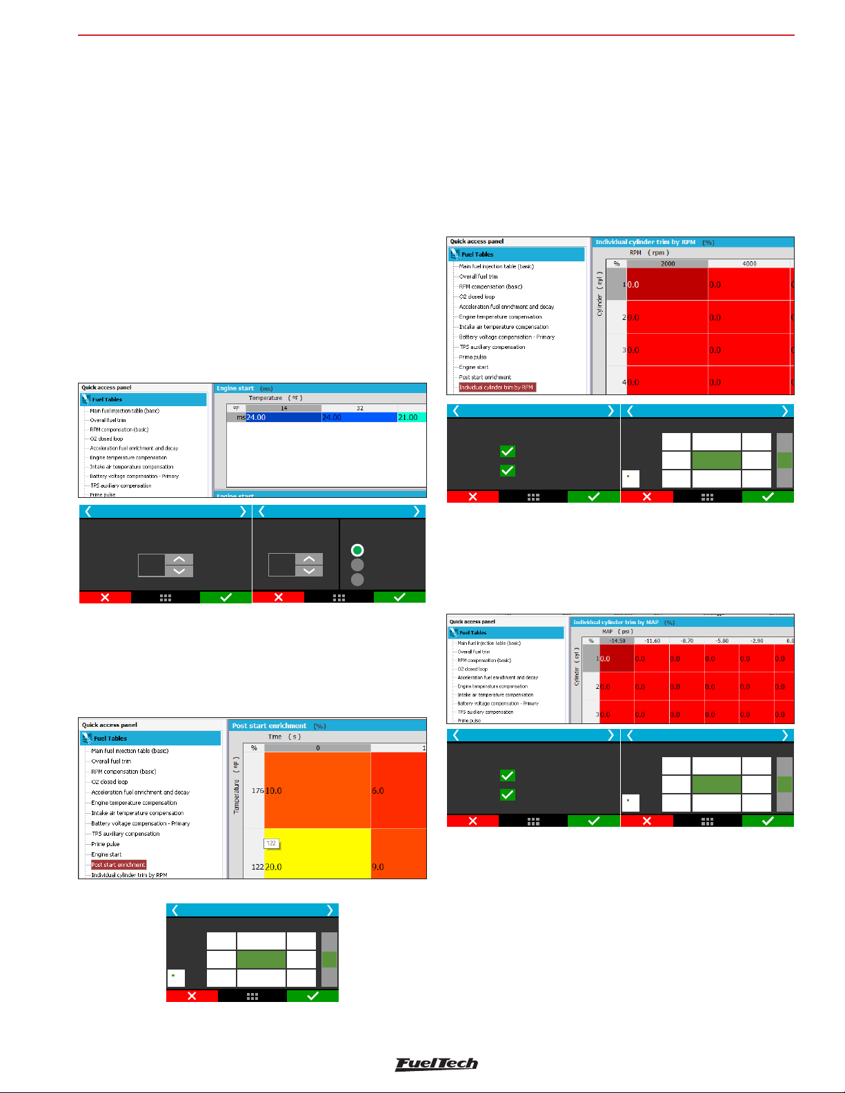
Fuel tables adjust
FT600
17.12 Engine start
This function is essential when starting the engine, as it needs a greater
injection pulse to initiate its operation, especially if the vehicle runs
on ethanol or methanol.
Whenever the RPM drops below 400rpm, the ECU applies start
injection pulses in addition to the idle speed value. This excess of
fuel prevents the engine from failing involuntarily, making it return to
idle speed. Be careful not to exaggerate on injection time, as it may
cause the engine to stall/flood easily.
The engine must always be turned off through the injection system.
Otherwise, if RPM drops below 400rpm and injection is turned on,
the system injects fuel that will not be burned and, therefore, will be
accumulated on the cylinder.
If the engine temperature sensor has not been installed, only the value
from start injection with cold engine is considered.
The bank B option will be only available if enabled on “Injection” menu
on “Engine Settings”
17.14 Individual cylinder trim
Set a compensation to each injectors output on a table that relates
engine RPM with individual cylinder trim compensation.
To use this compensation as a cylinder trim, the injectors have to be
wired with one output per injector.
This compensation usually brings minor power gains when correctly
used, so, the use of one O2 sensor per cylinder is highly recommended
Individual cylinder trim 1/2
Injectors for
individual cylinder trim
Primary
Secondary
Individual cylinder trim 2/2
Cylinders
1
1
-11,0-11,0-17,0
3000
4000
+1,0
+9,0
+3,0
+7,0 0,0
RPM
RPM
5000
3
3
2
2
+
%
-3,0
-
50
%
Engine Start 2/3
Injectors banks
on crank
Only bank A
Only bank B
Banks A and B
Engine Start 1/3
Ignition timing
on engine start
+,754
°
Disable cranking fuel
injection when is over:TPS
17.13 Post-start enrichment
This configuration is a table that relates engine temperature with time
in seconds. This parameter helps stabilizing engine RPM just after start,
improving the idle control especially under low temperature conditions.
Post-Start enrichment
1,00
10,0
+99+83 +35
30,0
+70
°C
60,0
+45
3,50
+35
+15
s
6,00
+
%
+15
0
-
17.15 Rotor compensation
Available only when controlling rotary engines, this is an individual
rotor fuel trim. This compensation usually brings minor power gains
when correctly used, so, the use of one O2 sensor per rotor is highly
recommended.
Individual cylinder trim 1/2
Injectors for
individual cylinder trim
Primary
Secondary
Individual cylinder trim 2/2
Cylinders
1
1
-11,0-11,0-17,0
3000
4000
+1,0
+9,0
+3,0
+7,0 0,0
RPM
RPM
5000
3
3
2
2
+
%
-3,0
-
63
Page 64
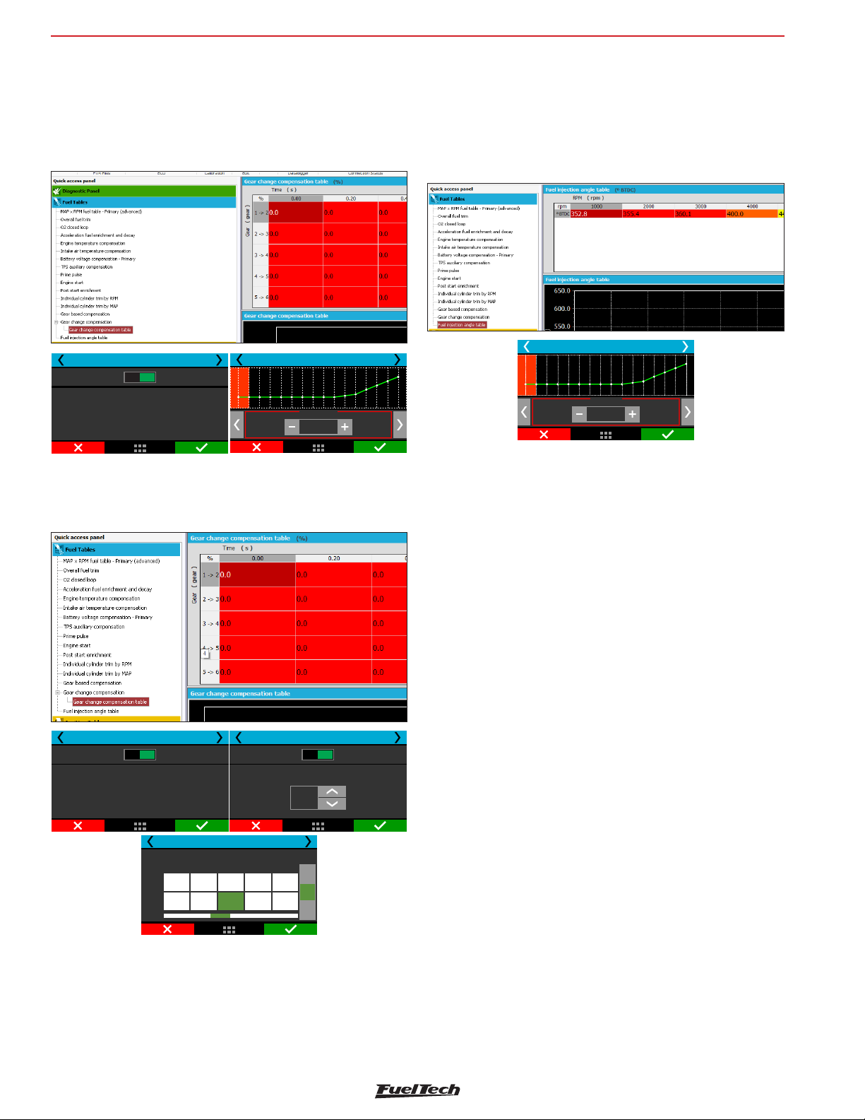
FT600
Fuel tables adjust
17.16 Gear based compensation
This option allows having a RPM based fuel compensation for each gear.
To enable this option, gear change detection must be enabled. It is
possible to set up to 6 compensation tables (6 gears).
Enrichment per gear 1/7
Disabled Enabled
Enables a fuel compensation
by map per gear. ThisRPM
function is used to ensure
safer O2 readings on higher gears.
Enrichment per gear 1 - 2/7
1000 RPM
%
+10.0
17.17 Gear shift fuel enrichment
17.18 Fuel injection phase angle table
This table changes the moment, during the engine cycle, where the
injectors open or close and is only available when the fuel injection
is being controlled in sequential mode. The injection phase angle is
the distance, in degrees BTDC from the ignition TDC (0°) until the
moment the injector opens or closes (according to what is selected).
Fuel injection phase angle table
500 RPM
°
250,0
This function enables fuel compensation when a gear shift is detected,
that allows building a time based enrichment table.
Gear shift fuel enrich. 1/7
Disabled Enabled
This feature adds fuel when a
gear shift is detected. Enrichment
adds the fuel amount set up here
for the time duration set here aswell.
NEW
Gear shift fuel enrich. 3/7
Fuel enrichment for gear shift: 1-2
1
Time
0,00
[s]
Percent
+0,0
[%]
0,05
+5,0
2
0,10
+4,5
Gear shift fuel enrich. 2/7
Disabled Enabled
Activate timing retard when is overTPS
80
%
53
4
+4,0
1,000,20
+0,0
+
%
-
64
Page 65
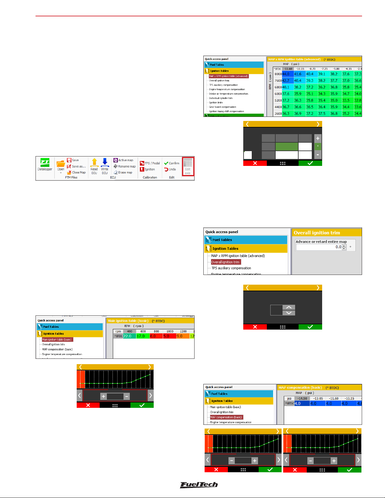
Ignition tables adjust
FT600
18. Ignition tables adjust
All timing tables can advance or retard timing. When a base map is
generated, all tables are filled with standard values, so, if you want
to use just the main timing table, you must zero fill all compensations
manually.
18.1 Main ignition table
The editing mode of this table is, by default, this table is displayed
in a 2D format. It is possible to change to a 3D table using the
FTManager software.
Through the software is also possible to edit the range interval of MAP,
TPS and engine RPM on the maps. This makes possible to increase the
detail level on specific ranges where a fine tuning is needed.
Basic mode 2D table
In this mode, the main ignition table is a 2D map that relates RPM and
timing from 400rpm to the max RPM.
Using an analogy, if you want an initial timing of 15º and final of 32º (as
you do on a distributor), you must enter 15º at 600rpm and 32º at the
maximum rpm, 8600rpm for example. The timing between maximum
and minimum RPM are interpolation of initial and final timing . If you
want to run a fixed timing, all cells must be filled with the same timing.
The default RPM steps are 200rpm until 3000rpm, and above this
rpm the steps are in 500rpm. The MAP, TPS or RPM steps can be
edited via FTManager
Main ignition table
bar
-0,80
-0,90
20000
19375
RPM
+50,0
+31,9
+31,1-30,0
18.2 Overall ignition trim
To apply a quick compensation to the entire ignition map, the Overall
Ignition Trim function may be used. It is only necessary to inform the
correction, negative or positive, and confirm by pressing the right
button. This correction will be added to or subtracted from the entire
ignition table based on RPM
Remember that the timing applied will only be the same as the main
table if all the compensations are zero.
The rpm breakpoints can be changed up to 32 cells, allowing a fine
tuning.
Ignition Tables Adjust
400 RPM
º
+18,75
Advanced mode 3D table
In this mode, the main ignition table is a 3D map that relates RPM x
MAP x ignition timing. As well as the basic mode, the MAP range is
from -14.5psi up to de desired pressure. When the main timing table
is by TPS, the table is from 0 to 100% in 10% steps.
Overallignition trim
Advance or retard
entire map
-6,01
°
18.3 MAP/TPS compensation
This table changes according to the main map configuration (MAP
or TPS). When the main ignition table is setup by MAP, this table is a
compensation by TPS. When the main ignition table is setup by TPS,
this compensation is by MAP.
MAP compensation
-0,90 bar
º
15,7
TPS compensation
0 %
º
2,9
65
Page 66
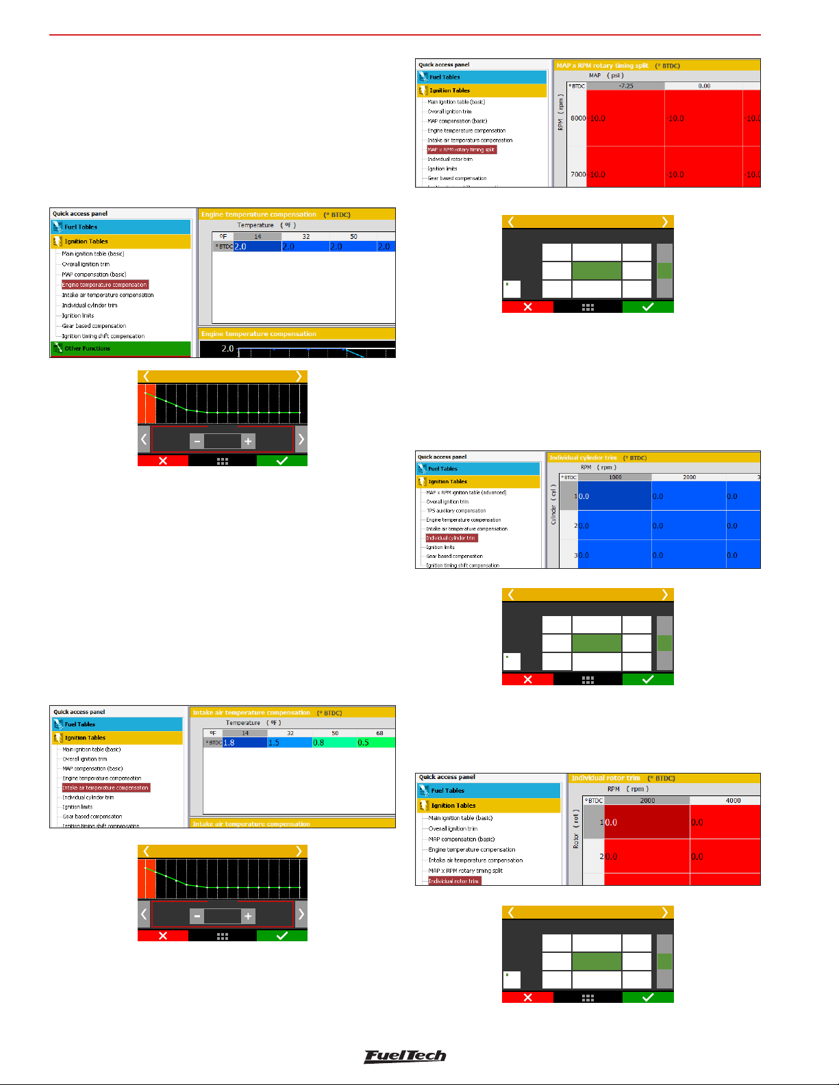
FT600
18.4 Engine temperature compensation
This map represents a compensation on the advance or retard angle
applied to the main RPM map based on engine temperature variation.
It is a very important feature and it brings significant improvement on
drivability, especially while operating cold engines, when advanced
ignition timing is necessary in order to have a correct response from
the engine. It is also essential for engine protection, as it retards the
ignition timing when the engine reaches high temperatures.
Rotary timing split
bar
-0,70
-30,0
-29,9
-0,1
-15,5
+15,5
4250
4000
RPM
3000
18.7 Individual cylinder trim
-0,30
0,0
Ignition tables adjust
0,00
+0,1
+
°
+29,9
+30,0
-
Engine temp. compensation
-10 °C
º
+3,0
18.5 Intake air temperature compensation
This map represents a timing compensation applied to the main RPM
timing map based on intake air temperature variation.
It is beneficial, because the colder the air entering the combustion
chamber, the denser it is, and the greater the possible ignition advance
is.
But when temperatures are very high (especially on turbocharged
engines), the ignition timing must be retarded to protect the engine.
Set a timing compensation to each ignition output on a table that
relates engine RPM with individual cylinder trim compensation. The
timing compensation is done individually to each cylinder according
to the engine RPM and it comes from the flow differences, heating
dissipation capacity or even cylinder position.
Individual cylinder trim
Cylinders
4250
4000
RPM
3000
-30,0
-29,9
-0,1
1
-15,5
+15,5
3
2
+0,1
+
°
+29,9
0
+30,0
-
18.8 Rotor compensation
Available only when controlling Rotary engines, this is an individual
rotor ignition trim.
Intake Air Temp. compensation
-10 °C
º
5,0
18.6 Rotary timing split
This menu is only shown when controlling Rotary engines. This is the
timing split between Leading and Trailing spark plugs.
66
4250
4000
RPM
3000
Rotary timing split
-0,70
-30,0
-29,9
-0,1
bar
-0,30
-15,5
0,0
+15,5
0,00
+0,1
+29,9
+30,0
+
°
-
Page 67
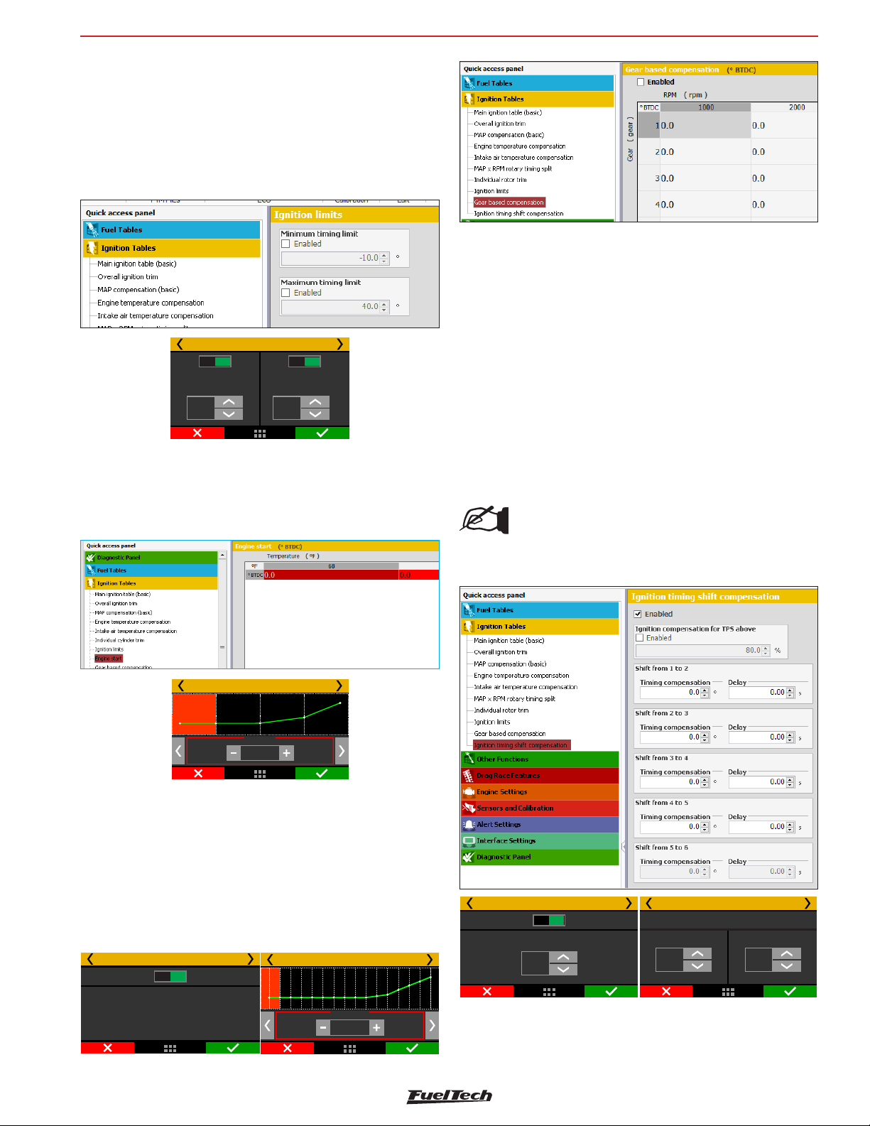
Ignition tables adjust
18.9 Timing limits
This menu is used to configure the maximum and minimum ignition
timing limits, so the engine won’t run in any situation with too much
retard or advanced ignition timing. No other function will be able to
apply timing beyond these limits. This is a safety feature to prevent an
inappropriate timing, considering all the functions that may enable a
timing compensation (mainly drag race time based features).
FT600
18.12 Gear shift compensation
This function allows advancing or retarding the timing after a gear
shift (upshift).
Timing limits
Disab.
Minimum timing
+10,0
°
Enab.
Disab.
Maximum timing
+35,5
Enab.
°
18.10 Engine Start
This is an ignition advance vs engine temperature table. Calibrate the
ignition advance for each temperature site.
Engine Start
-20 °C
°
+7,75
You can enable a TPS condition so the retard can happen.
In the example, there will be a 5º timing retard. The ramp return
time is the retard total time, which will be gradually re-established.
In other words, after shift gear, timing will be retarded 5º, 0,25s the
retard will be 2.5º and 0,50s after the shift there will be no gear shift
compensation.
To enable this option, gear change detection must be enabled. It is
possible to set up to 5 compensation tables (6 gears).
NOTE:
To use this function it’s necessary to have gear
detection activated.
18.11 Gear compensation
This compensation allows advancing or retarding the ignition timing
according to the engaged gear. This table applies the compensation
in the main ignition table according to engaged gear and RPM.
To enable this option, gear change detection must be enabled. It is
possible to set up to 6 compensation tables (6 gears).
Gear compensation 1/7
Disabled Enabled
Enables a timing compensation
map per gear. This functions
allows the control os power
levels per gear through ignition
timing, improving traction and
driability
Gear compensation 1 - 2/7
1000 RPM
º
-5,50
Gear shift compensation 2/7
Disabled Enabled
Activate timing retard when is over:TPS
80
%
Gear shift compensation 3/7
Timing ramp for gear shift 1 - 2
Timing retard
-5,00
°
Ramp return time
0,50
s
67
Page 68
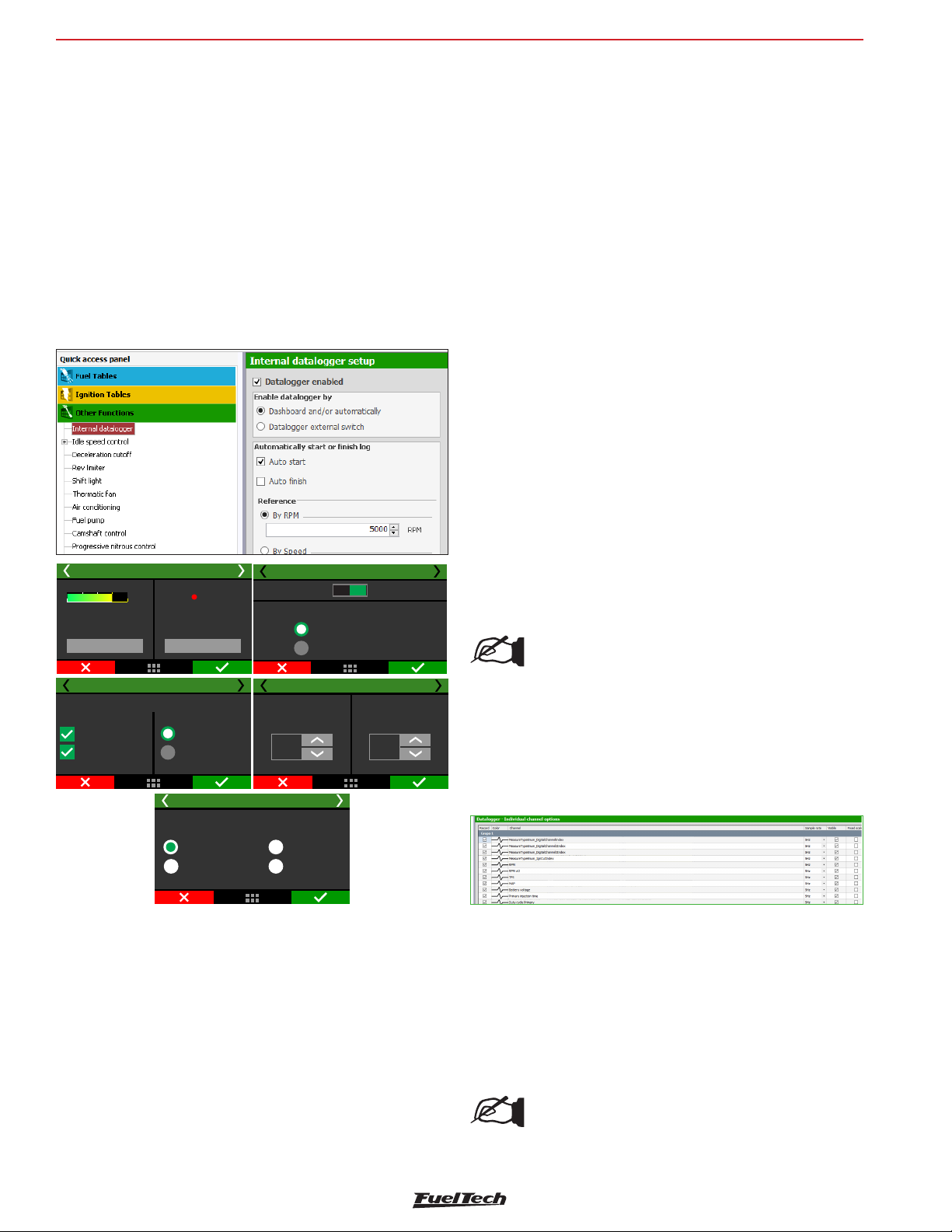
FT600
Others functions
19. Other functions
This menu allows the adjustment of all functions that modify the
operation of auxiliary outputs and compensations of idle speed, etc.
19.1 Internal datalogger
This function is used to log all the engine data read by FuelTech ECU.
The Internal Datalogger can record up to 256 channels like: injection
time (banks A and B), injectors duty cycle (banks A and B), timing,
engine rpm, auxiliary output status, TPS, coolant and air temperature,
oil and fuel pressure, O2 sensor, two-step button, MAP sensor, camshaft
position sensor and battery voltage.
Log download and data analysis are done through the computer and
FTManager Software.
Log start and stop
The internal datalogger start and stop trigger can be set up by RPM
signal or by a button on the ECU dashboard.
When selecting “RPM Signal”, the log will be started only when the
programmed RPM is reached. If a button on the dashboard is preferred,
select it on the internal datalogger. After that, go to “Interface settings”
menu and set up the datalogger button on a spot under “Dashboard
setup.
Log is automatically stopped when memory is full, ECU is turned off
or the button is pressed.
Via FTManager software, the log can be started or finished through
the “Start log” and “Stop log” in the tool bar. The “Erase memory” will
clear all the logs in the FT600 memory.
Sampling rate
The sample rate defines the log quality. Higher sample rates create more
detailed logs, however, the logging time available will be shortened.
For competition vehicles, especially drag racing, it is recommended to
use a high sample rate to have high detail level on the log.
The lower the sample rate, the more “square” will be the graph and
less detailed. On the other, the higher the sample rate, the more
detailed the log.
Internal datalogger 1/3
Memory status
Allfiles will be lost
by pressing the button
Erase memory
Auto start.
Auto finish.
75
WARNING:
%
below.
Internal datalogger 4/6
Automaticaly start or finish log
Datalogger status
REC
To manually start
or stop recording use
the button below
Start Log
By RPM
By wheel speed
or driveshaft
Internal datalogger 6/6
25Hz
50Hz
Sampling rate
Internal datalogger 2/6
Disabled Enabled
Datalogger activation
Dashboard and /or automaticaly
Datalogger external switch
Internal datalogger 5/6
Start above:
Finish below:
5000
RPM
100Hz
200Hz
Delay to finish log
2,00
s
Datalogger enabled
Select if the datalogger is enabled or not and set the start/finish mode.
Through dashboard a touchscreen button will start or stop the
recording. Through external switch an white input must be wired to
an on/off switch to enable the recording. While the input is grounded
the datalogger will be recording.
It is possible to choose two modes for the Internal Datalogger:
Basic: All channels are logged with the same sampling rate.
Advanced: allows the user to select the channels that will be logged
and their sampling rate. Functions and sensors added after setting the
internal datalogger on advanced mode will be automatically logged
with the default sampling rate, but this can be changed if desired.
Automatically erase memory at 100% usage
If this option is checked, the memory will be erased when it reaches
100% capacity, this means older logs will be permanently erased and
the recording of new logs will be possible.
NOTE:
During the erasing process it’s not possible to record
a log.
Individual channel options
In this menu it is possible to setup each channel individually about line
color, if it will be visible or not, its scale and, when in the advanced
mode, its sampling rate.
Internal datalogger status
At the Dashboard Screen of the ECU, a round icon is shown besides
engine RPM. This icon indicates the Internal Datalogger status.
• Internal datalogger stopped: grey “Data” button
• Recording: green “Data” button, blinking light red icon with the
word REC
• Memory full: red “Data” button with the word FULL
NOTE:
When memory is full, connect the ECU to the PC and
download the data thought FTManager Software.
68
Page 69
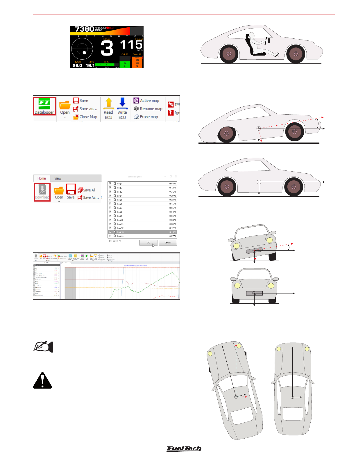
Other functions
FT600
Log download
The log download must be through FTManager. Connect the FT600
to the computer with the USB cable
Open the FTManager, and click on the Datalogger icon. The FTManager
Datalogger will open. To download, click on the Download icon and
a window will pop up showing all logs saved on the ECU. Select the
files and click ok.
The datalog software will open. Use the mouse to browse the graph
and check the values on the left panel.
G-Force acceleration: records the vehicle’s acceleration force.
G-Force braking: records the vehicle’s braking force.
Pitch angle: records the vehicle’s pitch angle.
Pitch rate: records the vehicle’s pitch rate.
α
Lateral G-Force: registers the vehicle’s lateral force.
Roll: registers the vehicle’s roll angle.
19.2 Accelerometer and gyroscope
FT600 has an internal 9-axis accelerometer which provides the
following data:
NOTE:
See section 15:19 for the accelerometer
calibration.
ATTENTION:
In order for the accelerometer and gyroscope
to work properly and have correct readings, a
calibration of the sensor is required. The FT600
should be installed as vertical as possible, with
a maximum inclination of 45 °. The connectors
must face the front of the vehicle. The screen
must face the rear of the vehicle.
β
Speed under acceleration: calculates the speed based on the
vehicle’s acceleration.
Distance under acceleration: measures the traveled distance based
on the vehicle’s acceleration.
69
Page 70
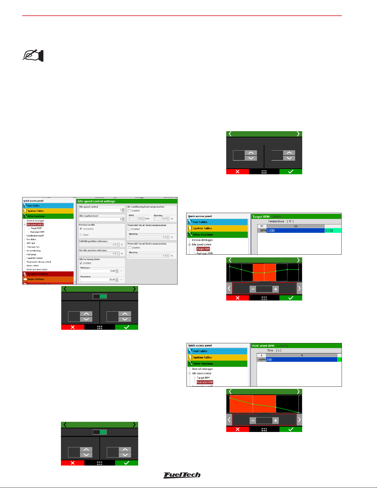
FT600
Others functions
Direction: records the calculated position in degrees based on the
moment the vehicle launched.
NOTE:
The features: speed under acceleration, distance
under acceleration, roll angle and pitch angle are
calculated only after a valid launch (when with the
2-step activated the engine hits TPS higher than 50%
or the 2-step rev limiter).
19.3 Idle speed control
This FT600 can control idle speed through electronic throttle, step
motor, PWM valve and by timing.
To enable the idle speed control by electronic throttle, it is needed to
setup the menu “Electronic throttle” under “Engine setup” menu. After
that, you can follow this menu to setup idle parameters.
Actuator reaction level: this parameter is the aggressiveness that
the timing and the actuator will be changed of position in order to
control a RPM fall. The higher this number, the more aggressive is the
reaction of the control.
High reaction levels may lead the idle speed to be unstable.
Idle speed by timing
This control uses a target RPM for idle speed and works by advancing
and retarding the engine timing to keep the engine running near the
specified RPM.
As the FT600 idle speed control has an advanced integration with
the idle speed by timing control, this one stays always enabled when
any other kind of idle speed control is selected. By doing this, the
idle speed actuator is always kept in a position where the idle speed
by timing control can set the timing away from the maximum and
minimum timing positions.
Maximum and minimum timing limits: these values are the limits
for advance and retard when ECU is controlling the idle by timing.
Idle speed control settings 2/7
Idle ignition timing limits
Maximum
+25,00
°
-5,00
°
Minimum
Actuator position
This parameter will be only available when the position on idle is set
as fixed. This table relates the actuator position in function of the
engine temperature.
Idle speed control settings 1/9
Advanced ()PC
Idle control
speed
3
Basic
Idle control
reaction level
5
Position on idle
Automatic: in this mode, idle actuator is automatically opened and
closed by the ECU in order to make the engine idle near the target RPM.
Fixed: in this option, idle actuator assumes a fixed position, set up
later according to engine temperature.
ETC reference position: this parameter is the actuator position
when the engine is turned off or cranking. It is also used as a stable
reference during the automatic idle speed control. Setup a value that’s
enough for a cold start of the engine. Start with a value around 4%
for electronic throttle and 30% for step motor.
Idle speed control settings 2/9
Automatic
Standard reference
openning (cold)
3,0
%
Fixed
Standard reference
openning (hot)
6,0
%
Idle speed control settings 5/7
95 °C
%
16,0
Post-start position
This parameter will be only available when the position on idle is set
as fixed. The table controls the actuator opening after the engine start.
The table is an actuator position vs time. After the time slip, the position
is defined by the actuator position table based on engine temperature.
Idle speed control settings 6/7
2 s
%
+2,5
RPM for idle speed
This table tells the ECU the target RPM the idle control will assume,
according to engine temperature. On intermediate temperature ranges,
target RPM is automatically interpolated.
70
Page 71
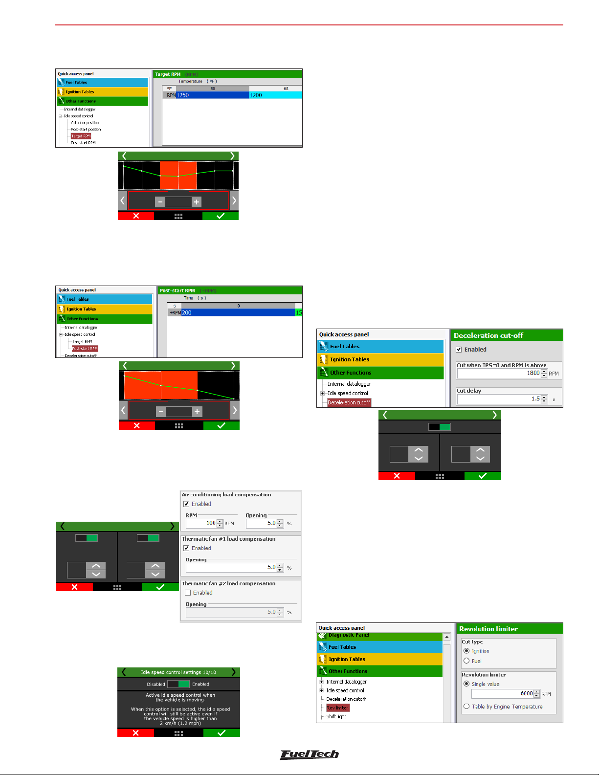
Others functions
FT600
When “Position on idle” is set to “fixed” this table represents the
actuator position X engine temperature.
Idle speed control settings 5/7
95 °C
RPM
1000
Post-Start position
This parameter is a RPM increase (or % of increase in the actuator
position for fixed idle position). The table shows the actuator position
according to time post engine start.
19.4 Deceleration cut-off
The purpose of Deceleration cut-off is to improve fuel economy when
the engine is at 0% throttle situations.
This aids in the deceleration of the vehicle by making use of engine
braking while driving in traffic. This function is valuable to the reduction
of fuel consumption
On a circuit racing or autocross vehicle is utilizing heavy braking going
into a turn, it is necessary that it has a quick and clean response from
the engine upon re-opening the throttle.
Deceleration cut-off will aid in dynamic braking from the engine as
well as overall fuel economy.
A standard RPM of 2000rpm is recommended. Setting a very low
RPM may cause the engine to turn off involuntarily during deceleration
The “Cut-off Delay for TPS=0%” parameter is the time (in seconds)
delay before fuel is actually cut-off after releasing the throttle. Such
delay exists to prevent the engine from instantly becoming lean when
the throttle is released. It also rapidly cools the combustion chamber
without being excessive, and avoids situations in which the cut-off
might oscillate, especially when the throttle is lightly pressed. A
standard delay of 0.5s is suggested.
Such delay exists to prevent the engine from instantly becoming lean
when the throttle is released.
Idle speed control settings 6/7
2 s
RPM
+500
Compensation by load: used to compensate actuator position when
suddenly loads (like AC or fan) are added to engine and can affect
idle. It is possible to set an target RPM compensation when the AC is
on and fuel/actuator opening compensation for AC and fans.
Idle speed control settings 9/9
Disab.
Thermatic Fan 1
compensation
10,5
%
Enab.
Disab.
Thermatic Fan 2
10,5
Enab.
compensation
%
Idle speed control on movement: when this option is checked the
idle speed control will turn on when the TPS percentage is 0% and
the engine RPM is 700 rpm above the set target.
Deceleration cut-off
Disabled
Cut when =0TPS
and above:
2500
RPM
Enabled
Cut delay
0,5
s
19.5 Revolution limiter
This function is very important for engine protection, limiting the RPM
with two different options of cut-off:
Fuel Injection: the fuel injection is cut-off instantly, as the ignition is
still operating. It is a very smooth and clean cut-off. Recommended
only for naturally aspirated engines, it is the standard setting in vehicles
with original injection systems.
Ignition: the engine ignition is cut-off when the configured RPM
is reached. It is recommended for high-power engines, especially
turbocharged ones, being the most efficient and safe option.
71
Page 72
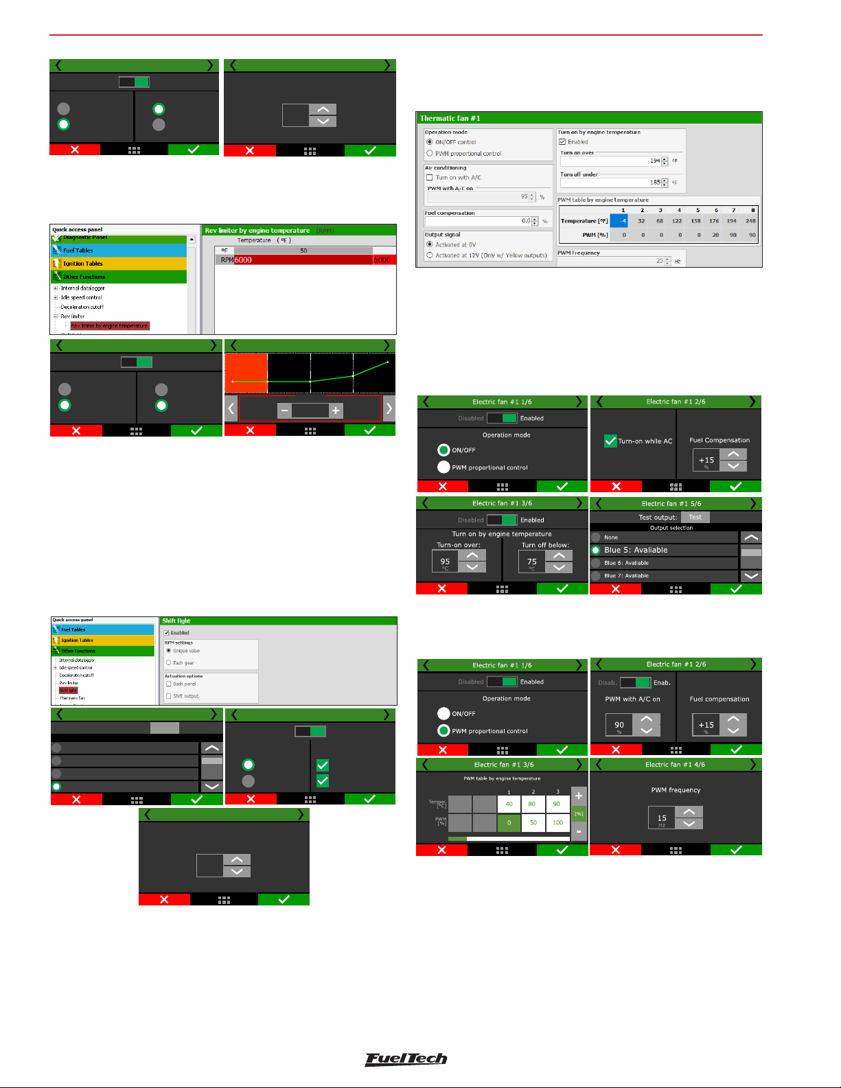
FT600
Others functions
Limitador de rotação /12
Desativado Ativado
Ignição
Injeção
Valor único
Tabela
Revolution limiter 2/2
Rev limiter
7000
RPM
Rev limiter by engine temperature
When the option “table by engine temperature” is selected, it’s possible
to set different rev limiters according to engine temperature
Revolution limiter 1/2
Disabled Enabled
Ignition
Fuel injection
Single value
Tabel
Revolution limiter 2/2
-20 °C
RPM
2000
ON/OFF: The thermatic fan will switch on/off depending on the
temperatures that are set. There’s also the option to turn on the
thermatic fan when the A/C is on, to do so select “turn on with A/C”
There’s an option that allows one of the fans to be activated when
A/C is turned on. As these fans may draw considerable load, a fuel
compensation is also available.
To test the fan output, just click on the “Test output” button. If it doesn’t
work, check the install or test another output.
Through FTManager, the output configuration is done in the “Sensors
and calibration” menu - Outputs.
19.6 Shift Light
When the engine reaches the RPM set in this parameter, the screen
will display a blinking message (“SHIFT”) indicating that gear must
be shifted.
To switch an external shift light, it is necessary to configure an
auxiliary output at the “Input and Output Setup” menu. If no auxiliary
output has been configured as Shift Light, the message “Output not
configured!” will be displayed. Even so, it is possible to set the Shift
Light RPM on the screen
Shift light 1/3
Test output:
Output selection
None
Blue 5: Avaliable
Blue 6: Avaliable
Blue 7: Avaliable
Test
Shift light 3/3
Turn on shift light
with RPM above
RPM settings
Shift light 2/3
Disabled Enabled
Single value
Each gear
Output options
Dashboard
Output pin
PWM proportional control: The thermatic fan will be controlled
by a solid state relay via PWM control, this creates a very linear and
progressive control of the engine temperature.
8000
RPM
19.7 Thermatic Fan #1
There are to two ways to set up the control of the thermatic fan #1,
either by an on/off command or a PWM proportional control.
72
Page 73
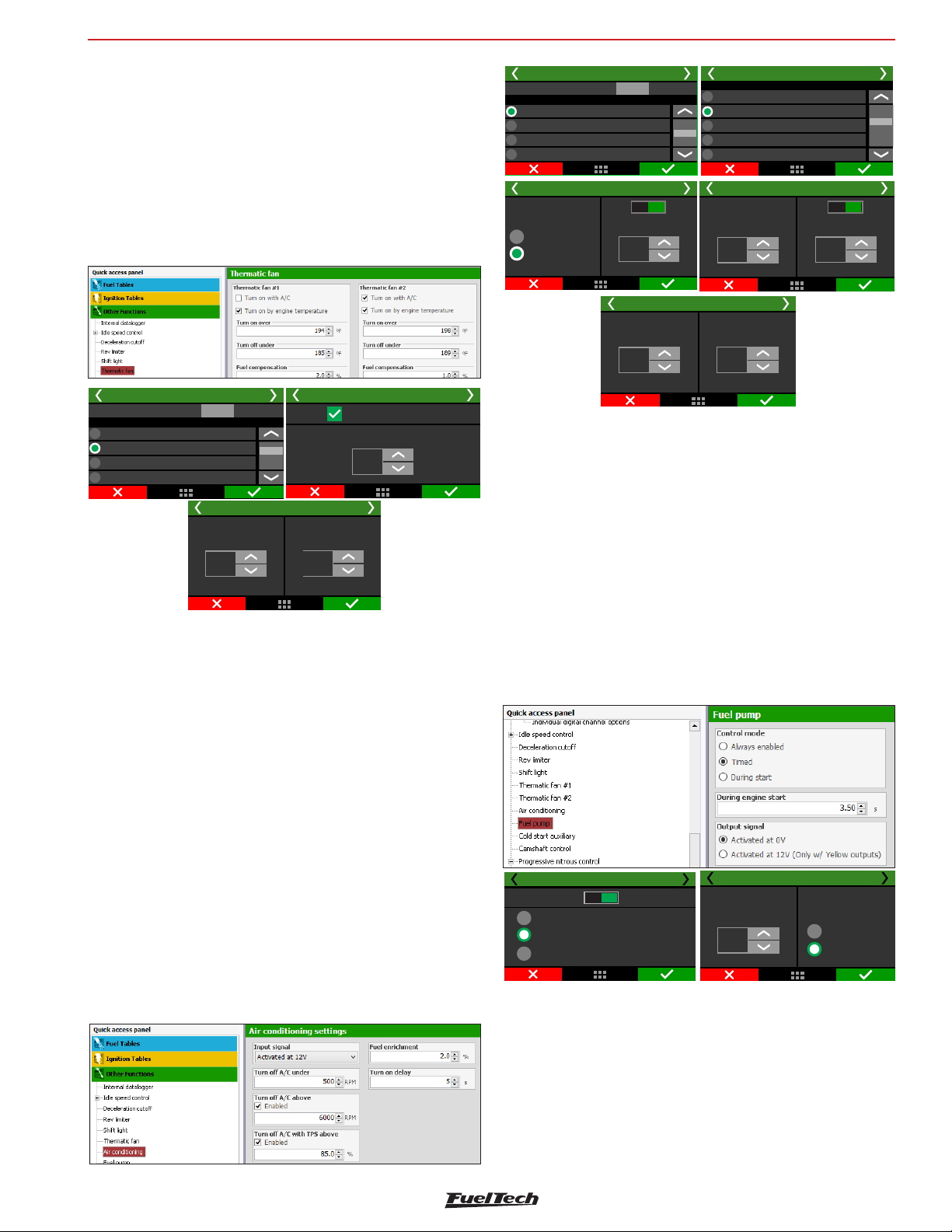
Others functions
FT600
19.8 Thermatic Fan #2
This FT600 can control up to two cooling fans on different temperatures.
There’s an option that allows one of the fans to be activated when
A/C is turned on. As these fans may draw considerable load, a fuel
compensation is also available.
To test the fan output, just click on the “Test output” button. If it doesn’t
work, check the install or test another output.
Through FTManager, the output configuration is done in the “Sensors
and calibration” menu - Outputs.
Turn-on while AC
Turn off below:
+75
°C
Electric fan #1 2/3
Fuel compensation
+15
%
Electric fan #1 1/3
Test output:
Blue 7: Fuel pump
Blue 8: Available
Gray 5: Available
Gray 6: Available
Output selection
Test
Turn-on over:
+95
°C
Electric fan #1 3/3
19.9 Air conditioning
To control air conditioning through FT600, first you have to setup an
output to control the A/C relay. Then, setup the input that will receive
signal from the A/C button on the car dashboard. Check chapter 13
for more information.
Air conditioning 1/5
Test output:
Gray 7: Available
Gray 8: Available
Yellow 1: Available
Yellow 2: Available
Air conditioning 3/5
Positive
Negative
Output selection
Disab. Enab.
Test
Turn-off A/C
with above:TPS
95,0
%
Fuel
enrichment
+10,0
%
Input selection
Turn-off A/C under:
Air conditioning 5/5
Air conditioning 2/5
None
White 1: Available
White 2: Available
White 3: Air temperature
White 4: Pedal #1
Air conditioning 4/5
700
RPM
Turn-on delay
3
s
Disab. Enab.
Turn-off A/C above:
7000
RPM
19.10 Fuel pump
This output activates the fuel pump relay through lowside (0V) or
highside (12V).
You can choose from the following options:
Always enabled (the output is permanently activated while the
ignition switch is on)
Timed (when the ignition switch is turned on, the output is activated
for a defined activation time, afterwards the output is deactived. When
engine speed signal is received, the ECU reactivates the output.).
During start (when the output is activated while it’s below the
starting engine speed).
It’s required to use a relay that supports the necessary current for the
fuel pump. Through the FTManager software, the output configuration
is done through the menu “Sensors and calibration” and then “Outputs”
The turn on delay will happen in 3 different situations:
- When starting the engine with the AC button turned on, the turn on
delay will start to count after the RPM for engine start is overcome.
In this case, the reference is engine start, not the moment when the
AC button is switched on.
- When turning off and then turning on the AC button, the turn on
delay will count from the moment the AC button is turned off. If the
time between turning off and then turning on is bigger the turn on
delay set, the AC will be immediately activated.
- When the engine RPM is below the minimum RPM the turn off is
immediate. The delay will count from the moment the RPM is below
the minimum RPM. To turn on again, the delay will start to count when
the engine RPM is 50RPM higher then the minimum.
Fuel pump 3/3
Output Signal
Activated at 0V
S
Activated at 12V
Disabled
Always enabled
Timed
During start
Fuel Pump 2/3
Enabled
Activation time
3,50
19.11 Cold start auxiliary
This feature is very useful for cold starts on methanol and alcohol
engines using a gasoline injection auxiliary kit. The table shows the
auxiliary injector time versus temperatures
The ECU will activate the output according to the time set on the table
once it detects the first tooth from engine RPM on every engine start.
The cold start auxiliary is disabled when cranking the engine with the
accelerator pressed with TPS above the value set in the parameter
“Disable injection on engine start with TPS above” in the “Injection”
73
Page 74
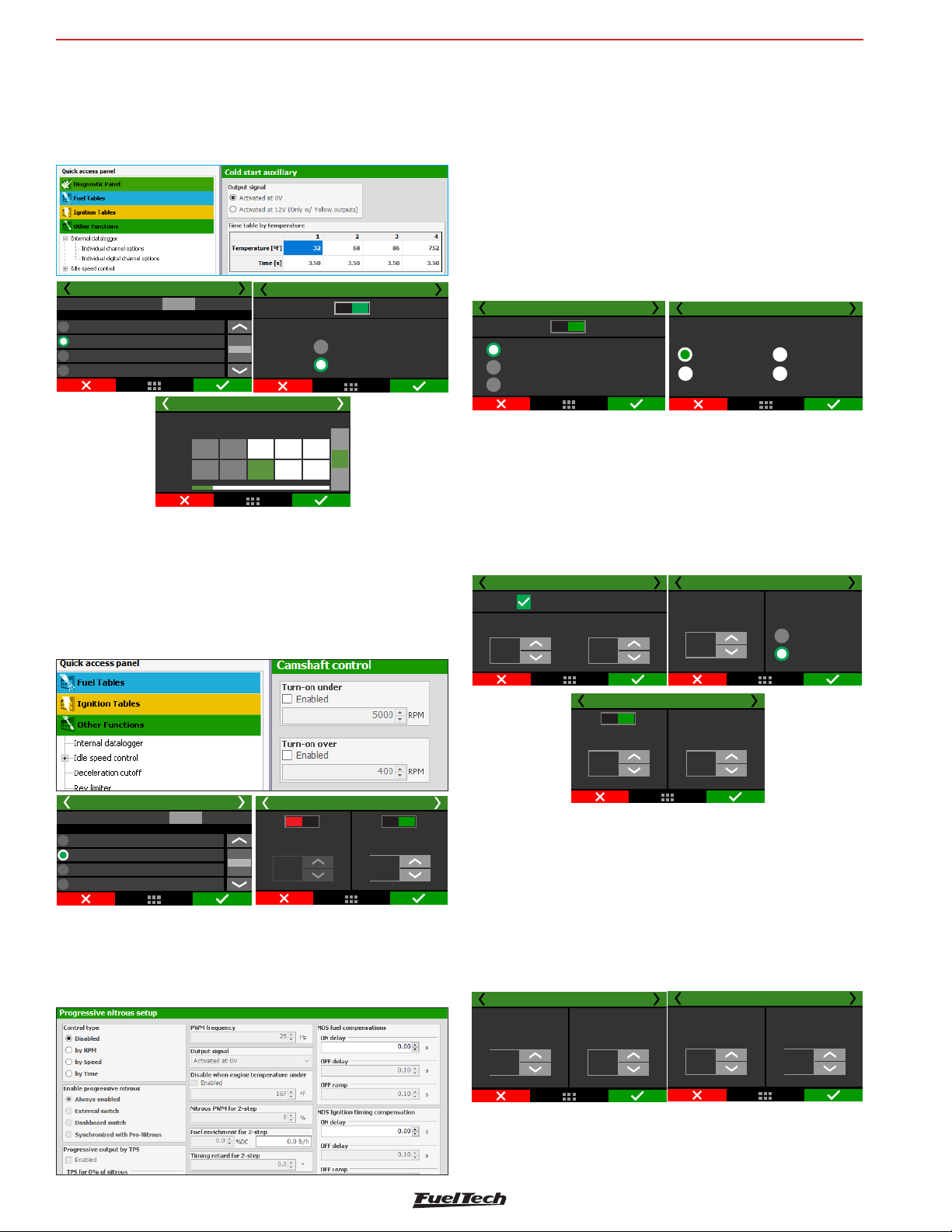
FT600
PWM frequency
15
Hz
Activated at 12V
Activated at 0V
Output Signal
Progressive nitrous control 6/20
Others functions
menu, under “Engine settings”.
Output signal: Activation through 0V in the blue or gray outputs. The
yellow outputs have the possibility to activate the outputs through 12V.
Time versus temperature curve: This table is composed of a pulse
in seconds of the cold start injector depending on engine temperature.
Cold start auxiliary 1/3
None
Blue 5 Cold start auxiliary:
Blue 6Avaliable:
Blue 7Avaliable:
Test :output
Output selection
Test
Temp Motor
Cold start auxiliary 3/3
[]°C
Time
[S]
Time table by temperature
1
-20,0
3,5
Cold start auxiliary 2/3
Disabled
3
2
20,00,0
3,5
3,5
Enabled
Output signal
Activated at 0V
Activated at 12V
+
[S]
-
19.12 Camshaft control
This function allows the control of a variable valve timing control
system (or a drag racing 2-gear automatic system). Select the output
used to control the camshaft solenoid, and then, inform the RPM that
the solenoid must be turned on. Only on/off camshaft systems can
be controlled.
Select an auxiliary output as “Progressive nitrous output” and how
the control will be performed: by time (after 2-step), by rpm or by
wheel speed.
Also, select the enable mode:
• Always enabled;
• External switch: select a white input. When the input is grounded
the progressive nitrous will be enabled;
• Dashboard switch: a touchscreen button must be configured
to enable or disabled the progressive nitrous;
• Synchronized with Pro-Nitrous: the progressive nitrous control
will activate when the Pro-Nitrous (Drag race features menu)
conditions are met;
Progressive nitrous control 2/20
Disabled Enabled
RPM based control
Time based control
Speed based control
Progressive nitrous control 3/20
Enable progressive nitrous
Always enabled
Progressive
nitrous arm switch
Dashboard switch
Synchronized
with Pro-Nitrous
The first parameter to be configured is the TPS opening percentage,
above which the injection of nitrous will be activated.
The next parameter is the percentage of fuel enrichment for 100%
nitrous.
After this, set the PWM output frequency and the output signal. To
regular solenoids, use between 25 and 30Hz, big shot solenoids use
50Hz. The next screen will show the engine temp protection, where
you can define a minimum engine temperature for progressive nitrous.
Progressive nitrous control 5/20
Progressive output
TPS for 0%
of nitrous:
10
%
TPS for 100%
of nitrous:
95
%
Camshaft control 1/2
Test output:
Grey 8: Fuel pump
Yellow 1: Available
Yellow 2: Available
Yellow 3: Available
Output selection
Test
Disab. Enab. Disab. Enab.
1500
RPM
Camshaft control 2/2
Turn-on over:Turn-on under:
7000
RPM
19.13 Progressive nitrous control
This auxiliary output configuration gives access to setting the ratio
for the fuel-nitrous mixture (or nitrous only) through pulse-width
modulation (PWM) sent to the solenoids.
Progressive nitrous control 7/20
Disab. Enad.
D
isable Nitrous when
engine temperature under:
75
°C
Nitrous PWM
for 2-step
0
%
The fuel enrichment for 2-step is a fuel compensation when the
2-step is enabled. The timing retard for 2-step is a compensation
applied to the timing configured in the 2-step function. The minimum
and maximum RPM is a RPM window and work as a safety feature,
so the progressive nitrous will only active if the engine rpm is inside
the window. The total time to return PWM control is a delay ramp to
reactivate the progressive nitrous when it is disabled by any safety
features or switch. This ramp avoids the progressive nitrous to return
in a big shot, helping the traction on pedaling.
Progressive nitrous control 8/20
Fuel enrichment
for 2-step
+75,0
%DC
Timing retard
for 2-step
-5,0
°
Progressive nitrous control 9/20
Minimum RPM
for activation
0
RPM
Maximum RPM
for activation
8000
RPM
74
Page 75
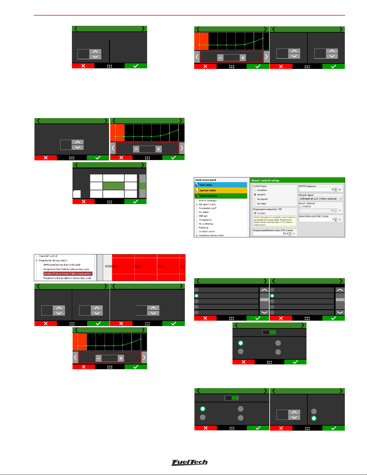
Others functions
FT600
Progressive nitrous control 10/20
Total time to return PWM control
0,00
s
Progressive nitrous has 3 safety
parameters: TPS, RPM and Switch
When nitrous is turned off and
then turned on again, it is
recommended this return to be
progressive, reaching the
maximum programmed PWM
only after the time set here.
Next is the nitrous injection map based on RPM. The higher the
percentage configured in this map, the higher the amount of nitrous
(or nitrous + fuel) injected
The maximum RPM is the same chosen on “Fuel Injection Setup.
With the FTManager you can edit axis and add or remove cells.
When using 2 injector banks the fuel enrichment will happen on both.
Progressive nitrous control 13/20
Delay to start fuel
compensation
0,00
S
7000
6000
RPM
5000
Nitrous: Enrichment 15/20
-0,90
+5 +45
+1
0,000
+0
Fuel enrichment by %PWM 14/20
bar
-0,70
-0,80
+25
+25
+15
+10+20
+50,0
+
%
-
0%
%DC
+75 lb/h
Nitrous: Ignition retard 19/20
2500 RPM
°
-15,9
Nitrous: Ignition retard 20/20
Time to deactivate timing compensations
0,00
Delay
S
0,00
S
Ramp
In the end, there are the OFF delay and the OFF ramp and are used
to keep the engine safe, avoiding an immediate timing advance that
could damage the engine.
19.14 Generic duty cycle output
This feature allows the control, through PWM, of a solenoid valve that
manages the wastegate valve, therefore regulating the boost pressure.
Through an external button, you can activate the Boost+ function
(optional use), which is an instant increase in the boost %DC while
the Burton is turned on.
FuelTech recommends using a 3-way button N75 solenoid.
For more information about its installation, see chapter 13.8 in this
manual.
The ON delay for NOS fuel compensation avoids the extra fuel to get
earlier than the NOS in the cylinder, very common when the fogger
is far from the injectors.
The Progressive fuel table by nitrous duty cycle and the Auxiliary fuel
enrichment table compensation are related to the percentage of fuel
added according to %DC of nitrous or engine load/rpm.
Nitrous: Enrichment 16/20
Time to deactivate fuel compensations
0,00
Delay
S
Ramp
0,00
S
Timing retard by %PWM 18/20
10%
-15,9
Nitrous: Enrichment 17/20
Delay to start timing
°
compensation
0,00
S
After the end of nitrous shot, normally is necessary to keep the
compensations on for a few tenths of seconds, since the intake is full
of nitrous that will be consumed by the engine. The OFF ramp makes
the compensation ends smoothly.
The delay to start the timing compensation has the same purpose of
fuel compensation, the time nitrous takes to reach the cylinder.
The Progressive timing table by nitrous duty cycle and Auxiliary timing
retard compensation are related to the timing retard (always negative
values) according to the %DC of nitrous and engine load/rpm.
The first parameter is the output which will drive the boost solenoid.
Select among the available outputs. After this, select the Boost+ input,
if necessary.
In the FTManager, this setting is done in the “Sensors and calibration”,
then “Inputs” and “Outputs”.
Generic duty cycle output 92/
Input selection
None
White 1: avaliable
White 2: avaliable
White 3: Oilpressure
White 4: 2-step
Generic duty cycle output 3/9
Disabled Enalbed
Control by RPM
Control by time
Generic duty cycle output 92/
Input selection
None
White 1: avaliable
White 2: avaliable
White 3: Oilpressure
White 4: 2-step
Control by spped
Control by MAP
The next screen allows to quickly enable or disable the function and
choose the control mode: by rpm, by time (after 2-step) or by speed.
Generic duty cycle output 3/9
Disabled Enalbed
Control by RPM
Control by time
Control by spped
Control by MAP
Generic duty cycle output 69/
PWM frequency
15
Hz
Output Signal
Activated at 0V
Activated at 12V
75
Page 76
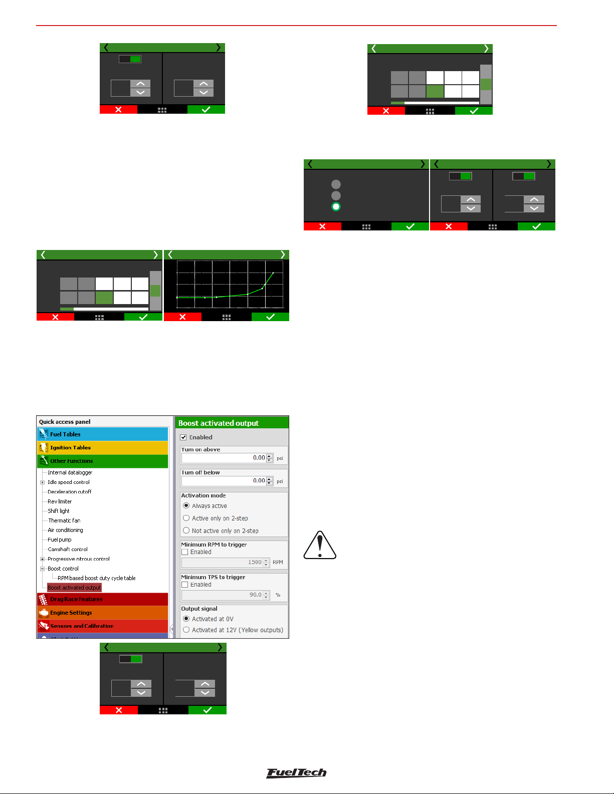
FT600
Others functions
Generic duty cycle output 79/
Disab. Enab.
Generic duty cycle
increase button:
20
%
2-step
duty cycle
0
%
“Programmed boost when TPS is over” is the minimum TPS value to
activate the boost solenoid. When the progressive output is selected,
boost output is progressive to boost table, starting at 10% to the
“Programmed boost when TPS is over” value.
• The recommended frequency for most PWM 3-way valve is 20Hz.
The output signal depends on the solenoid installation. Check
Chapter 13.8 for further information.
• Select if you want to use the Boost+ button.
The boost duty cycle for 2-step is the boost level when the 2-step is
on, which overrides any other boost table.
Generic duty cycle output 8/9
RPM based boost duty cycle table
Revs
[]RPM
PWM
[%]
1
400
50
0
+
800600
[%]
100
-
3
2
Generic duty cycle output 9/9
100
75
50
25
0
400
1500
3000 4500 6000 90007500
Once your parameters are setup in there will be boost duty cycle table
by rpm, speed or time. The boost by time starts after the 2-step release.
19.15 Boost activated output
This function is used to activate an auxiliary output according to MAP
readings.
Generic duty cycle output 8/9
RPM based boost duty cycle table
Revs
[]RPM
PWM
[%]
1
400
0
3
2
50
+
800600
[%]
100
-
Select the output signal sent when it is activated. The only outputs
capable of switching 12V are the yellow.
Define the vaccum/boost range to trigger the output.
Boost activated output 4/5
Always active
Active only on 2-step
Not active only on 2-step
Boost activated outputs 5/5
Disab. Enab.
Minimum RPMto
trigger
7000
RPM
Disab. Enab.
Minimum TPSto
trigger
90,0
%
There are 3 different activation modes: “always active”, “active only
on 2-step” or “Not active only on 2-step”. This means that even if
the vacuum/boost conditions are met, the activation mode condition
must be respected.
As safety features, minimum TPS and RPM values can be set, so the
output will not activate if one or more conditions are not met.
19.16 Tachometer output
By default, the tach output is configured on the grey #8 wire, but can
be set on one of the yellow wires also.
If one of these outputs is not available, the blue #1 to #8 and grey #1
to #7 can also be used, but an external 12V pull-up with a 1K resistor.
In the FTManager, this setup is at “Sensors and calibration” - “Outputs”
Generic duty cycle output 79/
Disab. Enab.
Generic duty cycle
increase button:
20
%
2-step
duty cycle
0
%
Select an available output to trigger a relay or any other external device.
In the FTManager, this setup is at “Sensors and calibration” - “Outputs”
19.17 Wastegate boost pressure control
The active control function of the wastegate valve pressure is used
for a more precise control of turbo pressure in street, circuit and,
mostly, drag race cars. The control can be performed by time after
2-step, by gear and engine RPM, by gear elapsed time, by a single
target or by engine RPM, besides specific targets for 2-step, 3-step
and burnout mode.
IMPORTANT:
- The pressure controlled by BoostController is
the pressure at the top of the wastegate valve.
- You can set the maximum MAP pressure and
maximum MAP pressure on 2-step.
- When the BoostController is off the target is
zero, and each time the read pressure, for any reason,
exceeds 1.45psi the decrease solenoid is activated.
Installation diagram
1 - Decrease solenoid/injector trigger – connected to the blue or
yellow output;
2 - Decrease solenoid;
3 - Increase solenoid/injector trigger – connected to the blue or
yellow output;
4 - Increase solenoid;
5 - 12V from relay;
76
Page 77
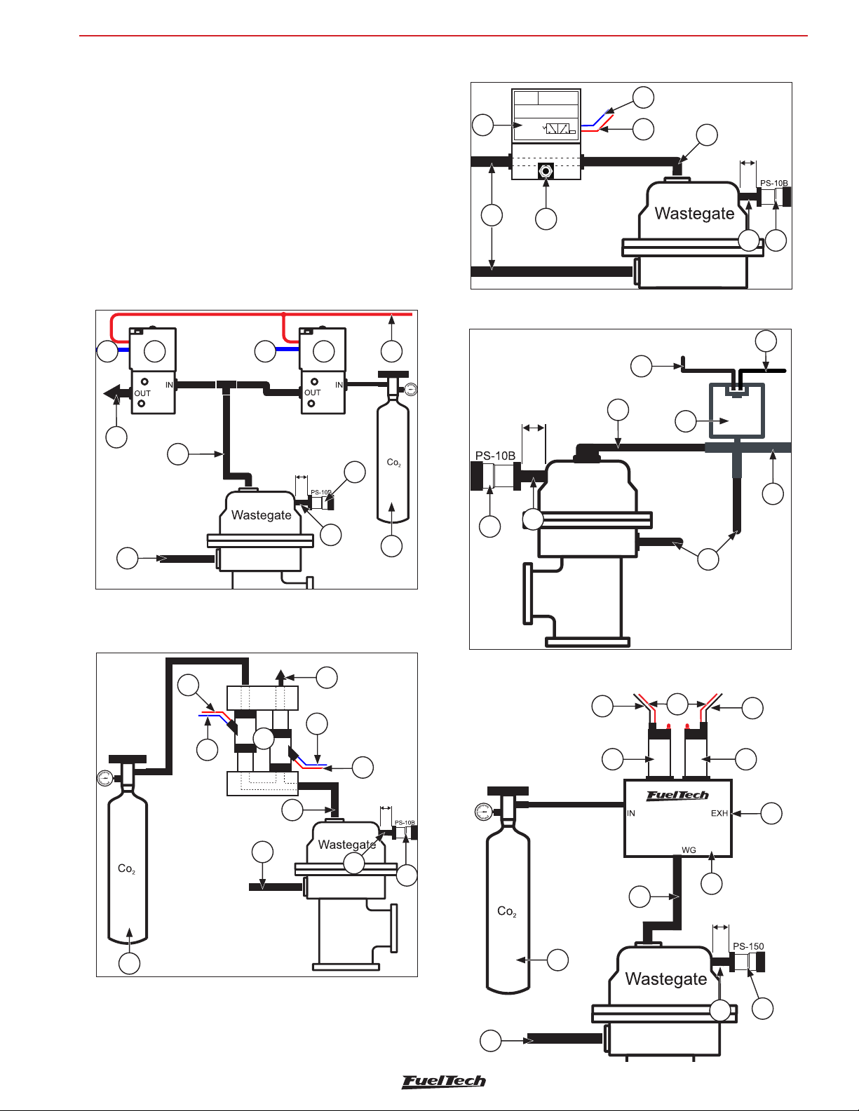
Others functions
1
2
3
1
2
3
3
FT600
6 - Intake or CO2 bottle;
7 - Pressure sensor;
8 - Pressure sensor hose;
9 - Intake;
10 - Free air;
11 - Injectors block;
12 - 3 way Valve or N75;
13 - Actuation of 3 way valve or N75;
14 - Control pressure Wastegate;
15 - FT dual valve block;
16 - Connection to second Wastegate or must be blocked;
Diagram with regular solenoids
1 2 3 4 5
10
14
Max
30cm
7
Diagram with 3 way Valve
12
9
10
Diagram with N75 Valve
Max
30cm
Wastegate
14
13
13
5
14
Max
30cm
8 7
5
N75
12
2
1
10
9
Diagram with injectors block
5
3
6
11
9
14
8
6
7
8
9
10
Diagram with FT dual valve block
3
5
1
1
5
Max
30cm
4
2
10
8
7
15
14
Max
30cm
6
8
7
9
77
Page 78
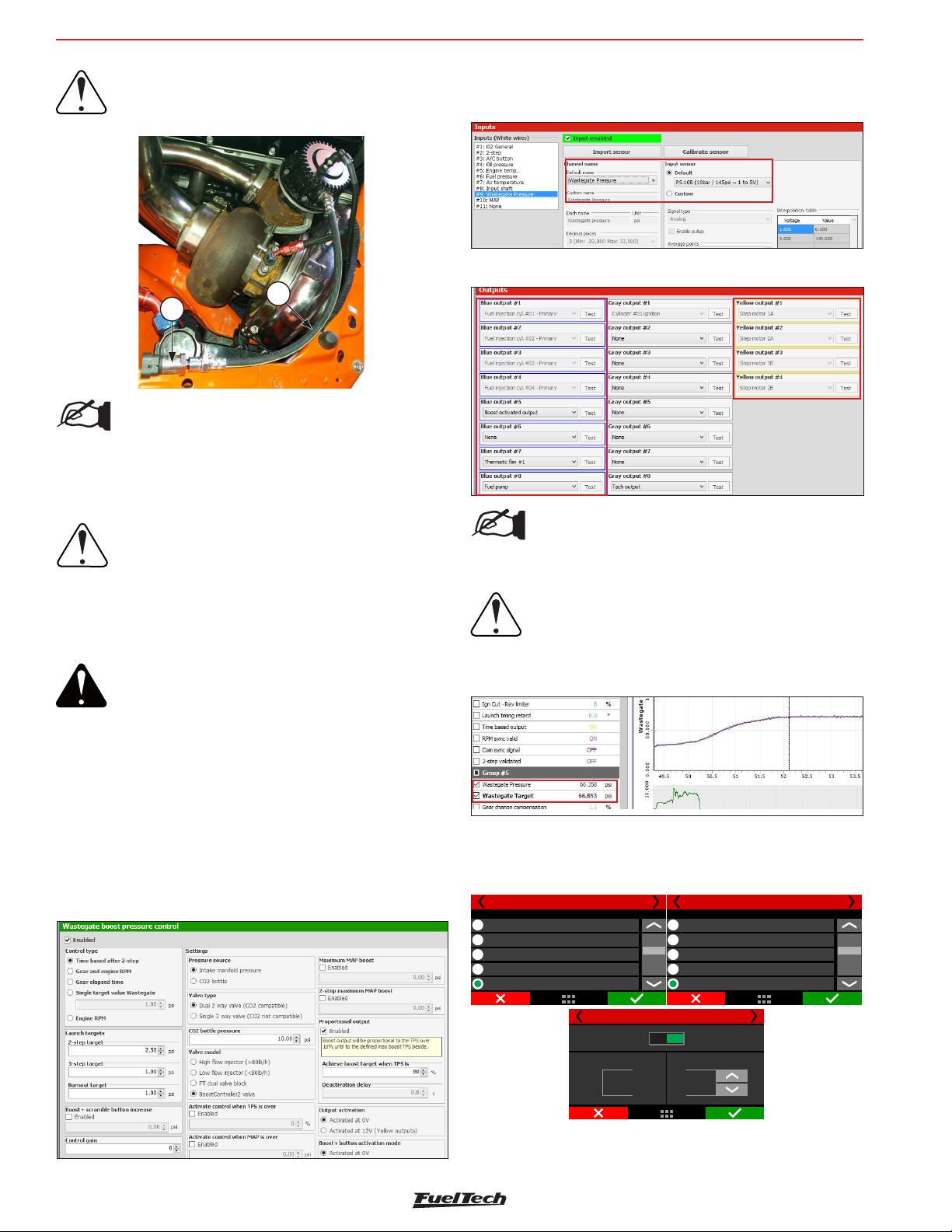
FT600
Others functions
IMPORTANT:
Use a PS150 pressure sensor connected to any white
input. Setup as “Wastegate pressure”.
8
7
NOTE:
The pressure sensor (7) must be connected to the top
of the wastegate with a hose (8) with a maximum
length of 1ft. It prevents damage to the pressure
sensor caused by vibration.
IMPORTANT:
- The pressure sensor must be installed on
an exclusive line, and not shared with any other
connection, to avoid reading errors.
- For the correct operation of the system, use
only FuelTech PS sensors line: PS-150, PS-300, etc.
WARNING:
The boostcontroller test (when set as time based
after 2-step) will only work with the engine
turned off.
To test this feature with the engine running, a
valid launch is required (when with the 2-step
activated the engine hits TPS higher than 50%
or the 2-step rev limiter).
Set the input for the pressure sensor as PS-10B, PS-20B, PS-150
and PS-300 or BoostController2 MAP. In FTManager access the menu
“sensors and calibration/inputs”.
Set the outputs of the increase and decrease solenoid valves.
NOTE:
It is recommended to use the yellow or blue outputs
for connecting the solenoids.
IMPORTANT:
Avoid using different color outputs for solenoids. Use
two yellow outputs or two blue outputs.
In datalogger you can configure the channels for monitoring
BoostController pressure.
FTManager setting
Through FTManager you can make all settings required for the
operation the BoostController.
78
FT600 Input setting
In the “Sensors and calibration” menu select the “Wastegate pressure”,
after this set the associated input and the sensor type used.
Input select
None
White 1: Avaliable
White 2: Two Step
White3: Avaliable
White 4: Avaliable
Wastegate pressure 1/XX
Sensor type
Wastegate pressure 3/XX
Input value
Reading
3,50
bar bar
Wastegate pressure 2/xx
MAP Boost (6bar/87psi- 0 a 5V)
PS10A (10bar/145psi- 1 a 5V)
PS10B (10bar/145psi- 1 a 5V)
PS20B (20bar/290psi- 1 a 5V)
PS150 (10,2bar/150psi - 0,5 a 4,5V)
Output value
Sensor offset
+0,36
bar
Page 79
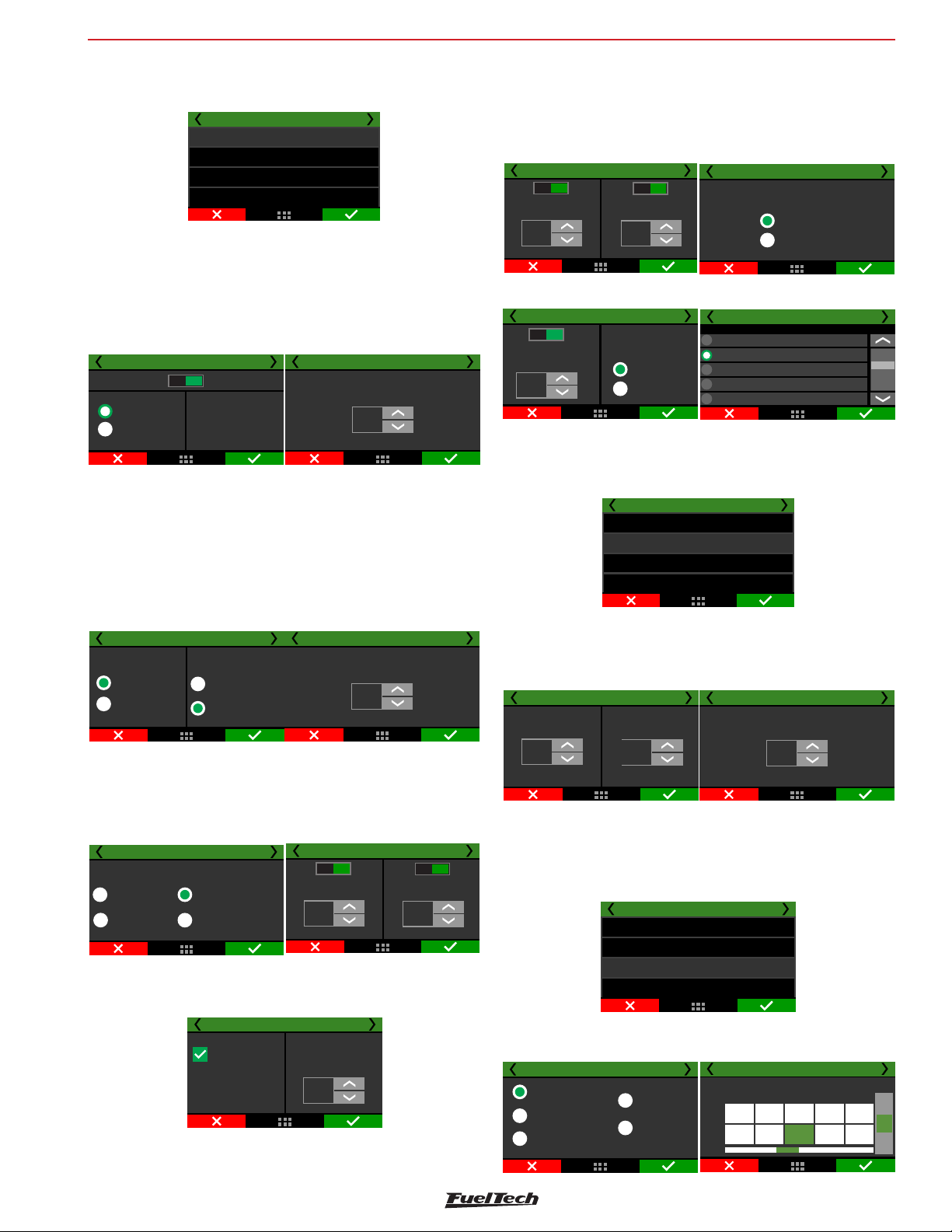
Others functions
FT600
FT600 setting
In this menu, you can setup the BoostController basic functions.
Wastegate boost pressure control
General config
Lauch targets
Main targets
Overall trim
Basic: You can access all control settings through the FT600 screen.
Control gain: Adjust the control gain according to the valve response.
If it is taking to achieve the target it is necessary to increase the gain,
if it overshoots the target it is necessary to reduce this value.
Advanced (PC): Some settings are available only in FTManager
software.
General config 1/13
Disabled Enabled
Basic
Advanced (PC)
All control options
enabled
Pressure source: When configuring your boost controller, it is
necessary to inform the ECU where your pressure will be sourced
from; intake manifold, or C02 bottle.
When using a bottle, an industrial pressure regulator is required,
limiting the line pressure according to the desired configuration.
Two manometers must be used, one before the regulator indicating
the pressure in the bottle and the other after the regulator showing
pressure in the line.
General config 3/13
Pressure source
Intake manifold
pressure
Co2 bottle
Valve mode
Dual 2 way valve
(Co2 compatible)
Single 3 way valve
(Co2 not compatible)
Valve model: You can choose which valve type will be used, high or
low flow injectors, FuelTech 2 valve block or BoostController2 solenoid.
You can set a minimum value for BoostController activation by TPS
and MAP.
General config /513
High flow injector
(>80lb/h)
Low flow injector
(<80lb/h)
Valve model
FT dual valve block
BoostController2 valve
Disab. Enab.
Proportional output: from 10% TPS the output is proportional to
the map. The programmed pressure is reached when the TPS reaches
the value set.
General config 7/13
Progressive output
when this option is
enabled, the output is
progressive to table.
Programed value will be
reached for the TPS
setup beside.
MAP maximum pressure and MAP maximum pressure on 2-step:
Allow to set a MAP maximum pressure during 2-step and out of the
General config 2/13
General config 4/13
Co2 bottle pressure
10.0
General config 6/13
Activate boost when
TPS is over
10
%
Programmed value
when TPS is:
80
%
Control gain
5
PSI
Disab. Enab.
Activate boost when
MAP is over
0.0
psi
2-step. This function will not adjust the MAP pressure according to
a target and will make the pressure bounces around the target. This
maximum pressure must be used only as a safety feature to prevent
overboost.
Output activation: the output can be triggered at 0V or 12V
General config 8/13
Disab. Enab.
Maximum MAP
pressure
3,00
psi
Disab. Enab.
2-Step maximum
MAP pressure
3,00
psi
General config 9/13
Output activation
Activated at 0V
Activated as 12V
Boost+ button: Increases boost pressure while is switched on.
General config 12/13
Disab Enab
Boost+ Scramble
Button increase:
12.0
psi
Button mode
Activated at 12V
Activated at 0V
General config 13/13
Boost+ button input selection
None
White 1: Avaliable
White 2: Avaliable
White 3: Avaliable
White 4: Avaliable
Launch targets
Defines the target pressure at the top of the valve in 2-step, 3-step
and burnout mode.
Wastegate boost pressure control
General config
Launch targets
Main targets
Overall trim
2-step target: Set the target pressure during 2-step.
3-step target: Set the target pressure during 3-step.
Burnout target: Set the target pressure during burnout mode.
Launch targets 2/2
Burnout target
12.0
psi
2-step target
29.0
psi
Launch targets 1/2
3-step target
12.0
psi
Boost maps
In this function you can set modes of boost maps by time after 2-step
(single-stage), by gear and engine RPM (a stage for each gear), by
gear elapsed time (a stage by each gear) and single value target.
Wastegate boost pressure control
General config
Lauch targets
Main targets
Overall trim
By time after 2-step: Allows a detailed ramp up to 32 time points.
The intermediate values are interpolated.
Main targets 1/8
Time based
after 2-step
Gear and
Engine RPM
Gear elapsed
time
Single target
valve
Engine RPM
based
Time
[s]
Boost
[bar]
Main targets 2/8
Time based wategate pressure after 2-step
1
2
0.10
0.00
2.00
1.00
0.15
3.00
4
4.00
0.350.20
5.00
53
+
[psi]
-
79
Page 80
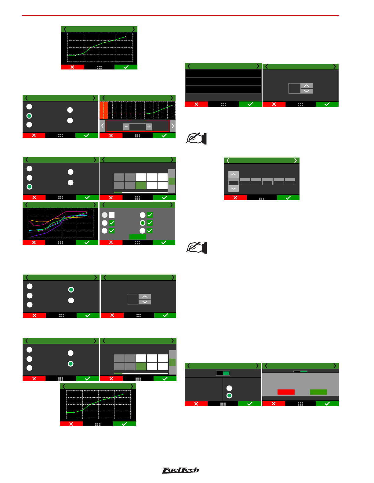
FT600
()
()
Others functions
2.50
2.00
1.50
1.00
0.50
0
0.00
Main targets 3/8
5.00
2.50
7.50
10.00
By gear and engine RPM: set up a stage for each gear, with up to 8
points per engine RPM. It is necessary that the gear change detection
function is enabled. It does not depend on 2-step.
Main targets 1/8
Time based
after 2-step
Gear and
Engine RPM
Gear elapsed
time
Single target
valve
Engine RPM
based
Wastegate pressure for gear 1 - 2/8
2400 RPM
psi
1.05
By gear elapsed time: Set up a stage for each gear, with up to 8
time points after the shift.
Main targets 2/8
Wastegate pressure table for gear 1
Time
[s]
Boost
[bar]
Main targets 8/8
Gear 1
Gear 3
Gear 5
2,50
1
0.00
50
Chart curves
OK
5,00
50
2
7,50
Gear 2
Gear 4
Gear 6
3
+
1.200.50
[bar]
70
-
10,00
2.50
2.00
1.50
1.00
0,50
0
0,00
Main targets 1/8
Time based
after 2-step
Gear and
Engine RPM
Gear elapsed
time
2,50
Main targets 8/8
5,00
Single target
valve
Engine RPM
based
7,50
10,00
250
200
150
100
50
0
0,00
Single target value: Sets a fixed pressure for BoostController. The
wastegate valve will always work this pressure.
This mode is recommended for dynamometer tests.
Main targets 1/8
Time based
after 2-step
Gear and
Engine RPM
Gear elapsed
time
Single target
valve
Engine RPM
based
Main targets 2/8
Wastegate pressure fixed target
0.0
psi
By engine RPM: Adjust the wastegate pressure according to the
engine RPM only.
[RPM]
[bar]
Revs
7500
Main targets 2/8
RPM based wategate pressure
1
1000
0.50
10000
0.50
3
2
0.70
+
30002000
[bar]
-
Main targets 1/8
Time based
after 2-step
Gear and
Engine RPM
Gear elapsed
time
Single target
valve
Engine RPM
based
2.50
2.00
1.50
1.00
0,50
0
0
Main targets 8/8
2500
Pressure
5000
Overall Trim:
It is possible to do a target pressure overall trim.
Target pressure overall trim is available to any kind of boost control
type.
Wastegate boost pressure control
General config
Launch targets
Main targets
Overrall trim
Overall trim
Wastegate target pressure overall trim
+1,00
bar
When boost control type is selected by gear, the overall trim can be
individually applied.
NOTE:
Is mandatory to have gear change detection habilitated
to use any kind of gear control.)
Overall trim
Wastegate target pressure overall trim
0,30
0,2030,15
4
2
1
0,25
0,1050,10
6
19.18 Power shift (GearController)
This feature allows gear shifting in manual transmission gearboxes
(sequential or not) without the use of the clutch (flat shifts).
NOTE:
This feature can only be used on dog engagement
equipped gearboxes. Synchronized gearboxes may be
severely damaged when trying to shift gears without
using the clutch, even if used with the power shift
feature.
When this function is activated, the white inputs number 19 and 20
will be automatically setup as gear shifter force sensor.
It is possible to setup the ignition timing during the cut in two different
ways: using the main timing table or using a fixed timing.
Main table: timing on gear shifts will use the values set in the main
timing table.
Fixed timing: adjust the ignition timing according to the selected gear.
Power shift
Power shift
Disable Enable
This feature allows flashifts
(gear shifts without using the clutch
or lifting the trottle) on dog
engagement equipped gearboxes
(Liberty Pro-Shift, Liberty Face Plate,
etc). Shifter sensor uses
white wires #19 and #20.
GearController 1/8
Ignition timing
for gear shift
Main table
Fixed timing
Ajuste rápido do mapa principal
White wires #19 or #20 are currently in use for another
Mapa de Compensação por rotação
feature. By activating the GearController these
Esta função corta a ignição durante um
inputs will be redefined. Do you want to proceed ?
Mapa de lambda para malha fechada
GearController 1/8
Desativado Ativado
Attention!
tempo configurado assim que
Assistente de mapeamento
a troca de marcha é detectada.
No
Yes
80
Page 81
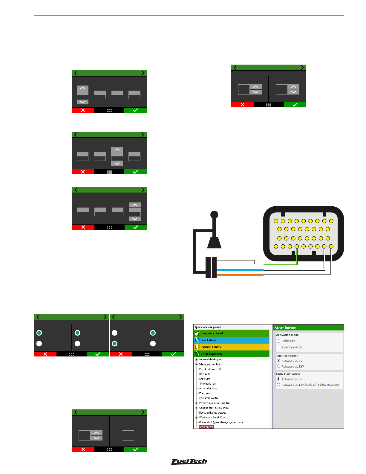
Others functions
()
()
()
()
()
()
White input#20
White
White
Blue
Orange
FT600
Cut duration: the cut duration configuration is adjusted in ms and
the values are configurable by gear.
The cut duration is used to disengage the current gear, therefore,
the next gear engagement is done by the mechanical system of the
gearbox.
Power shift
GearController 2/8
Cut duration (in miliseconds)
for gear shift:
1 - 2
170
2 - 3
160
3 - 4
200
5 - 6
230
Fixed timing: this setting fixes the ignition timing during the gear
shifts. It is configurable by gear.
Power shift () 3/8GearController
Fixed timing (BTDC)
for gear shift
1 - 2
-2,00
2 - 3
-2,00
3 - 4
-2,50
5 - 6
-4,50
Set the % of the ignition cut for each gear.
Power Shift
GearController 4/8
Cut percentual level
for gear shift
1 - 2
90
2 - 3703 - 4
80
5 - 6
60
Shifter type: select the shifter type - H/Inline pattern or sequential
shifter. Also select if your shifter is normal or inverted.
The shifter voltage cut level is used to disengage the current gear,
therefore, the force to the back means the voltage to disengage
odd gears (1st, 3rd, 5th) and force to the front refers to the cut to
disengage even gears (2nd, 4th).
Power Shift
Force to the back:
1.00
V
GearController 8/8
Shifter voltage levelfor cut
Force to the front:
4.00
V
Power shift lever connection diagram
1- connect the blue wire from the shifter to the input #19 - white wire
(pin 33 - FT600’s B connector);
2- connect the orange wire from the shifter to the input #20 - white
wire (pin 34 - FT600’s B connector);
3- connect the two white wires from the shifter to the green/black wire
from the ECU - sensors ground (pin29 FT600’s B connector);
Connector B
5
Strain Gage Sensor
3
12
10
11 121314
18 19 20
2627282930 31 32 33 34
4
21 22
6789
15 16
17
23 24 25
When forcing the shifter, check the voltage reading in the FT600
diagnostic panel or in the log, while shifting gears.
- If the voltage goes from 2.5V towards 5V, select the Normal
shifter type.
- If the voltage goes from 2.5V towards 0V, select Inverted as
shifter type.
Power Shift
H pattern
Sequential
GearController 6/8
Transmission type
Normal
(5V to the front)
Inverted
(0V to the front)
Power Shift
H pattern
Sequential
GearController 6/8
Transmission type
Normal
(5V to the front)
Inverted
(0V to the front)
With the car stopped, push the shifter to the front and check the
voltage read in the FT600 diagnostic panel. The recommended value
is between 4 and 4.5V (or 0.5 and 1V - inverted transmission).
If the lever signal reaches 0V or 5V easily, lower the sensitivity gain
in order to keep it below 5V and above 0V, the shifter voltages must
never hit these limits.
Power Shift
GearController 7/8
Sensitivity gain for
shifter sensor
7 2.55
Read
V
Green/Black Ground for sensor s-
White input#19
19.19 Start Button
This function allows the control of the vehicle’s starter motor through
an output (blue, gray or yellow wires) and an input (white wire) or
through the FT screen.
81
Page 82
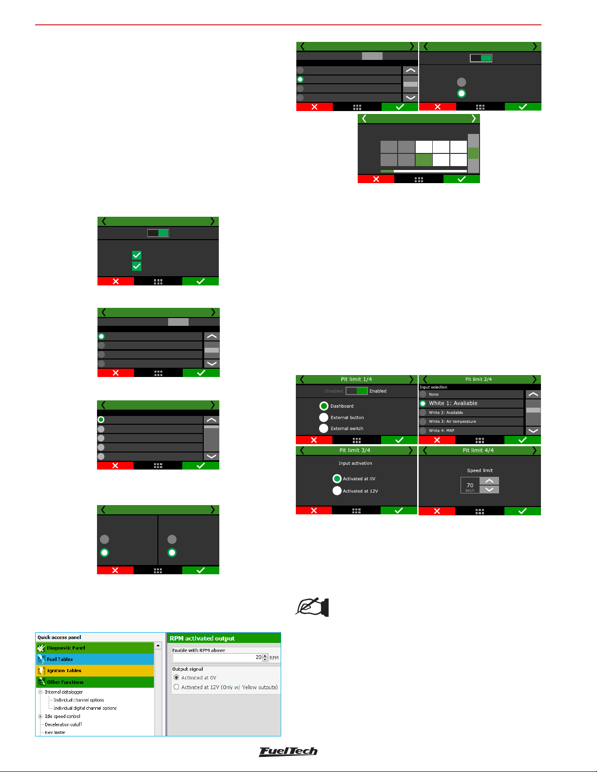
FT600
Others functions
Select whether you want to start the engine through the FT LCD screen
(must setup the "Start Button" item on the FT dashboard" or through
an external switch
If Dashboard is chosen the starter motor remains engaged while the
button is being pressed and until the engine RPM goes above the "RPM
for engine start" (set in the Engine Setup menu". As soon as the engine
is running, the function of the button on the dashboard is now changed
to turn the engine off when pressed (by cutting fuel and spark).
When external switch is selected.
Select whether the input is activated when it receives 0V (ground)
12V. The output that actives the starter relay can be programmed
whether to send 0V or 12V when activated.
Start button 1/4
Disabled Enabled
DashBoard
External button
Select an output to activate the engine starter relay.
Start button 2/4
Test
Grey Avaliable7:
Grey Tachometer output8:
Yellow Avaliable1:
Yellow Avaliable2:
Test output:
Output selection
Cold start auxiliary 1/3
None
Blue 5 Cold start auxiliary:
Blue 6Avaliable:
Blue 7Avaliable:
Test :output
Output selection
Test
Temp Motor
Time
Cold start auxiliary 3/3
Time table by temperature
[]°C
[S]
1
-20,0
3,5
Cold start auxiliary 2/3
Disabled
Output signal
3
2
20,00,0
3,5
3,5
Enabled
Activated at 0V
Activated at 12V
+
[S]
-
19.21 Internal MAP sensor signal output
On this menu it’s possible to set up an output to send the singal of
the internal MAP sensor to another equipment like a Datalogger for
example.
19.22 Pit limit
This feature limits the speed to a set value, it can be activated through
a dashboard button, an external button or an external switch.
External button: will keep the function activated for as long as it’s
pressed, deactivating when the button is released.
External switch: When pressed, it’ll keep the function activated until
it’s pressed again, the same applies for the dashboard button.
Both can be set up using a white wire or via CAN 2.0.
Select the input to the start button.
Input selection
Start button 3/4
None
White O2 General1:
White 2: 2-step
WhiteiConditioning3: Ar
WhiteOil pressure4:
Define which is the activation signal to the input button and to the
output if 12V or 0V.
Start button 4/4
Output activation
Activated at 0V
Activated at 12V
Input activation
Activated at 0V
Activated at 12V
19.20 RPM activated output
This function allows enable output when the RPM is above a determined
value.
19.23 Active traction control
This function actively controls the vehicle traction by changing ignition
timing and the electronic throttle to try to obtain the best possible
traction on various track conditions.
NOTE:
To use this feature, the vehicle must have at least 2
wheel speed sensors with speed differences between
them.
82
Page 83
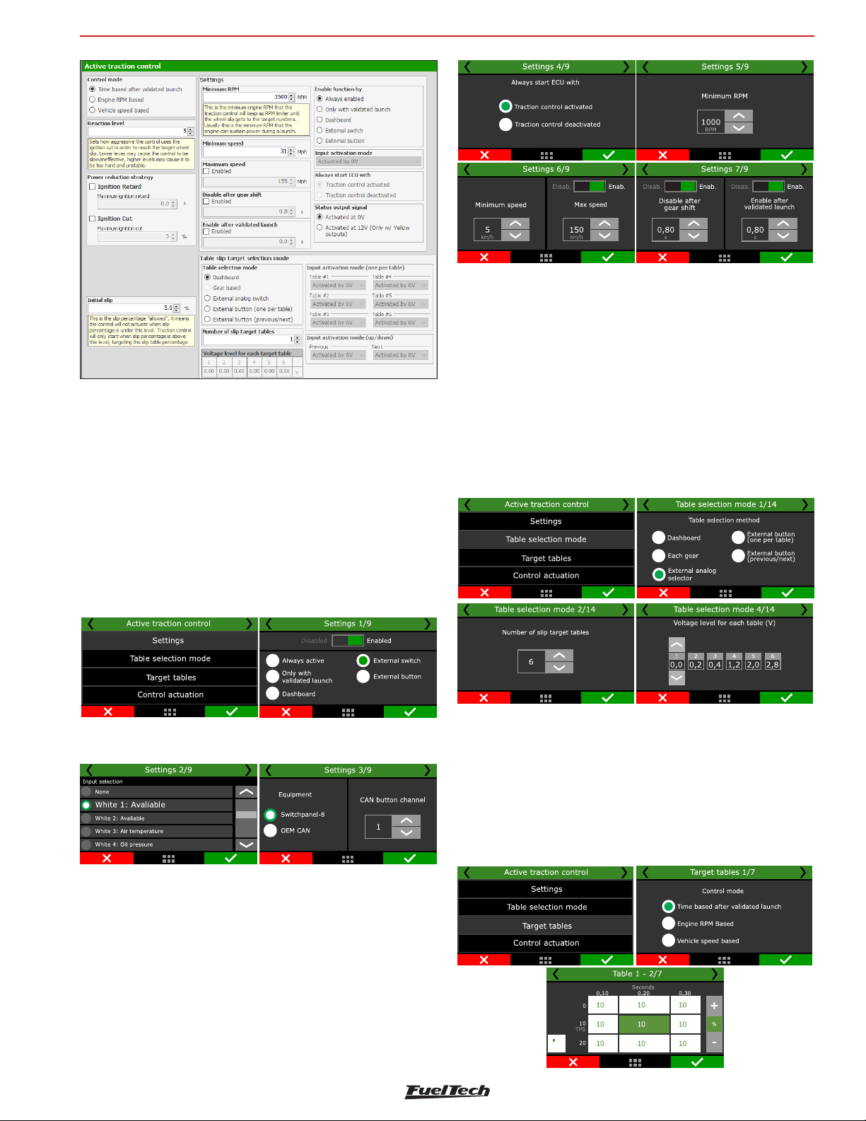
Others functions
Settings
On this menu it’s possible to set up all the options regarding the
traction control.
Always active: The control is always active and will function whenever
the parameters defined in the settings are met.
Only with validated launch: the control will only function after a
valid launch (when the settings for 2step are reached before launch)
Dashboard: Activates the control through a button on the dashboard.
External switch: Activates the control though an external on/off
switch.
External button: Activates the control while the button is pressed,
deactivates when released.
FT600
Table selection mode
Here it’s possible to set the quantity of tables and how to select them.
Dashboard: When selected, a button must be set up at “dashboard
setup” menu, this button will switch between tables.
By gear: When selected, the tables will be assigned according to the
current gear. That being: first gear > table-1, second gear> table-2,
and so on.
External analog selector: When selected, it’s possible to use an
external multi-position selector by setting the voltage level for each
table.
If External button or External switch is selected, a white wire or CAN
(Switchpanel-8 or OEM) must be set up.
After one of the activation options are selected, it’s possible to choose
whether the control will be enabled or disabled when the ECU starts.
Next the minimum RPM must be set, this is the lowest RPM the control
will allow the engine to drop to, and below this RPM the control will
not actuate.
The same principle is applied to the settings of minimum and maximum
speed (of the reference wheel), the control will not actuate below the
minimum speed or above the maximum speed.
There’s also the possibility to deactivate the control right after a gear
change is detected, allowing for some wheel slip during this set
amount of time.
Target tables
The tables can be set up three different ways.
Time based after validated launch: creates a 6x16 TPS% by Time
after validated launch, target slip table.
Engine RPM based: creates a 4x8 TPS% by engine RPM target slip
table.
Vehicle speed based: creates a 6x16 TPS% by wheel speed target
slip table.
83
Page 84
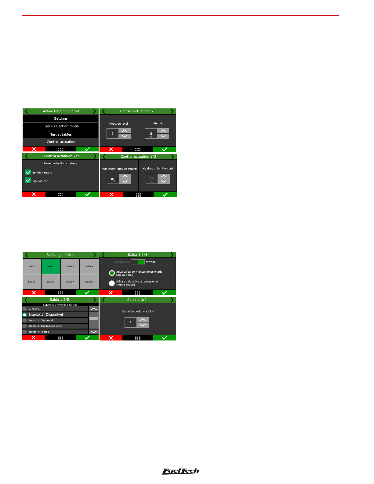
FT600
Control actuation
In this menu it’s possible to set up how the traction control will actuate
on the vehicle.
The reaction level can be set between 1(less agressive) and 10(very
agressive), and it dictates how the traction control will actuate.
Initial slip is the minimum wheel slip allowed, this is needed when the
vehicle launches to get the car moving easily.
The strategy of the traction control to maintain the slip target is to
retard the timing first, and if the slip is still increasing it will start to
cut the ignition too.
Others functions
19.24 Generic Outputs
In this menu it’s possible to set up to 8 different outputs for various
uses like activating exhaust diverts, turn off alternators during drag
races, and many others that require datalogging. These outputs must
be activated by either an white input or via CAN with the SwitchPanel-8.
84
Page 85
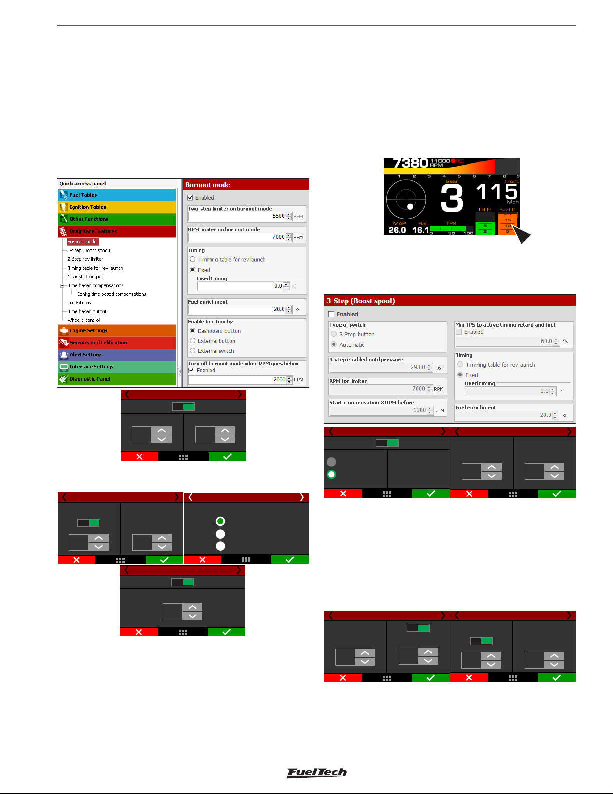
Drag race features
FT600
20. Drag race features
This menu gathers all options normally used in drag race applications.
All the time based features start after releasing the 2-step button which
indicates the moment when the vehicle launched.
20.1 Burnout mode
The Burnout Mode is a function used to facilitate the processes of
warming up the tires and using the two-step.
When pressing the two-step button, the two-step function is activated.
• by an external button* - a white input is required. One click to
enable and another to disable the burnout mode.
• by an external switch* - similar to the button, but in this case the
function is enabled while the input is grounded.
* In the FTManager, this setup is at “Sensors and calibration” - “Inputs”
The burnout mode can be automatically disabled by RPM. When the
engine RPM is below an editable value. This option is not available
for “external switch” option.
20.2 3-step (boost spool)
The 3-step is quite similar to the 2-step function, however, with more
aggressive strategies to assist in the boost spool.
Burnout 1/3
4000
RPM
Disabled
Enabled
Burnout rev limiterRev limiter
7500
RPM
When Burnout mode is activated, it disables the standard RPM Limiter,
instead the ECU uses this RPM limiter as the engine’s RPM limit.
Lock 2-step
ignition timing at:
Map
-16,0
°
Burnout 2/3
Fixed
Burnout 2-step
fuel enrichment
45
%
Disabled
mode when goes down of:RPM
Burnout 3/3
Turn off burnout
2000
RPM
Enabled
Burnout 3/5
Burnout activation mode
DashBoard
Burnout external button
Burnout external switch
But when the two-step button is being pressed, the value considered
is the one set for the two-step parameter. The values adopted for
ignition timing retard and enrichment are the ones configured on the
two-step function.
There are 3 different ways to enable the burnout mode:
• by dashboard button: a touchscreen button in the FT600
dashboard enables the function.
3-Step (Boost spool/footbrake) 1/5
Disabled
3-step button
Automatic by boost
Enabled
Automatic activation uses the
same trigger as 2-step (button
or speed) and automaticaly
switch to 2-step parameters
when boost rises to what
was set up.
3-Step (Boost spool/footbrake) 3/5
3-step enabled
until boost reaches:
2,50
bar
7000
RPM
Cut on:
There are two ways to activate this function, one uses an external
button (must use a white wire attached to a button, usually on the
foot brake) and the other is through 2-step button.
In this case, you must press the 2-step button and the 3-step will be
activated until the engine reaches a predefined boost pressure, at this
point the 3-step will be deactivated and the 2-step will be activated.
If using an external button to trigger the 3-step, when it is triggered
simultaneously with 2-step button, the 2-step will prevail.
3-Step (Boost spool/footbrake) 4/5
Disab.
Start correction
before:
200
RPM
Minimum toTPS
activate timing retard
and enrichment
Enab.
45
%
3-Step (Boost spool/footbrake) 5/5
Ignition timing
Map
-16,0
Fixed
°
Fuel
enrichment
45
%
It is possible to start the 3-step mode before the RPM rev limiter and
to set a minimum TPS value to activate it.
85
Page 86
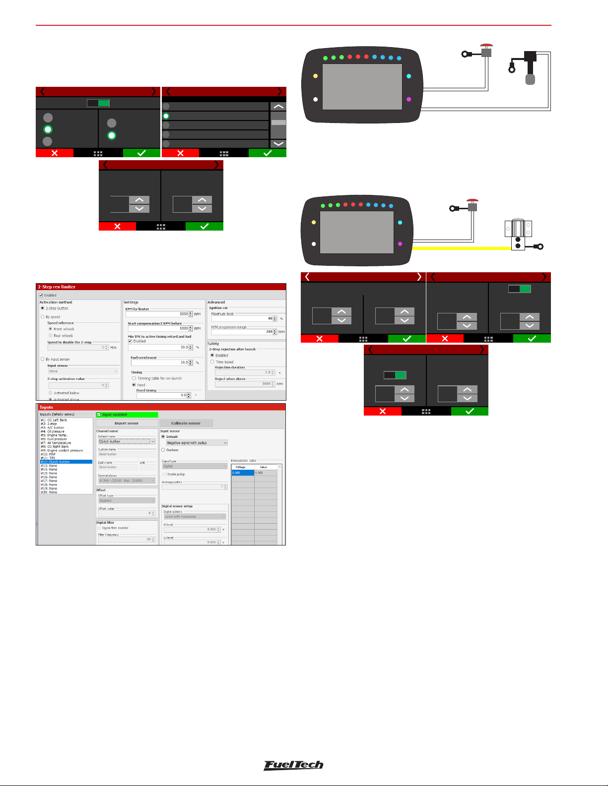
FT600
Clutch
Line Lock
Drag race features
20.3 2-step rev limiter
The two-step active with a retarded ignition timing, and a mixture
enrichment given in percentage (also programmable).
2-step rev. limiter 1/6
Disabled
2-step button
By speed
Input sensor
Enabled
Front wheels
Rear wheels
Speed for 2-step
deactivation
4
mph
Input selection
2-step rev. limiter 3/6
When pressing the two-step button, usually installed on the steering
wheel or driven by a launch control / transbrake switch, the system
activates an ignition cut in a programmable RPM.
In the FTManager, this setup is at “Sensors and calibration” - “Inputs”
2-step rev. limiter 2/6
Nenhuma
None
Branco 1: Disponível
White 1: 2-step
Branco 2: Disponível
White 2: Oilpressure
Branco 3: Temperatura do ar
White 3: Air temperature
Branco 4: Pedal 1
White 4: TPS
Cut on:
7000
RPM
Ground
Button
Clutch
Pedal
White input#2
White wire
Ground
2-Step
Button
Line lock
Use a yellow output to control the line lock solenoid and setup this
output as Line Lock through the FTManager or the screen. The other
side of the solenoid must be connected to the battery negative or
chassis.
2-step rev. limiter 4/8
Maximum level
90
%
Ignition cut
RPM progression range
200
RPM
Ground
White input#2
Line Lock Yellow wire output
Start correction
1000
RPM
2-step rev. limiter 5/8
before:
2-Step
Button
Dislab.
Minimum toTPS
activate timing retard
and enrichment
45
%
Solenoid
Ground
Enab.
Clutch switch: for drag racing vehicles with manual transmission
and clutch, this switch tells the ECU whenever the pedal is pressed.
Connected to a white input.
This is an auxiliary feature to the 2-step and it helps releasing the
2-step at the same moment the clutch is being released.
If the clutch switch is pressed when the 2-step is deactivated, nothing
happens, but, if the 2-step is active, then the clutch switch will hold
the 2-step enabled until the clutch is released. The 2-step button can
be released after this that the 2-step feature will still be active.
The 2-step button still works as usual. The clutch switch is fully optional.
Clutch switch electrical diagram
Connect the clutch switch to any white input and setup this input
through the FTManager or through the screen. The other side of the
clutch switch must be connected to the battery negative or chassis.
86
2-step rev. limiter 6/8
Ignition timing
Map
-16,0
°
Fixed
Fuel
enrichment
45
%
It is possible to set the ignition cut maximum level, that is the percentage
of ignition events cut to keep the engine under the rev limiter.
The RPM progression range acts as a smoothing for ignition cut.
Example: rev limiter at 8000rpm, RPM progression range at 200rpm.
From 8000rpm the ignition cut level will gradually increase until it
reaches 90% cut at 8200rpm.
Percentages less than 90% may not keep the engine under the rev
limiter. Bigger RPM progression range tend to stabilize more smoothly
the rev limiter, but allows the RPM to pass the RPM set as rev limiter.
These numbers are valid to all kinds of ignition cut, with the exception
of time based compensations (time based RPM and driveshaft RPM/
wheel speed) and 2-step. These features have their own parameters.
For inductive ignition systems it is recommended to use 90% maximum
level and 200 RPM progression range. For capacitive system, like
MSD, it is recommended to use 100% maximum level and 1 RPM
progression range.
The “Start compensation X RPM before” helps to spool the turbo and
have a more stable rev limiter.
The minimum TPS to activate timing retard and fuel enrichment allows
the driver to hold the engine in the rev limiter without any compensation
when not needed.
The time based compensations will only work after the release of a
valid 2-step. This means hold the 2-step button with more then 50%
TPS or reach the rev limiter on time at least.
Page 87
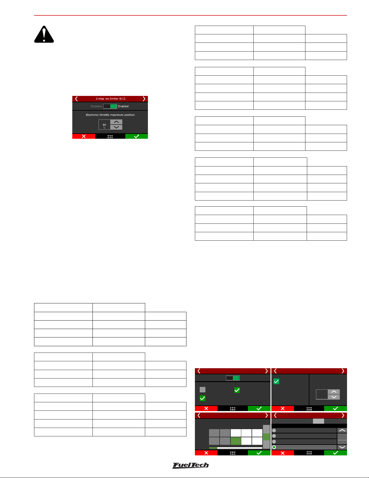
Drag race features
FT600
ATTENTION:
When the 2-step is by wheel speed, its working
can be checked through the first page of
Diagnostic Panel, since it is not being used any
2-step button input.
A maximum electronic throttle opening can be set, allowing the driver to
launch with the pedal to the floor while the ECU controls the maximum
position of the throttle to aid in getting standardized launches.
To prevent the driver to activate the 2-step on a run, there are 2
safety parameters. Block 2-step by time or by RPM. This way, even if
th driver press the 2-step button, it will not activate before the time
slip or above the RPM.
When using the 2-step by an input sensor, you must indicate an above
or below value which the 2-step must be considered active.
2-Step: Speed 3-Step: Auto
Speed MAP pressure Active function
Lower than target Lower than target 3-step
Lower than target Higher than target 2-step
2-Step: Sensor 3-Step: Button
Sensor Button 3-step Active function
Active condition Released 2-step
Active condition Pressed 3-step
Not Active condition Pressed 3-step
2-Step: Sensor 3-Step: Auto
Sensor Button 3-step Active function
Active condition Lower than target 3-step
Active condition Higher than target 2-step
2-Step: CAN 3-Step: Button
Button 2-step CAN Button 3-step Active function
Pressed Pressed 3-step
Pressed Released 2-step
Released Pressed 3-step
2-Step warning LEDs
2-step without valid launch condition: Yellow
2-step with valid launch condition (ign cut or TPS): Green
Invalid launch: Red blinking for 5 seconds
Valid Launch: LED is turned off (it would be green until a valid launch)
2-step + staging control: Blue
Staging control button without 2-step: Purple
Active function tables
The following tables show what will be the active function with the
2-step and 3-step combinations
2-Step: Button 3-Step: Button
Button 2-step Button 3-step Active function
Pressed Pressed 3-step
Pressed Released 2-step
Released Pressed 3-step
2-Step: Button 3-Step: Auto
Button 2-step MAP pressure Active function
Pressed Lower than target 3-step
Pressed Higher than target 2-step
2-Step: Speed 3-Step: Button
Speed Button 3-step Active function
Lower than target Released 2-step
Lower than target Pressed 3-step
Higher than target Pressed 3-step
2-Step: CAN 3-Step: Auto
Button 2-step CAN MAP pressure Active function
Pressed Lower than target 3-step
Pressed Higher than target 2-step
20.4 Linelock Brake Control
This function allows the use of a line lock solenoid to keep the brake line
of the trailing wheels pressurized and to facilitate the exit, avoiding that
the pilot has to modulate the brake with the foot at the time of the exit.
For correct use of this function press the brake pedal, operate the
2-step, release the brake pedal and the line lock will be activated. When
you release the 2-step, the Line Lock solenoid is automatically disabled.
Select whether to activate the line lock on burnout, 3-step and / or
2-step modes.
An output must be configured as “Output line lock”.
Brake pressure control: This function enables brake pressure control
through a PWM curve. This is used to lower the brake line pressure to
a desired value and standardize the launches.
It is necessary to have a white input must be setup as “Brake pressure”
connected to a 1500psi pressure sensor.
Line lock brake control 1/5
Disabled Enabled
Burnout
3-step
Line lock brake control 3/5
Pressure
[]PSI
PWM
[%]
Acionamento
2-step
PWM table by pressure
1
40
0
Line lock brake control 2/5
Brake pressure
control
Brake pressure sensor
Must be setup for
this function
Line lock brake control 4/5
Test output:
3
2
50
+
9080
100
None
Blue Avaliable5:
[%]
Blue Avaliable6:
-
Blue Avaliable7:
Select line lock output
PWM frequency
15
Hz
Test
87
Page 88
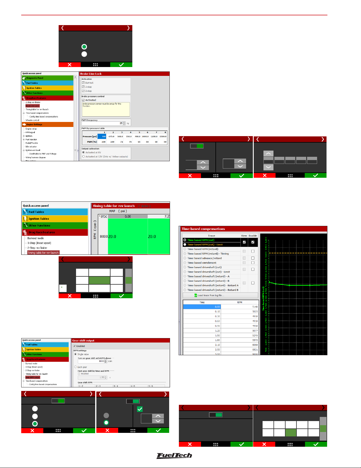
FT600
Drag race features
Line lock brake control 5/5
Output activation
Activated at 0V
Activated at 12V
20.5 Timing table for rev launch
This timing table is only used for burnout mode, 2-step and 3-step. This
is not a compensation table, but a table with absolute timing values,
which ignores any other timing table or compensation.
Select the desired output, all the outputs will be displayed, except the
ones used for injection and ignition. In the FTManager, this setup is at
“Sensors and calibration” - “Inputs”.
The gear shift by single value sends a signal every time the engine
reaches the selected RPM. When using the each gear mode, each
gear shift will be on its own RPM. To use this mode the gear detection
must be activated.
The gear shift is enabled after the 2-step is released, so, after the last
gear the 2-step must be activated again to perform the shifts again.
When selecting this mode, the “First gear shift by time and RPM” will
be available. It allows the gear shift to be performed not only by RPM,
but also by time. This means that there are 2 conditions (time and
RPM) to be met to gear shift. It is not possible to use this control with
automatic transmissions with more than one solenoid.
Disab.
Lock time between
gear shift
0,60
S
Gear shift output 3/4
Enab.
Pulse trigger
time:
0,25
S
Gear change output 3/3
Gear change RPM
2-3
1-2
7500
7500
3-4
7000
4-5
7000
5-6
6500
20.7 Time based fuel enrichment
Enables a time based fuel compensation that starts after the
2-step deactivation. This compensation is a time (seconds) versus
compensation (%) feature. After you enter the table, a graph will be
displayed.
Spool assist table
MAP
2,00
1,00
0,00
2000
20,0
4000
6000
RPM
19,7
20,0
20,0 20,5
19,7
20,0
19,5
21,0
+
[°]
-
20.6 Gear shift output
This feature allows switching on an external solenoid to shift the gears.
The activation strategy can be either by a fixed RPM value for all the
gears or different RPM for each gear just like the shift light feature.
Gear shift output 1/16
Disabled Enabled
Automatic shift by RPM
Manual upshift input button
Automatic and Manual shift allowed
Gear change output 2/3
Disabled Enabled
RPM setup
Single value
Each gear
First gear
change by time
1,50
s
Time based advanced/retard timing
Enables a time based timing compensation that starts after the 2-step
deactivation. This compensation is a time (seconds) versus degrees
BTDC (º BTDC) feature. After you enter the table, a graph will be
displayed.
Time based enrichment 1/3
Disabled Enabled
Activates a fuel compensation
by time after the lauch.
Alloes the use of richer or poorer
mixtures according to the
time after the lauch.
Time based enrichment 2/3
Time based fuel enrichment curve
1
0,00
+50
2
0,55
+35
Time
Percent
[s]
[%]
1,25 3,002,50
+15
+30
53
4
+
[%]
0
-
88
Page 89
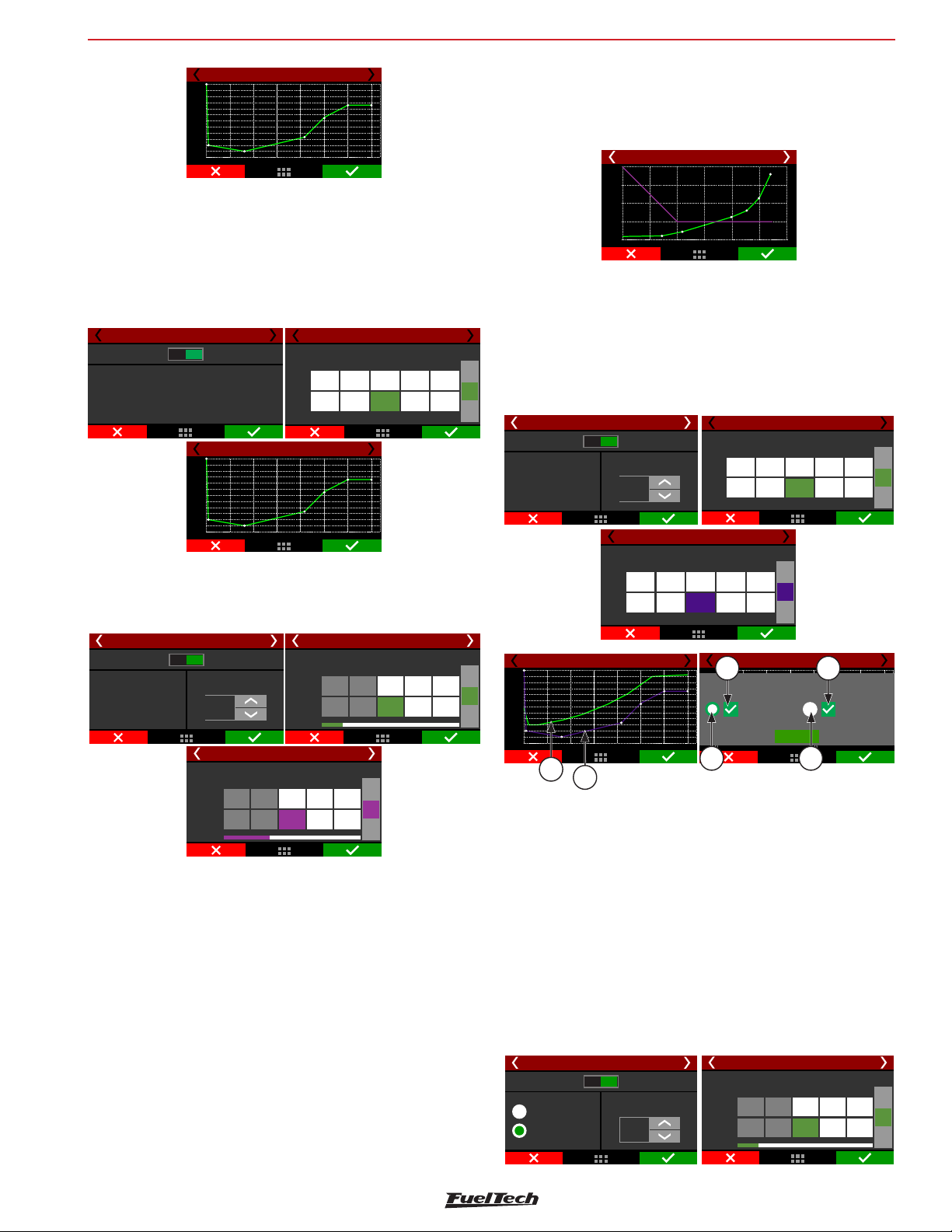
Drag race features
07
[]
03
[]
FT600
Time based enrichment 3/3
+100
+80
+60
+40
+20
0
-20
0,00
2,00 3,00 4,005,006,00 7,00
1,00
Time based revolution limiter
The RPM control is based on seven RPM and time points that can be
determined as shown in the image above.
This function is frequently used in drag racing cars, because it makes it
easier to control the vehicle, once it allows the traction to be recovered
through an ignition cut ramp.
Time based advance/retard 1/3
Disabled Enabled
Activates a time based timing
map, starting at the lauch point.
Allows the power control
on specific moments.
Time based advance/retard 3/3
0,00
-2,00
-4,00
-6,00
-8,00
-10,0
-12,0
0,00
1,00
2,00 3,00 4,005,006,0
Time based advance/retard 2/3
Time based advance/retard curve
1
0,00
-10,0
2
0,55
-8,50
Time
Degrees
[s]
[º]
,00
1,25
-5,00
-2,00
53
4
3,002,50
+2,00
+
[°]
-
Time based speed (cut)
This feature is the same as the time based RPM (cut) but instead of
using the engine RPM, it uses the wheel speed or the driveshaft RPM.
[]RPM
Time
Revs
[s]
2
60
Time based RPM (cut)
RPM based ignition map
1
0,00
4500
3
+
2,701,00
[%]
70
-
2
4500
1,250,80
4700
3
+
RPM
-
Time based RPM (cut) 1/4
Disabled Enabled
Time based RPM (cut)
performs ognition cuts to
keep engine RPM under
a predefined curve.
RPM progressive range
200
RPM
Time based RPM (cut)
Time
[s]
Cut
[%]
Ignition cut curve
1
0,00
50
It will perform ignition cut to keep the wheel speed/driveshaft RPM
under a predefined curve.
The “Time based RPM (cut) - Limit” is the maximum level, which
means the percentage of ignition events that will be cut to keep the
engine under the rev limiter.
The RPM progression range acts as a smoothing for ignition cut.
Example: rev limiter at 8000rpm, RPM progression range at 200rpm.
From 8000rpm the ignition cut level will gradually increase until it
reaches 90% cut at 8200rpm.
Values less than 90% may not keep the engine under the rev limiter.
Bigger RPM progression ranges tend to stabilize more smoothly the
rev limiter, but allows the RPM to pass the RPM set as your rev limit.
For inductive ignition systems it is recommended to use 90% maximum
level and 200 RPM progression range. For capacitive system, like
MSD, it is recommended to use 100% maximum level and 1 RPM
progression range.
The last screen will show the graph.
10000
9000
8000
7000
6000
5000
4000
0,00
Time based RPM (cut)
1,001,502,0
0,50
,00
2,50
Time based RPM (retard)
This feature is very similar to the time base RPM (cut), instead of
cutting the ignition, it will retard the timing, to have a smoother way to
control power and torque to the wheels. The function starts after 2-step.
It is recommended to use this function together with the Time based
RPM (cut) to have a better control of the engine, this way the control
itself will be smoother.
Time based RPM (retard) 1/4
Disabled Enabled
Time based RPM (retard)
enables a timing retard
table to keep engine
RPM under a
predefined curve.
Time based (retard) 4/4RPM
0,0
-2,0
-4,0
-6,0
-8,0
-10,0
-12,0
0,00
2,00 3,00 4,00 5,00 6,00 7,00
1,00
1
RPM progression range
Time
Degress
[º]
2
200
RPM
0,00
[s]
-10,0
Time based (retard) 3/4RPM
Ignition retard curve
1
2
0,55
-8,5
1,25
-5,0
Time based (retard) 2/4RPM
RPM based ignition retard curve
1
2
0,55
0,00
3500
3800
53
4
3,002,50
+2,0
-2,0
Time based (retard) 4/4RPM
4
Revs
2,00 3,00 4,005,00 6,00 7,00
1,00
-2,00
-4,00
-6,00
-8,00
-10,0
-12,0
Time
Revs
[]RPM
0,00
[s]
0,00
3
1,25
3700
+
[°]
-
Chart curves
OK
3
4500
4
4
3,002,50
5500
Degrees
53
+
RPM
-
1 - Green Speed curve;
2 - Purple speed curve;
3 - Buttons for chart selection that will be in the upper layer;
4 - Check boxes to enable or disable graphic display.;
Time based speed (cut)
This feature is the same as the time based RPM (cut) but instead of
using the engine RPM, it uses the wheel speed (with a wheel speed
sensor or by calculating speed) or the driveshaft RPM. It will perform
ignition cut to keep the wheel speed/driveshaft RPM under a predefined
curve. Generally speaking, this speed/RPM control seeks to limit the
wheel speed during the run.
Time based driveshaft (cut) 1/4
Disabled Enabled
Driveshaft RPM
Speed (traction)
Speed progression range
20
Kmh
Time based driveshaft (cut) 2/4
Speed based ignition cut
Time
[s]
Speed
[kmh]
0,00
1
57
55
+
1,100,50
[kmh]
75
-
3
2
89
Page 90
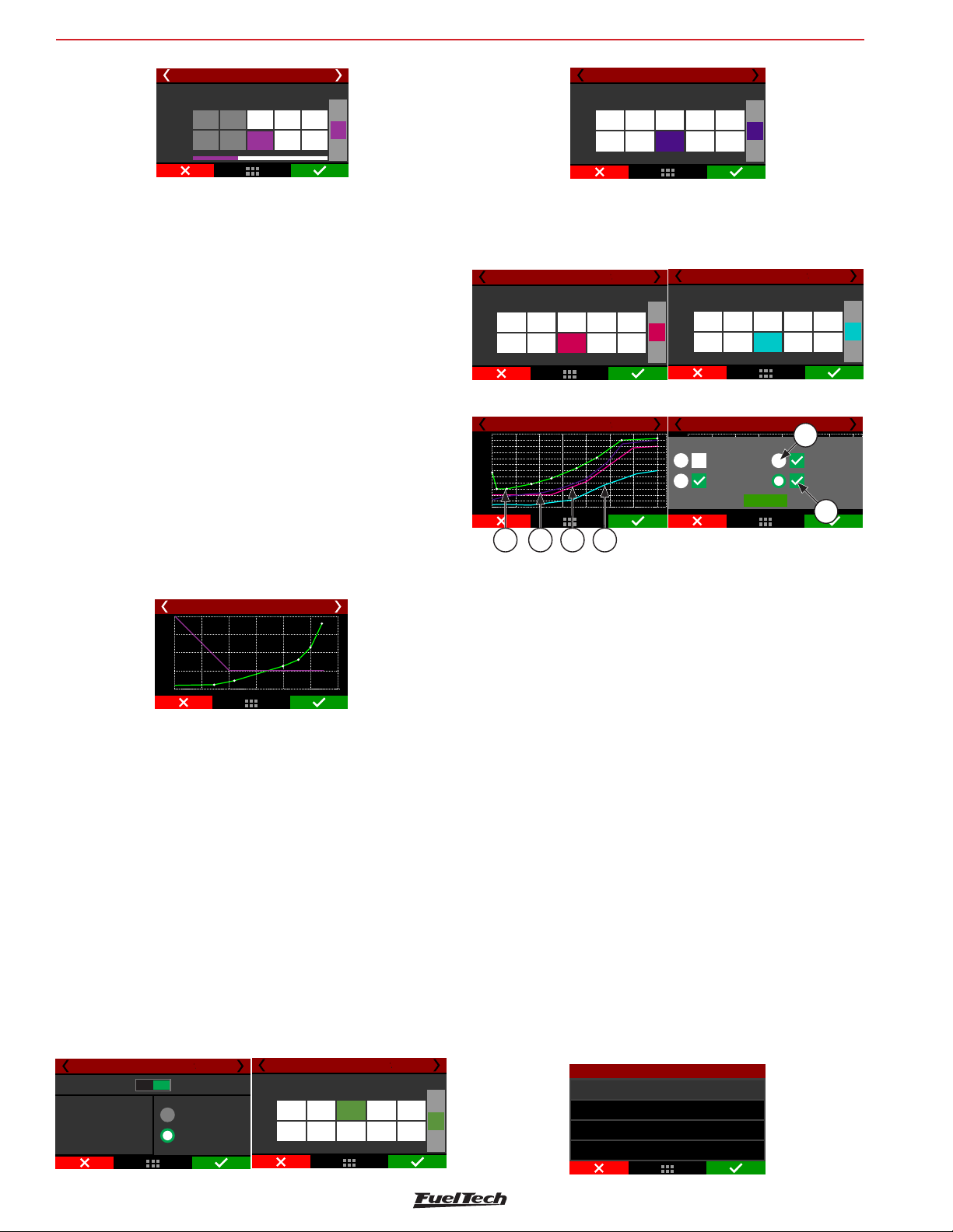
FT600
Degrees
07
Drag race features
Time based driveshaft (cut) 3/4
Ignition cut curve
Time
[s]
Cut
[%]
1
0,00
50
3
2
60
+
2,701,00
[%]
70
-
The first screen will briefly explain how the feature works and it will
ask what the speed reference is, if it is a wheel speed or drive shaft
RPM. You must have a wheel speed sensor or a driveshaft RPM sensor
enabled to use this feature.
The first parameter to be set is the speed/RPM progression range,
which is the Speed/RPM range from start the ignition cut to its
maximum level.
A 10 Mph speed progression range means that if your control starts
at 80 Mph, the ignition cut maximum level will be at 90 Mph.
The next screen is the wheel speed/driveshaft RPM versus time table.
After the 2-step, every time the speed/RPM goes above the curve, the
ECU will perform ignition cuts.
Percentages less than 90% may not keep the engine under the rev
limiter. Bigger RPM progression range tend to stabilize more smoothly
the rev limiter, but allows the RPM to pass the RPM set as rev limiter.
For inductive ignition systems it is recommended to use 90% maximum
level and 200 RPM progression range. For capacitive system, like
MSD, it is recommended to use 100% maximum level and 1 RPM
progression range.
Time based driveshaft (cut) 4/4
10000
9000
8000
7000
6000
5000
4000
0,00
1,00 1,50 2,00 3,00
0,50
2,50
Time based speed (retard)
This feature reads the wheel speed (or the driveshaft RPM) and applies
ignition compensation, according to the two RPM curves (A and B)
to control launch.
The basic idea is to retard the ignition timing, reducing power to
the wheels. When the wheel speed reaches the programmed in the
“speed curve A”, the ECU starts the programmed retard in the “delay
curve A point”.
As the speed increases, and goes toward the curve “B” speed, the
retard applied to the timing (that is interpolated between the two retard
curves) is incremented. Thus, if the initial retard made by curve A is
not sufficient to hold the speed of the vehicle, the retard will increase
as much as the RPM increase.
In cases where the speed/RPM exceeds the limits of the curve “B”,
the maximum retard (entered in curve B) will be applied.
Time based speed (retard) 1/6
Disabled Enabled
Time based speed control allows
the car to regain traction
through a timing retard ramp.
Driveshaft RPM
Speed (traction)
Time based speed (retard) 2/6
1
Time
Speed
[mph]
0,55
0,00
[S]
3800
3500
Speed curve A
2
1,25 3,002,50
3700
5000
53
4
5500
+
[s]
-
Time based speed (retard) 3/6
Time
Speed
[mph]
Speed curve B
1
2
0,25
0,00
[s]
5
15
0,45 1,500,95
15
53
4
55
120
+
mph
-
The first screen allows to select the speed/RPM reference (wheel
speed or driveshaft RPM). You must have a wheel speed sensor or a
driveshaft RPM sensor enabled.
The next screens will show the speed/RPM curves A and B.
Time based speed (retard) 4/6
1
Time
0,00
[s]
Degrees
-10,0
[°]
Retard curve A
2
0,55
1,25
-8,5
-5,0
-2,0
53
4
3,002,50
+2,0
+
[°]
-
Time based speed (retard) 5/6
Retard curve B
1
0,00
-10,0
2
0,55
-8,5
Time
[s]
[°]
1,25
-5,0
-2,0
53
4
3,002,50
+2,0
+
[°]
-
After this, the ignition retard curves A and B
Time based speed (retard) 6/6
10000
8500
7000
5500
4000
2500
1000
0,00
1,00
2,00 3,00 4,00 5,00 6,00 7,00
Time based speed (retard) 6/6
10000
8500
7000
5500
4000
2500
1000
0,00
Chart curves
Speed A Speed B
Retard A Retard B
2,00 3,004,00 5,00 6,0
1,00
OK
5
,00
6
1 2 3 4
1 - Green speed curve A;
2 - Purple speed curve B;
3 - Pink timing retard curve A;
4 - Blue timing retard curve B;
5 - Buttons for chart selection that will be in the upper layer;
6 - Check boxes to enable or disable graphic display;
In the end, a graph will be displayed with all the curves (speed/RPM
A and B, retard A and B)
Note that the speed and retard curves shown on the graph form speed
and retard zones. They have the following characteristics:
• When below the curve A, there is no retard applied to the engine;;
• When the speed/RPM is equal to the programmed curve A, the
ignition retard is equal to the programmed in curve A;
• For speed/RPM between the two curves, the retard is interpolated,
in other words, the more the speed/RPM exceeds the curve A
towards to curve B, the more retarded the timing will be;
• If the speed/RPM programmed is overcoming the curve B, the
ignition retard is equal to the value programmed in curve B.
20.8 Pro-Nitrous
This feature controls up to 6 time based nitrous stages, with individual
settings for each stage.
Pro-Nitrous
Pro-Nitrous settings
Pro-Nitrous fuel table
Pro-Nitrous fuel compensation
Pro-Nitrous timing table
90
Page 91
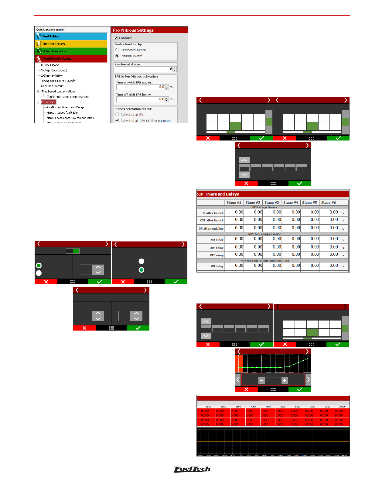
Drag race features
Pro-Nitrous settings
To active the Pro-Nitrous it is mandatory fulfill 3 requirements:
1. Active the Pro-Nitrous button (external switch in one of the white
inputs or a dashboard button in FT600 display).
2. The elapsed time after 2-step cannot be more than 15s, otherwise
Pro-Nitrous will not be turned on. In other words, the vehicle must
launch in less than 15s after 2-step deactivation.
3. TPS must be above minimum percentage configured.
FT600
Also, you will be able to pedal the throttle to get back traction.
The RPM activation window is necessary to protect the engine, not
allowing having a nitrous shot in a low RPM or by deactivating nitrous
before the rev limiter
The Pro-Nitrous timers and delays table gathers the on and off settings
for stages and compensations. A pedaling delay can also be set,
so, if the driver pedals in a run, the Pro-Nitrous can be reactivated
progressively.
In the FTManager, this table is as shown below.
Pro-Nitrous settings 12/13
Pro-Nitrous activation window
1
Upper
Lowe
2000
8000
4000
8000
53
2
4
5000
8500
60006000
8500
8500
Pro Nitrous fuel table 1/7
Delay to start fuel compensation
2
1
0,30
0,25
+
Turn on
RPM
Turn off
-
(in seconds)
0,2030,15
Pro-Nitrous settings 13/13
1
0,00
10,00
4
0,1050,10
Pro-Nitrous Stages
2
1,00
2,00
10,00
4,00
6
6,00
53
4
5,953,95
10,00
+
[s]
-
With these 3 requirements fulfilled, the Pro-Nitrous stages will start and
follow the configured time. The fuel and timing compensations will also
start at this point. If any condition fails, the Pro-Nitrous is deactivated
and FT600 will use fuel, timing and O2 closed loop main tables.
Pro-Nitrous settings 2/13
Disabled Enabled
Enable function by
Dashboard Switch
Pro-Nitrous switch
Number of stages
6
Pro-Nitrous settings 11/13
TPS to Pro-Nitrous activation
Turn on with above:TPS
95,0
%
Turn off with below:TPS
90,0
Pro-Nitro 4/14
Stages activation outputs
Activated at 0V
Activated at 12V
%
The first parameter to be set is the enabling mode:
• Dashoboard button: a touchscreen button in the LCD screen that
can be found in the Dashboard settings menu.
• External switch: a white input must be used with an external
switch. While the input is grounded, the Pro-Nitrous will be on.
FuelTech FT600 allows firing the solenoids by switching 12V or 0V
(ground), which must be setup in the grays or yellow outputs.
All the Pro-Nitrous inputs and outputs can be set both by touchscreen
or FTManager, in the “Sensor and calibration” menu.
Pro-Nitrous fuel tables
Here all the fuel compensation for Pro-Nitrous can be configured
according to each stage.
Pro Nitrous fuel table 1/7
Delay to start fuel compensation
(in seconds)
2
1
0,30
0,25
0,2030,15
4
6
0,1050,10
Fuel Pro-Nitrous stage 1 - 2/7
2400 RPM
1,005
Delay
Ramp
ms
Pro Nitrous fuel table 8/8
Time to deactivate fuel compensations
1
2
0,10
0,00
1,00
100,0 %DC
1,00
1205 lb/h
100,0 %VE
0,15
1,00
1,00
53
4
0,050,10
1,00
+
[s]
-
Pro-Nitrous has two different TPS limits. One limit is to turn on with
a minimum TPS, the other is to turn off with a maximum TPS. The
recommend is set the TPS to turn on at least 5% higher than the TPS
to turn off. This way there will be a hysteresis that won’t let Pro-Nitrous
turn on and turn off several times when TPS is around activation TPS.
91
Page 92
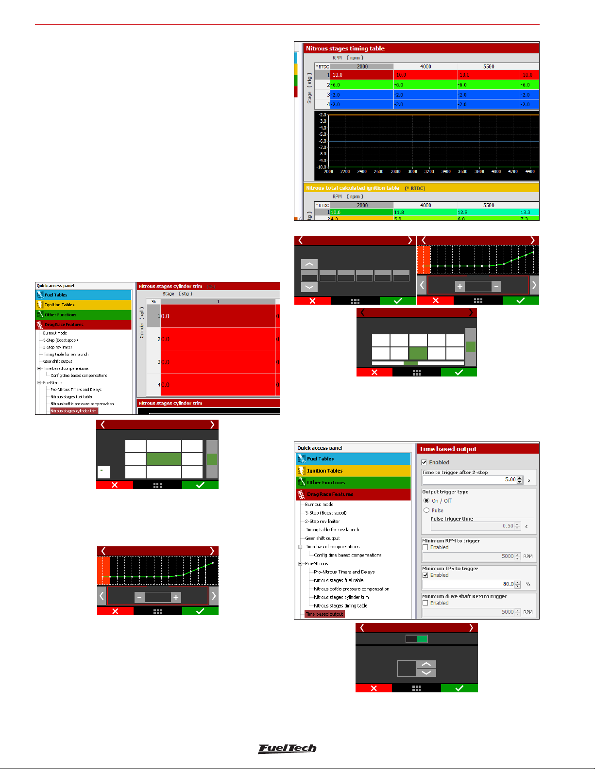
FT600
On the first screen is the configuration that allows setting a delay to
start the fuel compensation, based on the time that the nitrous shot
takes to get to the combustion chamber.
After the delay, there are the fuel tables to each stage. You can program
the fuel compensation over RPM and it is calculated considering the
main fuel table.
Since the injectors are closer to the combustion chamber than the
nozzles/foggers, the purpose is that the fuel and nitrous get to the
combustion chamber at the very same time.
In the FTManager software is possible to visualize the total calculated
fuel table.
It is possible to set an OFF delay and OFF ramp after each stage. It
helps because moments after shut down the nitrous solenoid, the intake
still full of nitrous that will be consumed by the engine.
Drag race features
Nitrous stage cylinder trim and bottle pressure
compensation
• This is a fuel injection cylinder trim for the Pro-Nitrous feature.
Pro-Nitrous cyl trim 1/2
Cylinders
1
1
-11,0-11,0-17,0
1
2
+1,0
+9,0
+3,0
+7,0 0,0
Stag.
3
• Bottle pressure compensation: compensates the bottle
pressure drop that happens in a run. The bigger the nitrous
consumption, the bigger the pressure drops, and consequently
the nitrous mass is smaller. With this, less fuel is necessary.
3
2
3
2
+
%
-3,0
-
Pro Nitrous fuel table 1/7
Delay to start fuel compensation
(in seconds)
2
1
0,30
0,25
0,2030,15
4
0,1050,10
Pro Nitrous fuel table 8/8
Time to deactivate fuel compensations
1
0,00
1,00
2
0,10
1,00
Delay
Ramp
6
Timing Pro-Nitrous stage 1 - 2/7
53
4
1,00
0,050,10
1,00
0,15
1,00
400 RPM
-2,75
+
[s]
-
º
20.9 Time based output
This feature allows activating an auxiliary output by time, which can
be used to release the parachute, turn on the nitrous or even switch
on the torque converter lockup solenoid.
Pro-Nitrous cyl trim 2/2
400 PSI
%
15
Nitrous stage timing tables: After the delay, there are the timing
tables to each stage. You can program the timing compensation
over RPM and it is calculated considering the main timing table. In
the FTManager software is possible to visualize the total calculated
ignition table.
92
Time based output 2/5
Disabled Enabled
Time to trigger after 2-step
5,00
s
Also, there are conditions, besides time, to trigger the output. The
conditions are: minimum RPM, minimum TPS, minimum driveshaft RPM
and minimum wheel speed.
Page 93
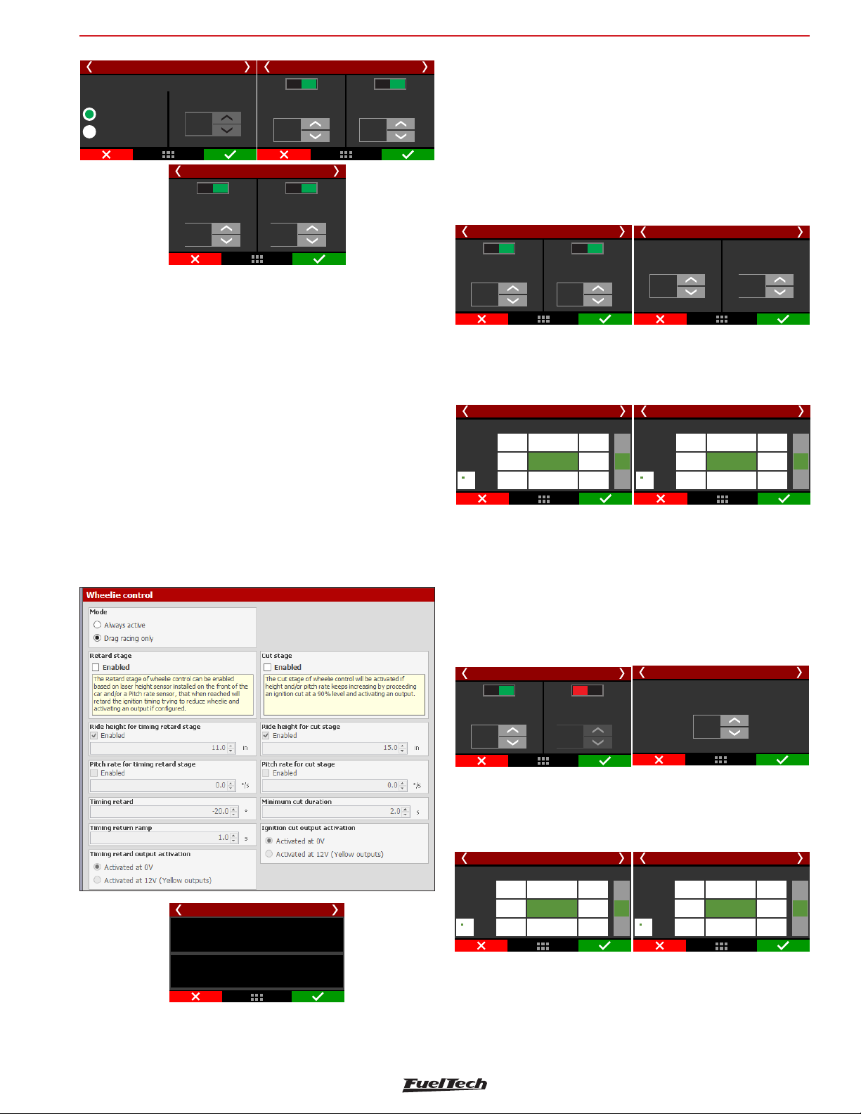
Drag race features
FT600
Time based output 4/5
MinimumtoRPM
trigger
5800
RPM
Minimum speed
to trigger
150
km/h
Enab.
Enab.
Disab.
MinimumtoTPS
90,5
%
Enab.
trigger
On / Off
One pulse
Time based output 3/5
Output trigger type
Pulse trigger
0,5
Disab.
Minimum driveshaft
5800
RPM
s
Time based output 5/5
Enab.
to triggerRPM
Disab.
Disab.
All these options can be enabled or disabled. The output signal can
be an ON/OFF signal (remaining on while the conditions are valid) or
a pulse (to release the parachute, for instance), which the duration
is programmable
The available activation conditions are: minimum RPM, minimum TPS,
minimum driveshaft RPM.
If the output trigger type is ON/OFF, when one of the conditions stops
being met, the output is turned off.
When activated, the output switches to 0V. In the FTManager, select
the output in the “Sensors and calibration” menu, then “Outputs”.
ignition to control the front height of the vehicle.
The retard stage is a first line of defense to keep the ride height under
control, the cut stage is a more aggressive way to stop the height/or
pitch rate from keep increasing.
Always active: As long as the engine is running this feature will be
active, independent how or where the car is positioned, even when
testing the car on a car lift. This function is highly recommended for
motorcycles.
Disab.
Height for timing
retard stage
11,0
in
Wheelie control 3/9
Enab.
Disab.
timing retard stage
Pitch rate for
5,0
°/S
Enab.
Timing retard
-10,0
°
Wheelie control 4/9
Timing return ramp
1,00
S
Drag racing only: This feature will be activated after releasing the 2
step button/switch, during the next 15s it will be operating.
Set height (in) or pitch rate (º/s) to activate the retard control. It is
possible to use both sensors at the same time.
Height compensation 36/
0,00
-0,80-0,88
15,0
16,0
-0,90
in
17,0
-0,88
se ndsco
0,10
-1,00
-1,00
0,20
-0,75
-0,88
-0,80
+
°
-
Pitch rate compensation 4/6
0,00
-0 80 -0,88.
250.0
300.0
-0,90
°/s
350.0
-0,88
se dscon
1.00
-1,00
-1,00
20.0
-0,75
-0,88
-0,80
+
°
-
20.10 Wheelie Control
This function reads height and pitch sensors to help prevent the from
leaving the track surface. It is recommended for rear wheel drive cars
and bikes.
Wheelie control
Retard stage
Cut stage
As the retarding control, there are height and pitch rate configurations
to the cut stage. The cut level can be configured, and it is possible to
define a minimum time to the cut occurs.
Always active: As long as the engine is running this feature will be
active, independent how or where the car is positioned, even when
testing the car on a car lift. This function is highly recommended for
motorcycles.
250.0
300.0
350.0
-0 80 -0,88.
-0,90
°/s
-0,88
Wheelie control 6/9
Minimum cut duration
2,00
S
Cut by pitch rate 4/7
se dscon
1.00
0,00
-1,00
-1,00
20.0
-0,75
-0,88
-0,80
+
°
-
Wheelie control 5/9
Disab.
Height for cut stage
15,0
in
Enab.
Disab.
Pitch rate for
cut stage
1,5
°/S
Enab.
Drag racing only: This feature will be activated after releasing the 2
step button/switch, during the next 15s it will be operating.
Set height (in) or pitch rate (º/s) to activate the retard control. It is
possible to use both sensors at the same time.
Cut by height 3/7
0,00
-0,80-0,88
15,0
16,0
-0,90
in
17,0
-0,88
se ndsco
-1,00
-1,00
0,10
0,20
-0,75
-0,88
-0,80
+
°
-
Cut stage
Retard Stage
This feature retards the ignition timing when the front of the car reaches
the limit height that has been programmed. The cut stage cuts the
There is also the option to trigger an auxiliary output when the retard
or cut is being performed. The output can be used to release the
chute, shift gears, etc.
In the FTManager, select the output in the “Sensors and calibration”
menu, then “Outputs”.
93
Page 94
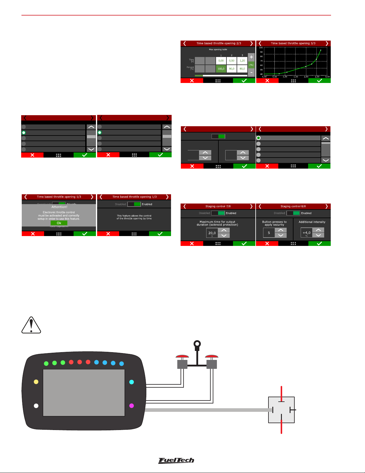
FT600
Drag race features
To use this function, a height sensor or a pitch rate sensor must be
installed and configured in the “Sensors and calibration” menu, then
“Inputs”.
20.11 Davis Technologies
The Davis Technologies Profiler is a traction control module, for rear
wheel drive cars, which controls ignition timing and ignition cut by
driveshaft RPM. This module allows direct communication with FT600.
In the FTManager, go to “Sensor and calibration” menu, then “Inputs”
and select the white input wires that will do the communicate with
the Davis Technologies Profiler.
Input selection
None
White 1: Avaliable
White 2: Avaliable
White 3: Air temperature
White 4: TPS
Timing signal 1/2
SmartDrop (TM) Signal 2/2
Input selection
None
White 1: Avaliable
White 2: Avaliable
White 3: Air temperature
White 4: TPS
20.12Time based throttle opening
This feature creates a curve for a time based progressive opening of
the electronic throttle.
You can create a curve based on time by maximum percentage of
throttle opening.
20.13 Staging control
This function helps the car alignment when pre-staging after the
burnout. When activated, it's possible to control the transbrake solenoid
frequency to hold the car properly.
Staging control 1/4
Disabled Enabled
Trans staging intensity
(each pulse reduction DC)
10,0
%
Frequency
(pulses per second)
15
Hz
Input selection
After configuring the inputs and outputs, its necessary to adjust the
safety parameters, like the number of button presses to apply security,
the additional intensity for security and the maximum time for output
duration for solenoid protection.
Staging control 3/4
None
White 1: O2 sensor
White 2: 2-step
White 3: Avaliable
White 4: Avaliable
Staging control electrical diagram with Hella solid state relay
Use the diagram below to wire the staging control feature.
Any white wire can be used for the 2-step and staging buttons. The other side of the buttons must be connected to the battery negative or
to a switched 12V when needed.
IMPORTANT:
The use of a solid state relay is mandatory for this feature to work properly.
ground
or 12V
Staging
Button
White wire
White wire
Blue, Gray or Yellow wire
2-Step /Transbrake
Button
Ground
Activation
+12V to load/transbrake
87
85
86
Switched power
12V ee(us fus )
Do not
Connect
30
Solid State Relay
Hella
94
Page 95
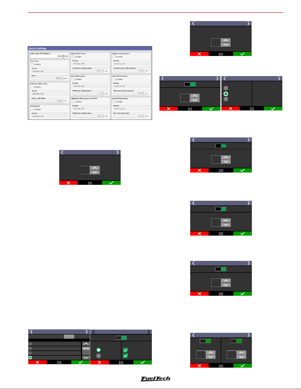
Alert settings
FT600
21. Alert settings
This is the menu where you can set all the alert warnings, including
safety mode and engine shut down.
21.1 Safe mode RPM limiter
Safe mode protects the engine whenever an alert is activated, limiting
max engine RPM while the alert condition is still happening.
Safe mode limiterRPM
Safe mode limiterRPM
Shift light 3/3
Turn on shift light
with RPM above
6500
RPM
Over rev
Setup the RPM for alert and the action the ECU must perform.
Disabled
Over Rev 1/2
Over Rev Alert
6000
RPM
Enabled
Alert only
Safe Mode
Engine shutt off
Over Rev 2/2
The Alert will appear only
on the Ft500 display.
The engine will enter
Safe mode with defined
Rev limiter.
Overboost
Setup an overboost value to activate the alert and the action the ECU
must perform.
Overboost 1/2
Disabled
Overboost alert
3,50
bar
Enabled
3000
RPM
21.2 Alerts
The configuration of alerts allows the programming of sound and
visual alerts whenever a dangerous situation to the engine is detected.
It is possible to setup up to three different actions when any alert is
displayed on the screen:
Alert only: alert is displayed on the screen, but the engine continues
to work normally.
Safe mode: besides the alert displaying on the screen, engine has its
max RPM limited to what was set up on the “Safe mode rev limiter”
parameter
Engine shut off: besides the alert displayed on the screen, engine
is immediately shut off by fuel and ignition cut.
Shift alert
When engine reaches the RPM set on this parameter, an alert can be
shown at the dashboard and/or an auxiliary output can be activated
to control an external shift light.
Engine temperature
Setup an engine temperature to activate the alert and the action the
ECU must perform.
Engine Temperature 1/2
100
Enabled
°C
Disabled
Engine temperature alert
Injector duty cycle
Setup a percentage value that indicates injector’s saturation.
Injector duty cycle 1/2
Disabled
Injector duty cycle alert
Enabled
90
%
Oil Pressure
Enter a value that would be considered as excessive oil pressure
excess and one that’s considered for low oil pressure. Also, select
how the ECU reacts when this alert is activated.
Shift Alert 1/2
Test output:
None
Blue 7: Fuel pump
Blue 8: Electric fan #1
Gray 5: Available
Output selection
Test
Shift light 2/3
Disabled Enabled
RPM settings
Single value
Each gear
Output options
Dashboard
Output pin
Oil Pressure 1/2
Disab. Enab.
Low oil pressure alert
1,50
bar
Disab. Enab.
High oil pressure alert
5,00
bar
95
Page 96
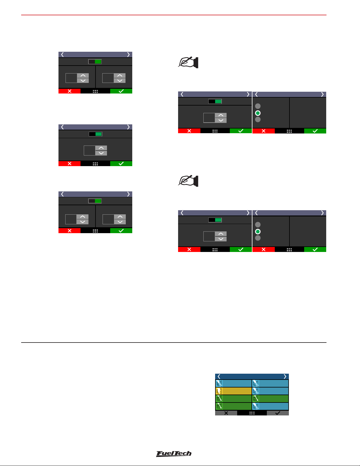
FT600
Alert settings
Minimum oil pressure
Setup a minimum oil pressure value above X RPM and how the ECU
reacts.
Minimum Oil Pressure 1/2
Disabled
Minimum Oil Pressure alert
3,00
bar
Enabled
when above:RPM
5500
RPM
Low fuel pressure
Setup a value to activate the alert and how the ECU reacts.
Low Fuel pressure 1/2
4,40
bar
Enabled
Disabled
Low Fuel pressure alert
Base fuel pressure
Setup here a tolerance for the base fuel pressure.
Base Fuel pressure 1/2
Disabled
Base Fuel pressure Allowed range
1,50
bar
The base fuel pressure is what the pressure regulator should keep with
MAP = 0 psi, that, in most of cases is 45psi with the engine turned
off and the fuel pump turned on.
Enabled
0,20
bar
High exhaust gas temperature alert (EGT)
Set the high exhaust gas temperature value for alert and the alert type
as: “Alert only” “Safe mode” or “Engine shut off”.
NOTE:
This function only works for EGT probes reading a
single cylinder. EGTs for the entire bank or a single
EGT for the motor are not considered for this alert.
Exhaust gas temp. High EGT 1/2
Disabled Enabled
Alert
Exhaust gas temp. high (EGT)
800
ºC
Exhaust gas temp. High EGT 2/2
Warning only
Safe mode
Engine shut off
The alerts will be validated
of problem condition and
after 2 seconds of engine
running to prevent false
after 0.1 second
they will be chacked
triggering after start.
Low exhaust gas temperature alert (EGT)
Set the low exhaust gas temperature value for alert and the alert type
as: “Alert only” “Safe mode” or “Engine shut off”
NOTE:
This function only works for EGT probes reading a
single cylinder. EGTs for the entire bank or a single
EGT for the motor are not considered for this alert.
Exhaust gas temp. Low (EGT) 1/2
Disabed Enabled
Alert
Exhaust gas temp. low (EGT)
100
ºC
Exhaust gas temp. Low EGT 2/2
Warning only
Safe mode
Engine shut off
The alerts will be validated
of problem condition and
after 2 seconds of engine
running to prevent false
after 0.1 second
they will be chacked
triggering after start.
When engine is turned on, the vacuum/boost makes the fuel pressure
regulator to manage the fuel pressure in a 1:1 ratio.
Example: an engine idling with -8.7psi of map pressure must have
34.8psi of fuel pressure if differential pressure is set as 43.5psi. If
the MAP sensor is reading 29psi, the fuel pressure must be 72.5psi.
If the tolerance range is 5.8psi, the differential pressure can vary from
37.7 psi to 49.3psi.
22. Favorites
In this menu it is possible to have access to the most used functions
of the ECU. It gives quick access to functions as:
Main fuel
injection table
Main ignition
table
Iddle speed
control settings
Internal
datalogger
Favorites
Accel fuel enrich
and decay
Engine
start
Two step
rev. limiter
Overall
fuel trim
96
Page 97
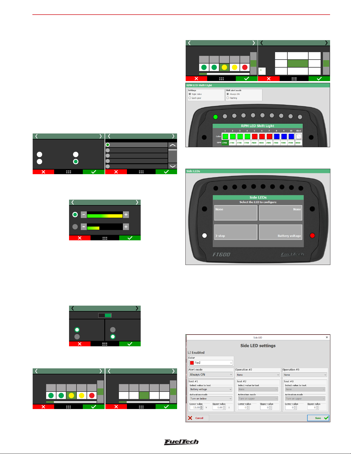
Interface settings
FT600
23. Interface settings
Here are the settings related to the interface like measure units, buzzer
sound, LCD backlight, etc.
23.1 Day/night mode selection
There are 4 options to select.
Day mode: adjust brightness the display to value in LCD backlight
settings menu.
Night mode: adjust brightness the display to value in LCD backlight
settings menu.
Dashboard: Enable button on dash to control mode.
Day/night external switch: this option is necessary configure a white
input with vehicle light switch.
Day/night mode selection 1/3
Selection
Day mode
Night mode
Dashboard
Day/night
external switch
23.2 LCD blacklight settings
Day/night mode selection 2/3
Input selection
None
White O2 General1:
White 2: 2-step
WhiteiCtioning3: Ar ondi
WhiteOil pressure4:
By gear: select the LED to edit, choose its color, set the RPM you
want it to turn on for each gear and which LEDs will be activated.
2
5000 6000
1
2
5200
3
5300
LED bar 3/3
LED
3
6200
6300 7300
7000
7200
4
+
RPM
-
Color
LED bar 2/3
LEDfor Colors
Led
1
3
2
4
+
5
[RPM]
Gear
-
Side LEDs
It Is possible to set side LEDs choosing from up to 52 alerts options.
Adjust LCD brightness and select between night and day modes.
LCD Backlight settings
Day Mode
100%
Nigth Mode
36%
23.3 LED configuration
This function allows you to configure all optional LED’s
LED bar
Select here the options on how the shift light LEDs will work. It is
possible to set the LEDs to turn on in a fixed RPM, progressively or
with different values by gear.
LED bar 1/3
Disabled Enabled
Operation mode
Single value
Each gear
Single value: select the LED you want to edit, choose its color and
the RPM value to activate it .
LED bar 2/3
LEDfor Colors
+
5
[RPM]
Color
Led
1
3
2
4
Alert mode
Always enabled
Blinking
LED bar 3/3
LEDfor Color
Led
1
Color
-
3
6000
4
7000 8000
2
50004000
+
5
[RPM]
-
Color: Select the LED color.
Warning mode: This menu has two options; always enabled or
blinking;
Condition: Select the function will be associated to this LED.
Activation mode: set the maximum and minimum values to turn the
LED on.
Operation 2 and 3: This option provides more activation conditions
to the same LED.
97
Page 98
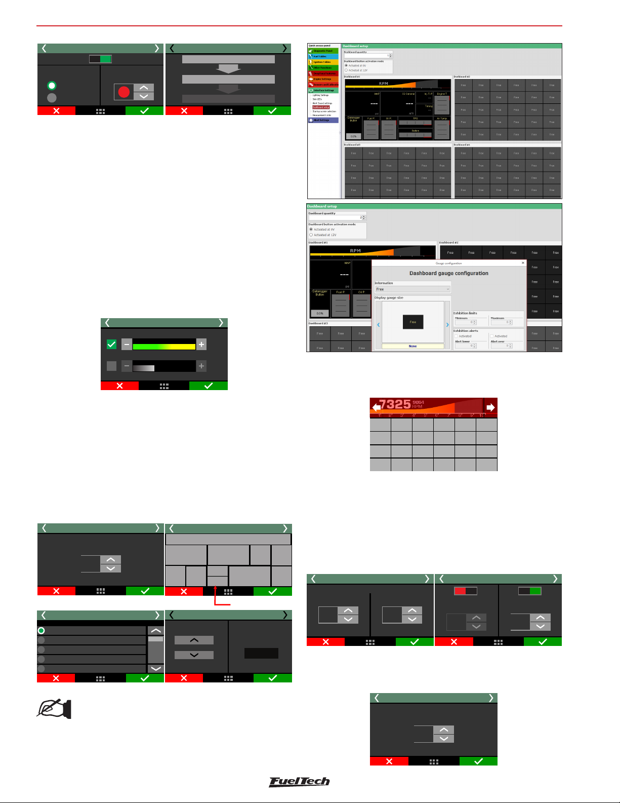
FT600
17
Interface settings
Side LEDs 2/7
Disabled Enabled
LED mode
Always enabled
Blinking
Co rlo
1.
2.
3.
Side LEDs 3/7
Battery
and
RPM
Avaliable
LCD blacklight settings
Adjust LCD brightness side LED’s and select between night and day
modes.
LEDs Testing
This option verify if all LEDs are working properly. Selecting this function
the LEDs must to turn on with the same color and at the same time, in
case any LED do not turn on you must get in contact with FuelTech
maintenance sector.
23.4 Alert sound settings
This parameter allows for setting the volume of sounds generated by
touching the display. When the mute option is selected, the ECU is
silent when the screen is touched.
Alert Sound settings
Interface sound volume
100%
Alerts sound volume
36%
23.5 Dashboard setup
There are 96 configurable positions on the dashboard, with minimal
size of 1x1. It’s possible to select sizes as 1x2, 2x1, 2x2, 3x2 and 3x1.
First, select the position where you want the information to be, then
the reading that will be displayed and the reading size.
Dashboard setup is very simple, first select the number of dashboards
you want (1 to 4), after that set the space will be used, and then,
choose the information you want and select right to define the gauge
size.
Dashboard setup 1/7
Dashboard quantity
4
Information select:
Display configuration 2/5
TPS
MAP
O2 Sensor #1
Oil Pressure
Fuel Pressure
NOTE:
After version 3.10 of FTManager is possible to set 4
different dashboards directly in the software clicking
over the free gauges and editing the informations.
Data
Dashboard setup 3/7
MAP
P.Comb
Display configuration 3/5
Size exhibit
RPM Bar
Lambda 1
Free
Free
Battery
Available
Ignition
Dado (1x2)
Alvo WG
0.00
T.Engine
TPS
Clicking in the upper corners of the touchscreen the other configured
dashboards will appear, as illustrated below, or it is also possible to
set a white input as a button/switch key to change the dashboards.
9864
7325
RPM
234568910
Exit
Exhibition limits and alerts
On some sensors, maximum and minimum values may be set up to
activate alerts on the dashboard. In this case, the sensor changes it’s
color to indicate something is wrong. The sensors readings with these
options are: MAP, air temperature, engine temperature, battery voltage,
fuel pressure, oil pressure, TPS, dwell, ignition timing, primary injection
time, secondary injection time, O2 sensor 1, O2 sensor 2 and delta TPS
Display configuration 4/5
Exhibition limits
Minimum
-40
°C
Maximum
+150
°C
Display configuration 5/5
0
°C
Disab. Enab.Disab. Enab.
Alert over:Alert lower:
98
°C
RPM bar
When clicking the RPM bar parameter, it is possible to setup the RPM
where the red zone starts.
Display configuration
Red zone RPM
5500
RPM
98
Page 99
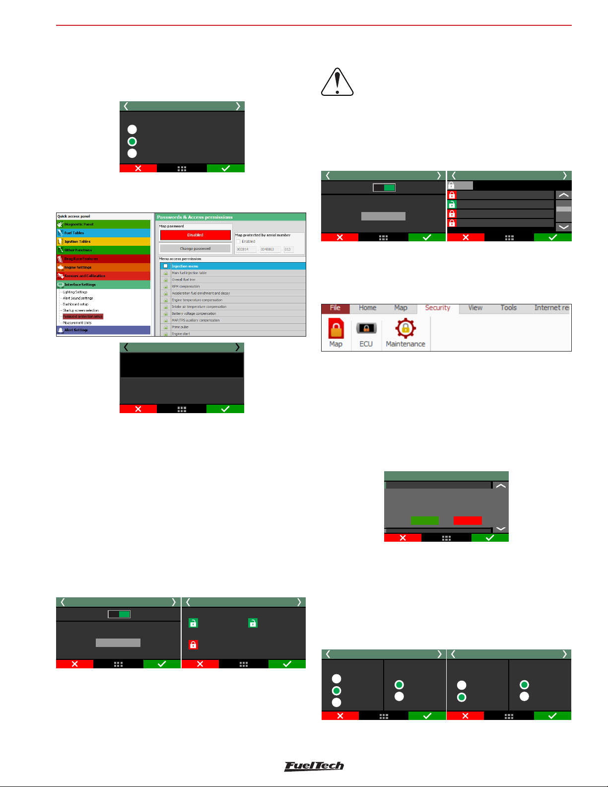
Interface settings
FT600
23.6 Startup screen selection
Select the screen shown right after the ECU is turned on. In case the
option “Open the main menu after startup” is selected and the ECU is
set up with a user password, the ECU will ask for the user password.
Startup screen selection
Open the main menu after startup
Open the dashboard after startup
Open the favorites menu after startup
23.7 Password Protection setup
It is possible to set 2 different kinds of password:
The FTManager software access is also blocked by the Map password.
WARNING:
Passwords come disabled by default, when you
enable a password you will be blocking access to
people using the ECU, even yourself. When you
choose a password, be sure you will remember
it, as for safety reasons this password will only
be removed through the total reset of the ECU
(all maps and data are erased).
Password protection setup 1/9
Disabled
Change password
Enabled
Map password
Password protection setup 2/9
Injection menu
All
Main fuel injection table
Overall fuel trim
RPM compensation
O2 closed loop
Maintenance Password
This password only used to block editing Odometer and Houmeter.
Password protection setup
ECU
MAP
ECU Password
Activating the ECU password allows three types of blocking protection:
• FTManager: choose this option to activate an FTManager access
password, but keep all touchscreen menus accessible. Do this to
avoid that a password being activated without your consent.
• Menus: This option protects all the ECU menus, only giving access
to information displayed on the on board computer and engine
status.
• Engine Start: Engine start blocking. All menus will be available
for viewing and editing, but the ECU system will be blocked until
the password is inserted.
Password protection setup 1/2
Disabled
Change password
Enabled
ECU password
Password protection setup 2/2
Menus
Engine
Start
FTManager
Map Password
This password blocks all the map menus of the fuel and ignition table
adjustments, engine settings, aux function and file manager. Alert
settings, shift alert, display and initial screen are left unprotected.
When this password is enabled, it’s not possible to change any ignition
or fuel maps.
23.8 Clear peaks
At the Dashboard, values read by the sensors connected to the module
are displayed in real time. On the bottom of each box on the display,
the minimum (on the left) and maximum (on the right) values read
by the sensor are shown.
It is possible to clear this data by accessing the option “Clear Peaks”,
under the “Interface Settings” menu.
Interface settings
Clear peaks
Configuração do painel de instrumentos
Seleção da tela principal
Configuração de favoritos
Configuração de favoritos
Warning!
Are you sure you want
to clear peaks?
Yes
No
23.9 Measurement units
In this menu it is possible to change the measurement unit for some
parameters as pressure, temperature, speed and O2 readings.
Pressure Units: bar, PSI or kPa;
Temperature units: °C or °F;
O2 sensor units: Lambda, AFR Gasoline or AFR Methanol;
Speed units: km/h or mph
Measurement Units 1/2
Pressure unit
bar
Psi
kPa
Temperature unit
°C
°F
Measurement Units 2/2
O2 Sensor unit
Lambda
AFR
Speed unit
kph
mph
99
Page 100
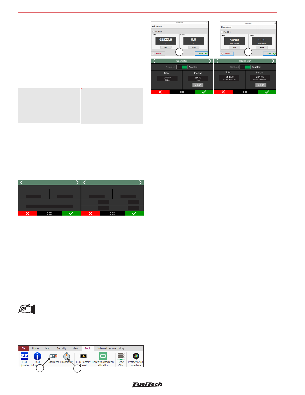
FT600
23.10 Demonstration mode
The demonstration mode can be enabled to show the main features
of FuelTech FT600 and its working. You can set the waiting time to
get in the demo mode. To exit, just touch the screen.
23.11 Touchscreen calibration
This function allows the touchscreen re calibration, use it whenever
you notice the screen is unresponsive. Calibrate the screen with you
finger or with a pen.
IMPORTANT
Now touch screen calibration
will be perfomed. Touch points
at the positionsEXACTLY
shown by arrows.
Touch screen to continue!
CALIBRATION
3 touches left
23.12 Serial number and software version
In this menu, it is possible to verify the software version and the
equipment’s serial number.
Interface settings
1 2
Make sure you have these numbers in hand whenever the FuelTech
Technical Support is contacted to facilitate and optimize the assistance.
Serial number and version 1/2
Software Version
General
version
1.00
Serial number
002814.0023041.035
Compatibility
version
1.00
Serial number and version 2/2
Software Version
General
version
1.00
2.00
ECU:
1.00
Interface:
Compatibility
Bootloader:
Bootloader:
version
1.00
1.00
1.00
23.13 Odometer and Hourmeter
This function was speciallyu designed for engines that require a milage
or timing control.
1 - Odometer: Inser the mileage of the vehicle in the “total” field,
this value can be eddited only through the FTManager with the
specific password, there is a “Partial” odometer that is possible
to zero the value anytime.
2 - Hourmeter: Follows the same principle of the Odometer,
registering the engine hours in the “Total” field, having another
field for “Partial” hours.
NOTE:
These values are saved in the FuelTech memory,
independently of the map that is active. The values can
only be changed through the FTManager and through
a previously configured password.
100
1
2
 Loading...