

Fuelab 52901 User Manual
Model Number 52901-c
Electronic Fuel Pressure Regulator
Operating and Inst allation Instruc tions
This Product is protected under one or more of the following patents: US 7,810,470
CCAAUUTTIIOONN!!
This product is to b e installed only by persons knowledgeable in the repair and modification of vehicle fuel systems
and general vehicle systems m odi fication. Only a qualified technician or mechanic who is aware of applicable
safet y procedures should perfor m the installation of this product.
GASOLINE AND OTHER FUELS ARE FLA MMABLE AND CAN BE EXPLOSIVE!
Perform the installati on in a well venti l ated location only to minimize the bui l d up of fuel vapors. NO op en flames,
smok ing or other sources of ignition are to be present during install at ion, to prevent fire or explosion that can cause
serious inju ry or death. Grinding, cutting, and drilling must be performed with care to prevent ignit ion. Draining and
removal of all fuel and ventilation of vapors in vehicle and fuel system is recommended when performing such
procedures. Proper e ye and personal protection is required at all ti m es durin g installat ion.
WWAARRNNIINNGG!!
The Ve hi cle’ s fuel system may b e under pressur e! Do not lo osen any fuel connections until relieving all fuel system
pr essure. Consult an applicable servic e manual for instru ct io ns to relieve f uel system pressur e safely.
This product is intended for racing, off-road, or mari ne use only. This fuel system component may not be legal for
sale or use on emission controll ed motor vehicles; consult local, state and national laws.
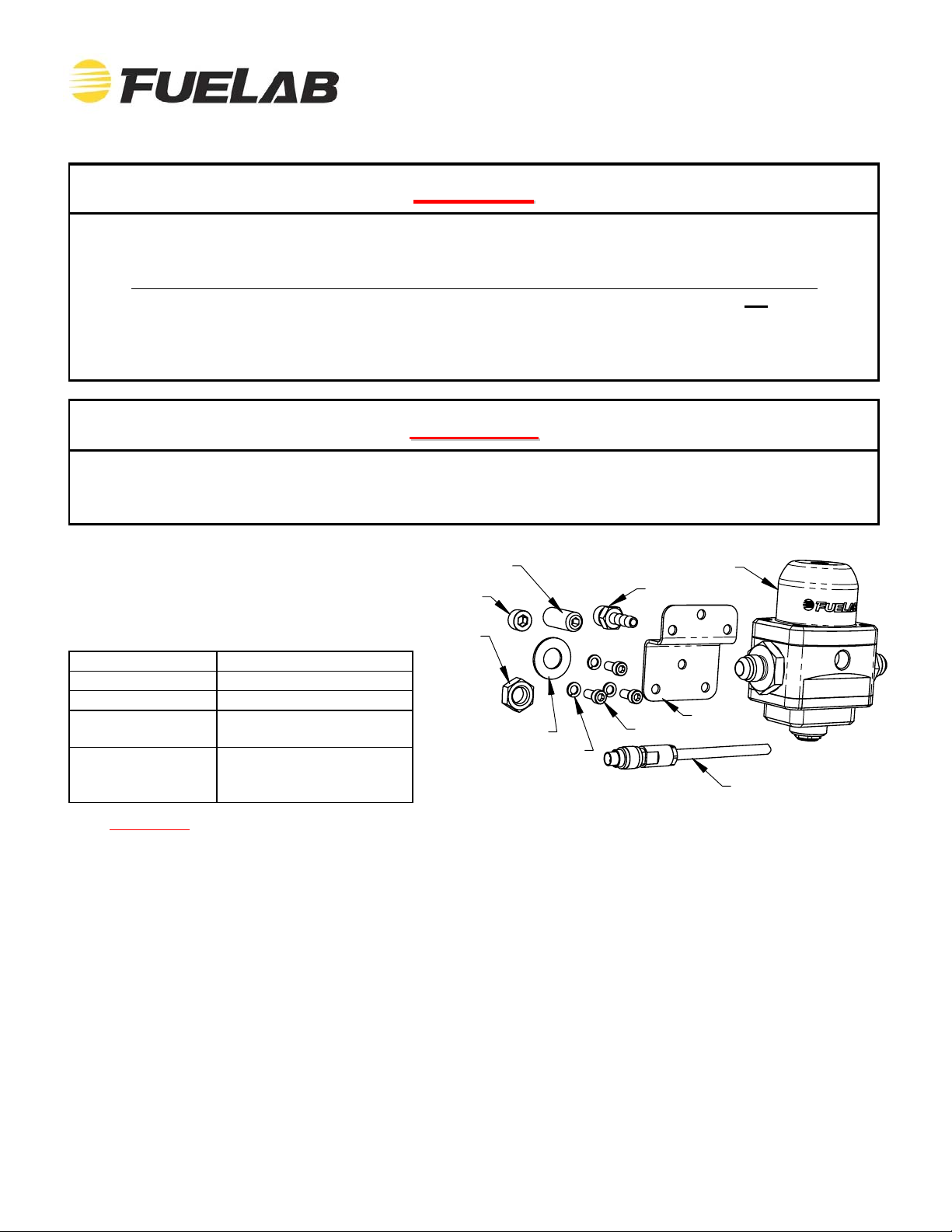
Pr oduct C ont ent s :
Check the diagram and list of components
( ri ght) to ensure that no components are
missing from box. Contact your Fuelab
distributor immediately for replacement.
52901-c Features and Performance Ratings:
Fitting Sizes -6AN Male Fitting
Seat Size Standard
Operating Voltage 8-18 Volts DC
Maximum Flow
Capacity
Pressure
Adjustment Range
6.3 GPM at 35 PSID
(1440 LPH at 2.4 Bar)
Pressure Range “E”
25-90 PSID
(1 .75-6.2 Bar)
Adjustment Screw
Plug
Jam Nut
Flat Washer
(3X) Bracket Lock Washers
Electronic Regulator
Barbed Fitting
Bracket
(3X) Bracket Screws
Electrical Plug and Wire
WARNING! Exce eding maximum flow capacity may result in an o ver-pressur e operating conditi on.
Before Installation, Plan Entire Fuel System:
These instr uctions are li m i ted to general topics of regul ator component install ation and may n ot include specifi c
inf orm ation pertai ning to your application. These instruct ions are written assuming the use of a Fuelab Prodigy
Electroni c Fuel Pump. T hi s regul ator is ONLY compat i ble with Prodigy Fuel Pumps (Prodigy Models 41401-c,
41402-c , 41403-c, 42401- c and 42402-c, no t compatible with Prodigy Models 41404-c, 4 0401-c and 40402-c). T hi s
r egulato r has an int ern al spring that can be changed for other pressure ranges, includ ing “G” range, for 90-125
PSID if required by the specific application. Lower, carbureted pressure ranges are recommended for a different
model of regulator only. Visit our company web site for specific details pertaining to example fuel syste ms and other
solut io n ideas. Addi tional inform ation including advanced tr oublesho oting, any special alerts and FAQ’s pertaining
to this and other products is also available.
General Regulator Performance Notes:
The notat ion “PSIG” m ean s pressure in Pounds per Square Inch (PSI) relative to the prevailing atmospheric
condition or outside air. This is referred to as Gauge P ressure. The notation “PSID” means pressure in PSI relative
to another pressure source or called the Diffe rential Pressure. The intake manifold pressure, when plumbed to the
reg ulator, changes the fuel pressure in a 1:1 ratio. Wh en the engine idles (for example 12 Inches of Mercury or 6
PSIG of vacuum) fuel rail pressure will lower 6 PSI, when compared to the set ting with the engine off. F or boost e d
applications, including turbo or superchargers, fuel rail pressure increases at a 1:1 ratio. An engine at 10 PSIG of
boost as measured in the intake manifold, will increase the fuel pressure by 10 PSIG.
109020121-1, No Rev Sheet 1 of 6
Plumbing Planni ng Notes:
”
p
Minimize plumbing restrictions between fuel rail(s) and regula tor for peak performance, use –6AN (3/8”) to –10AN
(5/8”) line as required per flow rate requirements of the vehicle’s engine and fuel pump. EFI applications can use a
“Y” block or “T” fitting to spl i t the output of the fuel pump i n t o one end of each fuel rail (for dual fuel rail application)
then plumbed into the singl e inlet port. Use of a –6A N (3/8”) return line is typicall y recommended for this model of
regulator. See diagram on next page as well as diagram below, to identify the ports used on the regulator. The fuel
line used must handle hi gh pressure. The use of fuel line such as stainless steel braided line and “AN” style fitt in g
connections is recommended. The fuel ports (one –6 AN In le t Po rt and one –6AN R e tu r n Po r t) use “AN” or “militar y
style fitt ings. This plumbing standard is commonly used with racing and h igh performance applic ations. See step 6
on next page for additional information on this port standard. A fuel filter with a 60 micron or lower particle rating is
required to be used upstream of regulator and downstream from fuel pump to protect it and the fuel injectors from
foreign object damage. Ref erence the Schematic Diagram below f o r filter locations. Use of a liqui d fil l ed gauge
exposed to engine compartment heat is not recommended as the l iqu id inside the gauge may exert measur ement
error s. DO NOT
plumb gauge port to any gauge mounted inside the vehicle or in passenger compartment. A line
burst can spi l l fuel inside passenger compartment and on occupants, possibl y causing serious injury or death. An
electric gauge or pressure transducer system is recommended for readings in a pass e nger compartment.
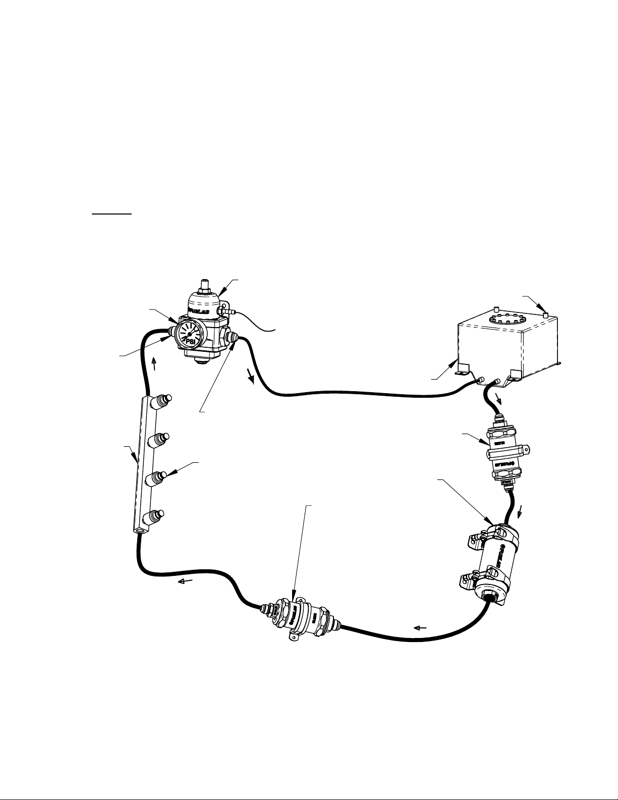
Typical EFI Fuel System Schematic Diagram:
Fuel Gauge Shown in
Gauge Port, Liquid Fille d
Gauge may have Error Due
to Temperature Variations.
Inlet Fitting
on Left Side
52901-c Regulator
To Engine Intake Manifold
Specifications and Recommendations.
Follow Fuel Cell Manufacturer's
Recommendations for Proper
Vented Fuel Cell or Fuel Tank.
Tank must be Plumbed According
to Maximum Pump Flow Rate.
Consult Pump Manufacturer's
Cell Vent Plumbing
with Injectors
Fuel Rail
Return Fitting
on Right Side,
DO NOT REMOVE!
Multiple Rails can be plumbed
using "T" Fitting or "Y" Block.
Dual Inlet Regulator is Not
Required, as Changes in
Flow Rate through
Regulator are Very
Small when Compared
to other Bypass Style
Regulators.
Fuel Straining Filter Required, Typical
Micron Rating: 75-150, Fuelab
75 Micron Filter Recommended.
Fuelab Prodigy Series
Fuel Pump REQUIRED!
(Regulator Accepts Up
to Two Prodigy Pumps)
Fuel Filter with 60 Micron or
Lower Particle Rating is Required.
Fuelab Filter with 6, 10 or 40
Micron Rating is Recommended.
Check Valve Required for Reduced
Vehicle Emissions and Improved
Engine Starting. Fuelab 848xx
and 858xx Series Filter has Check
Valve Assembly Built in.
Ins t a lla t ion Steps :
1. Disconnect the grou nd terminal from battery and allow the vehicle’s engine and exhaust system to cool.
Relieve fuel system per applicable service manual. Follow all Warnings and Cautions written on previous page
of these instruct ions .
2. Modify, remove or replace other fuel system components as required per establis hed build plan ( refer ence
notes on previous page and above).
3. Use the supplied bracket as a drilling te mplate to mark holes for mounting bracket. Choose a location that
minimizes exposure to excessive heat, near fuel rails. Mounting bracket can be modified as required. Use
clear or colored enamel
aint to protect bracket surface af ter any modification.
109020121-1, No Rev Sheet 2 of 6
 Loading...