

Page 1
Model Number 56502-c
Fuel Pressure Regulator
Operating and Installation Instructions
CCAAUUTTIIOONN!!
This product is to be installed only by persons knowledgeable in the repair and modification of vehicle fuel systems
and general vehicle systems modification. Only a qualified technician or mechanic who is aware of applicabl e
safety procedures should perform the installation of this product.
GASOLINE AND OTHER FUELS ARE FLAMMABLE AND CAN BE EXPLOSIVE!
Perform the installation in a well ventilated location only to minimize the build up of fuel vapors. NO open flames,
smoking or other sources of ignition are to be present during installation, to prevent fire or explosion that can cause
serious injury or death. Grinding, cutting, and drilling must be performed with care to prevent ignition. Draining and
removal of all fuel and ventilation of vapors in vehicle and fuel system is recommended when performing such
procedures. Proper eye and personal protection is required at all times during installation.
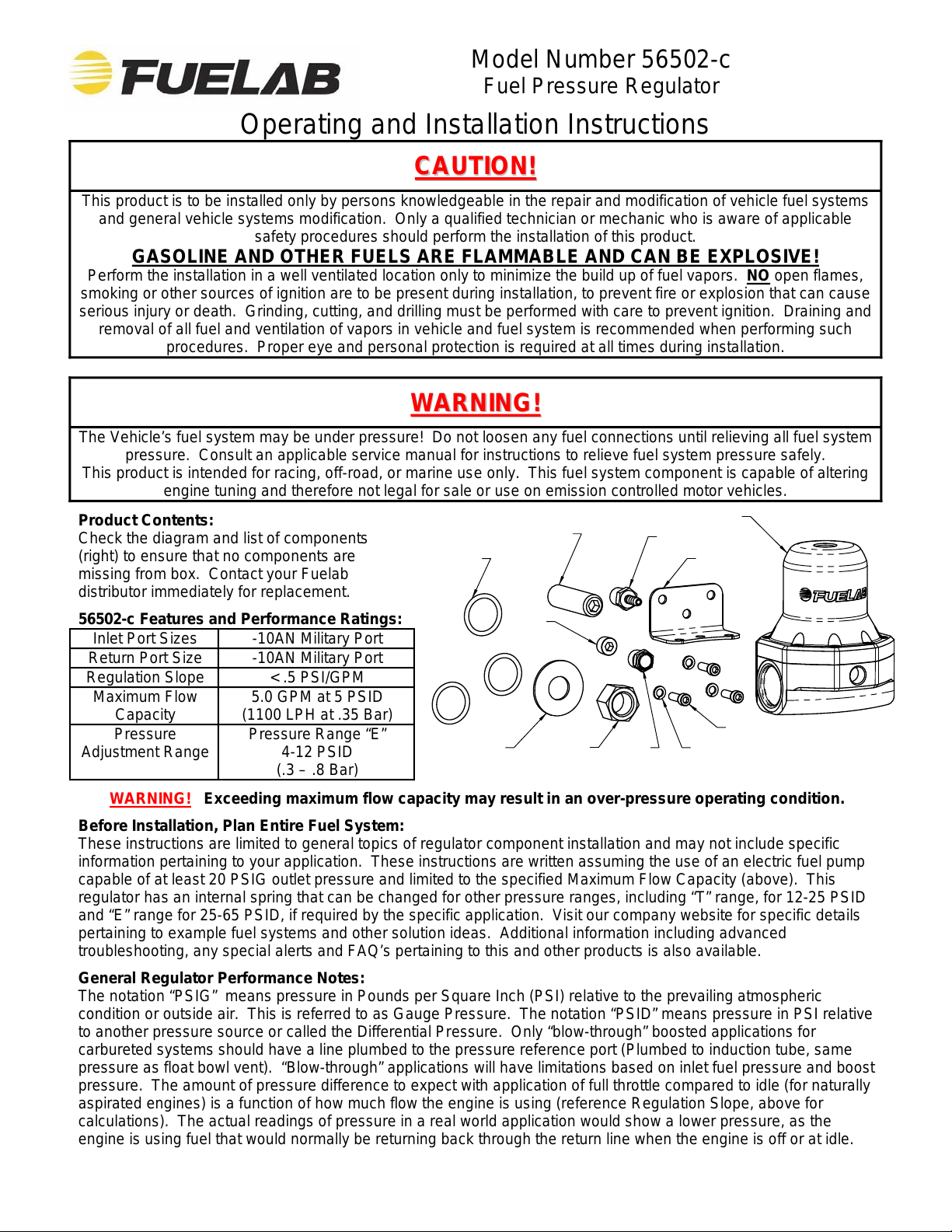
Plug
Jam Nut
Filter
Regulator
Barbed Fitting
Bracket
(3X) Bracket Screws
(3X) Bracket Lock Washers
WWAARRNNIINNGG!!
The Vehicle’s fuel system may be under pressure! Do not loosen any fuel connections until relieving all fuel system
pressure. Consult an applicable service manual for instructions to relieve fuel system pressure safely.
This product is intended for racing, off-road, or marine use only. This fuel system component is capable of altering
engine tuning and therefore not legal for sale or use on emission controlled motor vehicles.
Product Contents:
Check the diagram and list of components
(right) to ensure that no components are
missing from box. Contact your Fuelab
distributor immediately for replacement.
56502-c Features and Performance Ratings:
Inlet Port Sizes -10AN Military Port
Return Port Size -10AN Military Port
Regulation Slope < .5 PSI/GPM
Maximum Flow
Capacity
Pressure
Adjustment Range
5.0 GPM at 5 PSID
(1100 LPH at .35 Bar)
Pressure Range “E”
4-12 PSID
(.3 – .8 Bar)
(3X) -910 O-ring
Adjustment Screw
Flat Washer
WARNING! Exceeding maximum flow capacity may result in an over-pressure operating condition.
Before Installation, Plan Entire Fuel System:
These instructions are limited to general topics of regulator component installation and may not include specific
information pertaining to your application. These instructions are written assuming the use of an electric fuel pump
capable of at least 20 PSIG outlet pressure and limited to the specified Maximum Flow Capacity (above). This
regulator has an internal spring that can be changed for other pressure ranges, including “T” range, for 12-25 PSID
and “E” range for 25-65 PSID, if required by the specific application. Visit our company website for specific details
pertaining to example fuel systems and other solution ideas. Additional information including advanced
troubleshooting, any special alerts and FAQ’s pertaining to this and other products is also available.
General Regulator Performance Notes:
The notation “PSIG” means pressure in Pounds per Square Inch (PSI) relative to the prevailing atmosp heric
condition or outside air. This is referred to as Gauge Pressure. The notation “PSID” means pressure in PSI relative
to another pressure source or called the Differential Pressure. Only “blow-through” boosted applications for
carbureted systems should have a line plumbed to the pressure reference port (Plumbed to induction tube, same
pressure as float bowl vent). “Blow-through” applications will have limitations based on inlet fuel pressure and bo ost
pressure. The amount of pressure difference to expect with application of full throttle compared to idle (for naturally
aspirated engines) is a function of how much flow the engine is using (reference Regulation Slope, above for
calculations). The actual readings of pressure in a real world application would show a lower pre ssure, as the
engine is using fuel that would normally be returning back through the return line when the engine is off or at idle.
105020622-1, No Rev Sheet 1 of 4
Page 2
Plumbing Planning Notes:
Minimize plumbing restrictions between carburetor(s) and regulator for peak performance. Use –8AN (1/2”) to
–10AN (5/8”) line as required per flow rate requirements of the vehicle’s engine and fuel pump. See company web-
site for nitrous oxide use and alternate plumbing schematics. See diagram on next page as well as diagram below,
to identify the ports used on the regulator. Plumb the return line back to the fuel tank. Use of a –8AN (1/2”) or -
10AN (5/8”) return line is typically recommended for this model of regulator. Plumb the Pressure Reference Port
using the barbed fitting for “blow-through” carbureted applications only, “blow-through” means that a turbo o r
supercharger is used to pressurize the carburetor(s). When this occurs, fuel pressure must be compensated by the
change in float bowl pressure. If motor is naturally aspirated (Normal carbureted application, with float bowl vented
to atmosphere) allow this port to vent to atmosphere, do not plug or plumb to any pressure source. Use of supplied
port filter is shown below. The fuel line used must handle high pressure. The use of fuel line such as stainless
steel braided line and “AN” style fitting connections is recommended. The fuel ports (two –10AN Inlet/Outlet Ports
and one –10AN Return Port) use “AN” or “military” style fittings. This plumbing standard is commonly used with
racing and high performance applications. See step 6 on next page for additional information on this port standard.
A fuel filter with a 40 micron or lower particle rating is required to be used upstream of regulator and downstream
from fuel pump to protect it and the carburetor from foreign object damage. Reference the Schematic Diagram
below for filter locations. Use of a liquid filled gauge exposed to engine compartment heat is not recommended as
the liquid inside the gauge may exert measurement errors. DO NOT
plumb gauge port to any gauge mounted
inside the vehicle or in passenger compartment. A line burst can spill fuel inside passenger compartment and on
occupants, possibly causing serious injury or death. An electric gauge or pressure transducer system is
recommended for readings in a passenger compartment.
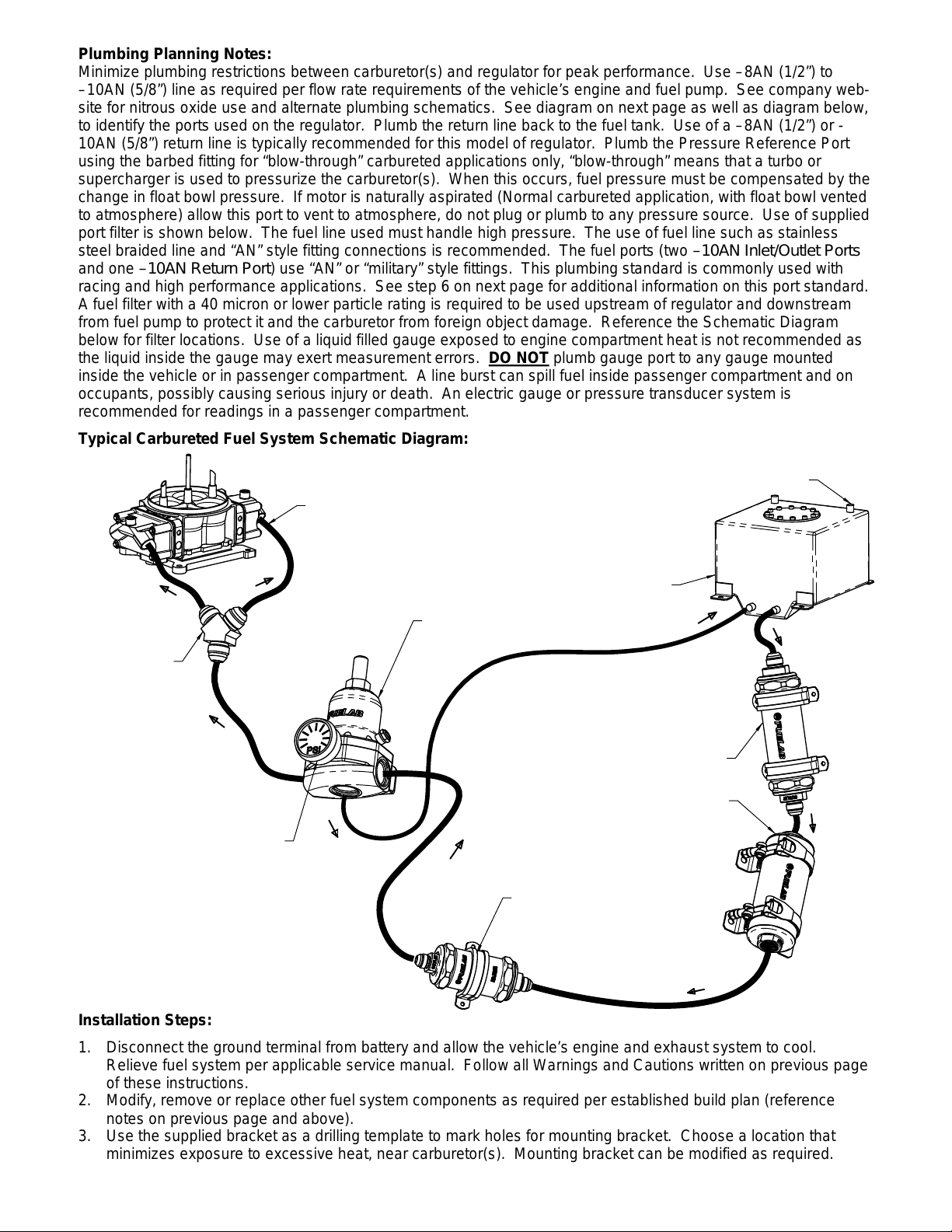
Typical Carbureted Fuel System Schematic Diagram:
Typical Dual Inlet
Carburetor Shown
Y-Block or Fuel Log,
to Split Flow into
Multiple Fuel Bowls
56502-c Regulator
Fuel Gauge Shown in
Gauge Port, Liquid Filled
Gauge may have Error Due
to Temperature Variations.
Follow Fuel Cell Manufacturer's
Recommendations for Proper
Vented Fuel Cell or Fuel Tank.
Tank must be Plumbed According
to Maximum Pump Flow Rate.
Specifications and Recommendations.
Consult Pump Manufacturer's
Fuel Straining Filter Required, Typical
75 Micron Filter Recommended. Straining
Consult Pump Manufacturer's Specifications.
Fuel Filter with 60 Micron or
Lower Particle Rating is Required.
Fuelab Filter with 6, 10 or 40
Micron Rating is Recommended.
Micron Rating: 75-150, Fuelab
Filter may be Installed in Fuel Pump,
Fuelab Prodigy 41403 Series
Fuel Pump Recommended.
Fuel Pump,
Cell Vent Plumbing
Installation Steps:
1. Disconnect the ground terminal from battery and allow the vehicle’s engine and exhaust system to cool.
Relieve fuel system per applicable service manual. Follow all Warnings and Cautions written on previous page
of these instructions.
2. Modify, remove or replace other fuel system components as required per established build pla n (reference
notes on previous page and above).
3. Use the supplied bracket as a drilling template to mark holes for mounting bracket. Choose a location that
minimizes exposure to excessive heat, near carburetor(s). Mounting bracket can be modified as required.
105020622-1, No Rev Sheet 2 of 4
Page 3
4. Apply light oil onto the threads of the Adjustment Screw. Thread the Adjustment Screw by hand until a slight
tension is felt, this position is the minimum pressure setting. Do not tighten screw any further. Pressure is to
be adjusted later in these instructions. Install the Flat Washer, then the Jam Nut. Tighten the Jam Nut hand
tight for later adjustment.
5. Install Bracket to regulator using supplied Bracket Screws and Bracket Lock Washers. Tighten Bracket Screws
between 25-40 in·oz of torque (snug, do not over tighten screws).
6. Install the fuel fittings (not supplied). The threads used on these Fuel Ports are not tapered or pipe threads.
Do not use Teflon
thread tape or thread sealant on these threads, as this can cause leakage or introduce
debris into the fuel system. Fittings to be used with these style of ports require use of the enclosed–906 O-
rings for proper sealing (reference diagrams, below). Use light oil to lubricate the O-rings just prior to
installation. Install the O-rings onto the fuel fitting first. Position the O-ring in the thread relief of the fitting as
shown in the diagram, below. Thread fitting into regulator and tighten between 5 and 15 ft·lbs of torque.
7. Use Teflon
tape or thread sealant on all 1/8”-NPT fittings to be used for the Gauge Port and Pressure
Reference Port (see diagrams, below). Install fittings or plug as required. If pressure reference port is not
plumbed, then install the Sintered Bronze Filter (supplied) and allow fitting to vent to atmosphere (do not plumb
or plug port). Use of Port Filter (only) does not require the use of Teflon
tape or thread sealant. For extra
level of safety, pressure reference port can be plumbed with float bowl vent, in case of rare diaphragm failure.
8. Install regulator assembly into vehicle, fastening the bracket to the vehicle. Attach fuel lines, Gauge Port line (if
external pressure gauge is used in application) and Pressure Reference Port line (if applicable). Boosted
applications (such as turbo or supercharger) will require a hose clamp on barbed fitting to prevent hose from
coming loose. Use of –3AN or –4AN fitting and line can also be used as a substitute to the barbed fitting.
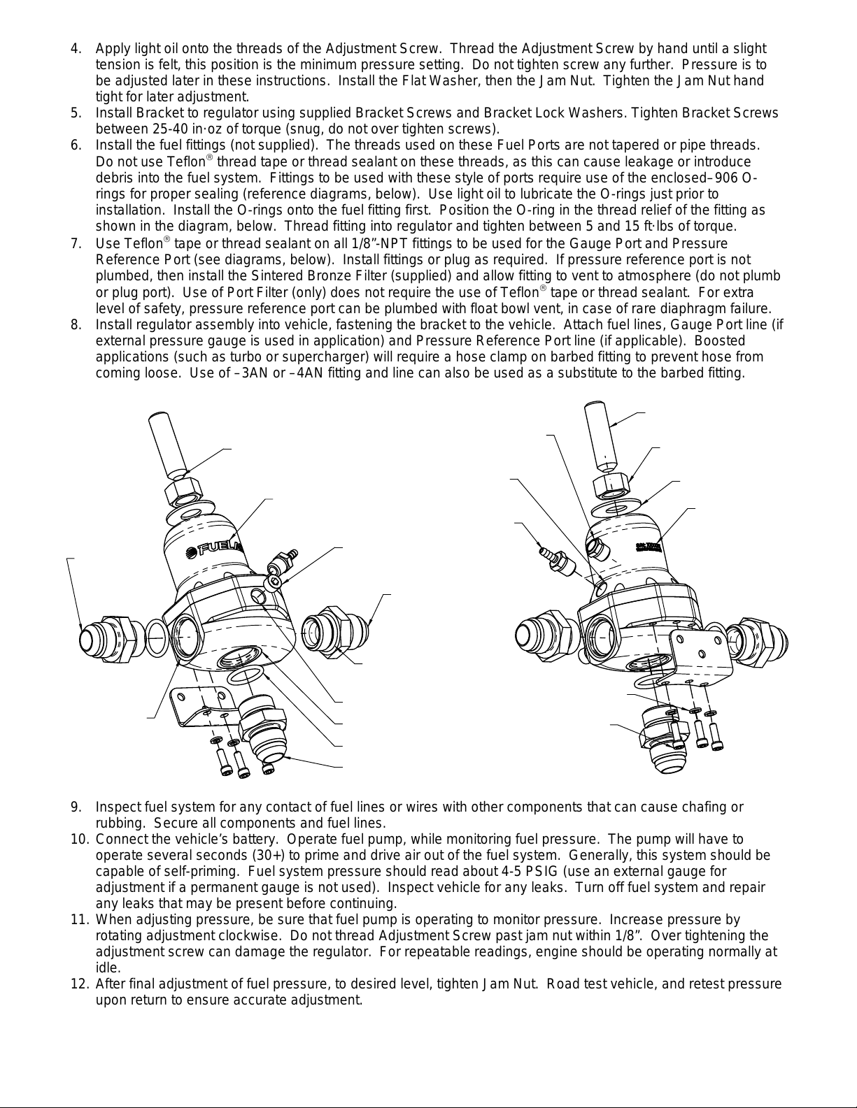
Example -10AN
Port Style Union
Fitting Shown
(Not Supplied)
Install with Cup
toward Regulator
Front
(Logo)
(1/8") Sintered Bronze Filter
(For Naturally Aspireted)
1/8"-NPT Pressure
Reference Port
(Use Fitting or Filter)
(1/8") Barbed Fitting (can be
substituted with other fitting,
for blow-through applications)
Gauge Port Plug
(can be substituted
for gauge or fitting)
Example -10AN
Port Style Union
Fitting Shown
(Not Supplied)
Adjustment Screw
Jam Nut
flat Washer
Unique Serial
Number
Identification
-10AN Inlet or Outlet
Port, Both Sides.
Pressure is
Regulated at
Both Ports.
-910 O-ring Shown,
prior to Fitting
Installation
1/8"-NPT Gauge Port
-10AN Return Line Port
-910 O-ring
Example -10AN Port Style Union
Fitting Shown (Not Supplied)
(3X) Bracket Lock Washer
(3X) Bracket Screw
9. Inspect fuel system for any contact of fuel lines or wires with other components that can cause chafing or
rubbing. Secure all components and fuel lines.
10. Connect the vehicle’s battery. Operate fuel pump, while monitoring fuel pressure. The pump will have to
operate several seconds (30+) to prime and drive air out of the fuel system. Generally, this system should be
capable of self-priming. Fuel system pressure should read about 4-5 PSIG (use an external gauge for
adjustment if a permanent gauge is not used). Inspect vehicle for any leaks. Turn off fuel system and repair
any leaks that may be present before continuing.
11. When adjusting pressure, be sure that fuel pump is operating to monitor pressure. Increase pressure by
rotating adjustment clockwise. Do not thread Adjustment Screw past jam nut within 1/8”. Over tightening the
adjustment screw can damage the regulator. For repeatable readings, engine should be operating normally at
idle.
12. After final adjustment of fuel pressure, to desired level, tighten Jam Nut. Road test vehicle, and retest pressure
upon return to ensure accurate adjustment.
105020622-1, No Rev Sheet 3 of 4
Page 4

LIMITED WARRANTY
FUELAB, a division of FCP, Inc.
62056, USA
Limited Warranty
1.
Manufacturer warrants that the Products sold hereunder will be free from defects in material and workmanship for a
period of 2 Years from the date of purchase to the original purchaser. If the Products do not conform to this Limited
Warranty during the warranty period (as herein above specified), Buyer shall notify Manufacturer in writing, or by
phone, of the claimed defects and demonstrate to Manufacturer satisfaction that said defects are covered by this
Limited Warranty. If the defects are properly reported to Manufacturer within the warranty period, and the defects
are of such type and nature as to be covered by this warranty, Manufacturer shall, at its own expense, furnish
replacement Products or, at Manufacturer's option, replacement parts for the defective Products. Removal of
Products from vehicle (
combustion engine. This product is
shipping to Manufacturer and installation of the replacement Products or replacement parts shall be at Buyer's
expense.
Other Limits
2.
THE FOREGOING IS IN LIEU OF ALL OTHER WARRANTIES, EXPRESS OR IMPLIED, INCLUDING BUT NOT
LIMITED TO THE IMPLIED WARRANTIES OF MERCHANTABILITY AND FITNESS FOR A PARTICULAR
PURPOSE. Manufacturer does not warrant against damages or defects arising out of improper or abnormal use or
handling of the Products; against defects or damages arising from improper installation (where installation is by
persons other than Manufacturer), against defects in products or components not manufactured by Manufacturer,
or against damages resulting from such non-Manufacturer made products or components. Manufacturer passes on
to Buyer the warranty it received (if any) from the maker thereof of such non-Manufacturer made products or
components. This warranty also does not apply to Products upon which repairs have been effected or attempted
by persons other than pursuant to written authorization by Manufacturer.
("Manufacturer") warrants its
.
Vehicle means any automotive, bike or marine transportation powered by an internal
.
, having its principal place of business at
FUELAB
intended or designed for use on aircraft, experimental or otherwise.),
NOT
products (the "Products") as follows:
826A Morton Court, Litchfield, IL
Exclusive Obligation
3.
THIS WARRANTY IS EXCLUSIVE. The sole and exclusive obligation of Manufacturer shall be to repair or replace
the defective Products in the manner and for the period provided above. Manufacturer shall not have any other
obligation with respect to the Products or any part thereof, whether based on contract, tort, strict liability or
otherwise. Under no circumstances, whether based on this Limited Warranty or otherwise, shall Manufacturer be
liable for incidental, special, or consequential damages.
Other Statements
4.
Manufacturer's employees, representatives' and/or resellers ORAL OR OTHER WRITTEN STATEMENTS DO NOT
CONSTITUTE WARRANTIES, shall not be relied upon by Buyer, and are not a part of the contract for sale or this
limited warrant y.
Entire Obligation
5.
This Limited Warranty states the entire obligation of Manufacturer with respect to the Products. If any part of this
Limited Warranty is determined to be void or illegal, the remainder shall remain in full force and effect.
Warranty Service
6.
What Does This Warranty Not Cover?
flood) is not covered. Also, consequential and incidental damages are not recoverable under this warranty. Some
states do not allow the exclusion or limitation of incidental or consequential damages, so the above limitation or
exclusion may not apply to you.
How Do You Get Service?
Registration card, or register on-line at www.fuelab.com/warranty within 30 days of purchasing the Product.
If something goes wrong with your product contact FUELAB at 1-800-541-2345, International customers call 001-
217-324-3737, for a Return Authorization Number (RMA). After receiving your RMA send it postage paid, fully
insured, with a brief written description of the problem to:
.
.
.
Any problem that is caused by abuse, misuse, or an act of God (such as a
In order to be eligible for service under this warranty you
MUST
return the Warranty
FUELAB Warranty Department, 826A Morton Court, Litchfield, IL 62056
We will inspect your Product and contact you within 72 hours of receipt to give the results of our inspection and an
estimate of the labor and/or parts charges required to fix the Product, if applicable. If covered under this limited
warranty Manufacturer will repair Product and return it to you at no cost. If the Product is NOT covered under this
warranty and if you authorize repairs, we will return the repaired Product to you COD, or prepaid via credit card,
within 72 hours. There is no charge for inspection. If return product is found to be free of defects a $25.00 shipping
and handling charge will be applied. We will return the repaired Product to you COD, or prepaid via credit card,
within 72 hours.
105020622-1, No Rev Sheet 4 of 4
 Loading...