

Page 1
OPERATING INSTRUCTIONS
RESPIRATOR A B V - A/ - U
/
MANUELL
RESPIRATOR
MANUAL
max.
EXPIRATION (mbar)
max.min.
mbar
INSPIRATION (mbar)
ATEMZEITVERHÄLTNIS
INSP.: EXSP.
1:4
2:1
1:3
1,5:1
1:2
1:1
1:1,5
606
7
50
8
40
9
30
10
25
12
20
14
16
min.
MAX.DRUCK
mbar
60
10
55
15
20
50
45
25
303540
MIN.DRUCK
mbar
25
20 10
15
SENSITIVITÄT
P mbar
5
ARTEC
ABV - U
2
Status: 12 / 2006
06/98-07hö
F. STEPHAN GmbH · Medizintechnik · D-56412 Gackenbach · Kirchstr. 19 · Tel. (06439) 9125-0 · Fax (06439) 9125-111 · [email protected] · www.stephan-gmbh.com
Page 2

OPERATING INSTRUCTIONS Respirator ABV-A / U
Table of Contents
1. Attention.................................................................................................................. 3
Manufacturer:.............................................................................................................. 4
2. Design and description of functions....................................................................... 5
2.1 Overview............................................................................................................ 5
2.2 Technical function during the „inspiratory phase“. ............................................. 6
2.3 Technical function during the „expiratory phase“ ............................................... 7
2.4 Technical function during „manual respiration“ .................................................. 8
2.5 Respirator with patient component..................................................................... 9
2.6 Adjusting respirator parameters....................................................................... 10
3. MODIFICATIONS AND OPTIONS........................................................................ 15
4. OPERATION CHECK...........................................................................................
4.1 Leakage test of complete system ....................................................................
16
16
4.2 PEEP (postive end expiratory pressure).......................................................... 18
4.3 PLATEAU (upper pressure limit)...................................................................... 19
4.4 Respirator function........................................................................................... 19
4.5 Pressure monitor ............................................................................................. 20
5. Cleaning the respirator.......................................................................................... 21
5.1 Patient component........................................................................................... 21
5.1.1 Disassembly............................................................................................... 21
5.1.2 Cleaning..................................................................................................... 21
5.1.3 Sterilisation ................................................................................................
5.1.4 Re-assembly..............................................................................................
22
22
5.1.5 Front panel and housing of the respirator.................................................. 22
6. Calibration.............................................................................................................
7. Troubleshooting Guide..........................................................................................
23
24
8. SPECIFICATIONS................................................................................................ 26
8.1 Respirator module............................................................................................ 26
8.2 Patient component.......................................................................................... 27
8.3 Pressure monitor .............................................................................................
9. Maintenance and Servicing...................................................................................
28
29
2
Page 3

OPERATING INSTRUCTIONS Respirator ABV-A / U
1. Attention
This product is in compliance with all current directives and statutory regulations
The design and construction of this device comply with the following regulations and norms:
DIN EN 60601-1 (and following) Medical electrical equipment
DIN 13 252 Inhalation Anaesthesia Devices
DIN VDE 0750-211 Medical electrical equipment, partial Requirements
for safety of anaesthesia machines
VBG 62/04.69 Oxygen
VBG 62/03.70 Implementing Ordinance for UW Oxygen
In compliance with the law governing technical operational devices ( Instrument Safety Act)
of June 24 1968 (German Civil Code Gazette/BGBI, page 717) in the wording of Amending
Act of August 13 1979 (BGBI, page 1432) in the law governing Safety of Medical Devices
(MedGV) of January 14 1985 (BGBI 2. page 93) we point out that:
1. The operation of this device is to be carried out by duly trained personnel only. Exact
knowledge and understanding of the operating instructions are necessary.
2. The device may only be used for the purposes indicated in the operating instructions.
3. The device must be serviced at regular intervals by trained personnel. Such
servicing must be recorded in the device logbook provided.
4. The manufacturer stipulates servicing and maintenance every six months by an
authorised service technician. For this reason, a maintenance agreement must be
concluded.
5. Devices equipped with pressure relief systems should, for safety reasons, undergo a
general reconditioning at least every five years.
6. For medico-technical devices with electrical connections, strict compliance with VDE
directives and IEC 601 (VDE 0751) is necessary. Accordingly, these devices may
only be serviced by the manufacturer or his expressed authorised representative.
7. An emergency respirator (e.g., ambu bag) must be kept near the device.
8. Operating conditions:
Power supply: 230 V mains voltage
Room temperature: between 10°C and 40°C
relative humidity 90%
3
Page 4

OPERATING INSTRUCTIONS Respirator ABV-A / U
Do not place any large heat source around or on the device. Make sure there is
sufficient space around the device for ample heat dissipation.
9. Check all functions carefully to see that they are working properly according to the
checklist and operating instructions.
10. Under the above conditions the device can be used in „continuous operation“
mode.
11. Functioning of this device can be negatively influenced by other devices being
used in close proximity: such as short-wave surgery and diathermy devices,
defibrillators, radiothermy, etc.
The manufacturer is not liable for any damage to the machine caused by improperly
operating the machine or non-compliance with the instructions mentioned above.
Manufacturer:
F. Stephan GmbH
Kirchstraße 19
D-56412 Gackenbach.
Tel.: (+49) 6439-9125-0
Fax: (+49) 6439-9125-111
e-mail: [email protected]
Homepage: http://www.stephan-gmbh.com
4
Page 5
OPERATING INSTRUCTIONS Respirator ABV-A / U
2. Design and description of functions
2.1 Overview
The respirator module consists of a pneumatic and an electronic control component
(respirator ABV-A / U and patient component), as well as an electronic pressure monitor and,
as an option, monitors for oxygen concentration, anaesthetic gases and ventilation
parameters.
The electronics of the respirator module are supplied with mains power (230 V / 50 Hz), while
the pneumatic requires propellant in the form of compressed air (3 - 5 bar)
The respirator is suitable for controlled anaesthesia in a semiclosed system for children and
adults.
The patient component can easily be disconnected and replaced by means of snap couplings
for purposes of hygiene (partly autoclaveable up to 134°C).
General Description
Compressed air with a line pressure of 3-5 bar must be used to supply the respirator ABV-A
with a propellant. The various respiration parameters can then be set on the respirator.
RESPIRATOR
EIN / AU S
max.
EXPIRATION(mbar)
VOLUMEN
Beatmungsdruck
INSPIRATION(mbar)
max.
min.
mbar
ccm
1500
1400
1300
1200
1100
1000
900
800
700
600
500
400
300
200
100
0
3
MANUAL
MANUELL
RESPIRATOR
4 5
2
ATEMZEITVERH LTNIS
INSP.: EXSP.
1:4
2:1
1:3
1
,5:1
1:2
1:1
1:1,5
606
7
50
8
40
9
30
10
25
12
20
14
16
1
min.
MAX.DRUCK
mbar
10
60
CMV
55
15
20
50
IPPV
45
25
303540
MIN.DRUCK
mbar
525
2min
20
10
ASSIST.
15
KONTR.
SENSITIVITÄT
Pmbar
-2
-0,2
ARTEC
ABV - U
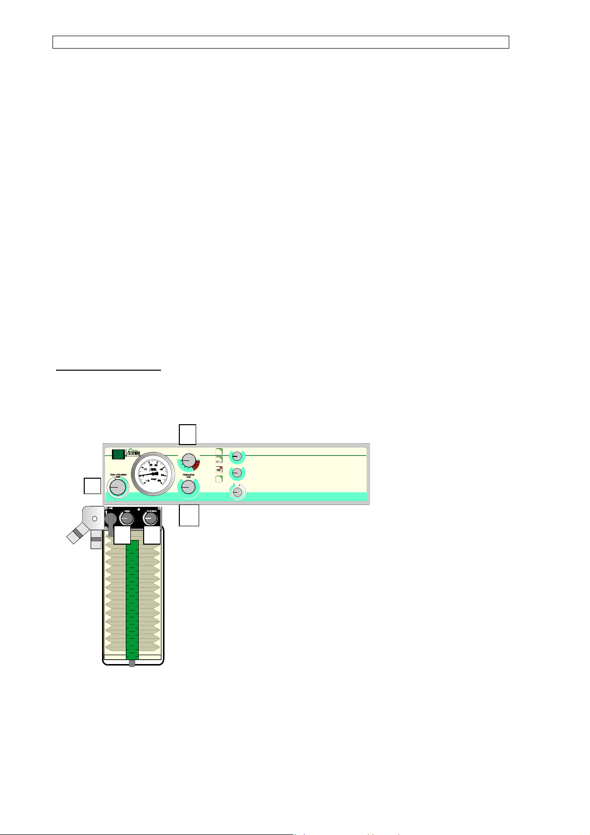
1) Frequency
2) Respiratory time quotient
3) Volume
4) PEEP
5) Plateau
A sufficient flow of fresh gas must be ensured. Observation of the respiration schemes of the
anaesthetic device „ARTEC“ is analysed in two parts.
5
Page 6
OPERATING INSTRUCTIONS Respirator ABV-A / U
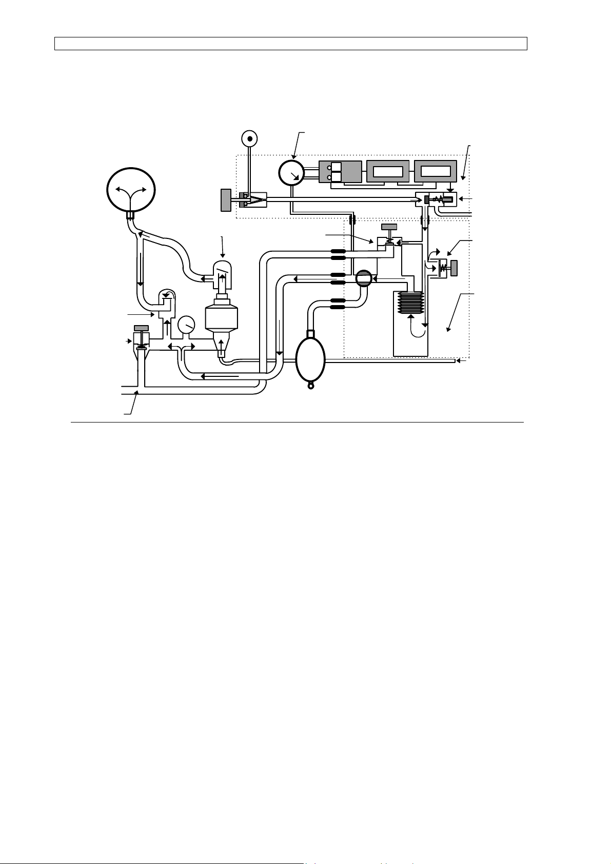
2.2 Technical function during the „inspiratory phase“.
Expirationvalve
Gas exceedingvalve ( Berner )
Excess Gas
Functionsscheme
Inspiration
Volume-
valve
Inspiration-
valve
AIR
3 - 5 Bar
PEEP - Valve
0 - 12 mbar
Manometer
Respirator
P
P
CPU
Powersupply
Freschgas
solenoidvlave
PLATEAU Valve
15 - 60 mbar
Pat.compnt.
To begin inspiration, the solenoid valve of the respirator opens. Via the ZGA connection,
compressed air (so-called „propellant") flows into the patient component. The amount of inflowing gas is adjusted at the volume valve. Opening time of the solenoid valve is regulated
by respiratory frequency and time quotient.
The build-up of pressure in the Plexiglas cylinder (bottle) compresses the bellows bag. The
gaseous mixture consisting of fresh gas and returned patient gas present in the bellows bag
closes the expiration valve and is led to the CO
absorber. The gas opens the inspiration
2
valve and flows to the patient. Respiration pressure can be read both on the pressure gauge
of the respirator and on the circuit system. When the respiration pressure reaches the pre-set
plateau pressure limit before the end of the inspiration time, the PLATEAU valve opens,
releasing propulsion gas into the open. The integrated pressure monitor allows continuous
monitoring of pressures during the inspiration phase. A visual and acoustic signal warns
when the pre-set upper pressure limit has been exceeded.
6
Page 7
OPERATING INSTRUCTIONS Respirator ABV-A / U
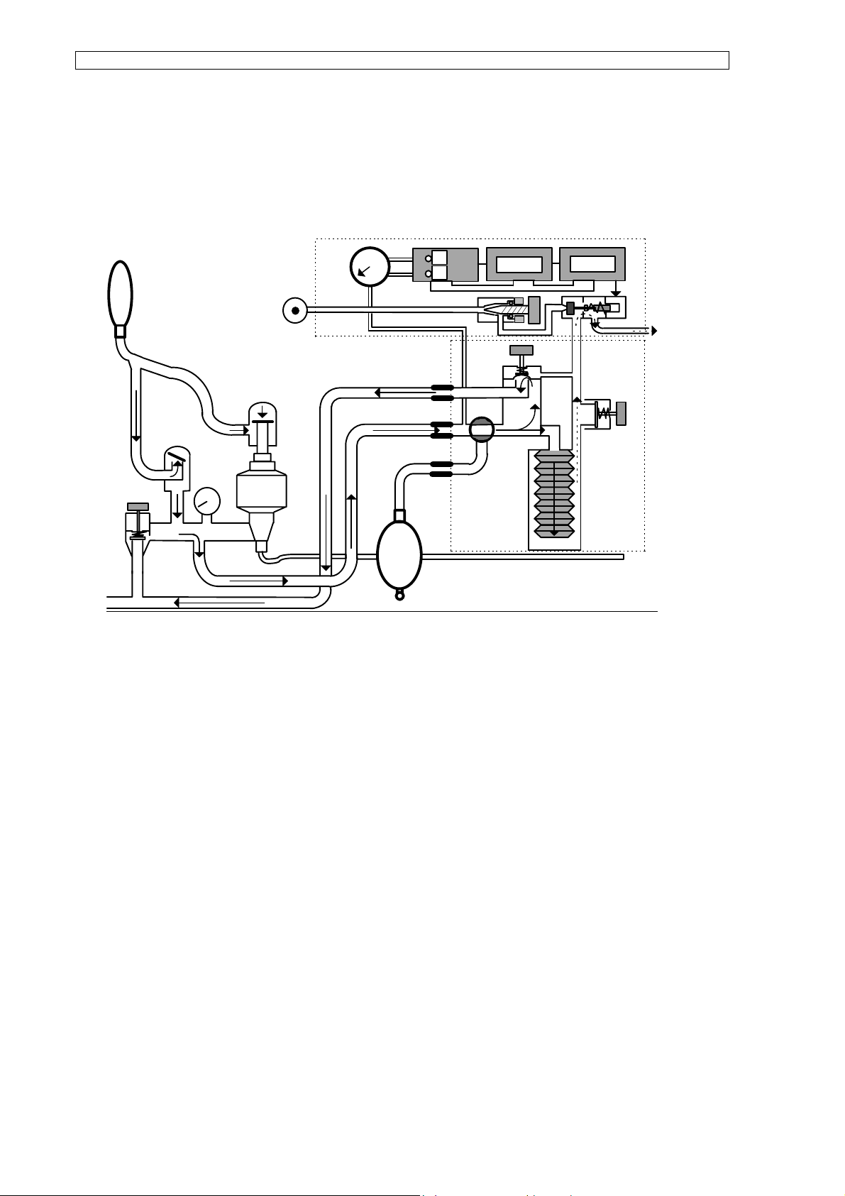
2.3 Technical function during the „expiratory phase“
Functional scheme expiration
Functionsscheme
Expiration
P
Powersupply
Following the
inspiratory
phase, the
solenoid valve
shuts off the
flow of
propulsion gas.
Pressure in the
lungs of the
patient closes
the inspiration
valve and
opens the
expiration valve. The patient exhales into the respiration bellows which is then pressed down.
At the same time, fresh gas flows into the bellows. The propellant gas being pressed out of
the glas cylinder is released into the open via the solenoid valve. The excessive exhaled air is
fed via the PEEP valve diaphragm. The PEEP diaphragm retains as much pressure in the
system as had been pre-set on the patient component adjustable PEEP value.
The reduction in respiratory pressure and the remaining positive end expiratory pressure
(PEEP) are displayed on the pressure gauges of the circuit system and the respirator.
7
Page 8
OPERATING INSTRUCTIONS Respirator ABV-A / U
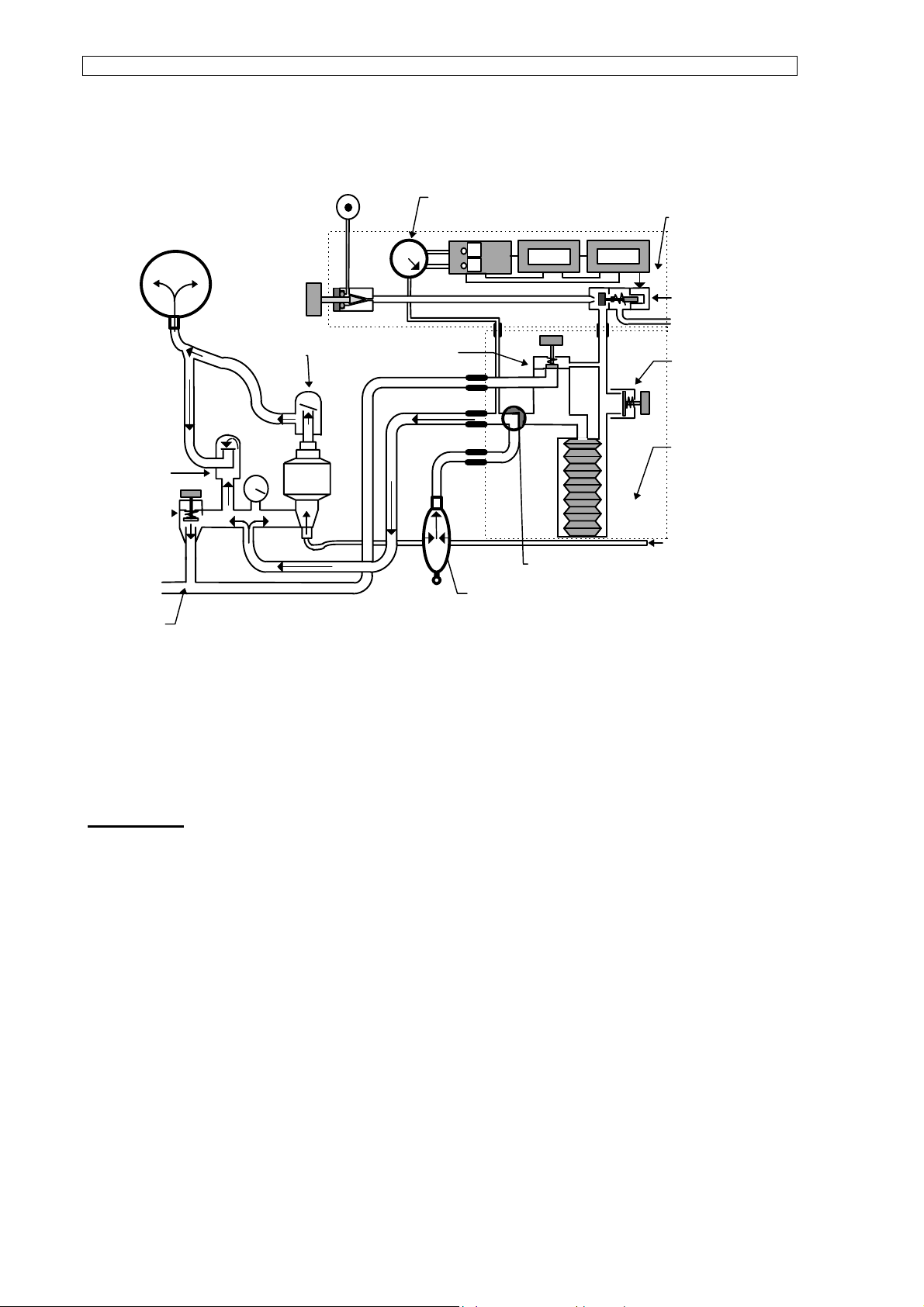
2.4 Technical function during „manual respiration“
Manometer
Functionsscheme
Manual Ventilation
AIR 3-5
Bar
Respirator
Expirationsvalve
Excess pressure
valve (Berner)
Exceeding Gas
Volume-
valve
Inspiration-
valve
PEEP - Valve
0 - 12 mbar
Bag
Switch over lever
in „manual“ position
Freschgas
Solenoid valve
PLATEAU Valve
15 - 60 mbar
Patient
component
By means of the switch over lever „Manual / Respirator“ on the patient component, the
manual respiration bag is connected directly to the circuit system. Pressure build-up now
develops directly via the manual respiration bag.
CAUTION !
Pressure limitation is effected only via the excess valve (Berner valve) of the circuit system !
The PLATEAU valve of the patient component is disabled.
Make sure the Berner valve is open after switching over to „Manual“.
The PEEP and PLATEAU functions of the patient component are disabled. The residual
pressure remaining in the circuit system can be pre-set in a range of 0 - 50 mbar via the
Berner valve.
Make sure that an additional connection of the scavenging system (NGA) is made to the
Berner valve.
8
Page 9
OPERATING INSTRUCTIONS Respirator ABV-A / U
2.5 Respirator with patient component
The ABV-A / U respirator has been designed for controlled anaesthesia respiration in
compliance with state-of-the-art technology.
Operation of the respirator is driven by compressed air, timed and volume constant; the
maximum inspiration pressure can be pre-set at the patient component
The patient component is based on the „bag-in-bottle principle“ with which a separation of
respiratory gas from control gas is achieved. In addition, the patient component serves as a
reservoir.
2
MANUELL
1
RESPIRATOR
EIN / AU S
Beatmungsdruck
MANUAL
EXPIRATION(mbar)
max.
6 7
VOLUMEN
INSPIRATION(mbar)
max.
min.
mbar
ccm
1500
1400
1300
1200
1100
1000
900
800
700
600
500
400
300
200
100
0
RESPIRATOR
5
3
ATEMZEITVERH LTNIS
INSP.: EXSP.
1:4
2:1
1:3
1
,5:1
1:2
1:1
1:1,5
606
7
50
8
40
9
30
10
25
12
20
14
16
4
min.
MAX.DRUCK
mbar
10
60
CMV
55
15
20
50
IPPV
45
25
303540
MIN.DRUCK
mbar
525
2min
20
10
ASSIST.
15
KONTR.
SENSITIVITÄT
Pmbar
-2
-0,2
ARTEC
ABV - U
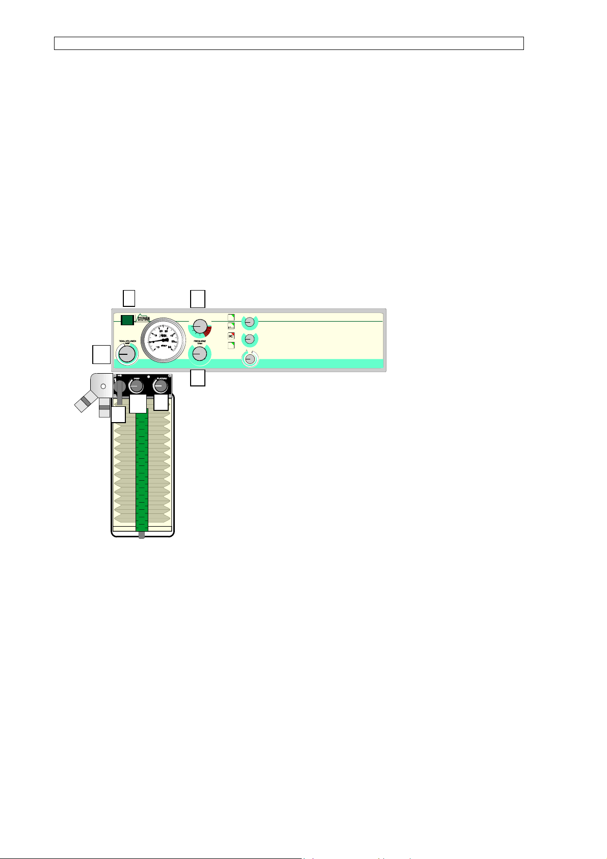
The ON/OFF switch (1) is
situated at the upper left of the
front control panel.
Immediately below is the
volume regulation valve (2)
with which the volume flow to
the patient’s lungs during the
inspiratory phase can be
regulated. The frequency of
the respiratory cycle can be
varied between 6 and 60
inspirations per minute by means of the potentiometer „Frequency“ (3). The ratio between
inspiratory phases and expiratory phases of 1:4 to 2:1 can be pre-set using the range switch
„Respiratory time quotient“ (4).
A pressure-proof respiratory pressure gauge shows the circuit system pressure in the range
of -10 to 60 mbar.
In the event of power failure, an acoustic signal is activated for at least 60 seconds. By using
the switch-over lever (5) found on the patient component, either the respirator or manual
respiration can be activated.
The PEEP valve (6) regulates the end expiratory pressure up to a maximum of 12 mbar. The
PLATEAU valve (7) achieves a constant upper limit respiratory pressure of maximum 60
mbar.
9
Page 10
OPERATING INSTRUCTIONS Respirator ABV-A / U
2.6 Adjusting respirator parameters
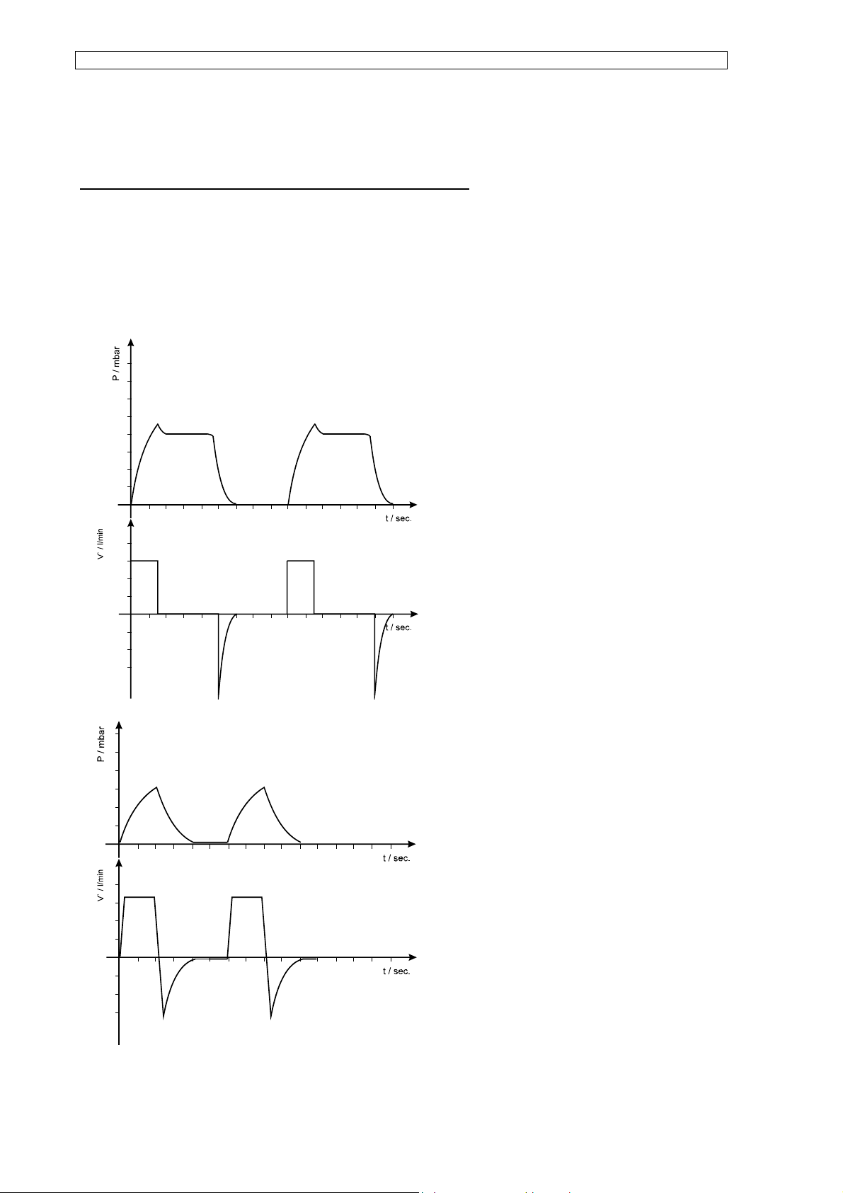
Inspiration flow changes on volume regulating valve
Principally, it is possible to vary the inspiration flow, using the volume regulating valve, to
achieve a tidal volume of 0-1500 ml. Together, however, with the PLATEAU pressure distinct
respiratory curves can be generated.
For greater inspiratory flow, the maximum
pressure, here limited by the PLATEAU valve,
is quickly reached. Thereafter, the pressure
does not change until at the end of the
inspiratory phase. This PLATEAU serves to
improve the alveolar exchange of gas. Volume
flow to the patient falls, after initially reaching
the PLATEAU pressure, back to „0“until it slips
to negative values through the introduction of
expiration. Because as much gas must flow
back from the patient in the expiratory phase
as had been led to him in the inspiratory
phase, the unit area of the inspiratory flow
curve must be equal to that of the expiratory
flow curve.
The inspiration flow can be reduced so far that
the PLATEAU pressure is reached exactly at
the end of the inspiratory phase. In the case of
renewed reduction in inspiratory flow, a
respiratory curve can be realised, in which the
maximum pressure reached lies below that of
the PLATEAU pressure.
10
Page 11
Frequency adjustment
OPERATING INSTRUCTIONS Respirator ABV-A / U
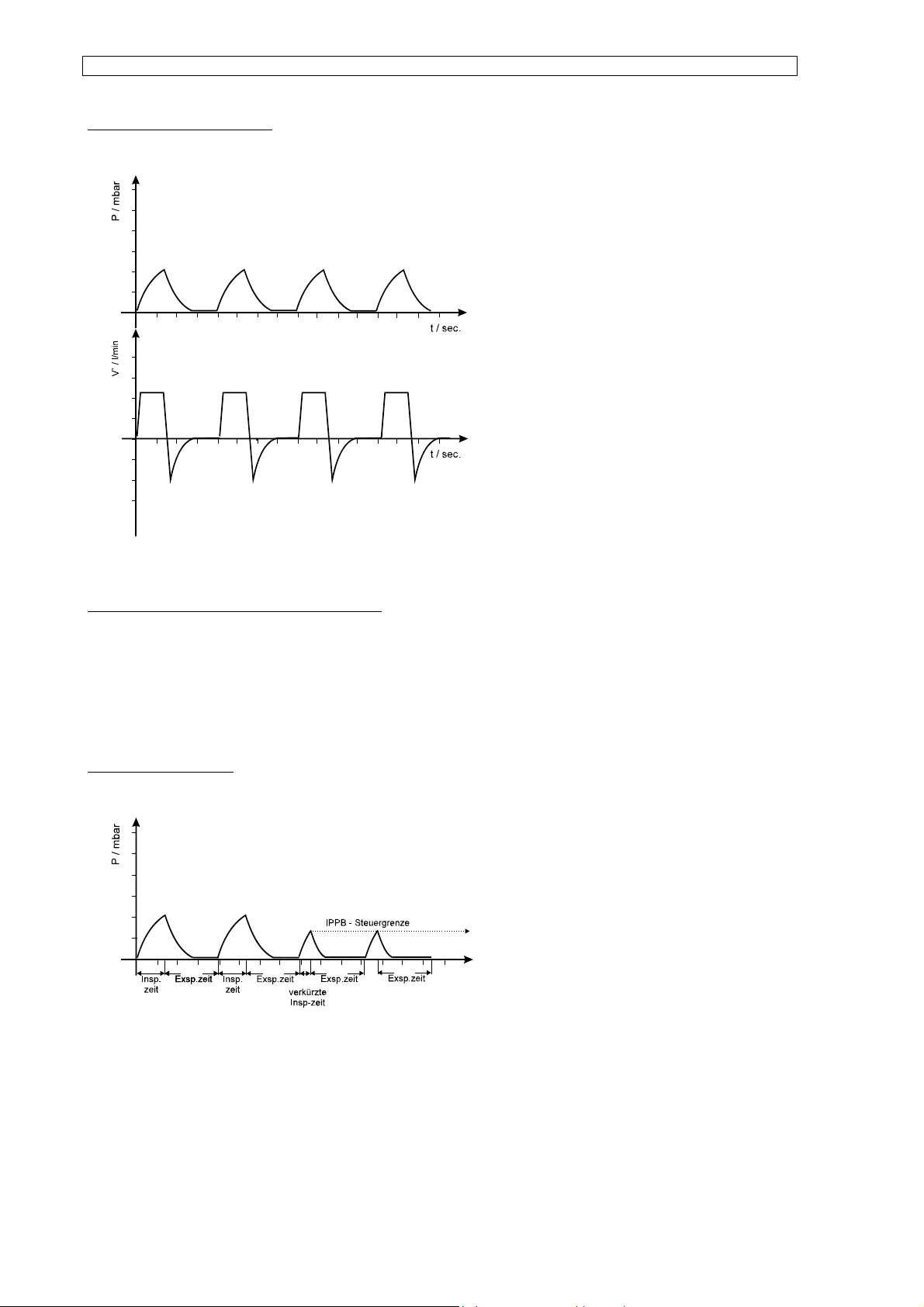
The frequency, i.e., the number of
inspirations per minute can be infinitely
adjusted from 6 to 60 per minute. It must be
remembered, however, that in the case of
increased frequency the respiratory minute
volume does in fact remain constant, but the
tidal volume sinks. Very high frequencies can
result in the maximum pressure desired not
being reached and this, in turn, leads to
respiration that is too flat. To prevent this
occurrence, increase the inflow volume at the
volume control stem.
Respiratory time quotient (insp:exp)
The respiratory time quotient, i.e., the ratio of inspiration time to expiration time, can be
randomly varied from 1:4 to 2:1, whereby the respiratory frequency is not influenced.
Control limit IPPB
This respirator model allows you to carry out
pressure-controlled respiration (IPPB), where
the expiratory phase is introduced upon
reaching the pre-set maximum pressure. The
pressure limit alarm of the integrated
pressure monitor is used as a pressure
control.
The new inspiratory phase is then triggered by the pre-adjusted frequency time.
11
Page 12
OPERATING INSTRUCTIONS Respirator ABV-A / U
Sensitivity adjustment (optional, only for ABV-U respirators)
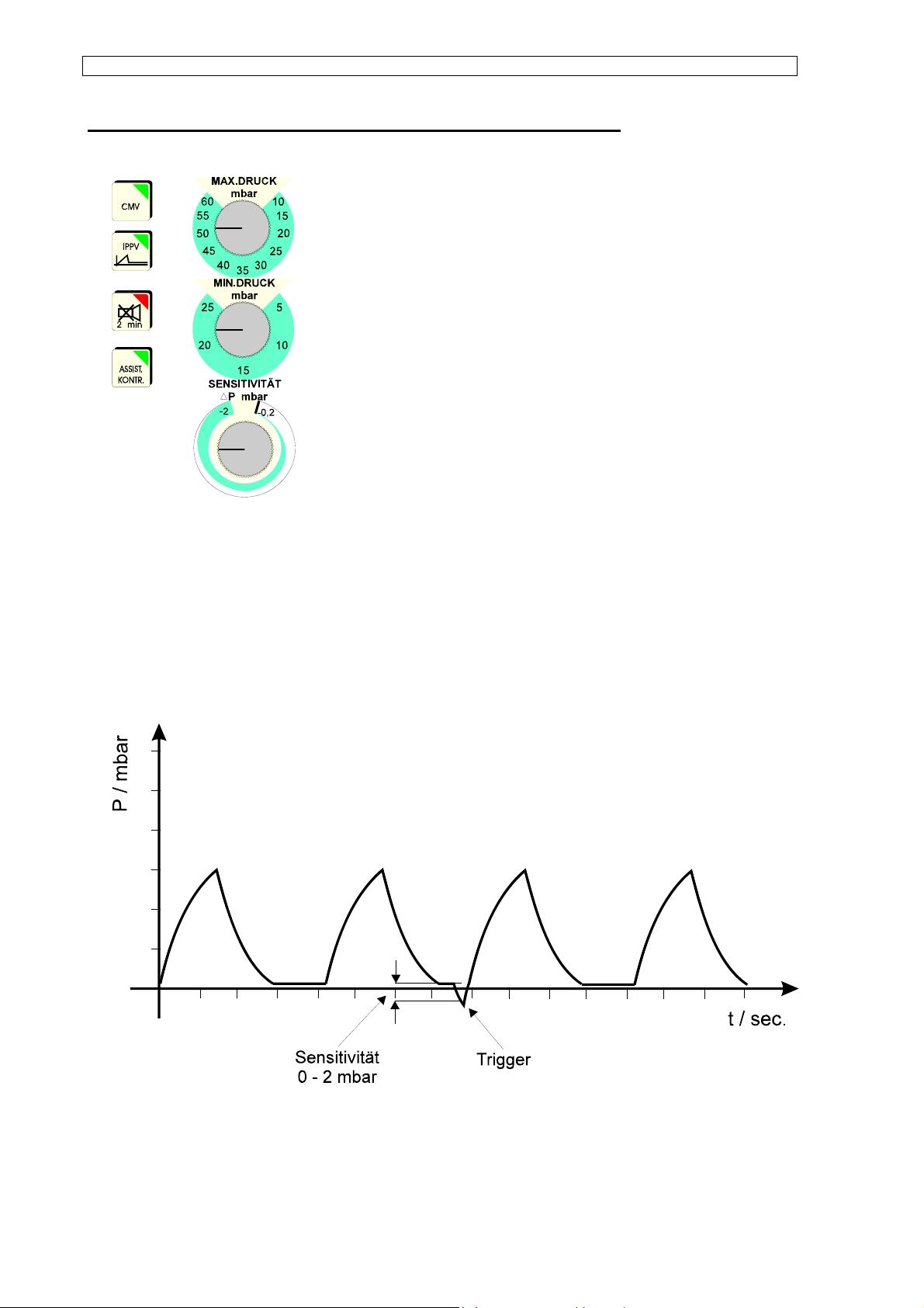
In order to work more effectively in the case of not completely
disabled breathing or reoccurring spontaneous breathing of the
patient, we provide a respirator module „ABV-U“ with an additional
function for assisted-controlled respiration.
Through the inhalation efforts of the patient, a vacuum develops in
the system which induces the respirator to carry out an additional
completely controlled tidal volume according to the pre-set
respiration parameters. If the patient’s spontaneous breathing
comes to a complete standstill, respiratory frequency is reduced to
the pre-set values and controlled respiration continues
automatically.
The suction produced by the patient that is necessary to trigger this function can be set at a
sensitivity of 0.2 to 2 mbar pressure difference using the sensitivity adjustment knob.
Should possible end expiratory pressure be used, the trigger threshold automatically uses
this value.
12
Page 13
OPERATING INSTRUCTIONS Respirator ABV-A / U
PEEP adjustment
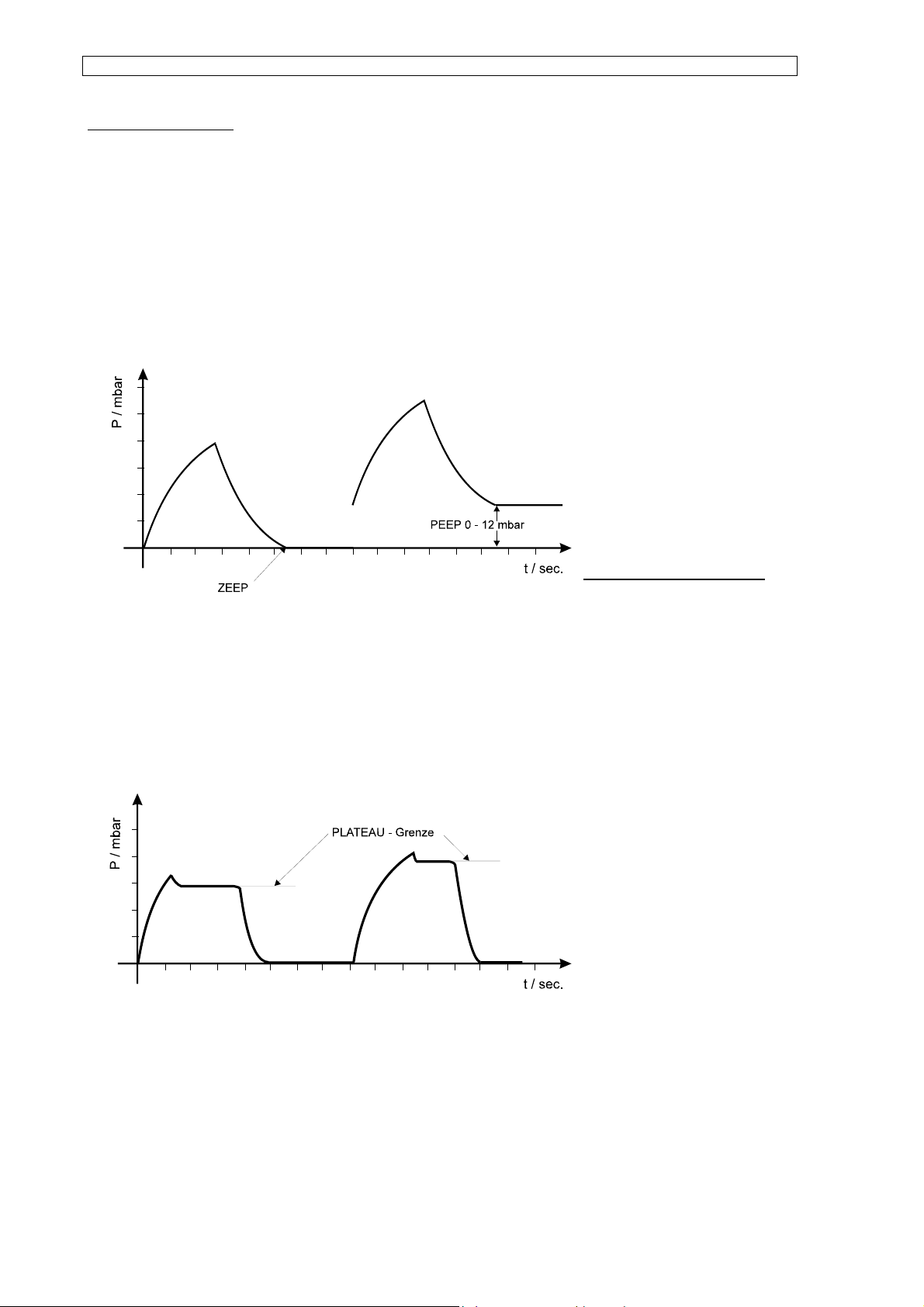
The so-called „positive end expiratory pressure“ is adjusted with the left control knob of the
patient component. The purpose of increasing the pressure curve in the expiratory phase is
to deny the alveoli the possibility of collapsing or even to re-expand already collapsed alveoli
so that they can participate in exchange of gas once again. This PEEP can be infinitely
adjusted from 0 to 12 mbar; however, a certain dependence on flow of fresh gas exist which
must be considered when adjusting.
The first curve runs with the
PEEP value zero or called ZEEP
(zero end expiratory pressure),
whereas the second curve
depicts true PEEP.
PLATEAU adjustment
The maximum inspiratory
pressure is set using the right control knob at the patient component. The purpose of the socalled PLATEAU is to retain the inhaled gas at a constant pressure in the lungs for a short
time, in order to improve the alveolar exchange of gas. In addition, the PLATEAU can be
used as an upper pressure limit or security against excessive build-up of pressure. The
PLATEAU value can be varied from 10 to 60 mbar.
The first curve shows a low
PLATEAU value, at which a
considerable piece of the
respiratory pressure curve is cut
off.
The second curve requires
higher pre-set value of the
PLATEAU, but it is visible that pressure limit has no influence on the duration of
inspiration.This PLATEAU is, however, to be seen only as pressure limitation, and is in no
way to function as a pressure- controlled respirator.
13
Page 14
OPERATING INSTRUCTIONS Respirator ABV-A / U
Pressure monitor
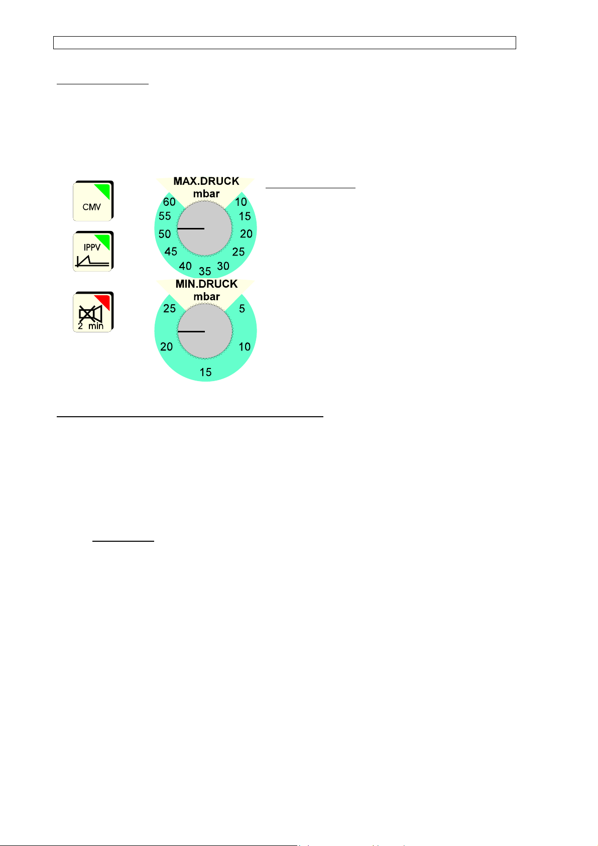
The pressure monitor is an electronic module, divided into two pressure measuring ranges
for continuous monitoring of patient pressure.
1. Max. pressure
The max. pressure monitor is equipped with a
potentiometer, with which the maximum respiratory
pressure can be infinitely adjusted from 6 to 60 mbar.
Should the patient pressure exceed the pre-set max.
pressure, the pressure monitor sets off an optic and
acoustic warning for the duration the limit is
exceeded.
2. Minimum pressure or disconnection component
The minimum pressure range can be infinitely adjusted from 5 to 25 mbar using the
potentiometer. During the respiratory phase, the minimum pressure must exceed and fall
below this pre-set limit, otherwise an optic and acoustic alarm is triggered.
blinking red
: constant exceeding of the minimum limit (PEEP too high) or
constantly falling below the minimum limit value. (disconnection).
Should a disconnection exist in the respiration system that leads to a steep drop in pressure,
a disconnection alarm is triggered with a 15 second delay.
By pressing the membrane key „Stand-by“ of the pressure monitor, the acoustic alarm can be
suppressed for the duration of 2 minutes.
The pressure monitor is activated via the ON switch of the respirator.
It is only in operation while the respirator is switched on.
14
Page 15
OPERATING INSTRUCTIONS Respirator ABV-A / U
3. MODIFICATIONS AND OPTIONS
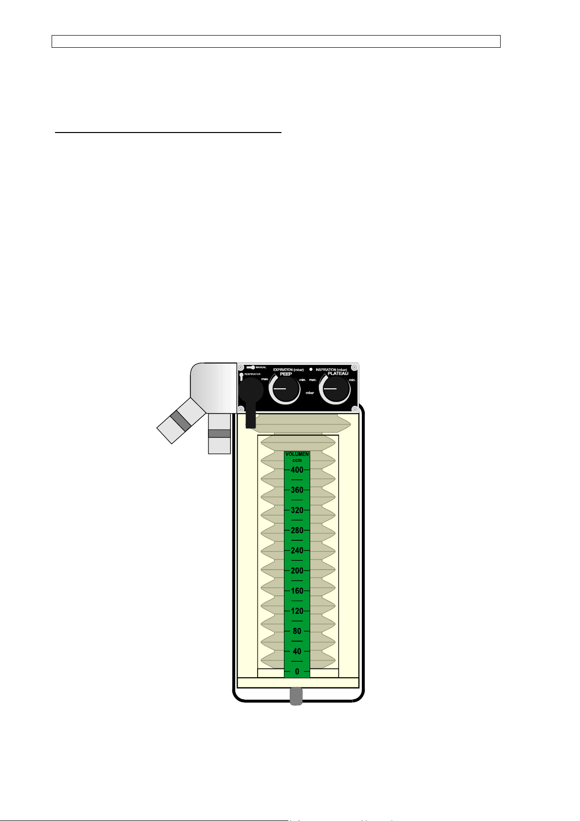
Patient component for paediatric respiration
To enable the user to easily and quickly use the respirator for paediatric purposes without
the need of tedious refitting, a special plexi-bottle with inner chamber has been designed.
A rubber bellows designed for paediatric respiration is inserted in the inner chamber. The
plexi-bottle can be fitted in place in no time. The volume of the paediatric system is variable
from 0 to 400 ml.
Furthermore, it is recommended to adjust the circuit system of the respirator to the special
conditions of paediatric anaesthetisation through the use of a volume reducing children’s
hose system (Ulmer set) and removing one CO2 absorber.
15
Page 16
OPERATING INSTRUCTIONS Respirator ABV-A / U
A
4. OPERATION CHECK
4.1 Leakage test of complete system
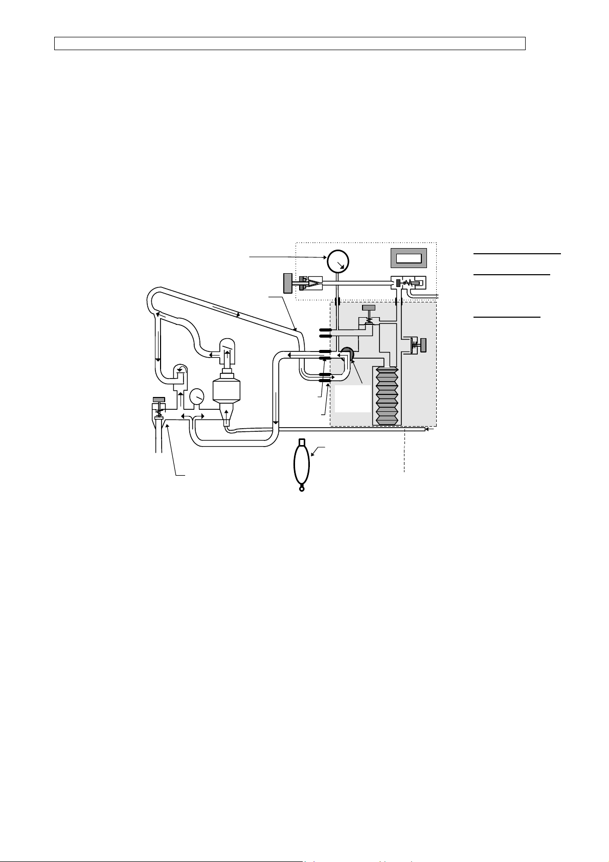
The leakage test of the respirator is carried out in conjunction with that of the circuit system.
In this way leakage is checked for the entire system.
Respiration
pres.gauge
ttach manual
hose onto ypiece
Berner - Valve tof
„CL“
RESPIRATOR
MANUAL
Switch to
„MANUAL“
remove manua l resp.
Bag from hose
Patient
component
CPU
Freschgas
Leakage test of
entire system:
Basic setup:
• close flow
regulator
valve on gas
mixing unit
• adjust
pressure
regulator
valve to CL
• remove mask
from Y-piece
(1)
• separate manual respiration bag from corrugated hose
• attach corrugated hose (3) to Y-piece to form closed system between circuit system and
respirator
• adjust switch lever on the patient component from „respirator“ to „manual“
16
Page 17

OPERATING INSTRUCTIONS Respirator ABV-A / U
Test procedures:
• After having checked that the respiratory pressure gauge is set at zero (2) carefully open
the oxygen flow regulator valve until the pressure gauge remains constant at 60 mbar.
• The amount of gas leagkage can be read on the respective measuring tube
• Should leakage be below 250 ml/min, the circuit system is sufficiently sealed for operation.
• Should leakage exceed 250 ml/min, the following points are to be checked:
⇒ tightness of connection union
⇒ tightness of threaded couplings
⇒ gaskets and o-rings
⇒ damage to corrugated hose
⇒ damage to o-rings of the patient component connection (firmly mounted under the
repirator)
Should unacceptable leakage still exist after a second test, notify technical support.
17
Page 18

OPERATING INSTRUCTIONS Respirator ABV-A / U
4.2 PEEP (postive end expiratory pressure)
Basic setup:
− circuit system in operation mode
− on circuit system switch excess valve to CL (closed) position
− remove mask from Y-piece
− calibrate respiratory pressure gauge on respirator
− connect Y-piece to test lunge
− switch lever on patient component to respirator
Test Procedure:
− adjustment of oxygen or compressed air flow of 5 l/min
− adjust PEEP valve to „max.“. PEEP value at respiratory pressure gauge must rise to 12 +/-
2 mbar within a few seconds.
− adjust PEEP valve to „min.“. PEEP value at respiratory pressure gauge must fall again to 0
mbar
− tolerance +/-1 mbar
− notify technical support if deviations from these values are observed.
18
Page 19

OPERATING INSTRUCTIONS Respirator ABV-A / U
4.3 PLATEAU (upper pressure limit)
Basic setup:
− circuit system in operation mode
− on circuit system switch excess valve to CL (closed) position
− remove mask from Y-piece
− connect Y-piece to test lunge
− switch lever on patient component to respirator
− calibrate respiratory pressure gauge on respirator
− adjust PEEP valve to „min“
− adjust PLATEAU valve to „max“ and switch respirator on
− open volume valve completely
− adjust respiratory frequency to 10/min
− set respiratory ratio to 2:1
− adjust on gas mixing unit dosage of fresh gas to 5 l/min.
Test Procedure
− In the inspiration phase the respiratory pressure must register 60 mbar at the respiratory
pressure gauge
− Tolerance: +5 mb mbar
− When adjusting down the PLATEAU during the inspiration phase, the pressure is to
continuously drop to approx. 10 mbar (tolerance: +5 mbar)
4.4 Respirator function
− Turn on mains power switch on the respirator module
− Switch on respirator’s operating switch
− The key of the operating switch must illuminate green showing readiness for operation
− If key is not lit green, disconnect the power plug and check fuses, and if necessary
replace.
19
Page 20

OPERATING INSTRUCTIONS Respirator ABV-A / U
Power failure alarm of the respirator
− Turn on operating switch of the respirator
− After one minute switch off the power switch of the respirator module
− An audio warning signal will sound at the same time
4.5 Pressure monitor
Basic setup:
− Circuit system in operation mode
− connect Y-piece to test lunge
− switch lever on patient component to „respirator“
− turn excess valve to „CL“
− adjust fresh gas to approx. 3 - 5 l/min.
− switch on respirator
Test Procedure
− adjust potentiometer to 30 mbar for „max. pressure limit alarm“
− adjust potentiometer to 10 mbar for „min. pressure limit alarm“
− set „PLATEAU“ pressure at approx „40 mbar“
− an optic and acoustic warning signal must result for the duration of exceeding the „upper
limit pressure alarm
− set „upper limit pressure alarm“ at „60 mbar“
− disconnect corrugated hose from circuit system
− after 15 seconds, at the latest, the pushbutton will blink red and an acoustic signal is
activated
− activate „stand-by“ pushbutton — alarm must be suppressed for 2 minutes
20
Page 21
5. Cleaning the respirator
OPERATING INSTRUCTIONS Respirator ABV-A / U
5.1 Patient component
MANUAL
EXPIRATION(mb ar)
MANUELL
RESPIRATOR
max.
5
2
min.
max.
mbar
INSPIRATION(mbar)
1
min.
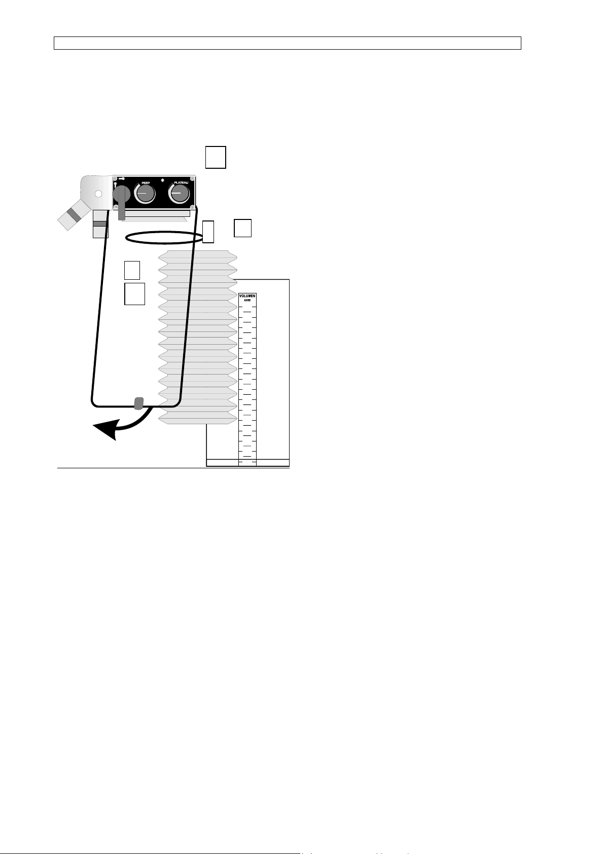
5.1.1 Disassembly
4
3
− Loosen knurled thumb screw (1)
− Pull out patient component
− According to sketch pull off clamps (2)
1500
1400
1300
1200
1100
1000
900
800
700
600
500
400
300
200
100
0
forwards and laterally unhook
− Remove plexiglass cylinder (3)
− Remove bellows (4) and o-ring (5)
5.1.2 Cleaning
Apart from the patient component’s basic unit, all components are to undergo a preliminary
cleaning or preliminary disinfection according to the following procedure.
The components (rubber parts as well) are put in a disinfectant.
After elapse of the recommended time (manufacturer’s recommended time) for effective
disinfection, the parts are to be thoroughly rinsed with clear water.
It is recommeded to thoroughly dry the components to prevent corrosion and the growth of
bacteria.
Rubber parts are not to be cleaned with hard objects.
21
Page 22

OPERATING INSTRUCTIONS Respirator ABV-A / U
5.1.3 Sterilisation
The bellows (4) and the o-ring (5) are to undergo superheated steam sterilisation at 121°C
(glove programme).
The patient component’s basic unit is to be autoclave sterilised at 134°C. A compressed-air
blow gun may not be used for final drying of the basic unit.
5.1.4 Re-assembly
After all parts have been throughly and hygienically cleaned and dried, they can be reassembled in reverse order of their disassembly.
Apply a small amount of lubricant to the threads of the knurled thumb screw (1) before reattaching the patient component.
5.1.5 Front panel and housing of the respirator
At appropriate intervals the front panel and the housing of the respirator module are to be
cleaned with common cleaning liquid (non-aggressive agent). Liquid may not enter the
housing of the respirator.
22
Page 23
OPERATING INSTRUCTIONS Respirator ABV-A / U
6. Calibration
Respiratory pressure gauge of the respirator
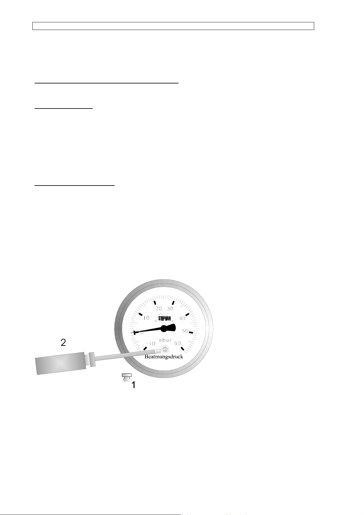
Basic adjustment:
− Close the flow regulator valve at the measuring pipe block.
− Set excessive pressure valve to SP so that the circuit system is pressureless. (or take the
corrugated hose from „RESPIRATOR“)
Procedure for calibration
Remove plastic plug (1) from the calibrating opening in the manometer glass.
With a screw driver turn the calibrating screw until the needle rests at zero. Turning the screw
in the left direction induces the needle to wander to the right.
The respiratory pressure gauge must be replaced should calibration not be possible due to
constant use and wear.
23
Page 24

7. Troubleshooting Guide
Problem Possible cause Correction
OPERATING INSTRUCTIONS Respirator ABV-A / U
Unit’s power switch is not
lit green after activation
Insufficient respiration
pressure
− Cable not connected to
mains supply
− One of primary fuses is
defect (2 x 0,1 AT)
− PLATEAU valve open
− Excessive pressure
valve not in „CL“
postition
− Leakage in circuit
system or patient
component
− Switch lever on patient
component in „manual“
position
− Plug cable into mains
supply
− Check fuses
− Close PLATEAU valve
− Set excessive pressure
valve to „CL“ position
− Check for leakage
− Set lever to „Respirator“
position
Rrespiration pressure
display greatly deviates
from alarm limits on the
pressure monitor
No respiration pressure
„PEEP“ too high
Difference in tidal volume
is > 300 ml
− Pressure supply not
connected (propellant)
− respiration pressure
− Connect pressure
supply
− Adjust to zero
gauge not adjusted
− Volume valve closed − Open volume valve
− PEEP diaphragm sticks
(eg, improper
sterilisation method)
− Leakage in circuit
system
− Excessive pressure
− Have PEEP diaphragm
cleaned by technical
service
− Check for leakage
− Set excessive pressure
valve to „CL“ position
valve not in „CL“ position
24
Page 25

OPERATING INSTRUCTIONS Respirator ABV-A / U
Problem Possible cause Correction
Pressure Monitor
Minimum pressure alarm is
triggered
− Minimum pressure limit
is pre-set too low
− PEEP is over the
minimum pressure limit
− Disconnection on
anesthesia unit (circuit
system)
− Changes in patient
(compliance, resistance,
− Set minimum pressure
limit to over 10 mbar
− Lower PEEP or increase
minimum pressure limit
− Find disconnection and
re-connect
Excessive pressure alarm
is triggered
tubus)
Pressure limit set below
PLATEAU pressure
Pressure limit set below
respiration peak pressure
Change in tubus
Change in Patient
(stenosis)
Reduce PLATEAU
pressure or increase
pressure limit
Reduce respiration
pressure or increase
pressure limit
25
Page 26

OPERATING INSTRUCTIONS Respirator ABV-A / U
8. SPECIFICATIONS
8.1 Respirator module
Dimensions: Width: 530 mm
Height: 120 mm
Depth: 280 mm
Weight: 12 kg
Fuses: 2 x 0.1 A slow-blow.
micro fuse
3 x 20 mm
Power requirements: 220 V / 50 Hz
Power consumption: 18 VA
220 V / 50 Hz
Fuses: 1.25 A slow-blow
micro fuse
5 x 20 mm
Respiration frequency: infinitely variable from 6 to 60 per minute
Respiratory time quotient: variable in stages, Insp:Exp 1:4 - 2:1
Respiration pressure gauge: -10 to 60 mbar
excessive pressure-proof up to 600 mbar
Power failure alarm: acoustic, for at least 40 seconds
26
Page 27
OPERATING INSTRUCTIONS Respirator ABV-A / U
DATA SHEET
1
2
7
8
9
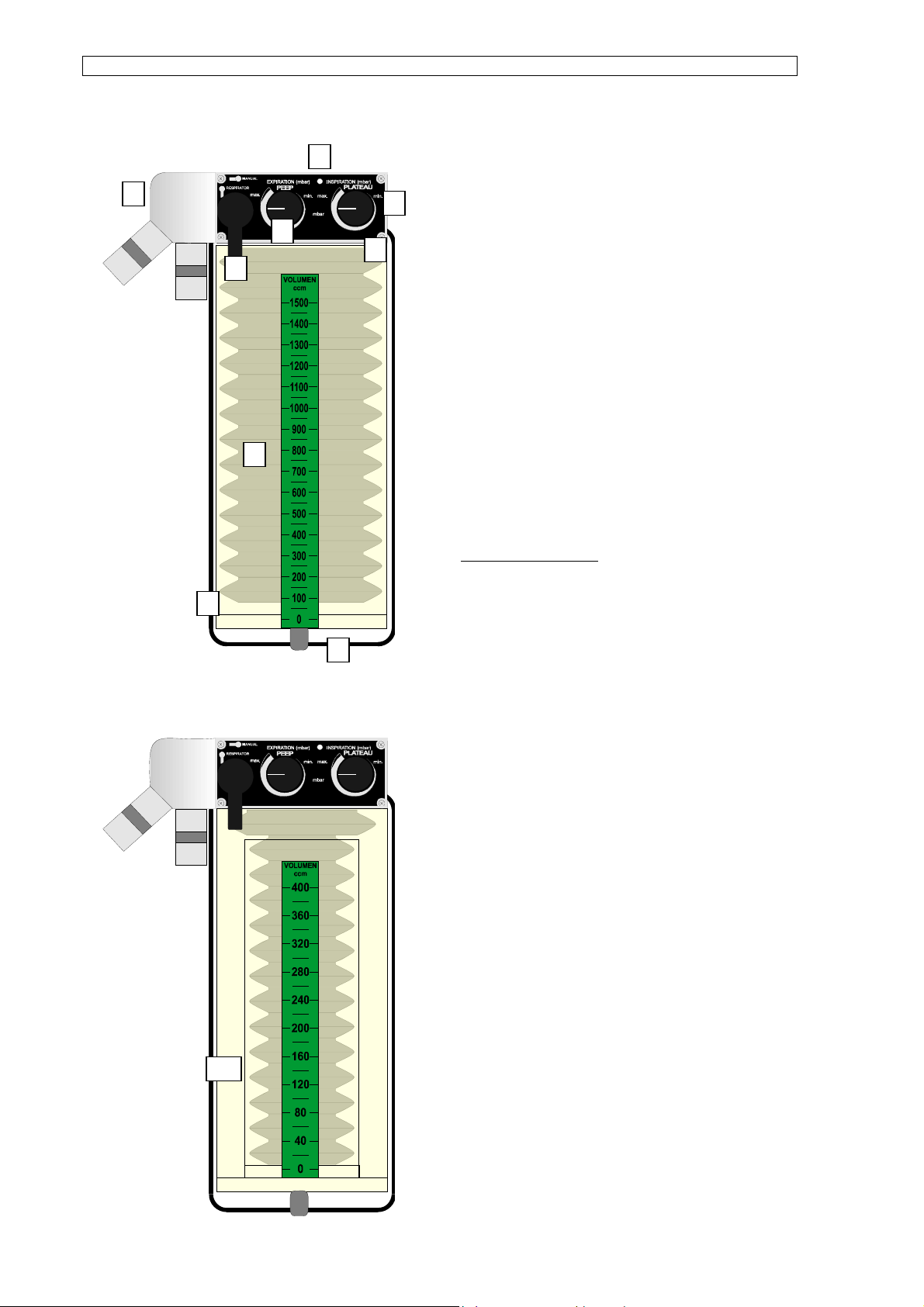
8.2 Patient component
Tidal volume: 0-1500 ml
3
Adult patient component
Tidal volume: 0-400 ml
paediatric patient component
PEEP valve: 0- 10 mbar
4
PLATEAU valve: 10-60 mbar
( upper pressure limit)
Spare Parts List:
5
1. 153 61 016 knurled thumb screw
10
6
2. 153 40 024 basic unit
3. 950 60 020 o-ring
4. 153 61 009 bellows
5. 153 40 014 plexi-bottle
6. 153 40 023 stirrup clamp
7. 926 60 007 adjustment knob
8. 153 42 022 switch lever
9. 153 62 018 front panel
10. 153 61 017 paediatric bottle with
bellows
27
Page 28

OPERATING INSTRUCTIONS Respirator ABV-A / U
DATA SHEET
8.3 Pressure monitor
Measurement range: 0 - 60 mbar
Measurement accuracy: +/- 2%
Measurement principle: piezoresistive pressure absorption gauge
Excess-pressure alarm range: 5 - 60 mbar
Minimum-pressure alarm range: 5 - 25 mbar
Visual alarm
excess pressure LED, red
minimum pressure LED, blinking red
acoustic alarm: electronic signal generator
2 minutes suppressable
28
Page 29

OPERATING INSTRUCTIONS Respirator ABV-A / U
9. Maintenance and Servicing
Medico-technical devices are to undergo, in compliance with MedGV, inspection at regular
intervals.
Such inspections are to be carried out only by authorised personnel (service staff) of the
supplier.
Periodic servicing, semi-annually
The servicing agreement provides the best guarantee which schedules semi-annual
inspections with automatic replacement of components subject to wear.
Servicing carried out by non-technical and unauthorised persons, automatically results in
forfeit of manufacturer’s liability for the safe operation of the device.
29
 Loading...