

Page 1
INSTALLATION AND OPERATOR’S MANUAL
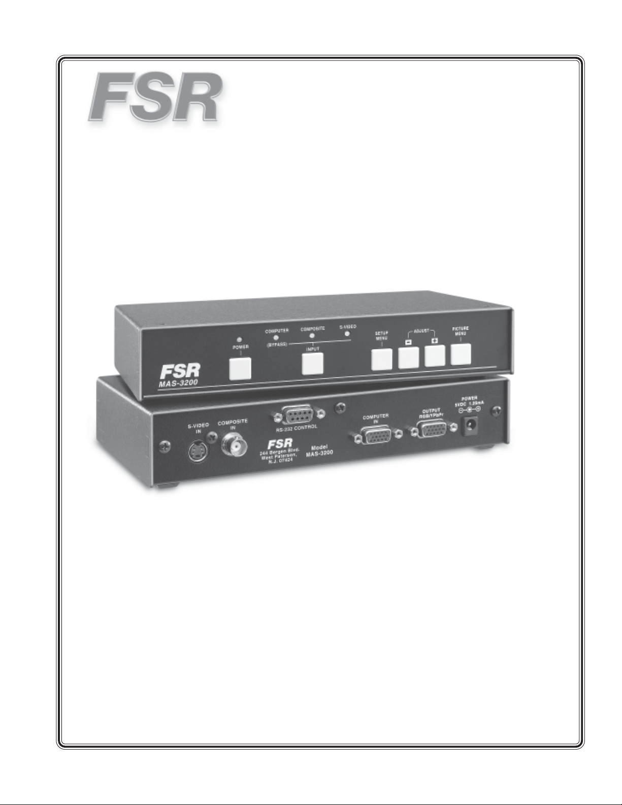
Model MAS - 3200
Video Switcher / Scaler
244 Bergen Boulevard, West Paterson, NJ 07424 • Tel 9737854347 • Fax 9737853318 • Web www.fsrinc.com
11/04 43874 LIT 1034A
Page 2

Operators Safety Summary
The general safety information in this summary is for operating personnel.
Do Not Remove Covers or PanelsThere are no user-serviceable parts within the unit. Removal of the
top cover will expose dangerous voltages. T o avoid personal injury , do not remove the top cover. Do not
operate the unit without the cover installed.
Power SourceThis product is intended to operate from a power source that will not apply more than 230
volts rms between the supply conductors or between both supply conductor and ground. A protective
ground connection by way of grounding conductor in the power cord is essential for safe operation.
Grounding the Product This product is grounded through the grounding conductor of the power cord. T o
avoid electrical shock, plug the power cord into a properly wired receptacle before connecting to the
product input or output terminals. A protective-ground connection by way of the grounding conductor in the
power cord is essential for safe operation.
Use the Proper Power CordUse only the power cord and connector specified for your product. Use only
a power cord that is in good condition. Refer cord and connector changes to qualified service personnel.
Use the Proper FuseT o avoid fire hazard, use only the fuse having identical type, voltage rating, and
current rating characteristics. Refer fuse replacement to qualified service personnel.
Do Not Operate in Explosive Atmospher esT o avoid explosion, do not operate this product in an
explosive atmosphere.
PROPRIETARY INFORMATION
All information in this manual is proprietary to and the property of FSR inc.
This publication is protected by the Federal Copyright Law, with all
rights reserved. No part of this document may be reproduced, transcribed, or
transmitted, in any form or by any means, without prior explicit
written permission from FSR inc.
2 MAS-3200
Page 3

CHAPTER 1
INTRODUCTION
Features
Proper Setup
Package Contents
1
MAS-3200 3
Page 4

Page 5

INTRODUCTION
Y ou have aquired one of the most value packed scaling switchers from FSR. This unit is designed to
convert Composite V ideo and S-V ideo signals to a variety of computer and HDTV resolutions for viewing
on most LCD, Plasma and HDTV displays available today . The MAS-3200 has many advanced features to
enhance performance.
FEATURES
• V ideo inputs are de-interlaced and scaled to the selected PC or HDTV resolution.
• Automatic detection of NTSC or P AL worldwide TV Standards.
• High performance Adaptive 3D Comb Filter .
• Per-pixel motion compensated de-interlacing for artifact-free video images.
• Automatic detection for 3:2 pulldown for 24fps film source material.
• Frame rate conversion of 50Hz to 60Hz for P AL input signals.
• Vertical T emporal (VT) Filter removes jagged artifacts.
• On Screen Display for easy setup and adjustment.
• Built in DCTI/DL TI circuit for Color/Luminance transient improvement.
• PC Input connector for easy integration into an existing system.
• Last memory feature retains the last settings used,
• Control by Front Panel Buttons, RS-232
GETTING THE BEST DISPLAYED IMAGE
There are many factors affecting the quality of results when Composite, or SV ideo signals are up-converted
to computer resolutions. Some basic precautions will ensure the best possible performance from your V ideo
Scaler.
• Output display device – The quality of the output signal will depend largely upon the type and quality of
display device used. For instance, some video projectors just look better than others.
• Distance between the Video Scaler and the display device – This plays a major role in the final
result. Long distances are possible, but special measures should be taken in order to avoid cable losses.
These include using high quality (coax-type) cables or adding cable equalizers, such as the FSR CDA2EQA, CI-5UT , etc.
• Output connection cables – Low quality cables are susceptible to interference. They degrade signal
quality due to poor matching and cause elevated noise levels. Therefore, cables should be of the best
quality . Coax-type computer cables are recommended because of their superior internal shielding
characteristics.
• Interfer ence from nearby electrical devices – These can have an adverse effect on signal quality . For
example, an older computer monitor often emits very high electromagnetic fields that can interfere with the
performance of video equipment in its proximity.
CHECKING THE PACKAGE CONTENTS
The following items are contained in the shipping carton:
MAS-3200 V ideo switching scaler
AC power cable
User manual
MAS-3200 5
Page 6
SPECIFICATIONS
Input
Number 3; 1-Composite, 1 S-Video, 1 Computer V ideo Connector
Connector T ype Composite BNC
S-Video 4 pin mini-DIN
Computer HD-15 Female
V ideo Input Level 1 Vp-p
Computer Input Level 0.7 Vp-p + TTL Sync
Max Computer Resolution 1600x1200
Video S tandards NTSC 3.58, NTSC 4.43, P AL B/G/I/D
User Adjustments Brightness, contrast, hue (NTSC), saturation,detail
Output
Number and T ype 1 RGBHV / Y pBpR (480P, 576P, 720P , or 1080I
Connector HD-15 Female
Level 0.7 Vp-p + TTL Sync
Remote Control
Type RS-232
Connector DB-9 Male
Protocol See Chapter 3
Power Source 5VDC, 2 Amp universal input power supply
Size 1/2 RU
W eight 1.8 lbs
6 MAS-3200
Page 7

CHAPTER 2
INSTALLATION
Video Inputs
Video Outputs
Front Panel Controls
2
MAS-3200 7
Page 8

8 MAS-3200
Page 9
CONNECTING THE HARDWARE
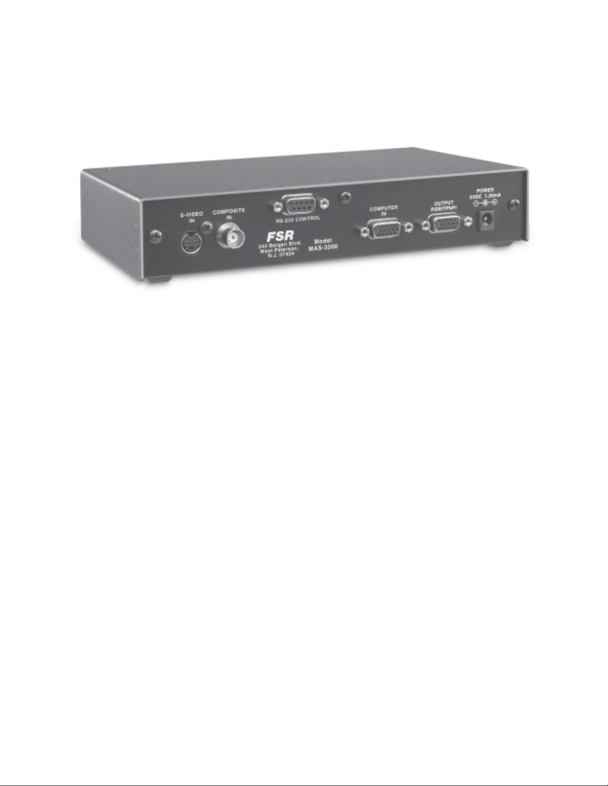
The first step is to connect a video source to the input of the MAS-3200 and to connect its
output to a display device. Below is a photograph of the rear panel of the unit.
Connecting the V ideo Inputs
The V ideo Scaler can accept a Composite V ideo, or S-V ideo input signal for scaling, as well as a computer
signal input that can be passed through.
• Composite V ideo - use a BNC cable to connect the Composite V ideo output of the source equipment to
the connector labeled “VIDEO” on the back of the unit.
• S-Video - use an S-V ideo cable to connect the S-V ideo output of the source video equipment to the
connector labeled “S-VIDEO” on the back of the unit. S-Video provides improved performance over
Composite V ideo and is recommended whenever possible.
• PC V ideo - connect the source computer’s VGA output signal to the HD15 connector labeled “PC IN”
on the back of the unit. Note – This PC Input Signal is not scaled, but is available for pass-through when
the PC Source is selected.
Connecting the V ideo Output
Connect the MAS-3200's output to the destination display device, such as an LCD computer monitor,
video projector, HDTV Set or other device, via the HD15 connector on the back labeled “OUTPUT”.
Connecting Power to the Unit
The SC-1250 can accept 100-240VAC@50-60Hz. When the unit’ s front panel Power
Switch is turned On, the Power LED indicator on the front will illuminate.
MAS-3200 9
Page 10

FRONT PANEL CONTROL
The MAS-3200 is controlled via Front Panel Buttons and status is indicated by the OSD (on screen
display).
Mode Button
Press the Mode Button repeatedly to toggle through the following controls, as shown on the OSD (On
Screen Display) of the video display connected to the output of the unit.
• Source Mode: While in this mode, press the + or – Button to choose the desired input source from:
Video, S-V ideo or Component V ideo.
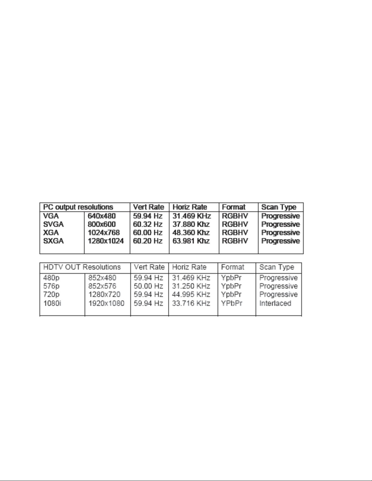
• Resolution Mode: If the output is selected as RGB, press + or – Button to choose the output resolution
from: VGA, SVGA, XGA or SXGA for PC output.
• Output Mode: Press + or – Button to select either PC (RGB) or HDTV (YPbPr) out.
• Aspect Mode: Press + or – Button to choose between Standard Aspect (4:3) and W ide Aspect (16:9)
output.
• Enhancement: Turn the 3D Comb Filter function On or Off by with the + and - Buttons. Note – When
VCR or non-standard video source is connected to the input, the output picture may jitter. If this occurs,
please turn off the 3D Enhance function.
• Digital NR Mode: T urn the Digital Noise Reduction function On or Off by using the + and – Buttons.
Picture Button
Press the Picture Button repeatedly to toggle through the following picture adjustment
parameters, then use the + and – Buttons to adjust the level.
• Contrast: The range of this adjustment is 0~48. The Factory Default is 40.
• Bright: The range of this adjustment is 0~48. The Factory Default is 24.
• Saturation: The range of this adjustment is 0~48. The Factory Default is 24.
• Hue: (NTSC Only) The range of this adjustment is 0~48. The Factory Default is 24.
• Detail: The range of this adjustment is 0~48. The Factory Default is 10.
Input Button
Press the Input Button to toggle through the input sources.
+ and - Buttons
Press these buttons for control or to set values as described above.
10 MAS-3200
Page 11

Power LED and Button
The Power LED illuminates when the unit has power on.
Factory Reset
When in the Picture Adjust Mode (5.2), simultaneously pressing and holding the + and –
Buttons for 5 seconds returns the unit to all the Factory Default settings.
MAS-3200 11
Page 12

12 MAS-3200
Page 13

CHAPTER 3
REMOTE CONTROL PROTOCOL
RS 232
Transmission Format
Command Codes
3
Response Codes
MAS-3200 13
Page 14

14 MAS-3200
Page 15

RS-232 REMOTE CONTROL PROTOCOL
RS-232 TRANSMISSION FORMA T
Baud Rate: 9600 bps
Data Bit: 8 bits
Parity: none
Stop Bit: 1 bit
Note - The connection between the video scaler and the remote controller requires an RS-232 modem
cable
V ideo Scaler Remote Controller
PIN Definition PIN Definition
1 NC 1 NC
2 TxD 2 RxD
3 RxD 3 TxD
4 NC 4 NC
5 GND 5 GND
6 NC 6 NC
7 NC 7 NC
8 NC 8 NC
9 NC 9 NC
RS-232 COMMAND CODES
The command and Response codes are a combination of 3 bytes. The first and second bytes are text and
the third byte is a HEX value. No carraige return is necessary .
Remote Controller Command Codes
Code Comment
‘PW’+0 power off (standby)
‘PW’+1 POWER power on (normal)
‘IN’+0 Composite video
‘IN’+1 S video
‘IN’+2 Not Used
‘IN’+3 INPUT PC bypass
‘OU’+0 VGA
‘OU’+1 480p
‘OU’+2 SVGA
‘OU’+3 XGA
‘OU’+4 SXGA
‘OU’+5 576p
‘OU’+6 720p
‘OU’+7 OUTPUT 1080i
‘OS’+0 OSD osd OFF
‘OS’+1 osd ON
‘DI’+0 display OFF
‘DI’+1 DISPLA Y display ON
MAS-3200 15
Page 16

‘BR’+value brightness value = 0~48
‘CO’+value contrast value = 0~48
‘SA’+value saturation value = 0~48
‘SH’+value detail value = 0~48
‘TI’+value hue value = 0~48
‘RE’+0 reset video adjustment reset
‘FP’+0 front panel lockout ON
‘FP’+1 PANEL front panel lockout OFF
‘TD’+0 3 D enhance OFF
‘TD’+1 Three D 3 D enhance ON
‘NR’+0 Digital NR OFF
‘NR’+1 NR Digital NR ON
‘AS’+0 aspect 16:9
‘AS’+1 ASPECT aspect 4:3
retrive video scaler all status
‘PW’+? ‘IN’+? ‘OS’+?
‘AL’+0 ‘OU’+? ‘DI’+? ‘IR’+?
‘FP’+? ‘BR’+? ‘CO’+?
‘SA’+? ‘SH’+? ‘TI’+?
‘TD’+? ‘NR’+? ‘AS’+?
16 MAS-3200
Page 17

CHAPTER 4
WINDOWS CONTROL PANEL
Set up
Normal Operation
Settings
4
MAS-3200 17
Page 18

18 MAS-3200
Page 19

SETUP
T o setup the windows control panel, insert the MAS-3200 CD-ROM into the drive. If your computer is set
for auto run the setup program will automatically start. If not open the CD drive and double click on
Setup.exe. Follow the directions and the program will be installed in\Program Files\FSR\MAS-3200
directory . The setup program will place a shortcut on the desktop, clicking on the shortcut will run the
program.
NORMAL OPERATIONS
When the windows Control Panel comes up the following screen will be displayed:
The screen is divided into two sections,Sources and Output Resolutions. Clicking on the Composite button
sends a message to the MAS-3200 that makes the Composite Source the current source. Pressing the SVideo, or Computer V ideo, makes S-V ideo or Computer Video sources active.
Pressing settings will display the following screen:
MAS-3200 19
Page 20

SETTINGS
The settings are divided into three sections, V ideo Settings, Adjustments, and Serial Port. To revert back to
the main screen, press the settings button again.
Video Settings
Brightness, Detail(sharpness), Contrast, Hue (tint), and Saturation, are adjustable by moving the button on
the appropriate slider.
Reset returns the video settings to their original settings.
Adjustments
Digital NR (noise reduction), Aspect, Enhancement, OSD (on screen display), Front Panel Lock, and
Display can be enabled or disabled in this section.
Digital NR Turns on/off the Digital Noise Reduction function.
Aspect Choose between Standard Aspect (4:3), OR wIDE aSPECT (16:9)
Enhancement Turns on/off the 3D Comb Filter . Note: If a VCR or other non-standard video source is
connected to the input the output picture may jitter . If this happens turn off enhancement.
OSD Turns on/off the On Screen Display .
Display Turns on/of f the resolution display.
Front Panel Lock Locks/unlocks the front panel buttons.
20 MAS-3200
Page 21

CHAPTER 5
TROUBLESHOOTING
5
MAS-3200 21
Page 22

22 MAS-3200
Page 23

9 TROUBLESHOOTING
If the recommended actions listed below do not result in satisfactory operation, please consult the FSR
T echnical Support Department or your equipment Dealer.
Problem and Possible Solution
No picture on the output monitor
If the LED is illuminated, check that there is a correct V ideo Input signal and that the display device
connected to the output is switched on and set to the correct input and its Brightness and Contrast are set
correctly.
Colors appear wrong on the output monitor
Try adjusting the Color , Tint, Contrast and Brightness settings on your display . These are usually set up for
viewing computer images, which may be somewhat different from viewing images that have
beenupconverted from video. Make sure your output cable assembly is not faulty , which could prevent
either the Red, Green or Blue signal from being passed through the cable.
T oo much smearing
Smearing usually occurs when a Composite V ideo input is used and is generally unavoidable, unless you can
switch to using S-V ideo. Using good quality video cable will help towards reducing this affect.
Smearing that may not be noticeable on a small video monitor may become objectionable on a large screen
video projector.
No color on the output monitor , only a black and white image
Check the condition of the cables being used. A faulty S-V ideo cable can often cause a black and white
image. Ensure that the color controls on your computer monitor or video projector are all set correctly .
Ensure that the color adjustment on the V ideo Scaler is not adjusted completely down. It may be necessary
to reset the video levels by pressing the + and – Buttons simultaneously .
MAS-3200 23
Page 24

24 MAS-3200
Page 25

CHAPTER 6
MISCELLANEOUS
Regulatory Compliance
Warranty
6
Service
MAS-3200 25
Page 26

26 MAS-3200
Page 27

REGULATORY COMPLIANCE
The Video Scaler has been tested for compliance with: FCC.
The Power Supply has been tested for compliance with: UL, CSA,and CE.
WARRANTY POLICY
This product is warranted against failures due to defective parts or faulty workmanship for a period of one year
after delivery to the original owner. During this period, FSR will make any necessary repairs or replace the unit
without charge for parts or labor. Shipping charges to the factory or repair station must be prepaid by the owner,
return-shipping charges, via UPS / FedEx ground, will be paid by FSR.
This warranty applies only to the original owner and is not transferable. In addition, it does not apply to repairs
done by other than the FSR factory or Authorized Repair Stations.
This warranty shall be cancelable by FSR at its sole discretion if the unit has been subjected to physical abuse
or has been modified in any way without written authorization from FSR. FSR’s liability under this warranty is
limited to repair or replacement of the defective unit.
FSR will not be responsible for incidental or consequential damages resulting from the use or misuse of its
products. Some states do not allow the exclusion of incidental or consequential damages, so the above limitations may not apply to you. This warranty gives you specific legal rights, and you may also have other rights
which vary from state to state.
Warranty claims should be accompanied by a copy of the original purchase invoice showing the purchase date
(if a Warranty Registration Card was mailed in at the time of purchase, this is not necessary). Before returning
any equipment for repair, please read the important information on service below.
SERVICE
Before returning any equipment for repair, please be sure that it is adequately packed and cushioned against
damage in shipment, and that it is insured. We suggest that you save the original packaging and use it to ship the
product for servicing. Also, please enclose a note giving your name, address, phone number and a description of
the problem.
NOTE: all equipment being returned for repair must have a Return authorization (RMA) Number. To get a
RMA Number, please call the FSR Service Department (973-785-4347). Please display your RMA Number
prominently on the front of all packages.
CONTACT INFORMATION
244 Bergen Blvd.
West Paterson, NJ 07424
Phone: (973) 785-4347
*Order Desk Fax: (973) 785-4207
E-mail:
sales@fsrinc.comsales@fsrinc.com
sales@fsrinc.com
sales@fsrinc.comsales@fsrinc.com
Web Site: http://www.fsrinc.com
MAS-3200 27
Page 28

28 MAS-3200
 Loading...