

Page 1
Operating Guide
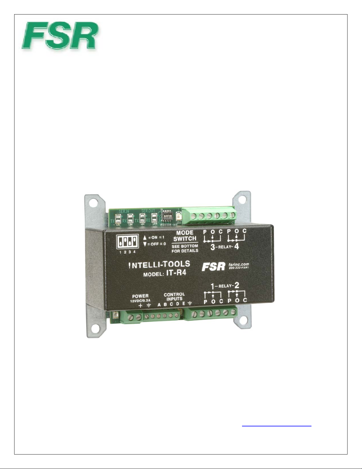
INTELLI-TOOLS
IT- R4
Switch or Logic Level Controlled Relay Module
244 Bergen Blvd West Paterson NJ 07424 1-800-332-FSR1 http://www.fsrinc.com/
43924 LIT1222C
Page 2

Warranty Policy
This product is warranted against failures due to defective parts or faulty workmanship for a period of five years after delivery to the
original owner. During this period, FSR will make any necessary repairs or replace the unit without charge for parts or labor. Shipping
charges to the factory or repair station must be prepaid by the owner, return-shipping charges, via UPS / FedEx ground, will be paid
by FSR.
This warranty applies only to the original owner and is not transferable. In addition, it does not apply to repa irs done by other than the
FSR factory or Authorized Repair Stations.
This warranty shall be cancelable by FSR at its sole discretion if the unit has been subjected to physical abuse or has been modified in
any way without written authorization from FSR. FSR’s liability under this warranty is limited to repair or replacement of the
defective unit.
FSR will not be responsible for incidental or consequential damages resulting from the use or misuse of its products. Some states do
not allow the exclusion of incidental or consequential damages, so the above limitations may not apply to you. This warranty gives
you specific legal rights, and you may also have other rights which vary from state to state.
Warranty claims should be accompanied by a copy of the original purchase invoice showing the purchase date (if a Warranty
Registration Card was mailed in at the time of purchase, this is not necessary). Before returning any equipment for repair, please read
the important information on service below.
SERVICE
Before returning any equipment for repair, please be sure that it is adequately packed and cushioned against damage in shipment, and
that it is insured. We suggest that you save the original packaging and use it to ship the product for servicing. Also, please enclose a
note giving your name, address, phone number and a description of the problem.
NOTE: all equipment being returned for repair must have a Return authorization (RMA) Number. To
get a RMA Number, please call the FSR Service Department (973-785-4347). Please display your RMA
Number prominently on the front of all packages.
CONTACT INFORMATION
FSR Inc.
244 Bergen Blvd.
West Paterson, NJ 07424
Phone: (973) 785-4347
*Order Desk Fax: (973) 785-4207
E-mail: sales@fsrinc.com
Web Site: http://www.fsrinc.com
2
Page 3

Table of Contents
Warranty Policy.............................................................................................................................. 2
Table of Contents............................................................................................................................ 3
IT-R4 Mechanical........................................................................................................................... 4
Product Overview........................................................................................................................... 5
Features........................................................................................................................................... 5
Applications.................................................................................................................................... 5
Typical Application ........................................................................................................................ 6
Caution:........................................................................................................................................... 6
Setup ............................................................................................................................................... 7
Switch Input Actuation Table......................................................................................................... 7
Mode Switch Label......................................................................................................................... 8
Single Relay Interlock Mode (SPDT) Mode Switch Setting 000............................................. 8
Multiple Relay Activation – Alternate Action Mode Switch Setting 001............................... 8
Multiple Relay Activation – Momentary ON Mode Switch Setting 010................................. 8
Dual Relay Mode (DPDT) - Push On/Push Off Mode Switch Setting 011............................. 8
Dual Relay Modes (DPDT) - Alternate Action Mode Switch Setting 100 ........................... 8
Dual Relay Modes (DPDT) Alternate Pulsed 0.25 sec Mode Switch Setting 101.................. 8
Quad Relay Mode Mode Switch Setting 101 ....................................................................... 9
Special Function Mode Mode Switch Setting 111 ................................................................. 9
Mode Dipswitch 4........................................................................................................................... 9
IT-R4 Specifications..................................................................................................................... 11
3
Page 4
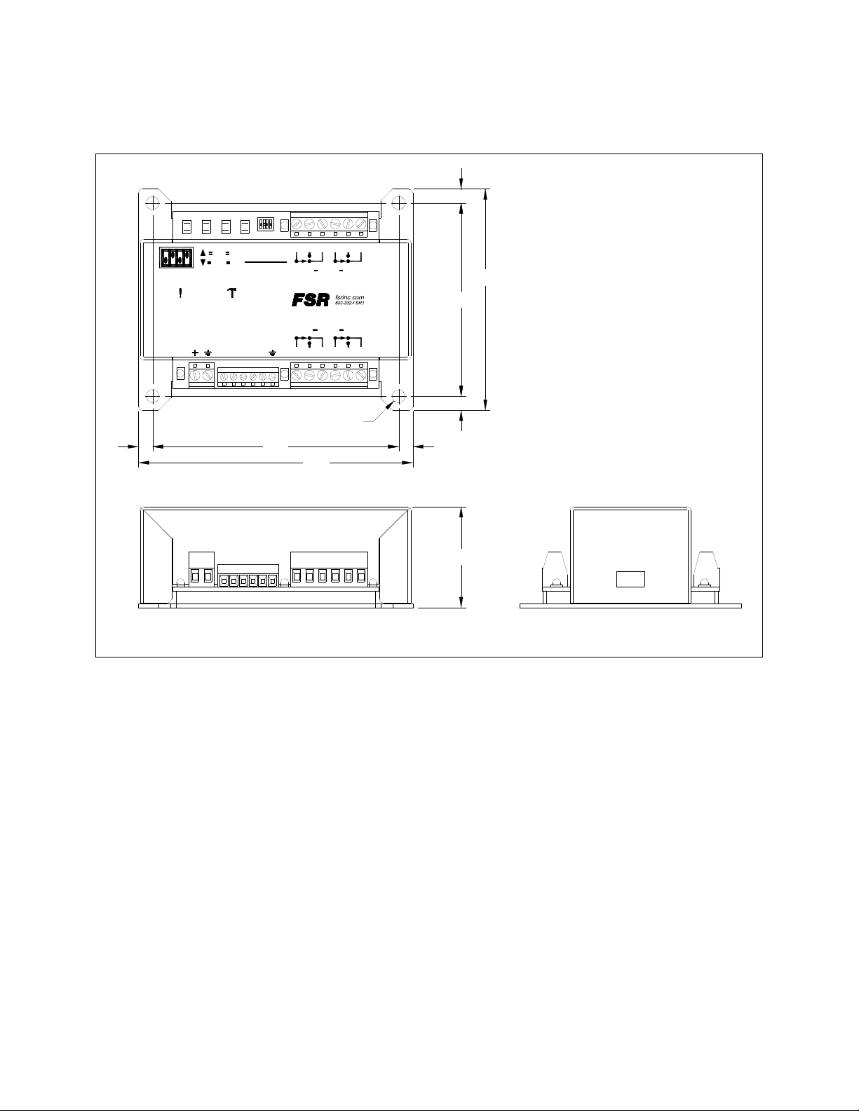
IT-R4 Mechanical
.22
POCPOC
MODE
ON 1
SWITCH
OFF 0
11234
NTELLI- OOLS
POWER
12VDC/0.2A
CONTROL
A
B
SEE BOTTOM
FOR DETAILS
IT-R4MODEL:
INPUTS
C
ED
RELAY
34
RELAY
2
1
POCPOC
4x .203 DIA.
3.44
3.00
.22
3.81
.22.22
4.25
1.57
4
Page 5

Product Overview
The IT-R4 is a multi-purpose switch or logic level activated Relay Module. Four user configured relays are
activated and controlled via five input ports that are designed to accept either a switch contact closure or logic
level input. A four position configuration dip switch sets the operating behavior of the relays. Each relay can be
set for different operating modes; “On, “Off”, pulsed for a ¼ of a second or toggled which changes the relay to
the opposite state. For a detailed description of operation and settings see the Switch Input Actuation Table.
Features
One module does the work of many
Quick easy setup and configuration
Small footprint
High quality relays
Quick connect terminals
Integral mounting plate
Applications
Shade and Screen Control (via Relay interface module).
Logic Level Control
Relay Contact Closure
Speaker Muting
Relay remote Control
5
Page 6

Typical Application
SPEAKER
MUTE
TO AC POWER - AC
ADAPTER SOLD
SEPARATELY
MODEL: IT-PS1
FSR PN: 16805
KEYPAD
INPUT
RELAY CONTACT
CLOSURE FOR LIGHTING
1123 4
NTELLI- OOLS
POWER
12VDC/0.2A
ON 1
OFF 0
A
SWITCH
SEE BOTTOM
FOR DETAILS
IT-R4MODEL:
CONTROL
INPUTS
C
B
MODE
ED
LOW VOLTAGE
CONTROL
INTERFACES
POCPOC
RELAY
34
RELAY
2
1
POCPOC
LOGIC LEVEL
CONTROLLED DEVICE
STAGE/SCREEN
CONTROL
Caution:
The IT-R4 and IT-R4S relay interface modules are not intended to directly switch AC line voltages.
Connection to lighting and shade and screen systems should be done at the low voltage control interface
provided by the manufacturer.
If you must interface to AC line voltages, add a relay module designed for this purpose such as the FSR 12 Volt
AC-2 or 12 volt AC-2A.
6
Page 7

Setup
The four relays can be configured as indicated in the relay configuration portion of this table along with their
corresponding relay operation. The label is located on the bottom of the unit. The operation of the relays is
accomplished by combining one of the five inputs of either A, B, C, D or E with a selected setting on a fourposition configuration dipswitch located on the main PCB. Switches S1 through S3 are used for accomplishing
this, while the fourth position is used to control the logic state at which the relays will operate. S4 closed allows
active low inputs to turn on the relay while S4 open allows active high inputs to turn on the relay.
Switch Input Actuation Table
Switch Inputs A-E
Configuration /
Mode Dipswitches
Control Inputs (A-E) Acceptable Input Level from an
external device that is edge
triggered.
24V Max
+V
Switch Possibilities:
1 = Gnd
0 = +V to operate (2-24V)
2V Min
Falling Edge Rising Edge
Or
1V Max
-1V Min
24V Max
2VMIn
7
Page 8

Mode Switch Label
1=
0=
Single Relay Interlock Mode (SPDT) Mode Switch Setting 000
This mode provides the ability to control each of the four SPDT relays through switch inputs A through D.
When one relay is activated or turned on, the other relays are turned off. For example if the user turns on Relay
#1 using switch input “A”, then Relays 2, 3 and 4 are turned off. Switch input E turns off all Relays.
Multiple Relay Activation – Alternate Action Mode Switch Setting 001
This mode toggles each individual Relay on or off. The first switch closure turns the relay on and the second
switch closure turns the relay off. Any combination of switches may be activated at the same time. Switch input
E, when activated, overrides all other switch inputs and turns off all relays.
Multiple Relay Activation – Momentary ON Mode Switch Setting 010
This mode turns on the corresponding relay for the duration of the switch closure. Switch E turns on all relays
for the duration of the closure. Any number of relays can be operated at the same time.
Dual Relay Mode (DPDT) - Push On/Push Off Mode Switch Setting 011
This mode provides the ability to pair up the Relays for use in a Dual Relay application. Each pair R1/R2 and
R3/R4 effectively become DPDT relays when configured in this mode. Switch A turns on relays 1 & 2; Switch
B turns off relays 1 & 2. Switch C turns on relays 3 & 4, and switch D turns off relays 3 & 4. Switch E turns
off all relays.
Dual Relay Modes (DPDT) - Alternate Action Mode Switch Setting 100
This mode provides the ability to toggle each pair of Relays. Switch “A”, toggles relay pair R1/R2 and Switch
C toggles relay pair R3/R4. Switch D unconditionally turns on both pairs of relays and switch E
unconditionally turns off both pairs.
Dual Relay Modes (DPDT) Alternate Pulsed 0.25 sec Mode Switch Setting 101
This mode provides the ability to pulse each relay for a given application that may require the use of a trigger
pulse for turning on some type equipment.
• Switch A the first press sends a ¼ second pulse to relay 1; the second press sends a ¼ second pulse to
relay 2.
8
Page 9

• Switch B when pressed sends a ¼ second pulse to relay 1 on the leading edge; when released it sends a
¼ second pulse to relay 2 on the trailing edge.
• Switch C the first press sends a ¼ second pulse to relay 3; the second press sends a ¼ second pulse to
relay 4.
• Switch D when pressed sends a ¼ second pulse to relay 3 on the leading edge; when released sends a ¼
second pulse to relay 4 on the trailing edge.
• Switch E has no function.
Quad Relay Mode Mode Switch Setting 101
This mode provides the ability to turn on or off all four Relays at once.
Switch A turns on all relays, Switch B turns off all relays, and Switch C toggles all relays. Switch inputs D & E
have no functions.
Special Function Mode Mode Switch Setting 111
• Switch A turns relays 1 & 2 on and sends ¼ second pulse to relay 3.
• Switch B turns relays 1 & 2 off, and sends ¼ second pulse to relay 4.
• Switch C first press turns on relays 1 & 2 and pulses relay 3 for ¼ second. The second press turns off 1
& 2, and pulses relay 4 for ¼ second.
• Switch D the leading edge performs Switch A function, trailing edge performs Switch B function.
Mode Dipswitch 4
Mode Switch 4 determines the control activation state of the 4 relays.
• S4 set to “1”: Inputs A thru E are active Low. The leading edge is the High to Low transition of the
switch input. The trailing edge is the Low to High transition of the switch input.
• S4 set to “0”: Inputs A thru E are active High. The leading edge is the Low to High transition of the
switch input. The trailing edge is the High to Low transition of the switch input.
9
Page 10

10
Page 11

IT-R4 Specifications
Relay Ratings
Relay Contact material Ag alloy
Max. Switching voltage 50 VAC, 30 VDC
Max. Switching current 5 A (NO)/3 A (NC)
Max. Switching capacity
Min. permissible load 10 mA @ 5 VDC (for contact cleaning)
Switch Input Characteristics
Input Voltage
Input Impedance: 7k
Minimum Actuation Time to
recognize a valid switch input
Power
Power supply
NO: 250 VA (AC), 150 W (DC Resistive) NC:
150 VA (AC), 90 W (DC Resistive)
Logic High range: 2.0 – 24V
Logic Low range: -1.0 - +1.0V
0.1 Sec
12 VDC @ 160mA fully loaded. FSR IT-PS1
#16805 may be ordered separately
Mechanical and Environmental
Connectors Screw terminals
Overall dimensions (see drawing
for details)
Shipping weight 0.9 lbs.
Ambient temperature 0 to 50°C
Ambient humidity 5% to 95% non-condensing
4.25”L x 3.44” W x 1.57” H
Accessories
12VDC Relay interface module
FSR16981 AC-2 (SPDT) or 16982 AC-2A
(DPDT)
11
 Loading...