

Page 1
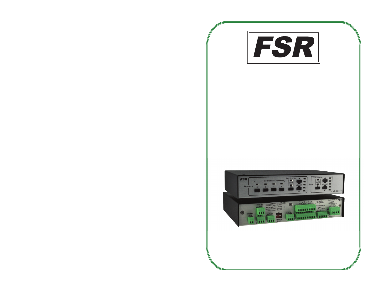
IT-AS411 SERIES
AUDIO SWITCHER / AMPLIFIERS
(COVERS MODELS IT-AS411, IT-AS411-25M70 AND IT-AS411-25S8)
INSTALLATION AND OPERATING GUIDE
(MODEL IT-AS411-25S8 pictured)
16
43961
LIT1354
Page 2

PROPRIETARY INFORMATION
All information in this manual is proprietary to and the
property of FSR inc. This publication is protected by the Federal
Copyright Law, with all rights reserved. No part of this document
may be reproduced, transcribed, or transmitted, in any form or
by any means, without prior explicit written permission from FSR
Inc.
Operators Safety Summary
The general safety information in this summary is for operating
personnel.
REGULATORY COMPLIANCE
The Power Adapter has been tested for compliance with: UL, CSA and CE.
WA R R A N T Y P OL IC Y
This product is warranted against failures due to defective parts or faulty workmanship for a period
of three years after delivery to the original owner. During this period, FSR will make any necessary
repairs or replace the unit without charge for par ts or labor. Shipping charges to the factory or repair
station must be prepaid by the owner, return-shipping charges, via UPS / FedEx ground, will be
paid by FSR.
This warranty applies only to the original owner and is not transferable. In addition, it does not apply
to repairs done by other than the FSR factory or Authorized Repair Stations.
This warranty shall be cancelable by FSR at its sole discretion if the unit has been
subjected to physical abuse or has been modi fi ed in any way without wr itten authorization from FSR.
FSR’s liabilit y under this warranty is limited to repair or replacement of the defective unit.
Read Instructions Read and understand all safety and operating
instructions before using this equipment. Keep the instructions
handy.
Do Not Remove Covers or Panels There are no user-serviceable
parts within the unit. Removal of the top cover will expose
dangerous voltages. To avoid personal injury, do not remove the
top cover. Do not operate the unit without the cover installed.
Power Source This product is intended to operate from the
specifi ed wall plug-in transformer. Do not use any other power
source.
Use the Proper Power Cord Use only the power cord and
connector specifi ed for your product. Use only a power cord that is
in good condition. Refer cord and connector changes to qualifi ed
service personnel.
Do Not Operate in Explosive Atmospheres To avoid explosion,
do not operate this product in an explosive atmosphere.
FSR will not be responsible for incident al or consequential damages resulting from the use or misuse
of its products. Some states do not allow the exclusion of incidental or consequential damages, so the
above limitations may not apply to you. This warranty gives you specifi c legal rights, and you may
also have other rights which vary from state to state.
Warrant y claims should be accompanied by a copy of the original purchase invoice
showing the purcha se date (if a Warrant y Registration Card was mailed in at the time of pu rchase, this
is not necessary). Before returning any equipment for repair, please read the impor tant information
on service below.
SERVICE
Before returning any equipment for repair, please be sure that it is adequately packed and cushioned
against damage in shipment, and that it is insured. We suggest that you save the original packaging
and use it to ship the product for ser vicing. Also, please enclose a note giving your name, address,
phone number and a description of the problem.
NOTE: All equipment being returned for repair must have a Return Authorization ( RMA)
Number. To get a RMA Number, please call:
FSR Service Department (973-785-4347).
Please display your RMA Number prominently on the front of all packages.
Contact Information:
FSR Inc.
244 Bergen Boulevard,
Woodland Park, NJ 07424
Tel: (973) 785-4347 · Fax: (973) 785-4207
E-Mail: sales@fsrinc.com · Web: http://www.fsrinc.com
2
15
Page 3
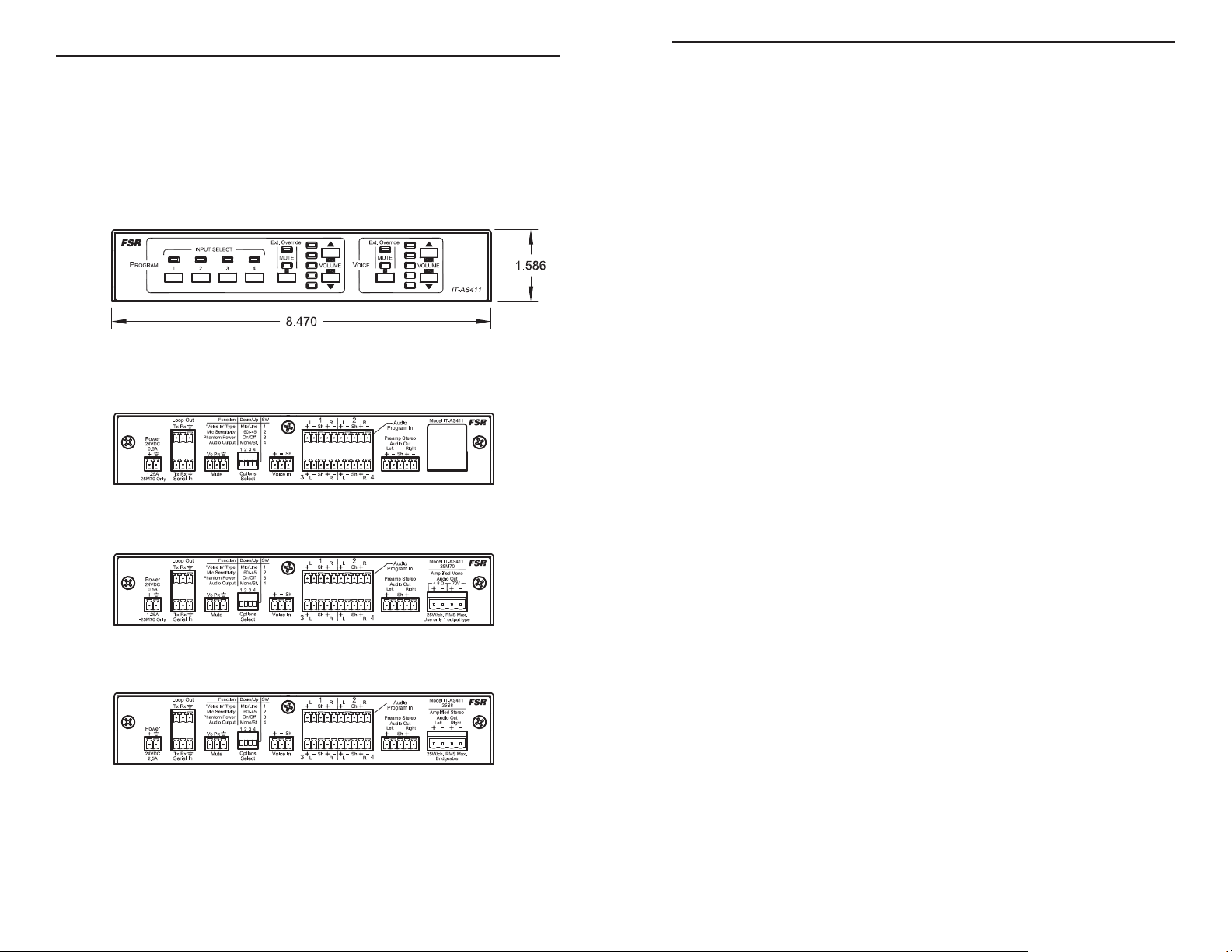
DIMENSIONS
All models have the same front panel appearance.
The depth on all models is 6”. Allow clearance for connectors and
cables.
INTRODUCTION
The IT-AS411 Series Audio Switchers are 4x1 audio switchers that
have an extra line/mic level input for a voice lift system or direct
microphone input. All models have four switched line level inputs
and an independent mic or line level input that is summed (mixed)
with the selected active program audio. Automatic gain control
and noise gating are incorporated to ensure consistent voice and
program audio levels with a minimum of unwanted ambient noise.
All models have balanced or unbalanced input and output
capability. DIP switches are provided to set the voice input level to
mic or line, adjust microphone sensitivity, set phantom power and
select mono or stereo operation. They also have adjustable volume
control buttons and mute for both the program and voice inputs.
Switching, muting and gain can be executed locally by front panel
push buttons, muting by external dry contact closure and additional
commands via RS-232 serial control. On board LED’s monitor;
input select, volume levels and muting status.
All models have line level inputs and outputs. They can be
controlled by the front panel and via pass through RS-232 control.
14
The IT-AS411-A25M70 features a 25Wrms mono internal amplifi er
to drive either a 4 to 8 ohm speaker or a 70V line output.
The IT-AS411-A25S8 features a 25Wrms stereo output to drive a 4
to 8 ohm speaker.
3
Page 4

FEATURES:
POWER REQUIREMENTS IT-AS411 IT-AS411-25M70 IT-AS411-25S8
Power input requirement 24VDC @ 0.5A 24VDC @ 1.25A 24VDC @ 2.5A
• Mic / line level voice lift input
• Program audio / voice lift mixing
• Program audio inputs and outputs
• Serial control with serial pass-through
• Terminals for remote muting of voice and/or program audio
via dry contact closure
• On board LED’s monitor; input select, volume level and
muting status
• Current limited remote LED output terminal for program
audio and voice (mute) status
• Integrated audio amplifi ers on A25-M70 and A25-S8 models
• Program audio trim (gain)
• Automatic gain control and noise gating
• Preamplifi er output
Model Dimensions (inches) Shipping weight.
MECHANICAL
ACCESSORIES DESCRIPTION
RK-1 Front accessible rack mount kit
RK-2 Shelf style rack mount kit
IT-AS411
IT-AS411-25M70
IT-AS411-25S8
8.5 x 5.875 x 1.5625 4 lbs.
4
13
Page 5

TECHNICAL SPECIFICATIONS
TYPICAL APPLICATION
PROGRAM AUDIO
IT-AS411
IT-AS411-25M70 IT-AS411-25S8
INPUT
Input 4, Stereo balanced/unbalanced
Connector type Pluggable screw terminal
Maximum Input Level 7.5dBV
Input Sensitivity NA
-20dBv with 8Ω or 70V
load
-20dBv with 8Ω
load
Input Impedance 20kΩ balanced/unbalanced
MICROPHONE INPUT IT-AS411 IT-AS411-25M70 IT-AS411-25S8
Input 1
Connector type Pluggable screw terminal
“Voice In” type Microphone/Line
Microphone Sensitivity -43/-35dB
Maximum Input Level 1dBV
Low cutoff 200Hz
Phantom power 24V
PRE-AMP AUDIO
IT-AS411 IT-AS411-25M70 IT-AS411-25S8
OUTPUT
Connector type Pluggable screw terminal
Number of outputs 1 Stereo or 2 Mono (L + R program audio input summed)
Signal Output Balanced/unbalanced
Frequency Response 20Hz – 20kHz (+/- 0.5dB)
THD + N <0.09% @ 1kHz; 11dBV with 600Ω load (balanced)
Signal to Noise Ratio >80dB @ 1kHz; rated output (unweighted)
Output Impedance 50Ω
11234
NTELLI- OOLS
POWER
12VDC/0.2A
MODEL:
POCPOC
MODE
ON 1
SWITCH
OFF 0
SEE BOTTOM
34
FOR DETAILS
IT-R4
1
CONTROL
INPUTS
POCPOC
A
B ED
C
POWER CORD
RELAY
fsrinc.com
800-332-FSR1
RELAY
2
FSR IT-R4S OR
OTHER SERIAL
(INCLUDED)
PC
CONTROLLED
DEVICE
Power
+
24VDC
2.5A
RS 232 CONTROL
Function SW
Loop Out
'Voice In' Type
Rx
Tx
Mic Sensitivity
Phantom Power
Audio Output
Vo
P
R
Rx
Tx
Mute
Serial In
MUTE SWITCHES
TUNER
Down/Up
1
Mic/Line
-60/-45
2
On/Off
3
Mono/St.
4
1234
Sh
-
+
Options
Voice I n
Select
OR
MIC OR VOICE
LIFT SYSTEM
DVD/BLU-RAY
2
1
L+R
R+L
Sh
-+-
Sh
-
++
34
+
-
--+-
LRRL
Sh
-
Sh
+
SATELLITE
RECEIVER
Audio
Program In
Preamp Stereo
Audio Out
Sh
-+-
RightLeft
+
VCR
Model IT-AS411
-25S8
Amplified Stereo
Audio Out
RightLeft
-+-
+
25W/ch. RMS Max.
Bridgeable
FSR
AMPLIFIER
STEREO
SPEAKERS
AMPLIFIER AUDIO
OUTPUT
IT-AS411 IT-AS411-25M70 IT-AS411-25S8
Connector type Pluggable screw terminal
Number of outputs NA 2 Mono
1
Stereo or 2 Mono
(L + R program
input summed)
Frequency response NA
100Hz – 20kHz (+0, -1dB)
-3dB @ 50Hz
20Hz – 20kHz
(+0, -1dB)
<0.8% @ 1kHz 25Wrms
THD + N NA
70V
<0.7% @ 1kHz 25Wrms
<0.7% @ 1kHz
25Wrms 8 Ω
8 Ω
Signal to Noise ratio NA
>80dB @ 1kHz; rated output (unweighted)
Load impedance NA 4 to 8Ω or 70V 4 to 8Ω
Power output NA
1
Use only one output type (4-8Ω or 70V) in a particular installation.
25Wrms @ 4 to 8Ω
25Wrms @ 70V
25Wrms @ 4
to 8Ω
12
5
Page 6

INSTALLATION AND OPERATION
All models have rubber feet attached and can be placed on a desktop.
There is also a rack kit or surface mount kit available from FSR for
stationary mounting. See “accessories” in the specifi cation section for
FSR part numbers and ordering information.
AUDIO PINOUT
Rx
Tx
Rx
Tx
Serial In
Function SW
'Voice In' Type
Mic Sensitivity
Phantom Power
Audio Output
Vo
P
R
Mute
Mono Balanced
Left
HiLoSh Hi
Right
Power
+
24VDC
2.5A
Loop Out
Down/Up
1
Mic/Line
-60/-45
2
On/Off
3
Mono/St.
4
1234
+
Options
Voice In
Select
Mono Unbalanced
Left
Lo
HiLoSh Hi
or or or
1
Sh
-+-
Sh
-
Sh
-
++
34
Stereo Balanced
Right
Left
Lo
HiLoSh Hi
Audio
Program In
Preamp Stereo
Audio Out
RightLeft
Sh
-+-
+
Right
Lo
Model IT-AS411
-25S8
Amplified Stereo
Audio Out
RightLeft
-+-
+
25W/ch. RMS Max.
Bridgeable
Stereo
Left Right
--
++
FSR
Left Right
++
or or
Mono
--
Bridged Mono
Left Right
--
++
2
L+R
R+L
Sh
-
-
+
Sh
--+-
+
LRRL
Stereo Unbalanced
Right
Left
Lo
HiLoSh Hi
Power
24VDC
0.5A
+
1.25A
-25M70 Only
Loop Out
Rx
Tx
Rx
Tx
Serial In
HLS
S2 DIPSWITCH SET TO MONO
Function SW
Down/Up
Mic/Line
'Voice In' Type
Mic Sensitivity
-60/-45
On/Off
Phantom Power
Audio Output
Mono/St.
1234
Vo
P
R
Options
Mute
Select
Mono Balanced
Right
Left
Lo
HiLoSh Hi
HLS
-
+
1
2
3
4
-
+
Voice In
Mono Unbalanced
Left
HiLoSh Hi
or or or
-
+
S2 DIPSWITCH SET TO MONO
HLSHLS
LR LR
OPTIONAL SHIELD
CONNECTION MAY IMPROVE
NOISE PERFORMANCE
4x INPUTS
1
R+L
Sh
-+-
Sh
Sh
-
++
34
Stereo Balanced
Right
Left
Lo
HiLoSh Hi
HLSHLS
LR LR
OPTIONAL SHIELD
CONNECTION MAY IMPROVE
NOISE PERFORMANCE
4x INPUTS
L+R
+
LRRL
2
Sh
-
Sh
--+-
Right
Lo
-
+
+-+
Audio
Program In
Preamp Stereo
Audio Out
Sh
-+-
Stereo Unbalanced
Left
HiLoSh Hi
+-+
-
RightLeft
+
Right
Lo
-
25W/ch. RMS Max.
Use only 1 output type
4 - 8 Ω 4 - 8 Ω 4 - 8 Ω
Model IT-AS411
FSR
-25M70
Amplified Mono
Audio Out
70V4-8 Ω
-+-
+
4 - 8 Ω
4 - 8 Ω
4 - 8 Ω
OUTPUTS
70 V
or
70V Speakers
OUTPUTS
NOTE: When in MONO mode, either left or right inputs and outputs can be
used.
6
11
Page 7

FRONT PANEL
FRONT PANEL LED STATUS INDICATION
Indicates selected audio input
INPUT SELECT
EXT. OVERRIDE
source when each input button is
selected
Indicates the muting state as
controlled by the external mute
input connector
MUTE
VOLUME BAR GRAPHS
Indicates state of local muting
when mute buttons are used
Displays the current program and
voice audio output levels in 10 dB
increments.
10
7
Page 8

REAR PANEL
Mute Switch Input:
Provide a dry contact or low leakage open collector closure to
mute the amplifi er. No connection, or an open circuit provides
normal operation. The IT-AS411 switcher / amplifi er provides
pop-free transitions in and out of mute mode.
Audio Input:
NOTE: See Option DIP Switch table for proper settings and additional
information.
OPTION DIP SWITCHES AND INTERNAL
JUMPER
SWITCH 1
“VOICE IN” TYPE
SWITCH 2
MIC SENSITIVITY
SWITCH 3
PHANTOM POWER
Up= LINE
Down= MIC
Up= -45dB
Down= -60dB
Up= OFF
Down= ON
Connect a balanced or unbalanced audio source to this point.
Unbalanced signals should be connected between “Hi” and “Lo.”
• For IT-AS411-25M70 only:
Connect mono sources to the RIGHT or LEFT audio input
terminals
• For IT-AS411-25S8 only:
Connect mono sources to the RIGHT or LEFT audio input
terminals.
Audio Out:
• For IT-AS411-25M70 only:
Provides a choice of either 4-8 ohm or 70V mono output for
fl exibility in interfacing to the room speakers. Connections
should be made to only one output type in a particular
installation.
• For IT-AS411-25S8 only:
Provides connection to 4-8 ohm stereo speakers. Outputs may
be bridged (connect + to + and connect - to - . When bridging,
be sure to set front panel switch 2 to “mono” mode to double the
output power. Use 4 ohm speaker, or parallel combination of 8
ohm speaker to achieve full power when bridging outputs.
Power Input:
Connect to supplied 24V external power supply
SWITCH 4
MONO / STEREO
JP2
(INTERNAL JUMPER)
USER MIC
SENSITIVITY
ADJUSTMENT
Up= Stereo
Down= Mono
When in Mono mode, the Left and Right
audio inputs are actively summed together
and fed to both the Left and Right output
channels.
When in stereo mode, Left and Right
inputs are independent.
NOTE: The IT-AS411-M70 mono version
of the product requires this switch to be set
to mono mode when using stereo sources.
When operating the IT-AS411-S8 in
bridged output mode, this switch should
also be set to mono mode.
Open jumper: 0dB. mic sensitivity
(default)
Closed jumper: -6dB mic attenuation
8
9
 Loading...