

Page 1
IT-A25 SERIES
INS
G
AUDIO AMPLIFIERS
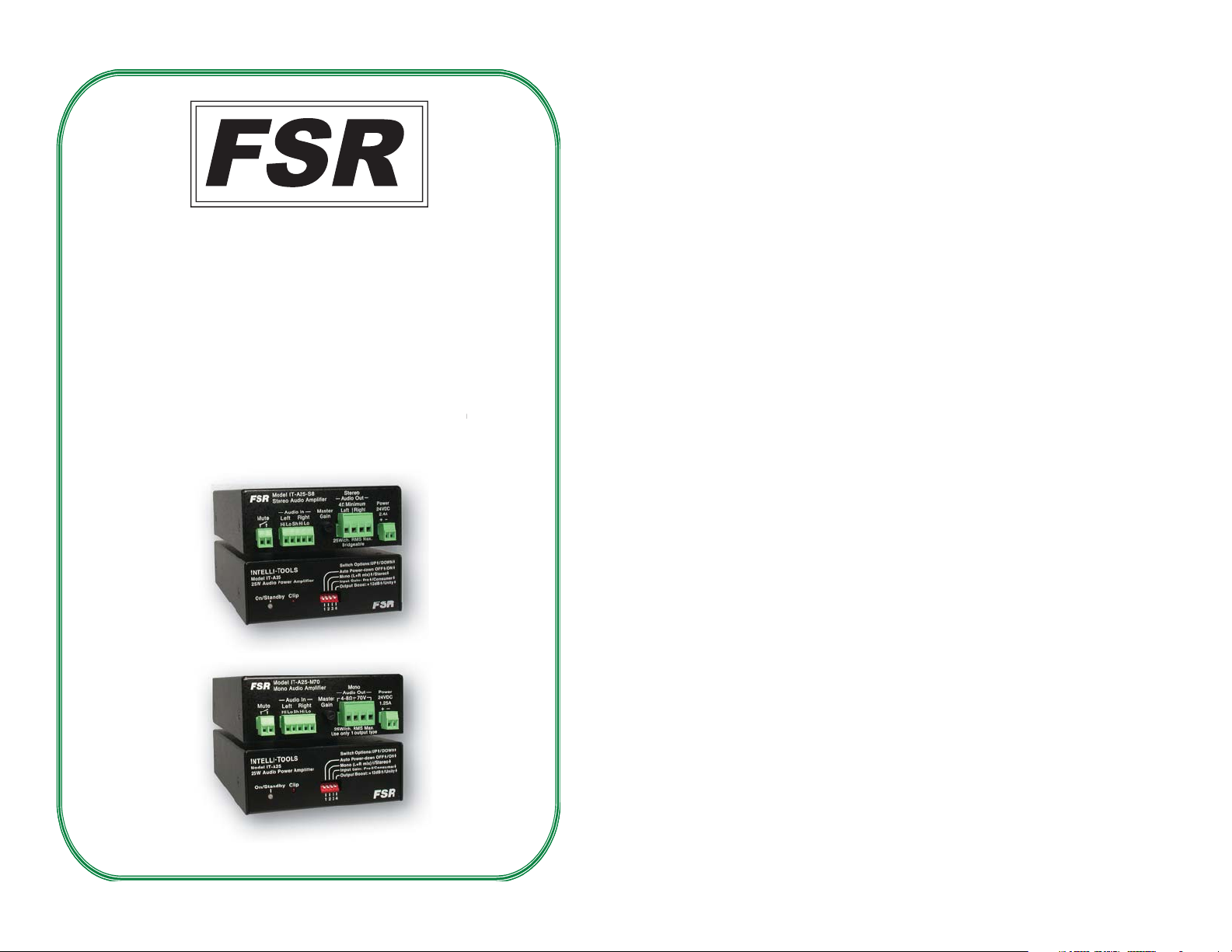
(COVERS MODELS IT-A25-M70 AND IT-A25-S8)
INSTALLATION AND OPERATING GUIDE
T ALLA TION AND OPERA TING
43949
LIT1336 D5
Page 2

PROPRIETARY INFORMATION
All information in this manual is proprietary to and the
property of FSR inc. This publication is protected by the Federal
Copyright Law, with all rights reserved. No part of this document
may be reproduced, transcribed, or transmitted, in any form or by
any means, without prior explicit written permission from FSR
Inc.
Operators Safety Summary
The general safety information in this summary is for operating
personnel.
Read Instructions Read and understand all safety and operating
instructions before using this equipment. Keep the instructions
handy.
Do Not Remove Covers or Panels There are no user-serviceable
parts within the unit. Removal of the top cover will expose
dangerous voltages. To avoid personal injury, do not remove the
top cover. Do not operate the unit without the cover installed.
Power Source This product is intended to operate from the
specifi ed wall plug-in transformer. Do not use any other power
source.
Use the Proper Power Cord Use only the power cord and
connector specifi ed for your product. Use only a power cord that is
in good condition. Refer cord and connector changes to qualifi ed
service personnel.
Do Not Operate in Explosive Atmospheres To avoid explosion,
do not operate this product in an explosive atmosphere.
2
Page 3

INTRODUCTION
The IT-A25 Series Amplifi ers are the latest addition to FSR’s
Intellitools family. They are designed to deliver great performance
and versatility at an affordable price. Perfect for small venue audio
power applications.
Both models support Pro and consumer audio input levels; The ITA25-M70 Mono Amp provides either a 4-8 ohm speaker output or
a 70 V line output at 25W RMS. The IT-A25 Stereo Amp delivers
a 25W output at 8 ohms and can be bridged to drive a 4 ohm load
at 50 watts.
FEATURES
• Signal Sense trigger for sleep & wake up
• Music and alarm muting capability
• Optional mounts available
• External Power Supply included
• Clean full-range power
APPLICATIONS
• Boardrooms • Houses of Worship• Control Rooms
• Classrooms• Staging and Rental •Libraries
ACCESSORIES
• RK-1 Rack mounting kit
• RK-2 Rack mounting shelf
3
Page 4

INST ALLA TION AND OPERA TION
Mount the units as appropriate for the particular installation.
There are #6-32` tapped holes on the top and bottom of the IT-A25
series housings for mounting. Use #6-32 screws that protrude through
no longer than 1/2". There are also rack kits available from FSR for
mounting in a standard 19” rack mount. See “accessories” section for
FSR part numbers and ordering information.
FRONT PANEL LED STATUS INDICATION
On/Standby: Green indicates the
amplifi er is active.
ON OFF STANDBY
CLIP
Amber indicates the amplifi er is
powered, but in Standby mode
drawing minimal current.
When lit this led indicates the
amplifi er is approaching the onset of
clipping.
4
Page 5

REAR PANEL
Mute Switch Input:
Provide a dry contact or low leakage open collector closure to
mute the amplifi er. No connection, or an open circuit provides
for normal operation. The IT-A25 amplifi er provides pop-free
transitions in and out of mute mode.
Audio Input:
NOTE: See Option DIP Switch table for proper settings and additional
information.
Connect a balanced or unbalanced audio source to this point.
Unbalanced signals should be connected between “Hi” and “Lo.”
For IT-A25-M70 only:
Connect mono sources to the LEFT audio input terminals
For IT-A25-S8 only:
Connect mono sources to the RIGHT or LEFT audio input terminals.
Master Gain control:
Provides a wide range volume control to adapt to audio source. CW
screwdriver or fi nger adjust to increase gain.
Audio Out:
For IT-A25-M70 only:
Provides a choice of either 4-8 ohm or 70 volt mono output for
fl exibility in interfacing to the room speakers. Connections should be
made to only one output type in a particular installation.
For IT-A25-S8 only:
Provides connection to 4-8 ohm stereo speakers. Outputs may be
bridged (connect + to + and connect - to - When bridging, be sure to
set front panel switch 2 to “mono” mode) to double the output power.
Use 4 ohm speaker, or parallel combination of 8 ohm speaker to
achieve full power when bridging outputs.
Power Input:
Connect to supplied 24 volt external power supply.
5
Page 6

OPTION DIP SWITCHES
Down=ON=Auto Power-down function
enabled,
AUTO POWER-DOWN
SWITCH 1
MONO/STEREO
SWITCH 2
UP=OFF=Auto Power-down function
disabled. This switch is used to override
the Auto Power-down feature of the
amplifi er and unconditionally force the
amplifi er to the on state.
Down=Stereo, Up=Mono. When in Mono
mode, the Left and Right audio inputs are
actively summed together and fed to both
the Left and Right output channels.
When in stereo mode, Left and Right
inputs are independent.
NOTE: The IT-A25-M70 mono version of
the product requires this switch to be set to
mono mode when using stereo sources.
When operating the IT-A25-S8 in bridged
output mode, this switch should also be set
to mono mode.
Up=Professional Audio input levels,
Down=Consumer Audio input levels.
INPUT GAIN
SWITCH 3
OUTPUT BOOST
SWITCH 4
When down, this switch provides an
additional 12 dB of input boost to
accommodate the lower signal levels of
consumer electronic equipment.
When up, this switch accommodates
the higher signal levels provided by
professional AV mixers.
Up= +12dB,
Down= Unity. When up, this switch
provides an additional 12 dB of gain to
provide additional fl exibility.
6
Page 7

AUDIO PINOUT
7
Page 8

DIMENSIONS
Depth is 6.75” on both models. Allow clearance for connectors and cables.
8
Page 9

TECHNICAL SPECIFICATIONS
AUDIO INPUT IT-A25-M70 IT-A25-S8
Number of Inputs 1, Stereo balanced
Connector 5 position pluggable screw terminal
Maximum Input Level 7 Vrms, +16.9dBV balanced/unbalanced
Input Impedance 20kȍ balanced/unbalanced
Input Signal Detection
Threshold
(for Auto Power Down)
AUDIO OUTPUT IT-A25-M70 IT-A25-S8
Connector 2 position pluggable screw
Power Output 25Wrms @ 70V
Signal Output Mono Stereo, 2 Mono, Bridgeable in
Load Impedance 4 to 8ȍ or 70V 4 to 8ȍ
THD+Noise 0.1% @ 10KHz, 10W 70V
Frequency Response 100Hz-20KHz, +0, -1dB;
Signal to Noise Ratio >97dB @ 70V,
terminal
25Wrms @ 4 to 8ȍ
Output
-3dB @ 50Hz
100Hz-20Khz, un-weighted
10mVrms, -40dBV
4 position pluggable screw
terminal
25Wrms x 2 @ 4 to 8ȍ
Mono mode
0.5% @ 1KHz, 25W 8ȍ
20Hz-20kHz, +0, -1dB
>90dB @ 25W 8ȍ,
20Hz-20KHz, Un-weighted
CONTROL ADJUSTMENTS IT-A25-M70 IT-A25-S8
x Auto Power Down
Control Switch
Remote Muting Input Dry contact closure required
Master Volume 9 9
FEATURES IT-A25-M70 IT-A25-S8
Auto Power Down 9 9
Clip Indicator 9 9
Output short circuit
protection
Bridgeable Output 9
Power up/down click and
Pop suppressor
x Stereo/Mono (L+R sum)
x Pro/Consumer (+12dB)
x Unity/+12dB Gain
9 9
9 9
9
Page 10

POWER REQUIREMENTS IT-A25-M70 IT-A25-S8
External power supply
Power input requirement 24V DC @ 1.2A 24V DC @ 2.4A
Power Consumption@ Full
Output
Standby Power
100-240VAC
d 28W d 58W
100-240VAC
d 1W
Idle Power
Model Dimensions (inches)
MECHANICAL
GENERAL IT-A25-M70 IT-A25-S8
LED Indicators
Operating Temperature 0° C to 40° C
Cooling Convection cooled
Enclosure Material Metal
Turn on time from Auto
Power Down (typical)
Time to enter Mute state
(typical)
Time to exit Mute state
(typical)
Amplifier Class D
IT-A25-M70
IT-A25-S8
d 3.5W
6.75 x 4.22 x 1.59
x Power On
x Standby
x Clip Indicator
25ms
<1ms
30ms
Shipping
weight
lbs.
2.5
1.5
10
Page 11

REGULATORY COMPLIANCE
The Power Adapter has been tested for compliance with: UL, CSA and CE.
WARRANTY POLICY
This product is warranted against failures due to defective parts or faulty workmanship for a period of
three years after delivery to the original owner. During this period, FSR will make any necessary repairs
or replace the unit without charge for parts or labor. Shipping charges to the factory or repair station must
be prepaid by the owner, return-shipping charges, via UPS / FedEx ground, will be paid by FSR.
This warranty applies only to the original owner and is not transferable. In addition, it does not apply
to repairs done by other than the FSR factory or Authorized Repair Stations.
This warranty shall be cancelable by FSR at its sole discretion if the unit has been
subjected to physical abuse or has been modifi ed in any way without written authorization from FSR.
FSR’s liability under this warranty is limited to repair or replacement of the defective unit.
FSR will not be responsible for incidental or consequential damages resulting from the use or misuse
of its products. Some states do not allow the exclusion of incidental or consequential damages, so the
above limitations may not apply to you. This warranty gives you specifi c legal rights, and you may also
have other rights which vary from state to state.
Warranty claims should be accompanied by a copy of the original purchase invoice
showing the purchase date (if a Warranty Registration Card was mailed in at the time of purchase, this
is not necessary). Before returning any equipment for repair, please read the important information
on service below.
SERVICE
Before returning any equipment for repair, please be sure that it is adequately packed and cushioned
against damage in shipment, and that it is insured. We suggest that you save the original packaging and
use it to ship the product for servicing. Also, please enclose a note giving your name, address, phone
number and a description of the problem.
NOTE: All equipment being returned for repair must have a Return Authorization (RMA)
Number. To get a RMA Number, please call:
FSR Service Department (973-785-4347).
Please display your RMA Number prominently on the front of all packages.
Contact Information:
FSR Inc.
244 Bergen Boulevard,
Woodland Park, NJ 07424
Tel: (973) 785-4347 · Fax: (973) 785-4207
E-Mail: sales@fsrinc.com · Web: http://www.fsrinc.com
11
 Loading...