

Page 1

HuddleVU Collaboration
System
INSTALLATION AND OPERATING GUIDE
43039 LIT1455
Page 2

COMPLIANCE AND SAFETY
PROPRIETARY INFORMATION
All information in this manual is proprietary to and the property of FSR Inc. This publication is protected
by the Federal Copyright Law, with all rights reserved. No part of this document may be reproduced, transcribed, or transmitted, in any form or by any means, without prior explicit written permission from FSR Inc.
OPERATOR’S SAFETY SUMMARY
The general safety information in this summary is for operating personnel.
Read Instructions. Read and understand all safety and operating instructions before using this equipment.
Keep the instructions handy.
Removal of the top cover may expose dangerous voltages. To avoid personal injury, disconnect all power
sources before removing the top cover. Do not operate the unit with the cover removed.
Power Source:
This product is intended to operate from the power source detailed in the specifi cation section of this manual.
Do not use any other power source or exceed voltage limits.
Grounding the Product:
This product is grounded through the grounding conductor of the power cord. To avoid electrical shock, plug
the power cord into a properly wired receptacle before connecting to the product input or output terminals.
Use the Proper Power Cord. Use only the power cord and connector specifi ed for your product. Use only a
power cord that is in good condition. Refer cord and connector changes to qualifi ed service personnel.
Huddle-VU
2
Page 3

TABLE OF CONTENTS
COMPLIANCE AND SAFETY .............................................................................................................2
PROPRIETARY INFORMATION .............................................................................................................................2
OPERATOR’S SAFETY SUMMARY .......................................................................................................................2
INTRODUCTION...................................................................................................................................5
FEATURES: ................................................................................................................................................................5
APPLICA TIONS: ........................................................................................................................................................5
HV-T3 TABLE BOX INSTALLATION .....................................................................................................................6
MOUNTING INFORMATION .............................................................................................................6
HV-T6 TABLE BOX INSTALLATION .....................................................................................................................7
HUDDLEVU BRACKET SET INSTALLATION .....................................................................................................8
HUDDLEVU BRACKET SET CABLING FOR A FIVE HV-T3 INSTALLATION ............................................ 13
HUDDLEVU BRACKET SET CABLING FOR AN HV-T6 INSTALLATION ....................................................13
MECHANICAL DIMENSIONS ..........................................................................................................14
HV-T3 TABLE BOX .................................................................................................................................................14
HV-T6 TABLE BOX .................................................................................................................................................15
DV-HSW-41 4X1 SWITCHER ................................................................................................................................. 16
HV-CTL CONTROL BOX ......................................................................................................................................16
DV-PC2HD ANALOG PC TO HDMI CONVERTER (OPTION) ..........................................................................17
IT-SACWP SWITCHED WALL PLATE (OPTION) ...............................................................................................18
OPERATION .........................................................................................................................................19
HV-1000 4-PERSON SYSTEM DIAGRAM ......................................................................................20
MULTI-PERSON SYSTEM DIAGRAM ...........................................................................................21
HV-CTL HUDDLEVU CONTROLLER ............................................................................................22
DV-HSW-41 HDMI SWITCHER ........................................................................................................23
DV-PC2HD ANALOG PC TO HDMI CONVERTER ......................................................................24
IT-SACWP SWITCHED WALL PLATE ............................................................................................25
RS-232 PROTOCOL ............................................................................................................................26
HUDDLEVU BEHAVIOR .......................................................................................................................................26
LOCKING/UNLOCKING SWITCH INPUTS .......................................................................................................26
POWERING THE MONITOR ON/OFF SERIALLY ..............................................................................................27
3
Huddle-VU
Page 4

HUDDLE VU SERIAL COMMANDS ................................................................................................................................28
HV-CTL REQUEST LIST QUICK REFERENCE ..........................................................................................................28
REQUEST/RESPONSE FORMAT ..................................................................................................................................29
COMMAND REQUEST SYNTAX: ................................................................................................................................29
COMMAND REQUEST COMMENT FIELDS ..............................................................................................................29
ACKNOWLEDGING RECEIPT OF COMMANDS .......................................................................................................30
ERROR RESPONSE .........................................................................................................................................................30
CONNECTION REQUEST ............................................................................................................................................. 31
HELP REQUEST ..............................................................................................................................................................32
LOCK REQUEST .............................................................................................................................................................34
POWER REQUEST ..........................................................................................................................................................35
RELAY REQUEST ...........................................................................................................................................................36
RESPONSE REQUEST ....................................................................................................................................................37
SERIAL BIT RATE REQUEST.......................................................................................................................................38
STATUS REQUEST .........................................................................................................................................................39
UNLOCK REQUEST .......................................................................................................................................................40
VERSION REQUEST ......................................................................................................................................................41
VERBOSE REQUEST .....................................................................................................................................................42
DV-HSW-41 PINOUTS AND CABLING ......................................................................................................43
DB-9 CONNECTION ............................................................................................................................................................43
SPECIFICATIONS ..........................................................................................................................................45
HV-CTL .................................................................................................................................................................................45
DV-HSW-41 ............................................................................................................................................................................45
DV-PC2HD ............................................................................................................................................................................45
IT-SACWP..............................................................................................................................................................................46
WARRANTY AND RETURN INFO ..............................................................................................................47
WARRANTY POLICY .........................................................................................................................................................47
SERVICE AND RETURN AUTHORIZATION ..................................................................................................................47
CONTACT INFORMATION ................................................................................................................................................47
Huddle-VU
4
Page 5

INTRODUCTION
The HuddleVU system allows for multiple users to share and view their laptops, tablets, and smart phones
screens on a main display. Unlike conventional presentation systems, anyone participating can lead the
presentation at any given time at the push of a button. LED’s indicate which user is currently live and when
the system is busy.
HuddleVU creates the ideal environment for people to view and share ideas. The systems include all the
necessary video switching equipment, control hardware, display po wer control and color-coded captive HDMI
cables. It is a very simple yet effective system to quickly install and use.
There are two model styles available:
The HV-1000 single table box system employs a single FSR HV-T6 table box that allows 1 to
4 users to plug in and power their laptops or other input devices and simply push a button to
display their desktop information on the main display. Any user can switch to their own laptops,
tablets, and smartphones at any time simply by pushing their button on the T6 housing.
The individual HV systems accommodate from 3 to 7 users depending on the model. Each user
has their own FSR HV-T3 table box to plug into. Each table box contains a pullout HDMI cable
and an AC outlet. A single push of a button on each T3 is all that is needed to display the laptop
or iPad’s desktop information onto the main display. An HV-CTL Controller and up to two DVHSW-41 HDMI Switchers are included on all systems. The HV-CTL has a power switch, two
AC outlets to power the DV-HSW-41 HDMI Switchers and an additional AC outlet to power the
main display. The HV-CTL is the main termination point for the system components. When
four or less inputs are used the HV-CTL switching can be serially controlled by an external
control system.
FEATU R ES:
•
Single button press user selection
• No software or programming required
• Simple installation
• Create attractive workspaces
• Hardware and cables included
• Conversion kits available for VGA and audio input
• Systems with four or less inputs can be controlled by an external control system
APPLICATIONS:
•
Classrooms
• Libraries
• Conference Rooms
• Educational Facilities
• Corporate Teleconference Rooms
• Learning Centers
• Training Rooms
5
Huddle-VU
Page 6
MOUNTING INFORMATION
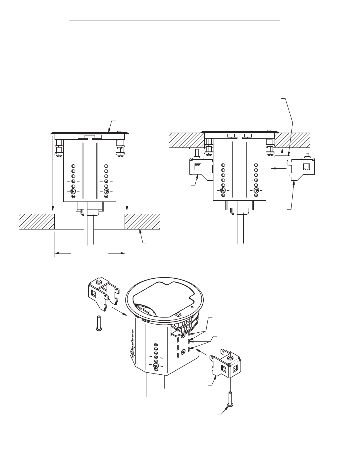
HV-T3 TABLE BOX INSTALLATION
HV-T3 INSTALLATION INSTRUCTIONS
1.
DRILL 3.50" DIAMETER HOLE IN TABLE TOP.
2.
INSERT HV-T3 ASSEMBLY AND ORIENT AS REQUIRED.
3.
INSTALL MOUNTING CLAMPS TO ASSEMBLY AND SECURE TO TABLE BY
SCREWING MOUNTING SCREWS TO UNDERSIDE OF TABLE.
4.
MAKE ELECTRICAL CONNECTIONS AS REQUIRED. ENSURE HDMI
CONNECTOR CAN BE PULLED OUT 3'-0".
HV-T3 ASSEMBLY
MOUNTING
CLAMP AND
MOUNTING
SCREW
INSTALLED
CUSTOMER TO PROVIDE
KO SLUG/PENNY/OTHER
HARD FLAT PIECE FOR
SCREW END, WITH SOFT
TABLE WOOD
MOUNTING
CLAMP AND
MOUNTING
SCREW
(SEE BELOW)
3.50" DIAMETER
NOTE: TABLE BOXES ARE AUTOMATICALLY
GROUNDED WHEN THAY ARE PLUGGED INTO AN
AC OUTLET. IF THE UNITS ARE NOT PLUGGED
INTO AN AC OUTLET THEY MUST BE MANUALLY
GROUNDED.
TABLE
SLOTS USED FOR 5/8" TO
1-1/8" THICK TABLE TOPS
SLOTS USED FOR 1-1/8" TO
1-9/16" THICK TABLE TOPS
(2) MOUNTING
CLAMP
(2) MOUNTING
SCREW
Huddle-VU
6
Page 7
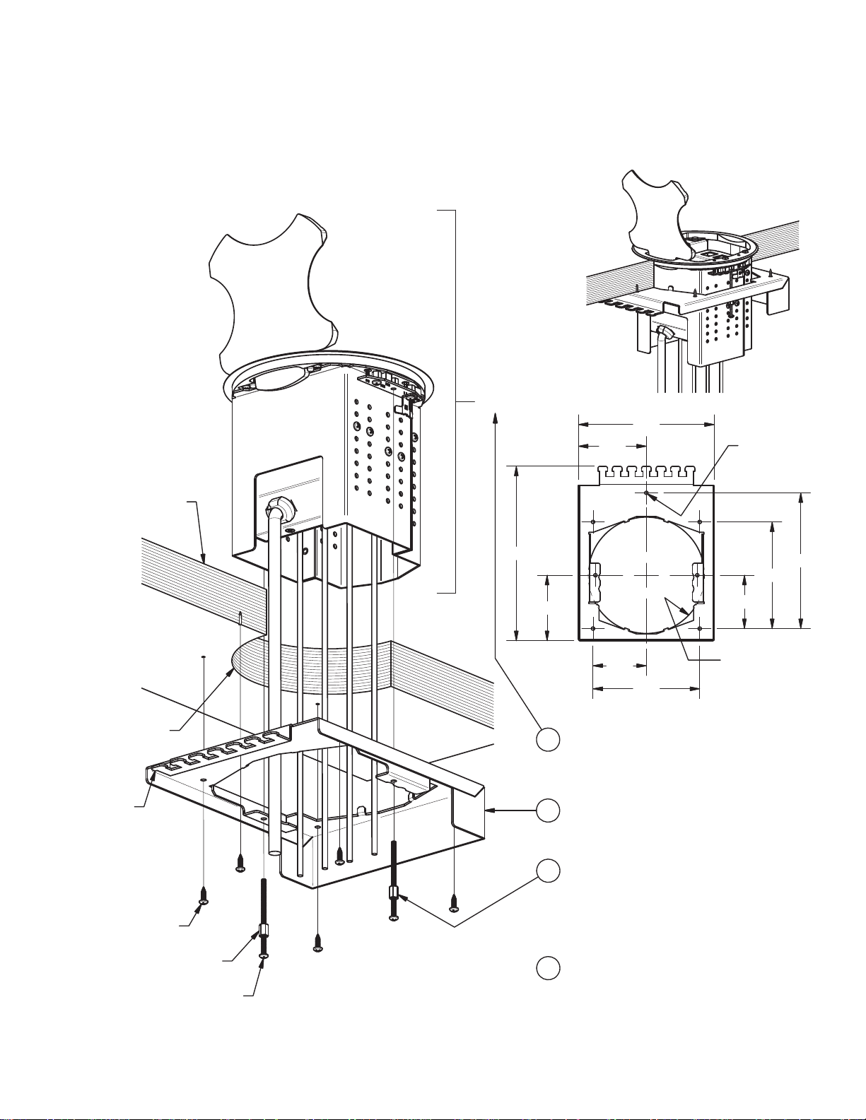
HV-T6 TABLE BO X INSTALLATION
HV-T6 INSTALLATION
INSTRUCTIONS
3/4" MIN. - 2-1/4" MAX.
TABLE THICKNESS
PRE-CUT 6.00" DIA.
HOLE IN TABLE
(7) CABLE
TIE TAB
(5) #6 / #8 x 1/2"
WOOD SCREW
(2) 3/8"-LONG
CLAMP NUTS
(2) #6-32 x 2.00" or 2-1/2" or 3" LONG
PAN HEAD SCREW
HV-T6 SUB-ASS'Y
9.00
NOTE: TABLE BOXES ARE AUTOMATICALLY
GROUNDED WHEN THAY ARE PLUGGED INTO AN
AC OUTLET. IF THE UNITS ARE NOT PLUGGED
INTO AN AC OUTLET THEY MUST BE MANUALLY
GROUNDED.
7
ASSEMBLED VIEW
7.00
3.50
3.38
2.75
5.50
UNDERSIDE VIEW OF SHROUD
2
INSTALL DESIRED BRACKETS INTO THE
'HV-T6' SUB-ASS'Y. DROP THE SUB-ASS'Y
INTO THE HOLE IN THE TABLE
(COVER ORIENTATION IS PRE-SET
BY THE SHROUD INSTALLATION).
1
INSTALL CLAMP SHROUD TO UNDERSIDE
OF TABLE HOLE WITH (5) WOOD SCREWS
AS SHOWN. ORIENT PER DESIRED
COVER SWING DIRECTION.
3
PASS THE DESIRED-LENGTH (2) LONG
SCREWS THRU THE SH ROUD AND THREAD
INTO THE SUB-ASS'Y. TURN THE 3/8"-LONG
CLAMP NUTS UP SNUG AGAINST THE
SHROUD BASEPLATE TO PULL THE
SUB-ASS'Y DOWN COMPL
PLACE IN THE PRE-CUT 6.00" DIA. HOLE.
MAKE ELECTRICAL CONNECTIONS AS
4
REQUIRED AND TIE-WRAP CABLES TO
TIE-TABS. ENSURE HDMI CONNECTORS IN
THE SUB-ASS'Y CAN BE PULLED OUT 3'-0"
PRIOR TO SECURING CABLES TO TIE TABS.
6.00" DIA. THRU
HOLE IN TABLE
ETELY INTO
(5) #6 / #8
MOUNTING
SCREW
HOLES
7.00
5.50
2.75
Huddle-VU
Page 8
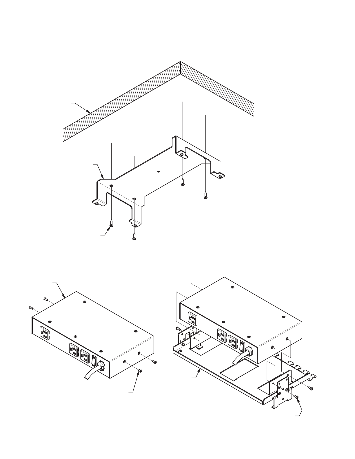
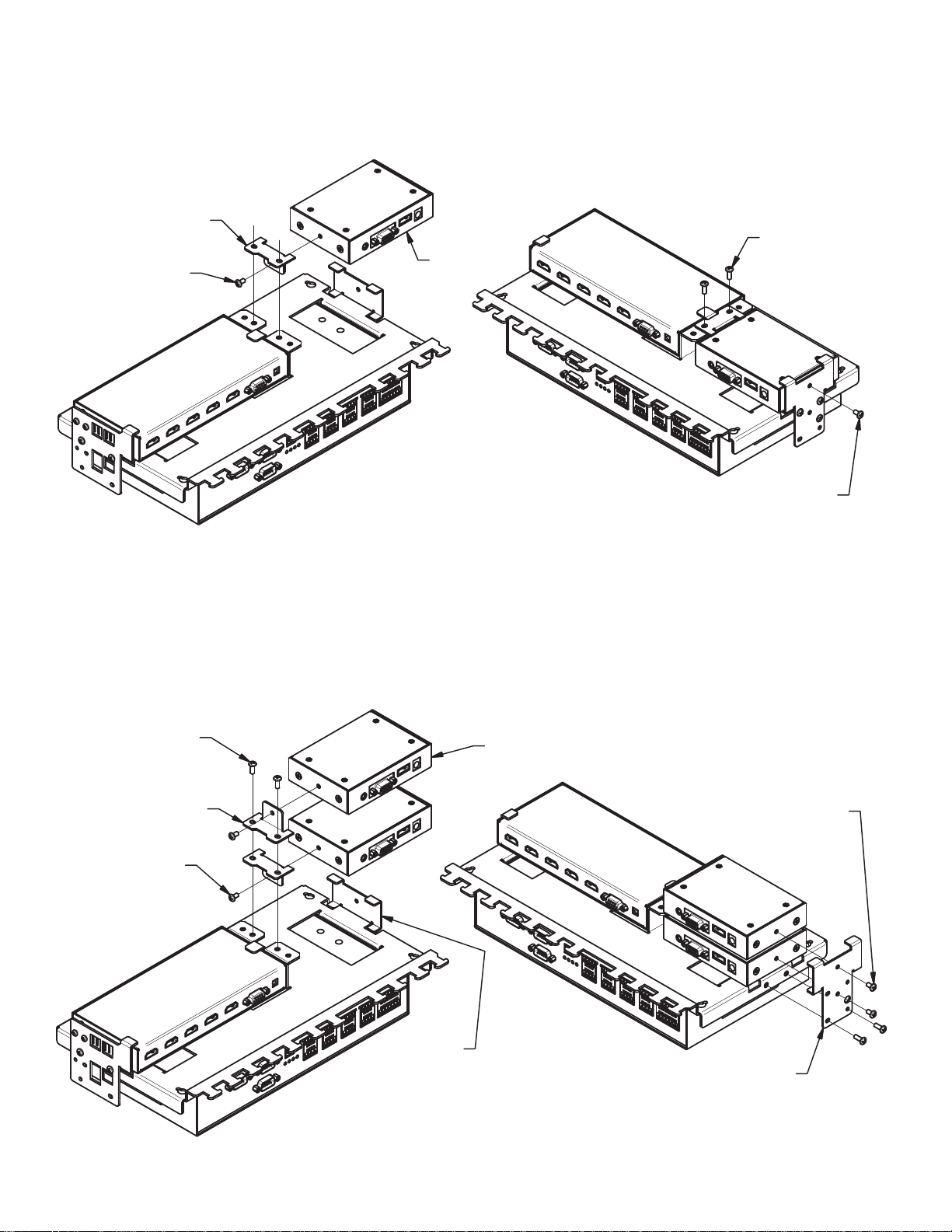
HUDDLEVU BRACKET SET INSTALLATION
1.
LOOSEN BASE PLATE SCREWS AND SEPARATE
BASE PLATE FROM TABLE BRACKET. DETERMINE
EQUIPMENT LOCATION AND MOUNT TABLE
BRACKET TO UNDERSIDE OF TABLE WITH
SUPPLIED #8 WOOD SCREWS OR CUSTOMER
SUPPLIED #8 COUNTER-SUNK HARDWARE.
TABLE
TABLE BRACKET
(4) #8 COUNTER-SUNK HARDWARE
2.
REMOVE AND DISCARD EXISTING SCREWS FROM
HV-CTL UNIT.
HV-CTL
REMOVE AND DISCARD
3.
INSTALL HV-CTL TO BASE PLATE WITH SUPPLIED
#6 HARDWARE.
BASE PLATE
Huddle-VU
(4) #6-32 x 3/8" LONG
8
Page 9
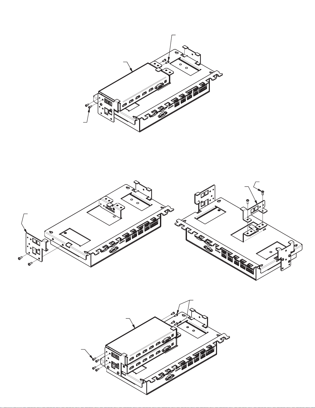
4A.
INSTALLING ONE DV-HSW-41 UNIT:
a.
INSTALL DV-HSW-41 TO BASE PLATE WITH SUPPLIED
M3 HARDWARE.
(4) M3 x 8mm LONG
PAN-HEAD SCREW
4B.
INSTALLING TWO DV-HSW-41 UNITS:
OMIT THIS SCREW FOR
EASE OF FIELD SERVICE
DV-HSW-41
a.
REMOVE DV-HSW-41 SIDE BRACKET AND REINSTALL
TO NEW POSITION ONTO BASE PLATE.
SIDE BRACKET
c.
INSTALL DV-HSW-41 TO BASE PLATE WITH SUPPLIED
M3 HARDWARE.
(2) DV-HSW-41
b.
INSTALL DV-HSW-41 MOUNTING/SUPPORT BRACKET
TO BASE PLATE WITH SUPPLIED #6 HARDWARE.
MOUNTING/
SUPPORT
BRACKET
OMIT THESE SCREWS FOR
EASE OF FIELD SERVICE
(2) #6-32 x 3/8" LONG
PAN-HEAD SCREW
(8) M3 x 8mm LONG
PAN-HEAD SCREW
9
Huddle-VU
Page 10
5A.
INSTALLING ONE DV-PC2HD UNIT:
a.
INSTALL MOUNTING BRACKET TO DV-PC2HD WITH #6
HARDWARE (MOUNTING BRACKET AND #6 HARDWARE
SUPPLIED WITH DV-PC2HD).
MOUNTING BRACKET
SUPPLIED WITH DV-PC2HD
#6-32 x 1/4" LONG
PAN-HEAD SCREW
SUPPLIED WITH
DV-PC2HD
DV-PC2HD
b.
INSTALL DV-PC2HD WITH ATTACHED MOUNTING
BRACKET TO BASE PLATE WITH SUPPLIED #6 HARDWARE
AND #6 HARDWARE SUPPLIED WITH DV-PC2HD.
(2) #6-32 x 3/8" LONG
PAN-HEAD SCREW
#6-32 x 1/4" LONG
PAN-HEAD SCREW
SUPPLIED WITH
DV-PC2HD
5B.
INSTALLING TWO DV-PC2HD UNITS:
a.
REMOVE DV-PC2HD SIDE BRACKET. INSTALL MOUNTING
BRACKET TO DV-PC2HD WITH #6 HARDWARE (MOUNTING
BRACKET AND #6 HARDWARE SUPPLIED WITH DV-PC2HD).
INSTALL DV-PC2HD WITH ATTACHED MOUNTING BRACKET
TO BASE PLATE WITH SUPPLIED #6 HARDWARE.
(2) #6-32 x 3/8" LONG
PAN-HEAD SCREW
(2) MOUNTING BRACKET
SUPPLIED WITH DV-PC2HD
(2) #6-32 x 1/4" LONG
PAN-HEAD SCREW
SUPPLIED WITH
DV-PC2HD
b.
REINSTALL SIDE BRACKET TO BASE PLATE AND
SECURE DV-PC2HD WITH #6 HARDWARE SUPPLIED
WITH DV-PC2HD.
(2) DV-PC2HD
(2) #6-32 x 1/4" LONG
PAN-HEAD SCREW
SUPPLIED WITH
DV-PC2HD
Huddle-VU
REMOVE
SIDE BRACKET
10
REINSTALL SIDE BRACKET
Page 11
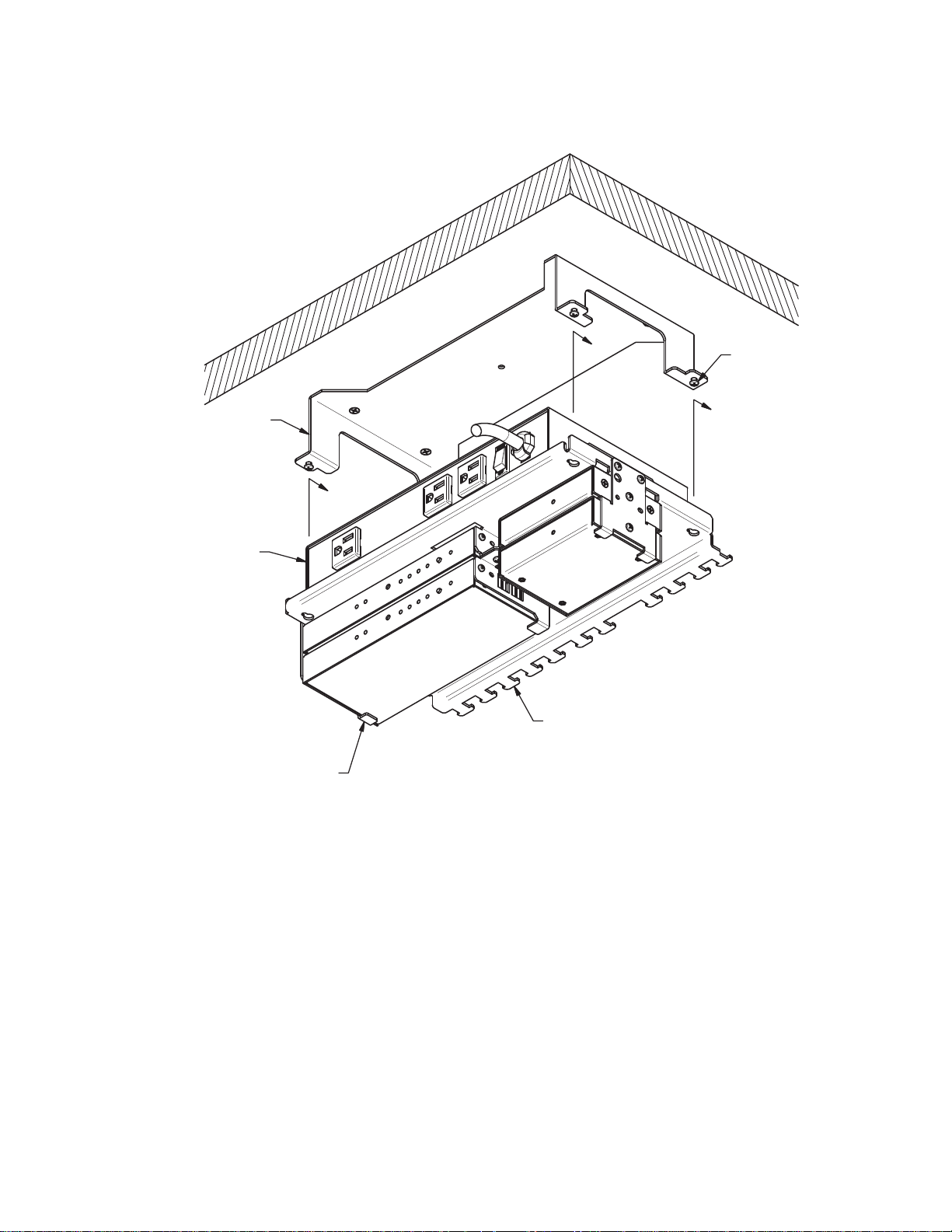
6.
REINSTALL BASE PLATE ASSEMBLY TO TABLE BRACKET AND
MAKE ELECTRICAL CONNECTIONS AS REQUIRED. TIE-WRAP
CABLES TO TIE-TABS AS REQUIRED.
INSTALLED
TABLE BRACKET
TIGHTEN SCREWS
AFTER REINSTALLING
BASE PLATE ASSEMBLY
TO TABLE BRACKET
HV-CTL UNIT CAN BE
REMOVED WITHOUT
REMOVAL OF BASE
PLATE ASSEMBLY
BASE PLATE ASSEMBLY
(11) TIE-TAB
11
Huddle-VU
Page 12

Huddle-VU
12
Page 13
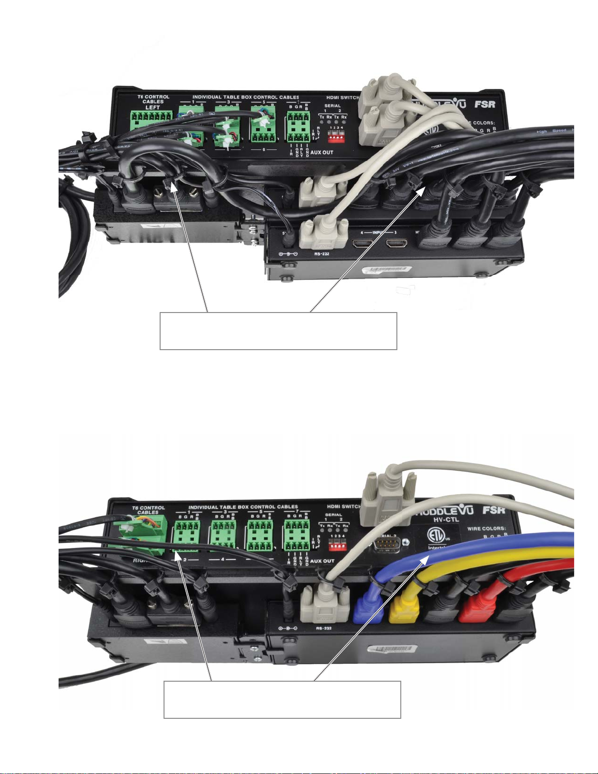
HUDDLEVU BRACKET SET CABLING FOR A FIVE HV-T3 INSTALLATION
USE THE TABS PROVIDED TO SECURE THE
CABLES USING TIE WRAPS THROUGHOUT
HUDDLEVU BRACKET SET CABLING FOR AN HV-T6 INSTALLATION
USE THE TABS PROVIDED TO SECURE THE
CABLES USING TIE WRAPS THROUGHOUT
13
Huddle-VU
Page 14
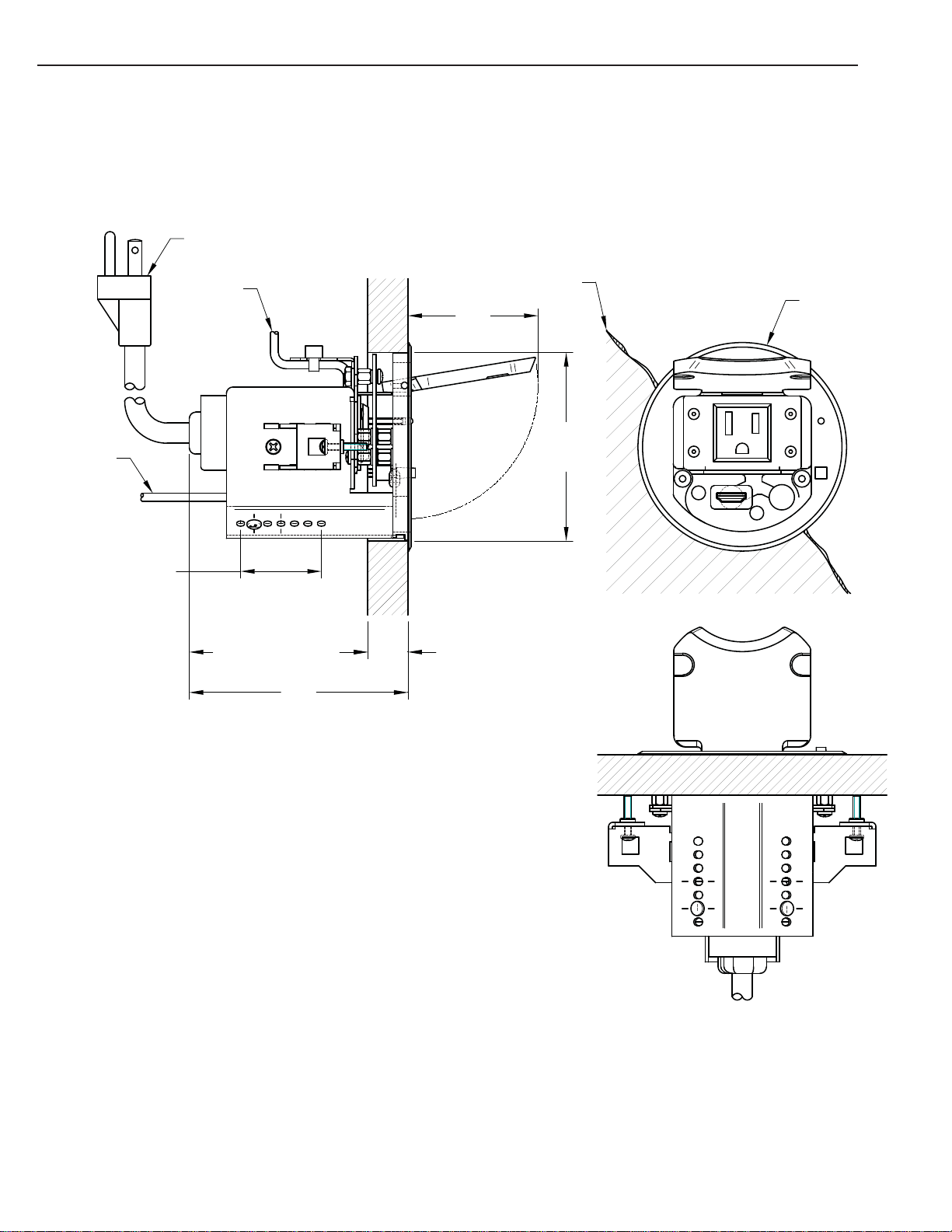
HV-T3 TABLE BOX
POWER CORD
MECHANICAL DIMENSIONS
HDMI CABLE
1.50 ADJUST MENT RANGE
CONTROL
CABLE
2.50 MIN - 3.435 MAX
BENEATH BOTTOM
SURFACE OF TABLE
4.06
TABLE
2.42
3.50 DIA
IN TABLE
.625 MIN - 1.562 MAX
TABLE THICKNESS
HOLE
3.88 DIA BEZEL
CURRENT
DRAW
12A, MAX.
Huddle-VU
14
Page 15
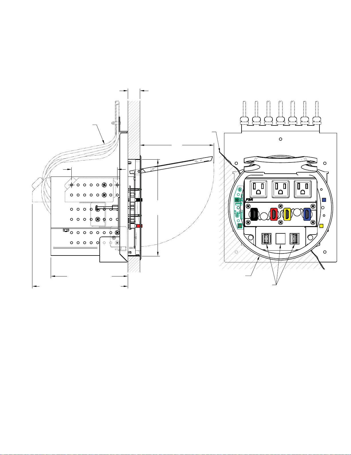
HV-T6 TABLE BOX
CABLE MUST BE LOOPED IF USED
WITH CABLE PULL BRACKET (T6-LB-CP)
TO ACCOMODATE PULLOUT LENGTH
2.84 ADJUSTMENT
RANGE
.75 MIN - 2.25 MAX
TABLE THICKNESS
4.59
TABLE
4.78 BENEATH BOTTOM
5.94 BENEATH BOTTOM SURFACE OF TABLE
WITH AC BRACKET AT LOWEST LEVEL
SURFACE OF TABLE
6.00 DIA
HOLE IN
TABLE
6.50 DIA BEZEL
BLANKS PROVIDED, KEYSTONE
SNAP-IN SOLD SEPARATELY
TOTAL CURRENT DRAW:
12A, MAX.
T6
15
Huddle-VU
Page 16

DV-HSW-41 4X1 SWITCHER
HV-CTL CONTROL BOX
FSR
T6 CONTROL
CABLES
LEFT
RIGHT
HDMI SWITCHER POWER
SWITCHED AC POWER - TOTAL CURRENT DRAW, ALL RECEPTACLES: 12A, MAX.
FRONT VIEW
10.64
INDIVIDUAL TABLE BOX CONTROL CABLES
1
B
RGB
B
2
35
B
RGB
B
4
7
B
RGB
6
B
RGB
B
B
G
G
R
I
N
N
L
R
D
D
Y
BACK VIEW
HDMI SWITCHER CONTROL
SERIAL
1
2
Tx Rx Tx Rx
1234
R
I
L
R
Y
1234
AUX OUT
MONITOR POWER
SERIAL 1
SERIAL 2
RESET
OFF
HV-CTL
120VAC 50/60 Hz
15 Amp Max.
WIRE COLORS:
BGR
BLUE
GREEN
RED
BLK & BRN
HV-CTL
FSR
6.06
6.48
2.00
B
B
Huddle-VU
16
Page 17

G
DV-PC2HD ANALOG PC TO HDMI
CONVERTER (OPTION)
POWER INDICATOR LED
2.98
POWER
FSR
WOODLAND PARK, NJ 07424
TEL: (973) 785-4347
www.fsrinc.com
POWER
OUTPUT ANALOG PC INPUT
HDMI VIDEO AUDIO
5VDC
4.15
POWER
DV-PC2HD
HDMI CONVERTOR
Model
ANALOG PC
TO
3.21
(2) SUPPLIED MOUNTING
BRACKET SCREW
1.03
BRACKETS CAN BE POSITIONED FOR
SURFACE OR UNDERSIDE MOUNTING
(2) SUPPLIED
MOUNTIN
BRACKET
17
Huddle-VU
Page 18

IT-SACWP SWITCHED WALL PLATE (OPTION)
SWITCHED AC
12A MAX.
TO AC
POWER
4.09
12V RELAY
-
+
ON
IT-SACWP
FSR
1.70 .15 1.43
2.72
2.41
1.57
Huddle-VU
18
Page 19

OPERATION
Power up the system via the power switch located on the AC side of the HV-CTL Control Unit. The Green
LEDs on the Table Boxes (referred to as "TB" from this point on) will fl ash for approximately 3 seconds and
then turn off. The system is now in the IDLE state and is ready to accept switch inputs/presses from the table
boxes. Note that the monitor and HDMI switchers are not yet turned on and no switch inputs are honored
while the LEDs are fl ashing.
From the IDLE state, press any one of the available switches on any of the TB's to activate the system. The
monitor and HDMI switcher(s) will be immediately powered ON and all TB Green LEDs will fl ash for a
short time to indicate the system is powering up. Upon release of the selected switch, the selected switch’s
corresponding Green LED will fl ash at a fast rate for a short duration before turning steady green (to indicate
that particular selection was recognized). All other TB LEDs remain Red and the HDMI source from that
input is selected and is routed to the monitor. While the green LEDs of the selected input switch are fl ashing,
no other switch selections are honored. The unit is now in the ON state and is ready to accept additional
switch presses allowing the users to switch their source's program material to the monitor. (There is no
unconnected state for the HDMI switchers.)
Subsequent switch presses on any of the TB switches for less than 3 seconds will select that TB's source and
display it on the monitor. The Green LED will fl ash at a fast rate for a short duration to indicate the selection
was recognized, all other TB LEDs will go Red upon release of the switch. While the green LEDs of the
selected input switch are fl ashing, no other switch selections are honored. The unit remains in the ON state.
To return the system to the IDLE state: Press and hold any switch for a duration of greater than 3 seconds.
The monitor and HDMI switcher(s) will be switched OFF at the 3 second mark, all TB Red LEDs will fl ash
for a short time (approximately 3 seconds) and then all TB LEDs will be turned OFF indicating a return to the
IDLE state.
19
Huddle-VU
Page 20

T6 CONTROL
CABLES
LEFT
RIGHT
INDIVIDUAL TABLE BOX CONTROL CABLES
1
35
B
B
RGB
B
2
B
RGB
RGB
B
B
4
6
7
RGB
G
R
I
N
L
R
D
Y
HDMI SWITCHER CONTROL
B
SERIAL
B
1
Tx Rx Tx Rx
1234
R
I
L
R
Y
1234
G
N
AUX OUT
D
HV-1000 4-Person System Diagram
2
Optional
IT-SACWP
SERIAL 1
SERIAL 2
HV-CTL
WIRE COLORS:
BGR
BLUE
GREEN
RED
BLK & BRN
FSR
B
B
Optional IT-SACWP-12
Switched AC Wallplate
SWITCHED AC
12A MAX.
12V RELAY
-
+
ON
IT-SACWP
FSR
Connects To Relay Inputs
On HV-CTL Controller
AC Power Can
Also Connect To
HV-CTL Controller
Display
HDMI Cable
To Display
(Provided)
9' AC cord with Edison Plug
attached to T6 Table box.
(Supplied)
Black
Red
Yellow
Blue
Blue
Yellow
Red
Captive Screw Terminal
Pin Numbering
HV-1000 Huddle -VU 4 Person
Black
System Includes:
1 – HV-T6-BLK, 4-HDMI Input Table Box
1 – HV-CTL, Huddle-VU Control Unit
1-DV-HSW-41, HDMI Switcher
4-HDMI 6' Cables (Premounted in HV-T6-BLK)
1-HDMI 10' Cable
1 – Null Modem 6' Serial Cable
*Switches are Normally Open (N.O.) contact closure to ground.
LED drive voltage is 10.5 Vdc, nominal 6 mA, current limited at LED
Huddle-VU
20
Page 21

Multi-Person System Diagram
Multi-Person Collaboration Systems
Multi-Person HuddleVU System Includes:
1-HV-CTL HuddleVU Control Unit
1-Null Modem 6’ Serial Cable
1-HDMI 10’ Cable (To Display)
1-DV-HSW-41 HDMI Switcher (Up to 4 Users)
(2nd DV-HSW-41 & Null Modem 6’ Serial Cable included with
5+ User Packages)
1-HV-T3-BLK Table Box (Per User)
1-6’ HDMI & Control Cables (Included in HV-T3-BLK)
SingleUser T3Boxes
(mounted in table)
Equipment Mounted
Under Table
User #7
HV-CTL
Controller
RS-232 Control Cable(s)
To Switcher(s)(Provided)
9' AC cord with Edison Plug attached
to each T3 Table box. (Provided)
User #6
Optional
IT-SACWP
User #4
P
o
we
To
C
o
P
o
wer
To
Co
Huddle -VU
Multi-Person Systems:
User #1
HV-300 Huddle-VU (3 Users)
HV-400 Huddle-VU (4 Users)
User #2
HV-500 Huddle-VU (5 Users)
HV-600 Huddle-VU (6 Users)
HV-700 Huddle-VU (7 Users)
User #3
HDMI Cables Pass-Thru
HV-T3 Table Box To Switcher
(Provided With Table Box)
Display
Control Cables
(Provided With Table Box)
FSR
r C
on
n
e
c
t
s
n
t
r
o
l
Box
Co
n
nects
n
tro
l
Bo
x
User #7
User #6
67
5
HDMI Switcher #1
1234
HDMI Switcher #2
DV-HSW-41
DV-HSW-41
SingleUser T3Box
(mounted in table)
User #5
Optional IT-SACWP-12
Switched AC Wallplate
FSR
Connects To Relay AUX OUT
On HV-CTL Controller
AC Power Can
Also Connect To
HV-CTL Controller
1 2 3 4
Captive Screw
Terminal Pin
Numbering
SWITCHED AC
12A MAX.
12V RELAY
-
+
ON
IT-SACWP
HDMI Cable
To Display
(Provided)
HV-T3 Tab le Box Cable Harne ss De tail
1 - Blue Switch - (N. O .)
2 - Green LED - Green +
3 - Red LED - Red +
4 - Black & Brown Ground
* Switches are Normally Open (N.O.) contact
closure to ground. LED drive voltage is 10.5
VD C , Nominal 6 mA, current limited @ LED
FunctionPin # / Wire Color
21
Huddle-VU
Page 22

HV-CTL HUDDLEVU CONTROLLER
HDMI switcher power outlet
HDMI switcher power outlet
Monitor power outlet
Power switch and circuit breaker
Power cord
T6 Left control ports
T6 Right control ports
T3 control ports #1 with status indicator
T3 control ports #2 with status indicator
T3 control ports #3 with status indicator
21
3 4
5
T3 control ports #4 with status indicator
T3 control ports #5 with status indicator
T3 control ports #6 with status indicator
T3 control ports #7 with status indicator
12Vdc relay drive output, IR output (for
future use) and status indicator
RS-232 data indicators
DIP switch (for future use)
HDMI switcher RS-232 port, Male DB-9
HDMI switcher RS-232 port, Male DB-9
Huddle-VU
6
7 9
15
16
8
10 12 14
11 13 15 17
22
18
19
Page 23

DV-HSW-41 HDMI SWITCHER
DV HSW 41 HDMI SWITCHE
4
5
Serial transmit and receive LEDs
IR sensor
HDMI input status LEDs
HDMI input selector switch
Power LED
5VDC power input
1
2
3
RS-232 port
HDMI input 4
HDMI input 3
HDMI output
HDMI input 2
HDMI input 1
7
6
23
9
10
11
12
Huddle-VU
8
Page 24

DV-PC2HD ANALOG PC TO HDMI
OGPCTO
DV-PC2HD ANAL
HDM
CONVERTER
ERTER
1
5
4
3
2
Power LED
5VDC power input
HD-15 VGA input
Stereo 3.5mm audio input
HDMI output
The DV-PC2HD converts a variety of VGA signals and stereo audio to HDMI. The signal resolution at the
HDMI output is dependent on the VGA input resolution as shown in the table below. The unit is easy to
install and operate and does not require any adjustments.
Video Resolutions supported by the DV-PC2HD @ 60 Hz
1920 x 1080 1 6 80 x 1050 1 600 x 1200
1 600 x 1024 1 600 x 900 1 440 x 900
13 60 x 1024 1366 x 768 1360 x 7 68
1280 x 1024 1280 x 960 1280 x 900
1280 x 800 1280 x 768 1280 x 720
1152 x 864 102 4 x 768 800 x 600
640 x 480
Huddle-VU
NOTE: Audio will not pass
through without a video
signal.
24
TOTAL CURRENT DRAW:
CURRENT
12A, MAX.
T6
12A, MAX.
DRAW
Page 25

IT-SACWP SWITCHED WALL PLATE
The IT-SACWP wall plate provides convenient, remotely switched AC to power projectors, displays and
other AC powered devices via a low voltage hard wired control input. A great accessory to use with the
HuddleVU system.
The single gang, Decora style, 12 amp rated, switched AC outlet wires directly to a 15 amp branch circuit via
the input harness at the back of the unit. Connections to the branch circuit are made using the included wire
nuts.
The switching technology is relay based for reliable operation and minimal heat dissipation. Control
is accomplished via the fi xed 2 position screw terminal connector. A green LED is provided for visual
indication of the relay relay state. The unit requires a 12VDC @ 88mA input to operate the relay.
The unit includes 14 AWG solid wire 6" free length, (L, N, G) for AC input, wire nuts, white wall plate with
black AC outlet, LED relay state indicator and screw terminals for quick and easy control input wiring.
TYPICAL APPLICATION OF POWER TO A VIDEO DISPLAY
CONTROLLED BY AN IT-SACWP SWITCHED AC WALLPLATE
FSR HV-CTL CONTROL UNIT OR OTHER UNIT WITH 12VDC CONTROL OUTPUT
INDIVIDUAL TABLE BOX CONTROL CABLES
SWITCHED AC
12A MAX.
T6 CONTROL
CABLES
LEFT
RIGHT
1
B
RGB
B
2
35
B
RGB
RGB
B
4
6
HDMI SWITCHER CONTROL
7
B
B
RGB
B
B
I
R
G
G
R
I
N
N
L
AUX OUT
R
D
D
Y
SERIAL
1
Tx Rx Tx Rx
R
L
Y
SERIAL 1
2
1234
SERIAL 2
1234
HV-CTL
FSR
WIRE COLORS:
BGR
BLUE
GREEN
RED
BLK & BRN
B
B
IT-SACWP
SWITCHED AC
WALLPLATE
TO AC
POWER
SOURCE
25
FSR
12V RELAY
ON
L N G
-
+
IT-SACWP
12V RELAY
+
ON
-
R
I
L
R
Y
AUX OUT
G
G
R
I
N
N
L
R
D
D
Y
Huddle-VU
Page 26

RS-232 PROTOCOL
HUDDLEVU BEHAVIOR
Power up the system via the power switch located on the AC side of the HV-CTL Control Unit. The Green
LEDS on the Table Boxes (referred to as "TB" from this point on) will fl ash for approximately 3 seconds and
then turn off. The system is now in the IDLE state and is ready to accept switch inputs/presses from the table
boxes. Note that the monitor and HDMI switchers are not yet turned on and no switch inputs are honored
while the LEDs are fl ashing.
From the IDLE state, press any one of the available switches on any of the TB's to activate the system. The
monitor and HDMI Switcher(s) will be immediately powered ON and all TB Green LEDs will fl ash for a
short time to indicate the system is powering up. Upon release of the selected switch, the selected switch’s
corresponding Green LED will fl ash at a fast rate for a short duration before turning steady green (to indicate
that particular selection was recognized). All other TB LEDs remain Red and the HDMI source from that
input is selected and is routed to the monitor. While the green LEDs of the selected input switch are fl ashing,
no other switch selections are honored. The unit is now in the ON state and is ready to accept additional
switch presses allowing the users to switch their source's program material to the monitor. (There is no
unconnected state for the HDMI switchers.)
Subsequent switch presses on any of the TB switches for less than 3 seconds will select that TB's source and
display it on the monitor. The Green LED will fl ash at a fast rate for a short duration to indicate the selection
was recognized, all other TB LEDs will go Red upon release of the switch. While the green LEDs of the
selected input switch are fl ashing, no other switch selections are honored. The unit remains in the ON state.
To return the system to the IDLE state: Press and hold any switch for a duration of greater than 3 seconds.
The monitor and HDMI switcher(s) will be switched OFF at the 3 second mark, all TB Red LEDs will fl ash
Red for a short time (approximately 3 seconds) and then all TB LEDs will be turned off indicating a return to
the IDLE state.
LOCKING/UNLOCKING SWITCH INPUTS
The user may wish to lock a specifi ed switch input(s) from recognition. This may only be done via the
appropriate LOCK command issued via the serial interface available through User Serial Port 2. (See
command description below.)
Once a switch input is locked, the corresponding LED of locked input will fl ash RED for a short duration and
then go out signifying the switch input will no longer respond to presses. Any other switch inputs also locked
will also fl ash their corresponding LED RED in unison.
In the event the switch input that is locked is also the currently selected source input then the LED will
fl ash RED for a short duration as above but then return to the GREEN status, indicating the source remains
selected.
The user may restore switch input recognition of any locked input by issuing the UNLOCK command for the
specifi ed input. Any switch inputs remaining locked will fl ash RED for a short duration and the specifi ed
unlocked input’s LED will return to its lit status of RED, if not the currently selected input, or will remain
GREEN, indicating it remains as the currently selected source input.
Huddle-VU
26
Page 27

The user may also LOCK or UNLOCK ALL inputs simultaneously.
POWERING THE MONITOR ON/OFF SERIALLY
The HV-CTL also allows the user to power the monitor ON/OFF via the serial interface (see command
description below).
The user may power the monitor ON via the serial PWR ON command. The behavior of the LEDs when the
monitor is powered ON or OFF is the same as that when it is powered on via the appropriate switch input
previously described. That is, when powered OFF, the HV-CTL LEDs will all fl ash RED for a short duration
and then all LEDs will be unlit, thereby indicating the monitor is powered OFF. When powered ON, the
HV-CTL LEDs will all fl ash GREEN for a short duration and then return to the status indicating the current
source input lit GREEN with all other inputs either RED or unlit (indicating the switch input is locked).
27
Huddle-VU
Page 28

HUDDLE VU SERIAL COMMANDS
The HV-CTL supports a serial command interface that allows the user to confi gure the HV-CTL and to query
current status via User Serial Port 2. Some of the commands duplicate the functionality available via the
switch inputs, allowing the user to set the current source input and power the monitor ON or OFF. (See below
for a complete description of the available commands.)
HV-CTL REQUEST LIST QUICK REFERENCE
REQUEST DESCRIPTION
CON Connect specifi ed input to HDMI output.
HLP Provides help information for HV-CTL command set.
LOCK Lock a specifi ed input from switch recognition.
PWR Controls the state of the HV-CTL switched AC receptacles and AUX relay output.
RLY Controls the state of the HV-CTL switched AC receptacles and AUX relay output.
RSP Enable/Disable a response from HV-CTL to a command.
SBR Confi gure serial bit rate of serial ports 1 or 2.
STA Request status of currently connected input and power.
UNLOCK Unlock a specifi ed input for switch recognition.
VER Request current part # and version number.
VRB Turns on/off verbose command error reporting.
Huddle-VU
28
Page 29

REQUEST/RESPONSE FORMAT
All requests and responses are entirely in ASCII. The requests can be in either upper or lower case.
All requests/responses have a type fi eld followed by the data required for that specifi c request/response. All
requests are terminated with a carriage return (0Dh), which is referred to in this document as <cr> or with
a semi-colon character (;). The semi-colon permits the user to enter multiple commands in a single line of
ASCII text. All responses are terminated with a carriage return <cr> and a line feed (0Ah) which will be
referred as <lf> .
Field Separators
Fields are separated by white space, that is, any number of spaces or tabs as long as the entire command is
less than 256 characters. A <cr> terminates the command. Below is an example describing a command.
EX 05 <cr>
So the actual message would look like this:
EX 05<cr>
COMMAND REQUEST SYNTAX:
This document uses the following notation when describing the syntax of a command request:
BOLD – identifi es the command
lower case – identifi es data to be entered which is described in the text following the syntax
description
" " - entry defi ned within double quotes is to be entered exactly as shown
< > - entry defi ned within these brackets is required
[ ] - entry defi ned within these brackets is optional
{ } - entry defi ned within curly brackets must be entered at least once
| - a vertical bar denotes a logical choice of entry
* - an asterisk following either [ ] brackets or curly brackets { } above denotes that data within either
brackets or curly brackets may be entered multiple times.
COMMAND REQUEST COMMENT FIELDS
The ASCII syntax of the request protocol accommodates the ability to optionally insert comments into the
Command Request. .Comments must be enclosed within the # character. The comments are ignored by the
Huddle-VU.
Example:
Below is an example of uncommented connection commands.
CON 1<cr>
LOCK 4<cr>
The above could have comments added as follows:
CON 1 # Laptop 1# <cr>
LOCK 4 #Limited access# <cr>
29
Huddle-VU
Page 30

ACKNOWLEDGING RECEIPT OF COMMANDS
Each request sent to the HV-CTL have by default two possible responses, an acknowledgement of a correct
request or an error response. The acknowledge response will be:
Ok<cr> <lf>.
The HV-CTL may also be confi gured via command (see below) to suppress all responses. The user should
exercise care when confi guring no response as the user will obviously have no feedback as to the success of
the command.
ERROR RESPONSE
In the event an invalid command is sent to the HV-CTL, it will respond with the message "ERR: unknown
command". If an invalid parameter is sent to the HV-CTL, the unit will respond with the message "ERR: "
followed by the valid syntax for the errored entry.
Example:
A connect request with an incorrect input number:
CON 8<cr>
The error response would be:
ERR: CON <"1"|"2"|"3"|"4"|"5"|"6"|"7">|<"?"><cr>
Note that the returned error response may be expanded to a more detailed version by entering verbose mode.
This mode may be turned on by issuing a VRB Y command. The expected syntax for the command will be
returned, as above, and a description of each parameter.
For example, if verbose mode were turned on and the above command issued, the response would be:
ERR: CON <"1"|"2"|"3"|"4"|"5"|"6"|"7">|<"?"><cr>
Connect specifi ed program input
"1"|"2"|"3"|"4"|"5"|"6"|"7" Input to connect
"?" ? for inquiring currently confi gured source.
Huddle-VU
30
Page 31

CONNECTION REQUEST
The CON request is used to connect an input to the monitor. Only one input can be connected at any one
time. The specifi ed input causes the HV-CTL to confi gure the 4x1 HDMI switchers appropriately.
CON <input_to_connect> | <"?"> <cr>
Syntax:
CON < input_to_connect > | <"?"><cr>
Where:
CON Connection request header
input_to_connect = 1,2,3,4,5,6 or 7.
"?" to query the current input setting.
Example:
To connect input 2 to the monitor:
CON 2<cr>
To query the currently connected input:
CON ?<cr>
31
Huddle-VU
Page 32

HELP REQUEST
The user will be able to request a list of the valid commands with descriptions and formats. The format for
this request is as follows:
HLP [cmd] <cr>
HLP [cmd] <cr>
Syntax: HLP [cmd]<cr>
Where:
HLP Help Request header
cmd optional command identifi er
If the optional cmd is omitted, the HV-CTL will respond with the following text message:
CON Connect specifi ed input.
HLP Provides help information for HV-CTL command set.
LOCK Lock a specifi ed input from switch recognition.
PWR Controls the state of the HV-CTL switched AC receptacles and AUX relay output
RLY Controls the state of the HV-CTL switched AC receptacles and AUX relay output
RSP Request or decline a response.
SBR Confi gure serial bit rate of serial port 1 or 2.
STA Request status of currently connected input.
UNLOCK Unlock a specifi ed input for switch recognition.
VER Request current part # and version number.
VRB Turns on or off verbose command error reporting.
Entering HLP <cmd><cr>, where cmd is any valid HV-CTL command in the above list, will return specifi c
help syntax for the command requested. If the user would like more detailed help for a specifi c command
then it is necessary to turn on verbose mode using the VRB Y command syntax. This will enable returning a
description of the parameters of any specifi c command. The user may return to non-verbose mode by issuing
the VRB N command.
Specifi c command help is listed below.
CON <"1"|"2"|"3"|"4"|"5"|"6"|"7"> |<"?"><cr>
Connect specifi ed program input
"1"|"2"|"3"|"4"|"5"|"6"|"7" Input to connect
"?" ? for inquiring currently confi gured source.
HLP[ cmd]<cr>
Provides help information for the HV-CTL command set.
cmd optional command identifi er
LOCK <"1"|"2"|"3"|"4"|"5"|"6"|"7">|<"ALL"> |<"?"><cr>
Lock a specifi ed switch input from recognition.
1-7 = Switch input to be ignored.
"ALL" = Lock all switch inputs.
"?" = Request current lock status.
Huddle-VU
32
Page 33

PWR <"ON"|"OFF"><cr>
Controls the state of the HV-CTL switched AC receptacles and AUX relay output
RLY <"ON"|"OFF"><cr>
Controls the state of the HV-CTL switched AC receptacles and AUX relay output
RSP <"Y"|"N"><cr>
Turns on or off a response from HV-CTL.
"Y"|"N" "Y" enables a response, "N" disables.
SBR <"S1"|"S2"> <"1"|"2"|"3"|"4"|"5"|"6"> | <"?">
Confi gure the serial bit rate of serial ports 1 or 2.
S1 = Serial Port 1, S2 = Serial Port 2.
1=2400, 2=4800, 3=9600, 4=19200, 5=38400, 6=57600, ? = inquiry.
STA<cr>
Status request returns the currently connected input and monitor status:
STA CON = <Number> PWR <ON|OFF>
Number Input (1-7) that is currently connected
ON|OFF Current monitor status
UNLOCK <"1"|"2"|"3"|"4"|"5"|"6"|"7">|<"ALL">|<"?"><cr>
Unlock a specifi ed switch input.
1-7 = Switch input to be unlock.
"ALL" = Unlock all switch inputs
"?" = Request current unlock status
VER<cr>
Version request returns the following:
VER <Part#> <Revision#><cr>
Part# "HV-CTL"
Revision# XX.xx, XX=Major revision number, xx=Minor revision number
VRB <"Y"|"N"><cr>
Turns on or off verbose error message reporting.
"Y"|"N" "Y" turns verbose on, "N" turns verbose off.
33
Huddle-VU
Page 34

LOCK REQUEST
The LOCK request is used to prevent the specifi ed switch input(s) from being recognized.
LOCK <input_to_lock> | <"ALL"> | <"?"> <cr>
Syntax:
LOCK < input_to_lock > | <"ALL"> <"?"><cr>
Where:
LOCK request header
input_to_lock = 1,2,3,4,5,6 or 7.
"ALL" = Lock all switch inputs
"?" to query the currently locked switch inputs.
Example:
To LOCK input 2 from being recognized:
LOCK 2<cr>
To LOCK all switch inputs from being recognized:
LOCK ALL<cr>
To query the currently locked switch inputs:
LOCK ?<cr>
Huddle-VU
34
Page 35

POWER REQUEST
The PWR request allows the user to turn the monitor on or off.
PWR <"ON"|"OFF"> <cr>
Syntax:
PWR <"ON"|"OFF"><cr>
Where:
PWR request header
"ON" = Turns AC receptacles and AUX relay output on.
"OFF" = Turns AC receptacles and AUX relay output off.
Example:
PWR ON<cr>
35
Huddle-VU
Page 36

RELAY REQUEST
The RLY request allows the user to turn the relay on or off. This is functionally equivalent to the PWR
request.
RLY <"ON"|"OFF"> <cr>
Syntax:
RLY <"ON"|"O FF"><cr>
Where:
RLY request header
"ON" = Turns AC receptacles and AUX relay output on.
"OFF" = Turns AC receptacles and AUX relay output off.
Example:
RLY ON<cr>
Huddle-VU
36
Page 37

RESPONSE REQUEST
The RSP request allows the user to turn on/off responses to commands to the HV-CTL should they so desire.
The default confi guration on a power cycle is to send responses.
RSP <"Y"|"N"> <cr>
Syntax:
RSP <"Y"|"N"><cr>
Where:
RSP request header
"Y" = Send responses to commands.
"N" = Don’t send responses to commands.
Example:
RSP Y<cr>
37
Huddle-VU
Page 38

SERIAL BIT RATE REQUEST
The SBR request allows the user to confi gure the bit rates of User Serial Ports 1 and 2 connected to the
HDMI 4x1 switchers. The default rate is 38400 bps for each and is not expected to change, but this command
allows for possible future changes, if necessary.
SBR <<"S1"|"S2"><"1"|"2"|"3"|"4"|"5"|"6">>
| <"?">
Syntax:
SBR <<"S1"|"S2"><"1"|"2"|"3"|"4"|"5"|"6">> | <"?"><cr>
Where:
SBR request header
"S1 "|"S2" = Specifi es User Serial Port 1 or 2.
"1"|"2"|"3"|"4"|"5"|"6" 1=2400, 2=4800, 3=9600, 4=19200, 5=38400, 6=57600
"?" ? = Inquiry of current rates on each port.
Example:
To confi gure serial port 1 to 38400 bps:
SBR S1 5<cr>
To confi gure serial port 2 to 2400 bps:
SBR S2 1<cr>
<cr>
To query the current settings:
SBR ?<cr>
The unit responds with:
S1 = 5 = 38400 bps
S2 = 1 = 2400 bps
NOTE: The responses occur at the original baud rate before the change takes effect.
Huddle-VU
38
Page 39

STATUS REQUEST
The STA request returns the current source input and monitor status.
STA <cr>
Syntax:
STA <cr>
Where:
STA request header
Response: STA CON = <source_input> PWR <monitor_status>
Where:
source_input = currently connected source input, 1-7.
monitor_status = current monitor status, ON or OFF.
Example:
STA <cr>
To which the HV-CTL will respond if current source input is 5 and power is on:
STA CON = 5 PWR ON HV-CTL 01.02
39
Huddle-VU
Page 40

UNLOCK REQUEST
The UNLOCK request re-enables recognition of the specifi ed switch input(s).
UNLOCK <input_to_unlock> | "ALL" | <"?"> <cr>
Syntax:
UNLOCK < input_to_unlock > | <"ALL"> <"?"><cr>
Where:
UNLOCK request header
input_to_unlock = 1,2,3,4,5,6 or 7.
"ALL" = Unlock all switch inputs
"?" to query the currently unlocked switch inputs.
Example:
To UNLOCK input 2, allowing it to be recognized:
UNLOCK 2<cr>
To UNLOCK all switch inputs:
UNLOCK ALL<cr>
To query the currently unlocked switch inputs:
UNLOCK ?<cr>
Huddle-VU
40
Page 41

VERSION REQUEST
The user may request a description of the part number and the current fi rmware version number by making
this VER request. The format for the request will be as follows:
VER <cr>
Syntax:
VER<cr>
Where:
VER request header
Response: VER <Part#> <Revision#>
Where:
Part# = HV-CTL
Revision# = XX.xx, XX = Major version number, xx = Minor version number.
Example:
VER<cr>
To which the HV-CTL will respond:
VER HV-CTL 01.02
41
Huddle-VU
Page 42

VERBOSE REQUEST
The user can, during debugging, turn on verbose mode to expand the standard error message describing the
syntax to include a description of the command parameters. Verbose mode is off by default.
VRB <"Y"|"N"> <cr>
Syntax:
VRB <"Y"| "N"><cr>
Where:
VRB request header
"Y" = Turns verbose mode on.
"N" = Turns verbose mode off.
Example:
VRB Y<cr>
If the user tries to connect an invalid input, the standard error message would look something like this:
ERR: CON <"1"|"2"|"3"|"4"|"5"|"6"|"7"> | <"?"><cr>
If the user enabled verbose mode then the response would be as follows:
ERR: CON <"1"|"2"|"3"|"4"|"5"|"6"|"7"> | <"?"><cr>
Connect specifi ed program input
"1"|"2"|"3"|"4"|"5"|"6"|"7" Input to connect
"?" ? for inquiring currently confi gured source
Huddle-VU
42
Page 43

DV-HSW-41 PINOUTS AND CABLING
DB-9 CONNECTION
Please see the HuddleVU serial protocol manuals included with the product for serial commands and other
details on RS-232 control. Use a null modem cable for controlling.
RS-232 HARDWARE CONFIGURATION
BAUD RATE 38400
DATA BITS 8
STOP BITS 1
PARITY NONE
FLOW CONTROL NONE
PORT 2 RS-232 / DB-9 socket
1.N/C
2.RX (Receive data) (Input)
3.TX (Transmit data) (Output)
4.N/C
5.GND (Signal return)
6.N/C
7.CTS (Clear to send) N/C
8.RTS (Request to send) N/C
9.N/C
NOTE:
The HuddleVU serial ports are confi gured as
"DTE" and connect to the HDMI switchers
with a null modem cable, since the switchers
are also confi gured as "DTE".
If connecting to a control system or computer
serial port that is also DTE, you will need to
use a null modem cable.
43
Huddle-VU
Page 44

Huddle-VU
44
Page 45

SPECIFICATIONS
HV- CTL
120Vac 12A, 60Hz
3 switched AC receptacles, combined 12A max
12Vdc relay drive output
Video select indicators
Power switch and circuit breaker
Plug and play installation
Supports up to 7 sources
ETL approved
DV-HSW-41
HDMI 1.3
HDCP 2.1
2.25 Gbps (Single Link)
Up to 1080p (1920 X 1080, 60Hz)
Up to UXGA (1600 X 1200, 75Hz)
Video select Indicator
RS-232 data indicators
Power ON Indicator
Video input: 4 Female Type A HDMI
Video output: 1 Female Type A HDMI
RS-232: 2 Female DB-9
5Vdc 2A
DV-PC2HD
Supported resolutions
Video Resolutions supported by the DV-PC2HD @ 60 Hz
1920 x 1080 1 6 80 x 1050 1 600 x 1200
1 600 x 1024 1 600 x 900 1 440 x 900
13 60 x 1024 1366 x 768 1360 x 7 68
1280 x 1024 1280 x 960 1280 x 900
1280 x 800 1280 x 768 1280 x 720
1152 x 864 102 4 x 768 800 x 600
640 x 480
HDMI 1.3
HDCP 1.2
Video input: Female HD-15
Analog audio input: 3.5mm jack
Video output: Female Type A HDMI
Power ON Indicator
5Vdc 1A
Note: Audio will not pass-through without a video signal.
45
Huddle-VU
Page 46

IT-SACWP
Device rated current: 12A (switches standard 15 amp circuit subject to a 20% UL derating)
Operate time: 15ms max
Coil rating: 12VDC @ 90mA
Minimum operating voltage: 10VDC
Contact rating: 30A @ 120VAC (100,000 cycles)
1 HP motor load (1,000 cycles)
6A ballast load (100,000 cycles)
5A Tungsten load (6,000 cycles)
Huddle-VU
46
Page 47

WARRANTY AND RETURN INFO
WARRANTY POLICY
This product is warranted against failures due to defective parts or faulty workmanship for a period of one
year after delivery to the original owner. During this period, FSR will make any necessary repairs or replace
the unit without charge for parts or labor. Shipping charges to the factory or repair station must be prepaid by
the owner, return-shipping charges, via UPS / FedEx ground, will be paid by FSR.
This warranty applies only to the original owner and is not transferable. In addition, it does not apply to
repairs done by other than the FSR factory or Authorized Repair Stations.
This warranty shall be cancelable by FSR at its sole discretion if the unit has been
subjected to physical abuse or has been modifi ed in any way without written authorization from FSR. FSR’s
liability under this warranty is limited to repair or replacement of the defective unit.
FSR will not be responsible for incidental or consequential damages resulting from the use or misuse of
its products. Some states do not allow the exclusion of incidental or consequential damages, so the above
limitations may not apply to you. This warranty gives you specifi c legal rights, and you may also have other
rights which vary from state to state.
Warranty claims should be accompanied by a copy of the original purchase invoice
showing the purchase date (if a Warranty Registration Card was mailed in at the time of purchase, this is
not necessary). Before returning any equipment for repair, please read the important information on service
below.
SERVICE AND RETURN AUTHORIZATION
Before returning any equipment for repair, please be sure that it is adequately packed and cushioned against
damage in shipment, and that it is insured. We suggest that you save the original packaging and use it to
ship the product for servicing. Also, please enclose a note giving your name, address, phone number and a
description of the problem.
NOTE: All equipment being returned for repair must have a Return Authorization (RMA) Number.
To get a RMA Number, please call FSR Service Department (973-785-4347).
Please display your RMA Number prominently on the front of all packages.
CONTACT INFORMATION
FSR Inc.
244 Bergen Boulevard,
Woodland Park, NJ 07424
Tel: 1-800-332-FSR1 973-785-4347 Fax: (973) 785-4207
E-Mail: sales@fsrinc.com · Web: http://www.fsrinc.com
47
Huddle-VU
 Loading...