

Page 1
User Manual
HD-H70-SP
HDBaseT HDMI EXTENDER SET
BASED ON V1.0.0
244 Bergen Boulevard, Woodland Park, NJ 07424 Tel 973-785-4347
FAX 973-785-3318 Web: www.fsrinc.com
43063 LIT1504
Page 2

Important Safety Instructions
at plugs.
Contents are subject to change without notice
Warnings
To reduce the risk of fire, electric shock or product damage:
1. Do not expose this device to
rain, moisture, dripping or
splashing and that no objects
filled with liquids, such as vases,
shall be placed on the unit.
2. Do not install or place this unit
in a bookcase, built-in cabinet or
in another confined space.
Ensure the unit is well ventilated.
3. To prevent risk of electric
shock or fire hazard due to
overheating, do not obstruct
the unit’s ventilation openings
with newspapers, tablecloths,
curtains, and similar items.
4. Do not install near any heat
sources such as radiators, heat
registers, stoves, or other device
(including amplifiers) that
produce heat.
6. Clean this device only
with dry cloth.
7. Unplug this device
during lightning storms or
when unused for long
periods of time.
8. Protect cables and
cords from being walked
on or pinched particularly
9. Only use
attachments/accessories
specified by FSR.
5. Do not place sources of open
flames, such as lighted c andles,
on the unit.
2
10. Refer all servicing to
qualified service
personnel.
Page 3

Table of Contents
Overview .............................................................................................. 4
Features ............................................................................................... 5
Package Includes: ................................................................................ 5
HD-H70-SP-Tx Front Panel ................................................................... 6
HD-H70-SP-Tx Rear Panel ................................................................... 7
HD-H70-SP-Rx Front Panel .................................................................. 9
HD-H70-SP-Rx Rear Panel ................................................................. 10
Hardware Installation ...........................................................................11
IR Control ........................................................................................... 13
Scenario 1 ................................................................................... 13
Scenario 2 ................................................................................... 14
RS-232 Control and Firmware Updates ............................................... 15
Scenario 1: Firmware Update .................................................... 15
Scenario 2: RS-232 Control ....................................................... 15
Glossary ............................................................................................. 18
Specifications ..................................................................................... 19
3
Page 4

Overview
HD-H70-SP HDBaseT HDMI EXTENDER SET is designed to extend HDMI
signals up to 70 meters via a single CAT5e / CAT6 / CAT6A / CAT 7 cable. The
system is powered from a single power supply via its bi-directional PoE function.
The Extenders can control the source from the display's location or vice versa via
the IR pass-through or bi-directional RS-232 control functions. The transmitter
and receiver modules are easy to install and space saving. The Extenders are
ideal for home, office, digital entertainment centers, control centers, conference
rooms, schools and corporate training environments.
4
Page 5

Features
FSR HDBaseT 70 Meter HD-H70-SP Ultra Slim Pack Transmitter & Receiver
Set:
70 Meter units are Class B HDBaseT Units known as HDBaseT Lite
Transmits uncompressed full HD Digital HDMI Video, Audio, Control
(Bi-Directional IR & RS-232), and Power
Input resolutions: 4k 2160p (3840x2160) / 1080p / 1080i / 720p /
576p / 480p / 576i / 480i
Cable Distances & Resolutions:
For best resolution and ESD performance Shielded CAT6A in a TIA / EIA 568B
wiring configuration is recommended.
CAT5e / CAT6:
60 Meters: 1080p @60 Hz. (36 bpp)
35 Meters: 1080p @60 Hz. (48 bpp) or 3D and 4k 2160p
(3840x2160 @ 30 Hz.)
CAT6A / CAT7:
70 Meters: 1080p @60 Hz. (36 bpp)
40 Meters: 1080p @60 Hz. (48 bpp) or 3D and 4k 2160p
(3840x2160 @ 30 Hz.)
Power supply can power the set from the HD-H70-SP-Tx Transmitter or
the HD-H70-SP-Rx Receiver (Tx-Rx or Rx-Tx)
Package Includes:
HD-H70-SP-Tx transmitter
HD-H70-SP-Rx receiver
18V 1A DC power supply
4 Mounting ears
2 IR emitter cables
2 IR receiver cables
5
Page 6

HD-H70-SP-Tx Front Panel
FSR HD-H70-SP-Tx
PWR STATUS LINK HDCP
4321
ID Name Description
1 Power LED
2 Status LED
3 Link LED
4 HDCP LED On: HDCP video is being transmitted.
On: Unit is powered on.
Off: Unit is powered off.
Blinking: Normal operating condition.
Off: Fault.
On: Transmitter and receiver are linked to each
other.
Off/Blinking: Fault in unit(s) or cabling
Blinking: No HDCP video is being transmitted.
6
Page 7
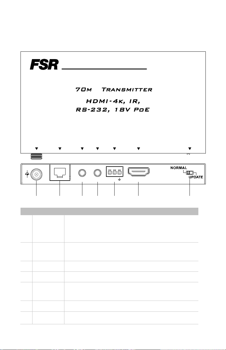
HD-H70-SP-Tx Rear Panel
HD -H70 -SP- Tx
DC18V HDB T OU T HDMI I NRS -23 2IR IN IR O UT
-
+
IR I N IR O UT Tx R x HD MI IN
1 2 3 4 5 6 7
ID Name Description
1 Power
HDBT
2
OUT
3 IR IN Connect to an IR receiver cable.
4 IR OUT Connect to an IR emitter cable.
5 RS-232
Connect to a power supply via a power adapter to either
the transmitter or receiver side 18VDC input.
Note: It is only necessary to power one side (Tx or Rx)
RJ-45 connection to the receiver via a CAT5e/CAT6
CAT6A / CAT7 cable.
Used to connect to a computer to update firmware or
connect a RS-232 control device.
RS -23 2
MODE
6 HDMI IN Connect to a source device via an HDMI cable.
Switch
7
Normal:
7
Page 8

ID Name Description
Mode RS-232 pass through capability enabled
Firmware cannot be updated.
Update:
RS-232 pass through capability disabled
Firmware can be updated.
8
Page 9

HD-H70-SP-Rx Front Panel
FSR HD-H70-SP-Rx
PWR STATUS LINK HDCP
4321
ID Name Description
1 Power LED
2 Status LED
3 Link LED
4 HDCP LED On: HDCP video is being transmitted.
On: Receiver is powered on.
Off: Receiver is powered off.
Blinking: Normal operating condition
Off: Fault
On: Receiver and Transmitter are linked to each
other.
Off/Blinking: Fault in unit(s) or cabling
Blinking: No HDCP video is being transmitted.
9
Page 10
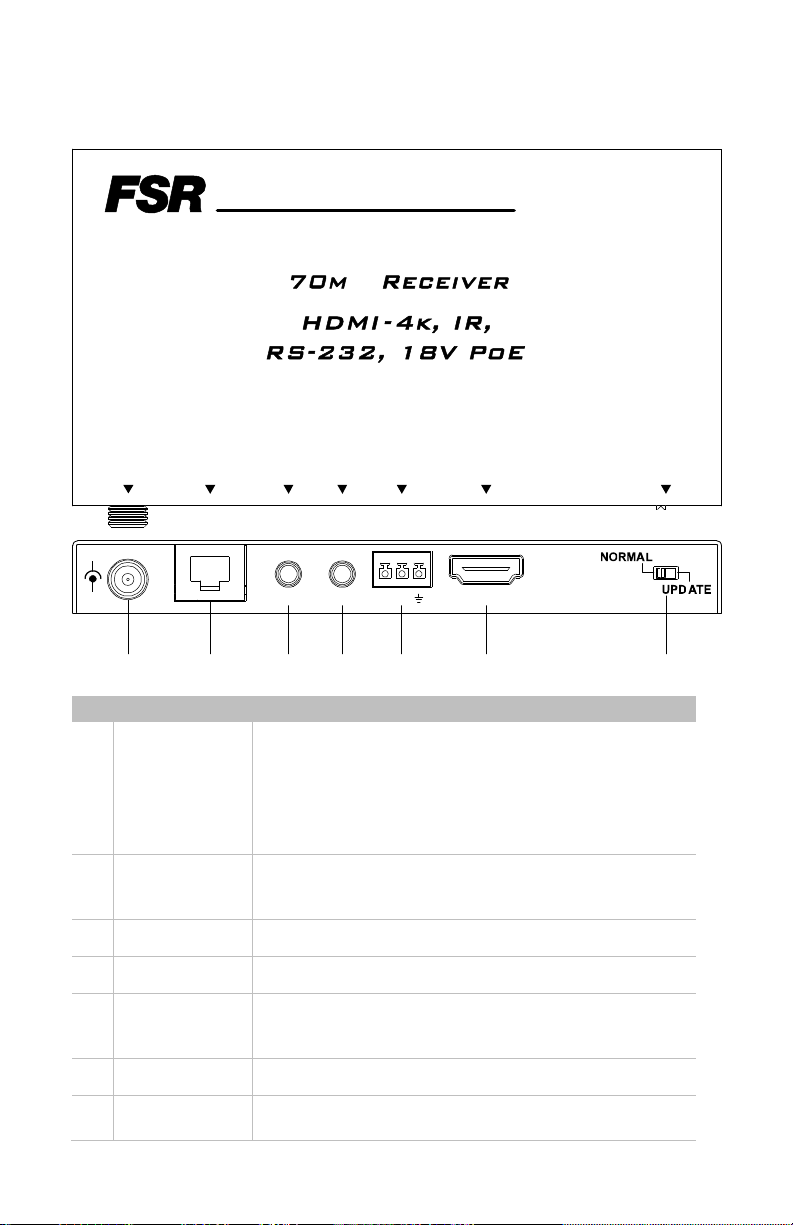
HD-H70-SP-Rx Rear Panel
HD-H70 -SP- Rx
DC18V HDB T IN HD MI OU TRS -23 2IR IN IR O UT
-
+
IR IN IR OUT Tx Rx HDMI OUT
1 2 3 4 5 6 7
ID Name Description
1 Power
2 HDBT IN
3 IR IN
4 IR OUT
5 RS-232
Connect to a power supply via a power adapter to
either the transmitter or receiver side 18VDC input.
Note: It is only necessary to power one side (Tx or
Rx)
Connect to the transmitter via a CAT5e / CAT6 /
CAT6A / CAT7 cable.
Connect to an IR receiver cable.
Connect to an IR emitter cable.
Used to connect to a computer to update firmware or
connect a RS-232 control device.
RS -23 2
MODE
6 HDMI OUT Connect to a Display via an HDMI cable.
7 Mode Switch
Normal:
10
Page 11

ID Name Description
RS-232 pass through capability enabled
Firmware cannot be updated.
Update:
RS-232 pass through capability disabled
Firmware can be updated.
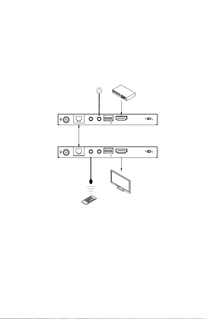
Hardware Installation
Warnings
Before the installation, disconnect the power supply from all the
devices.
Do not connect or disconnect cables from the Transmitter and
Receiver when they are powered on. To connect or disconnect
cables from the units, power them off first.
For best resolution and ESD performance Shielded CAT6A in a TIA
/ EIA 568B wiring configuration is recommended.Please use care
when installing, connecting and disconnecting cables.
1. Connect the source to HDMI IN on the Transmitter via an HDMI cable.
2. Connect an IR emitter cable to IR OUT and an IR receiver cable to IR IN on
transmitter.
3. Connect a Display to HDMI OUT on Receiver.
4. Connect an IR emitter cable to IR OUT and an IR receiver cable to IR IN on
the Receiver.
5. Connect HDBT OUT on the Transmitter to HDBT IN on the Receiver via a
shielded CAT5e / CAT6 / CAT6A / CAT7 cable.
6. Connect the power supply to either the transmitter or receiver.
11
Page 12

HD-H70-SP-Rx
IR RECEIVER
TV REMOTE
HD-H70-SP-Tx
-
+
CABLE
IR IN IR OUT T x Rx HDMI IN
ETHERNET
HDBaseT
IR EMITTER
CABLE
BLU-RAY
DVD
NORMA L
UPD AT E
-
+
IR RECEIVER
CABLE
DVD REMOTE
IR IN IR OUT T x Rx HDMI OUT
IR EMITTER
CABLE
NORMA L
UPD AT E
TV
12
Page 13

IR and RS-232 Operation
HD-H70-SP-Rx
TV REMOTE
IR Control
The IR pass-through function in the Transmitter and Receiver allows you to
control the source from the Display’s location or control the Display from the
source's location.
Scenario 1
In this case, IR IN on the Transmitter is connected to an IR receiver cable and IR
OUT on Receiver is connected to an IR emitter cable. The TV can be controlled
from the Transmitter’s location with the TV remote.
BLU-RAY
DVD
NORMA L
UPDATE
HD-H70-SP-Tx
-
+
IR RECEIVER
CABLE
IR IN IR OUT Tx Rx HDM I IN
ETHERNET
HDBaseT
-
+
IR IN IR OUT Tx Rx HDMI OUT
IR EMITTER
CABLE
NORMA L
UPDATE
TV
13
Page 14
Scenario 2
In this case, IR OUT on the Transmitter is connected to an IR emitter cable and IR
IN on the receiver is connected to an IR receiver cable. The DVD-player can be
controlled from the Receiver's location with the DVD remote.
BLU-RAY
DVD
NORMA L
UPDATE
NORMA L
UPDATE
TV
HD-H70-SP-Tx
-
+
HD-H70-SP-Rx
-
+
IR RECEIVER
IR EMITTER
CABLE
CABLE
IR IN IR OUT Tx Rx HDM I IN
HDBaseT
ETHERNET
IR IN IR OUT Tx Rx HDMI OU T
DVD REMOTE
14
Page 15

RS-232 Control and Firmware Updates
The RS-232 port on the Transmitter or Receiver can be connected to a computer
to update firmware. An RS-232 device can be connected to communicate with
another RS-232 device on the other extender's side via a CATx cable.
Scenario 1: Firmware Update
PC
HD-H70-SP-Tx
-
+
IR IN IR OUT TxRx HDMI IN
Set switch to UP DATE
OR
HD-H70-SP-Rx
-
+
IR IN IR OUT TxRx HDMI OUT
Set switch to UP DATE
Scenario 2: RS-232 Control
RS232 DEVICE
HD-H70-SP-Tx
-
+
HD-H70-SP-Rx
-
+
IR IN IR OUT TxRx HDMI IN
ETHERNET
HDBaseT
IR IN IR OUT TxRx HDMI OUT
RS232 DEVICE
Set switch to NO RMAL
Set switch to NO RMAL
NORMA L
NORMA L
NORMAL
NORMAL
UPDATE
UPDATE
UPDATE
UPDATE
Baud rate max is 115.2 Kbps.
15
Page 16

This page is intentionally blank
16
Page 17

Troubleshooting
Why is the power LED off?
Check that the power supply is powered on.
Check that all the cables are properly connected.
Why is the Link LED off or blinking?
Check that power supplies of all the devices are powered on.
Check that all the cables connected properly.
Check that the length of cable is appropriate. For more information, see
cable specifications in the Specifications section.
Why does the display connected to the Receiver show no picture?
Check that power supplies of all the devices are powered on.
Check that all the cables are connected properly.
Check that the display works properly, and that source device has a
normal signal output.
Check that your Display is switched to the correct source input mode,
such as switching to HDMI 1, HDMI 2, etc.
Check that no compatibility issues exist between Receiver and Display.
If so, replace the Display with another model.
17
Page 18

Why does the Display connected to the Receiver display snow or mosaic?
Check that all the cables are qualified and connected properly.
Check that HDBaseT cables are CAT5e/CAT6 or better cables.
Check that the input sources have no problems, such as snow, mosaic
or a damaged disc. If so, replace them with the normal input sources.
Check that there are no compatibility issues between the Receiver and
Display. If so, replace the Display with another model.
Glossary
ESD Electro-static Discharge
HDBT HDBaseT
HDCP High-bandwidth Digital Content Protection
HDMI High Definition Multimedia Interface
IR Infra-red
LCD Liquid Crystal Display
LED Light Emitting Diode
18
Page 19

Specifications
HD-H70-SP-Tx
Technical
Input 1 x HDMI IN
Input Signal Type HDMI 1.4 with 4K2K
Input Resolution
Support
Input Video Level 0.5-1.2 V p-p
Output 1 x HDBT OUT
Output Signal Type HDBT
Video Impedance
Maximum Pixel
Clock
Operating
Temperature
Storage
Temperature
Power Supply DC 18V 2A with locking connector
Power Consumption HD-H70-SP-Rx powers HD-H70-SP-Tx (or visa
ESD Protection Human-body Model:
Surge Protection IEC 61000-4-4 (EFT) 40A (5/50ns); IEC 61000-4-5
4k 2160p (3840x2160) / 1080P / 1080i / 720P /
576P / 480P / 576i / 480i
100Ω
297MHz
32°F to 95°F (0°C to 35°C)
10% to 90%, non-condensing
-4°F to 140°F (-20°C to 70°C)
10% to 90%, non-condensing
versa): 12.2W for both devices.
±8kV (Air-gap discharge)
±4kV (Contact discharge)
(Lightning) 25A (8/20μs)
19
Page 20

Cable Specifications
For best resolution and ESD performance Shielded CAT6A in a TIA / EIA
568B wiring configuration is recommended.
Cable Type Range Supported Video
CAT5e/CAT6 60 m 1080p 60Hz (36 bpp)
35 m 1080p 60Hz (48 bpp)
1080p 60Hz 3D
4K 2160p (3840x2160@30Hz)
CAT6A/CAT7 70 m 1080p 60Hz (36 bpp)
40 m 1080p 60Hz (48 bpp)
1080p 60Hz 3D
4K 2160p (3840x2160@30Hz)
General
Shipping Weight (set) 2.1 lbs. (0.95 kg)
Dimension (W x H x D)
5.3'' x 0.6''x3'' (135 mm x 14 mm x 77 mm)
Certification FCC, RoHS
20
Page 21

HD-H70-SP-Rx
Technical
Input 1 x HDBT IN
Input Signal Type HDBT
Input Resolution
Support
Input Video Level 0.5-1.2 V p-p
Output 1 x HDMI OUT
Output Signal Type HDMI: HDMI 1.4 with 4K2K
Video Impedance 100Ω
Maximum Pixel Clock 297 MHz
Operating
Temperature
Storage Temperature
Power Supply DC 18V 2A
Power Consumption HD-H70-SP-Rx powers HD-H70-SP-Tx (or visa
ESD Protection Human-body Model:
Surge Protection
4k 2160p (3840x2160) / 1080P / 1080i / 720P /
576P / 480P / 576i / 480i
32°F to 95°F (0°C to 35°C)
10% to 90%, non-condensing
-4°F to 140°F (-20°C to 70°C)
10% to 90%, non-condensing
versa): 12.2W for both devices
±8kV (Air-gap discharge)
±4kV (Contact discharge)
IEC 61000-4-4 (EFT) 40A (5/50ns); IEC 61000-4-5
(Lightning) 25A (8/20μs)
21
Page 22

Cable Specifications
For best resolution and ESD performance Shielded CAT6A in a TIA / EIA
568B wiring configuration is recommended.
Cable Type Range Supported Video
CAT5e/CAT6 60 m 1080p, 60 Hz 36 bpp
35 m 1080p 60 Hz 48 bpp
1080p 60 Hz 3D
4K 2160p (3840 x 2160@30Hz)
CAT6A/CAT7 70 m 1080p, 60 Hz 36 bpp
40 m 1080p 60 Hz 48 bpp
1080p 60 Hz 3D
4K 2160p (3840 x 2160@30Hz)
General
Shipping
2.1 lbs. (0.95 kg)
Weight (set)
Product
Dimension
5.3'' x 0.6'' x 3'' (135 mm ×14 mm ×77 mm)
(W x H x D)
Certification FCC, RoHS
22
Page 23

Limited Warranty
The HD-H70-SP HDBaseT HDMI EXTENDER SET is warranted against failures due to
defective parts or faulty workmanship for a period of three years after delivery to the original
owner. During this period, FSR will make any necessary repairs or replace the unit without
charge for parts or labor. Shipping charges to the factory or repair station must be prepaid by
the owner, return-shipping charges (via UPS Ground) will be paid by FSR.
This warranty applies only to the original owner and is not transferable. In addition, it does
not apply to repairs done by other than the FSR factory or Authorized Repair Stations.
This warranty shall be cancelable by FSR at its sole discretion if the unit has been subjected
to physical abuse or has been modified in any way without written authorization from FSR.
FSR’s liability under this warranty is limited to repair or replacement of the defective unit.
FSR will not be responsible for incidental or consequential damages resulting from the use
or misuse of its products. Some states do not allow the exclusion of incidental or
consequential damages, so the above limitations may not apply to you. This warranty gives
you specific legal rights, and you may also have other rights which vary from state to state.
Warranty claims should be accompanied by a copy of the original purchase invoice showing
the purchase date (if a Warranty Registration Card was mailed in at the time of purchase,
this is not necessary). Before returning any equipment for repair, please read the important
information on service below.
SERVICE
Before returning any equipment f or repair, please be sure that it is adequately packed and
cushioned against damage in shipment, and that it is insured. We suggest that you save the
original packaging and use it to ship the product for servicing. Also, please enclose a note
giving your name, address, phone number and a description of the problem.
NOTE: all equipment being returned f or repair must have a Return authorization (RMA)
Number. To get a RMA Number, please call the FSR Service Department (1-800-332-FSR1).
Please display your RMA Number prominently on the front of all packages.
CONTACT INFORMATION:
FSR INC.
244 Bergen Blvd.
Woodland Park, NJ 07424
Phone: (973) 785-4347
Order Desk Fax: (973) 785-4207
Web Site: http://www.fsrinc.com
23
Page 24

 Loading...