


LIT1368E Flex Training Manual
FSR
FLEX CONTROL BUILDER
Training Exercise Manual
Table of Contents
Contents
NEW FEATURES WITH THE FLEX CONTROL BUILDER ................................................................................................3
FLEX CONTROL BUILDER INSTALLATION ..........................................................................................................................4
UPDATES ................................................................................................................................................................................................4
INTRODUCTION..................................................................................................................................................................................5
THE SYSTEM.........................................................................................................................................................................................6
WORKING WITH THE FLEX CONTROL BUILDER .............................................................................................................8
CONFIGURE THE FLEX ....................................................................................................................................................................9
OPTIONS .................................................................................................................................................................................................9
ACTION EDITING ...............................................................................................................................................................................9
PROJECT PROPERTIES ................................................................................................................................................................. 13
NOTES ................................................................................................................................................................................................... 14
POWER UP .......................................................................................................................................................................................... 14
AUTO PRESS BEEP ........................................................................................................................................................................ 14
AUTO ALTERNATE GRAPHIC ................................................................................................................................................... 14
LCD BRIGHTNESS ........................................................................................................................................................................... 14
LCD DIM .............................................................................................................................................................................................. 14
SPLASH SCREEN SET UP ............................................................................................................................................................. 15
LIBRARIES .......................................................................................................................................................................................... 15
ADDING DEVICES ............................................................................................................................................................................ 15
SERIAL DEVICE ................................................................................................................................................................................ 18
Page | 1
32600 LIT1368F

LIT1368E Flex Training Manual
COM PORT .......................................................................................................................................................................................... 19
IR DEVICE ........................................................................................................................................................................................... 21
ADD NEW ETHERNET DEVICE ................................................................................................................................................ 24
SERIAL PORTS .................................................................................................................................................................................. 29
DEFINE SCREENS ............................................................................................................................................................................ 30
SAVE PROJECT .................................................................................................................................................................................. 40
GLOBAL BANNER SET UP ........................................................................................................................................................... 49
ASSIGN ACTIONS TO GLOBAL BANNER ............................................................................................................................. 54
VOLUME.......................................................................................................................................................................................... 58
ASSIGNING ACTIONS ............................................................................................................................................................... 60
GROUPS ................................................................................................................................................................................................ 62
BUTTON TOUCH TYPES .............................................................................................................................................................. 62
BEEP ...................................................................................................................................................................................................... 76
VIRTUAL BUTTON PRESS........................................................................................................................................................... 77
VIRTUAL BUTTON STATE .......................................................................................................................................................... 78
WAIT ...................................................................................................................................................................................................... 80
COUNTERS .......................................................................................................................................................................................... 81
MESSAGE BOX SET UP.................................................................................................................................................................. 92
KEEP OPEN ................................................................................................................................................................................... 92
CLOSE AFTER PRESS ............................................................................................................................................................... 92
CLOSE AFTER TIME .................................................................................................................................................................. 92
PASS-THROUGH COMMAND ..................................................................................................................................................... 96
WAIT FOR RESPONSE ............................................................................................................................................................... 100
FLAGS ................................................................................................................................................................................................. 100
SEND INLINE IP COMMAND ................................................................................................................................................... 102
LOG COMMAND ............................................................................................................................................................................ 106
SET/CLEAR GPIO ......................................................................................................................................................................... 107
LCD BRIGHTNESS CONTROL ................................................................................................................................................. 112
TOUCH LOCKOUT ........................................................................................................................................................................ 114
DATE/TIME WINDOW .............................................................................................................................................................. 115
FLEX CONNECT ............................................................................................................................................................................. 116
Page | 2
32600 LIT1368F

LIT1368E Flex Training Manual
DEFAULT IP ADDRESS .............................................................................................................................................................. 116
ENABLE/ DISABLE SYNC ......................................................................................................................................................... 118
LOG COMMAND ............................................................................................................................................................................ 122
EVENTS ............................................................................................................................................................................................. 123
USING THE SCHEDULER ..................................................................................................................................................... 123
USING POWER UP ACTIONS................................................................................................................................................... 127
DELETING DEVICES.................................................................................................................................................................... 129
CONTROL LIBRARIES ................................................................................................................................................................ 131
INPUT WINDOWS ........................................................................................................................................................................ 132
INPUT WINDOWS ........................................................................................................................................................................ 133
ERROR CHECKING ....................................................................................................................................................................... 138
ALIAS .................................................................................................................................................................................................. 139
INDEX ................................................................................................................................................................................................. 142
New Features with the Flex Control Builder
Fully downward compatible with Flex Configurator Projects.
Custom graphics for screens as well as buttons.
Resize button graphics.
Move or resize buttons on a window or screen, and not lose commands underneath.
Custom alternate button graphics feature as well.
Option to place buttons and text outside of templates.
Drag and drop Tree View configuration.
End user: Time / Date setting capability.
Input window (Dialers supported).
Easier synchronization of Flex panels.
Built in diagnostic to help prevent ADF errors.
Multiple Bar Graph placement and device assignment.
ADF file viewer built in.
Project history. Reload up to 4 previously loaded projects.
Load multiple projects into Flex Control Builder and click between the projects.
Save projects to any location.
Retrieve projects from anywhere they are stored.
Simplified library building.
Page | 3
32600 LIT1368F

LIT1368E Flex Training Manual
Single click FSR website for updates to Flex Control Builder, Library files, or Firmware.
Single page Flex panel status.
Faster uploads and downloads of projects.
Full functionality of all 4 serial ports.
IR Pass Thru. IR signal received at front Flex panel will be repeated out all 4 IR ports of the
Flex. This feature can be turned on or off through command line actions.
Computer font magnification level does not interfere with pixel coordinates of project.
Log file action commands on Flex connection screen.
Action markers added to reveal buttons where commands have been assigned.
Copy and Paste screens from one project to another.
Flex Control Builder Installation
Run the installer program as System administrator and use the default settings. The Flex Control
Builder program will not overwrite or uninstall any previously created projects created with the
Flex Configurator program. While a new Project Folder will be created with this install, any
previously created projects can be imported into the Flex Control Builder.
UPDATES
Page | 4
32600 LIT1368F

LIT1368E Flex Training Manual
The above screen is available from the ABOUT screen of the program. Please refer back to this often
and check for Program, Library, and Firmware updates.
The first time the Flex Control Builder is started, you should check for program updates, and you
must click on Get Library Update to download all of the available library files.
TRAINING
REQUIREMENTS
This is a hands-on exercise to familiarize the technician with the entire FLEX system. Before you
begin it is important to have the proper functioning equipment. You will need the following: FLEX
LT-200 Control Panel, Flex Control Builder Software, Laptop or Desktop Computer with a Serial
Port or Functioning USB to Serial Converter Operating System, or an IP connection on a network
within the same domain as the Flex panel: Windows 8, Windows 7, or Vista.
IMPORTANT NOTE: Prior to the exercise be sure the Flex Control Builder is properly installed and
communication between the computer and the FLEX panel is tested, and fully functioning.
INTRODUCTION
In this module of the FLEX training program we will follow a step by step process to create a Project
and download it to a Flex control system. A Project defines how the Flex panel will look as well as
how it will behave.
The first step to creating a project is to define what devices are being used, how they will be
connected together and determine what capabilities of a device we want the Flex to control.
Page | 5
32600 LIT1368F

LIT1368E Flex Training Manual
THE SYSTEM
Below is a diagram of the AV system that we want to control. As you can see it is a simple system
with a projector, DVD/VCR player and Laptop PC.
The next step in creating a FLEX project is to make some decisions on which devices we want
control. We have created a simple checklist which will allow you to visually see all of the screens
that you will need for each device that you want to control.
Page | 6
32600 LIT1368F

LIT1368E Flex Training Manual
In this system we will use the FLEX to control the projector as our switcher. It will also handle
volume control. We will add screens to control the DVD/VCR Player
Okay let’s get started.
The first step is to open the Flex Control Builder. The steps we are going to follow to build this
project are as follows:
1. Configure the FLEX
2. Load the Device Libraries
3. Create our screens
4. Add buttons to our screens
5. Assign commands to the buttons
6. Download our project to the FLEX.
Page | 7
32600 LIT1368F

LIT1368E Flex Training Manual
WORKING with the Flex Control Builder
This is the first screen you see when you open the Flex Control Builder program.
Page | 8
32600 LIT1368F

LIT1368E Flex Training Manual
CONFIGURE THE FLEX
Options
You may select various options for how the Flex Control Builder will handle your project locations.
You can select between the Application dialog and Windows Folder Browser styles.
Additionally, default folder Locations can be specified as well as Action Editing.
Action editing
Action editing is merely and editing tool which allows for the positioning of new command
functions based on where the curser is positioned when the command is added. This will make
more sense later on and in more advanced project creation.
Page | 9
32600 LIT1368F

LIT1368E Flex Training Manual
Click on the “New Project” button.
Page | 10
32600 LIT1368F

LIT1368E Flex Training Manual
Here the Parent folder for your projects may be changed or you may keep the new default folder.
Click the NEW button and type in a name for the new Project.
Let’s give our project a name. For this example I’m going to use Flex Exercise 2.0. Enter the name in
the project name window and click set new project.
Page | 11
32600 LIT1368F

LIT1368E Flex Training Manual
Click OK, Note a new folder has been created named Flex Exercise 2.0.
Now click OK again.
Page | 12
32600 LIT1368F

LIT1368E Flex Training Manual
Project Properties
Page | 13
32600 LIT1368F

LIT1368E Flex Training Manual
As with most windows applications, standard full screen, and resizing of screens and column
widths apply here as well. You may want to make the CU full screen and widen the columns for
easier display. Additionally, to widen the Library Tree or the Project Tree, click on either of those
tabs on the top of the column and they will expand so all the contents can be read in full. Clicking
again will return the column to its original size.
Notes
The large notes area is used to enter information about the project we are working on. From here
we can also set up a few global Characteristics of the Flex as well as define how the Flex will operate
under certain conditions.
POWER UP
With this feature set to Yes, the FLEX will perform a series of actions when power is applied to the
panel. This is commonly used to reset the system to a predetermined state after a power failure.
This will be discussed in more detail later on as well.
AUTO PRESS BEEP
This sets the FLEX to provide audio feedback when any button is pressed.
AUTO ALTERNATE GRAPHIC
This sets the FLEX to show an alternate color button with a button press.
LCD BRIGHTNESS
This sets the level of brightness for the LCD panel in a range from 60% down to 1%. The actual full
brightness as determined when the Flex was developed was 60%, It was considered washout at any
brightness level above that. Earlier versions of the program had 100% listed on the configuration
page. In reality that was setting the Flex panel to 60% brightness. This version of the FCB will give
the programmer and end user much more control over brightness so it was decided to show the
actual brightness levels.
LCD DIM
The LCD can be set to dim when the panel has not been used for a predetermined period of time
after the last button press. It will dim to 50% of the LCD BRIGHTNESS setting.
Page | 14
32600 LIT1368F

LIT1368E Flex Training Manual
SPLASH SCREEN SET UP
The Splash screen is a full screen graphic image. It can be a school or corporate logo or any other
graphic. Splash screens can be displayed at power-up as well as be used when the Flex is in standby
mode. In this area, there are two options. The first simply asks if the Project will have a splash
screen. The second asks if you want the Splash screen displayed until it is pressed (Yes) or if you
choose (No) then it will be displayed for a predetermined period of time.
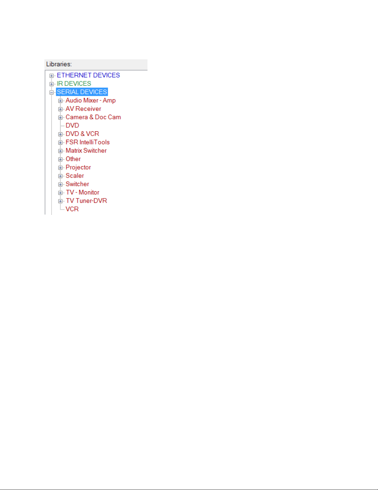
Libraries
ADDING DEVICES
TIP: To quickly widen the Library tree or the Project tree, simply click on the column header. This
will widen the column to the largest width of text within the tree and branches.
From the Library tree, select SERIAL DEVICES and then Projector. Now click on the Hitachi _CPX306 and while holding the left mouse button down, drag the device to the Project tree and drop
the device anywhere within the project tree.
Page | 15
32600 LIT1368F
LIT1368E Flex Training Manual
Page | 16
32600 LIT1368F

LIT1368E Flex Training Manual
Page | 17
32600 LIT1368F

Serial Device
LIT1368E Flex Training Manual
Page | 18
32600 LIT1368F

LIT1368E Flex Training Manual
Com Port
Select Port from drop down list.
Page | 19
32600 LIT1368F

LIT1368E Flex Training Manual
To change the name of the device or any port settings, click on the Change Name and Port box.
If there were any device library notes entered by this particular library creator, they will be
displayed in the Device Library Notes box.
Page | 20
32600 LIT1368F

LIT1368E Flex Training Manual
IR DEVICE
From the Library tree, select IR DEVICES and then Media Player. Now click on the Panasonic_DVDVCR and while holding the left mouse button down, drag the device to the Project tree and drop the
device anywhere within the project tree.
Pick Panasonic_DVD-VCR from list and drag it to the Project Tree.
Page | 21
32600 LIT1368F

Rename to DVD/VCR
LIT1368E Flex Training Manual
Page | 22
32600 LIT1368F

LIT1368E Flex Training Manual
Select Port from drop down list.
To change the name of the device or any port settings, click on the Change Name and Port box.
If there were any device library notes entered by this particular library creator, they will be
displayed in the Device Library Notes box.
Page | 23
32600 LIT1368F

LIT1368E Flex Training Manual
Add New Ethernet Device
The process is similar to adding an IR device or a serial device.
The differences are as follows:
While this project will not utilize an Ethernet type device, we will enter one to show a typical setup.
From the Library tree, select ETHERNET DEVICES and then matrix Switcher. Now click on the
FSR_PATHFINDER and while holding the left mouse button down, drag the device to the Project
tree and drop the device anywhere within the project tree.
Page | 24
32600 LIT1368F

LIT1368E Flex Training Manual
To change the name of the device or any port settings, click on the Change Name and Port box.
If there were any device library notes entered by this particular library creator, they will be
displayed in the Device Library Notes box.
Page | 25
32600 LIT1368F

LIT1368E Flex Training Manual
An IP address and port number have to be added. Additionally the Persistent or the UDP protocol
for the device must be set.
Persistent, if selected, has a timeout set to 1 minute. This is here to allow the user to set the
connection timeout of any misbehaving Ethernet devices. The default setting should remain as is
unless instructed to change it by FSR Customer support or the manufacturer of the device you are
trying to control.
TCP or Transmission Control Protocol and UDP or User Datagram Protocol: TCP is the default
protocol however; UDP may be selected for devices requiring such connectivity. When UDP is
selected, the persistent setting is automatically turned off.
Page | 26
32600 LIT1368F

LIT1368E Flex Training Manual
Page | 27
32600 LIT1368F

LIT1368E Flex Training Manual
Page | 28
32600 LIT1368F

LIT1368E Flex Training Manual
Serial Ports
Click on Serial ports on the Project tree.
Select individual Serial ports in order to change any of the ports parameters.
Serial port 4 is restricted to a MAX baud rate of 57600. None of the other ports are restricted.
We have now completed our device setup.
Page | 29
32600 LIT1368F

LIT1368E Flex Training Manual
DEFINE SCREENS
Now we are going to build the screens that we require for this Project.
From the Library tree, select a Screen Template to be used as the splash screen. Screen empty0, and
Screen template 0 and are typical templates for the splash screen. Keep in mind that Screen
Template0 will not allow buttons to be added. Therefore, use of this template should be used for
Splash screens or screens that do not require button commands.
Select by left clicking on the template and dragging it and then dropping it over the Project tree.
Page | 30
32600 LIT1368F

LIT1368E Flex Training Manual
I selected Splash screen template 1. Once dropped onto the project tree the above screen appears
allowing you to rename the screen if you like for clarity purposes later on. Renaming is not
mandatory and the screen name can be changed at any time later on while building the propject.
This screen has been renamed Splash.
Page | 31
32600 LIT1368F

LIT1368E Flex Training Manual
Typically a splash screen will consist of a background and possibly some text.
Backgrounds can be selected from the FSR stock folder, a Custom folder or a Solid Color
Page | 32
32600 LIT1368F

LIT1368E Flex Training Manual
Solid color will present the following screen to choose from.
Selecting custom folder will show a Change Folder button to press. You will then be able to select a
folder where you have custom graphics. These graphics only need to be BMP, JPG, or GIF formatted
graphics. The CU will automatically resize the graphic for the background.
Page | 33
32600 LIT1368F

LIT1368E Flex Training Manual
Once a background has been selected, you may add a label to the screen. Notice the small vertical
boxes. They are standard text place holders. These place holders are used throughout the CU.
However, this version of the CU does not limit you to using the place holders. Text can be put
anywhere on the screen. The template is provided for ease of use.
To add a label, click on the yellow New Label box and drag and drop it either on a place holder of
anywhere else you desire. If you are not using the template you may find clicking on the Show Grid
box helpful for aligning text. Again this feature is available throughout the CU for text and button
placement.
Page | 34
32600 LIT1368F

LIT1368E Flex Training Manual
Above shows two text boxes added. The one in the middle is selected and you can now change the
color, Font, Style, size and text within the box. Once complete select the other text box and select
Page | 35
32600 LIT1368F

preferences and text.
LIT1368E Flex Training Manual
Click on Final tab and see how the final screen looks.
Page | 36
32600 LIT1368F

LIT1368E Flex Training Manual
Next select screen template 4. This will be used for our HOME screen. Note below it appears as
Screen 2
Let’s rename it HOME
Page | 37
32600 LIT1368F

Now click OK
LIT1368E Flex Training Manual
We can add all the screens we will be using in our project now or start populating the screens as we
go. I prefer to define all the screens ahead of time so I have a good reference. As such I will now add
my DVD screen. Select Screen template 7 for this and drag and drop it to the Project Tree.
Now rename it DVD
Page | 38
32600 LIT1368F

LIT1368E Flex Training Manual
Now select another Screen template 7 and drag and drop it to the Project tree and rename it VCR
Now select Screen template 3 and drag and drop it to the Project Tree and rename it Laptops
Page | 39
32600 LIT1368F

LIT1368E Flex Training Manual
Now add a test screen that can be populated with buttons to further define action items which will
not necessarily be part of the basic project being built here.
Select Screen template 1 and drag and drop it to the Project Tree. Rename it Test.
Save Project
This is a good time to do a project save. Click the save button to save the contents of the current
project. Save As will prompt to create a new project folder similar to when this project was first
named.
Click OK to overwrite the contents of the folder with the additional information added since the
project was started.
Page | 40
32600 LIT1368F

LIT1368E Flex Training Manual
A confirmation screen will follow shortly
All the screens are now added and we will go back to each one and add background, buttons,
banner, and text as applicable.
Since the splash screen has already been designed, pick the home screen from the Project Tree list.
Click on the Banner tab and select the type of banner to use. Since this is the HOME screen, pick the
use Banner Graphics No Home.
Now click Background tab and select a background as we did in the Splash Screen.
Again choose from Standard, Solid Color or Custom.
Page | 41
32600 LIT1368F

LIT1368E Flex Training Manual
Click on the Button Tab and then select Small. This will show the standard Small button library.
Again, you can pick Solid Color for solid color buttons or Custom. Custom will allow you to select a
different folder of graphics and allow you to place a custom graphic into any template location, or
any other position on the screen. Additionally, these buttons can be re-sized following conventional
windows graphics techniques.
Page | 42
32600 LIT1368F

LIT1368E Flex Training Manual
Procedurally, Custom buttons and solid colors are selected in a similar manner as custom
backgrounds. The difference being the ability to re-size the button graphic once it has been
dropped onto the screen.
This exercise will use standard buttons. Select the button and drag, then drop it to the
top left corner template box. When dragging and dropping buttons, use the top left corner of the
graphic as a guide to dropping the graphic. Once the top left corner is within the template box, the
mouse button can be released and the button will automatically be centered and re-sized if
necessary.
Additionally, notice to the right of the template screen there are 3 boxes that can be checked. Show
grid will present a grid pattern which is very helpful in aligning buttons outside of the template. The
show Alternate box is used to reveal the alternate graphic of a button. Notice this exercise is using
the Blue Square as the primary color and red Square as the alternate. To change either primary or
alternate color, select from the drop down menu and drag and drop the new graphic accordingly.
Should a custom graphic been used, this will also reveal the custom graphic used as the alternate.
Click on Large for the large button selections and fill in the remainder of the screen by dragging and
dropping the graphics as shown below. Note the Blank button.
Page | 43
32600 LIT1368F

LIT1368E Flex Training Manual
Now click on the Label Tab.
Notice the small verticle rectangular place holders. The labeling process is the same as was
instructed for the Splash screen.
Page | 44
32600 LIT1368F

LIT1368E Flex Training Manual
Drag a new label to the blank button, Pick a color (White) and label it TEST. Then Label the screen
as shown below (HOME)
Page | 45
32600 LIT1368F

LIT1368E Flex Training Manual
The Bar Graph, and Input Window tabs will be discussed later in this exercise. They are more
advanced and are not part of the basic project being built right now. Select the Final tab to show
exactly how the screen will look.
Page | 46
32600 LIT1368F

LIT1368E Flex Training Manual
Complete the DVD, VCR, Laptops and TEST screens in a similar manner using the following screen
shots as a guide.
Note, for the following screens the Use Full Banner Graphics option will be chosen.
Page | 47
32600 LIT1368F

LIT1368E Flex Training Manual
Page | 48
32600 LIT1368F

LIT1368E Flex Training Manual
Note: On the test screen below, the numberd buttons were selected directly from the available
standard buttons and the Large ABCD buttons were the large blank button and a label was added to
each.
GLOBAL BANNER SET UP
Global banners are designed to eliminate repetitive steps when configuring audio controls. When
used the Flex Control Builder designates the 5 buttons across the screen as Home, Mute, Volume
Page | 49
32600 LIT1368F

LIT1368E Flex Training Manual
down, a volume ramp and volume up. The global banners set-up is tabbed to work left to right as
the banner is configured. Select the second tab BAR GRAPH STYLES.
We already chose the banner type we want to use on our screens, now we can define the graphic
options and function assignments to the banner.
Page | 50
32600 LIT1368F

LIT1368E Flex Training Manual
Select the style of banner, Interior color of Bar Graph, and the Primary and Alternate Color schemes.
Depending on the device properties, the Top value, Bottom value, Initial value and Step size can be
changed.
Page | 51
32600 LIT1368F

LIT1368E Flex Training Manual
Clicking on the final tab or the Show Controls will show how the banner will look on all screens
where banner has been selected for use.
Page | 52
32600 LIT1368F

LIT1368E Flex Training Manual
Labels can be setup in the same manner as shown earlier for buttons.
Input windows will be discussed in more detail later as well.
Page | 53
32600 LIT1368F

LIT1368E Flex Training Manual
Clicking Final will reveal the final layout of the banner. By also checking off the Show Alternate box,
the alternate color for each button will be displayed.
Assign Actions to Global Banner
To assign or review default actions for buttons, Click on the + next to the Global banner in the
Project. This will reveal the banner buttons and numbers. Click on the banner BarGraph.
Page | 54
32600 LIT1368F

LIT1368E Flex Training Manual
Note the Banner BarGraph is now hi-lighted and the set of actions list is now visible.
Now let’s complete the BANNER FUNCTIONS.
Page | 55
32600 LIT1368F

LIT1368E Flex Training Manual
Select Home Actions Tab.
Click on the Go To Screen command, HOME, and then press the save button.
Page | 56
32600 LIT1368F

LIT1368E Flex Training Manual
Now select the Mute Actions Tab.
Select Send command, select projector and then ‘AUDIO MUTE ON’ and press OK
Now select the lower box and repeat steps for ‘AUDIO MUTE OFF’
Page | 57
32600 LIT1368F

LIT1368E Flex Training Manual
Volume
Volume controls are versitle. They offers the capability of independently controlling
volume press actions and hold actions and has a separate Volume release action set of
commands should a particular device require it.
To differentiate, the Volume up press command will require the user to repeatedly touch
the volume up button in order to increase volume. However if the same volume up
command is repeated in the Volume Up Hold Actions, the user can press and hold the
volume up button in order to increase volume. Likewise the volume down command
window works the same way.
First click in the volume up press actions box, and then click on send Command from
available actions.
Completed screen will look like this.
Page | 58
32600 LIT1368F

LIT1368E Flex Training Manual
Note: Some devices require a release action for volume control. If required, enter the
command in the Volume Up release actions.
Now click on the Volume down tab and enter the volume down actions as you did for the
volume up.
Page | 59
32600 LIT1368F

LIT1368E Flex Training Manual
Assigning Actions
Now we have to go back and assign actions to the graphic buttons. Note: Assigning actions can be
done at any previous point where the graphic screen was laid out. We are following this order for
clarity sake and to keep like actions together.
Since the Splash screen does not allow any buttons, the first screen where we may add actions is the
Home screen. Notice the screens in the Project Tree now have the + symbol in front of them. Click
the + in front of the Home screen.
All the buttons added to the Home screen are now revealed in the tree. Select Button 1
Page | 60
32600 LIT1368F

LIT1368E Flex Training Manual
Notice the System power button is selected and on the screen it is outlined.
Before we begin assigning actions, the options on the screen need to be defined:
Go To Parent button will bring the attention back to the graphic design screen where the buttons
can be added, changed or deleted. Should you do so, return to this screen either by clicking the
Button 1 in the project tree or by clicking the Go To Action button on the Button Screen.
Page | 61
32600 LIT1368F

LIT1368E Flex Training Manual
Groups:
When a Normal button is part of a group, and it is pressed, the alternate graphic is shown
until another button within the group is pressed. This is used with source select buttons.
On a transport control screen we want only one button pressed at a time. When any of the
buttons are pressed, its alternate graphic is displayed until any other button in the group is
pressed at which point, the first button will go back to its main graphic and the 2nd button
pressed will show the alternate graphic. In this exercise, the DVD, VCR and PC screens will
be in group 1.
Attach Flag will be discussed in detail later on in this exercise as it is a more advanced
feature not used in this basic project being worked on.
The Format button will simply re-format the actions entered for reviewing purposes.
Button touch types:
There are four different Button Touch Types. The first type is a normal button. When the
button is pressed the actions that are listed in the window on the right are executed. Also,
when the button is pressed, the alternate graphic is shown briefly to visually acknowledge
the press. The exception to this is when Normal buttons are part of a group.
Page | 62
32600 LIT1368F

LIT1368E Flex Training Manual
The next type is Press / Release. When the button is pressed, the actions in the Press
Action window are executed. When you remove your finger from the button, the actions in
the Release Actions window are executed. You do not have to populate a Press / Release
button with Press and Release actions. When a Press / Release button is pressed, the
alternate graphic is shown until the button is released.
The third type of button is a Press / Hold / Release button. In this case the Press actions
occur when you press the button. If you hold the button for more than ½ second, the Hold
actions occur repeatidly until you remove your finger from that button. At that point, the
Release actions occur. It is not necessary to populate the Press, Hold and Release areas.
They can be used in any combination to achieve the desired effect. When a Press / Hold /
Release button is pressed, the alternate graphic is shown until the button is released.
The final button type is a Toggle Button. A Toggle Button is one that you press once to do
something and press again to do something else. In this case, the First Press Actions occur
the first time that the button is pressed. When the button is pressed again, the Second Press
Actions occur. Press the Toggle Button Tab to see this type.
Note: Whichever style is selected Toggle or Press / Hold / Release, the style selected last
will be the style saved to the project. That is to say that if you selected a press action, filled
in some actions and then decided to make it a Toggle style button and fill in actions there,
the Toggle will be the one saved to the project. There is no need to delete the actions in the
press window as long as the toggle was last selected before going on to the next button to
add actions to.
Page | 63
32600 LIT1368F

LIT1368E Flex Training Manual
Above: Press Hold and action boxes
Below: Toggle Low to High and High to Low action boxes.
Page | 64
32600 LIT1368F

LIT1368E Flex Training Manual
Now we will start to add real actions.
Select button 1 again (System Power). Since we want one set of actions to “Turn the System On”
and another set to “Turn the System Off”, we will setup the System Power button as a toggle button.
Select the Toggle button type.
This button operates by itself, so select No under Button Group Number.
Notice the 2 Action windows, Low to High and High to Low.
Page | 65
32600 LIT1368F

LIT1368E Flex Training Manual
Click within the Low to High box first.
Click on Send Command.
Click on Projector.
Select ‘Projector’ ‘Power On’. This will tell the projector to switch on.
Click on the ‘OK’ button.
Click on Send Command.
Page | 66
32600 LIT1368F

LIT1368E Flex Training Manual
Click on DVD VCR
Select ‘DVD VCR’ ‘POWER’
Click the ‘OK’ button.
In the Second Press Actions window reverse the process.
Following the same steps used above, click on the High to Low Window and do the following:
Send a command to the projector to power off.
Send a command to the DVD VCR to power off.
When completed the window will look like this.
Click on the DVD button.
Page | 67
32600 LIT1368F

LIT1368E Flex Training Manual
Select a Normal Button Type.
Select Group 1 then click on the Send Command
.
Click Send Command then select DVD/VCR Device.
Page | 68
32600 LIT1368F

LIT1368E Flex Training Manual
Select ‘MODE DVD’. This command will tell the DVD VCR to switch to the DVD Mode.
Note: The enter Repeat IR Code Times. Some IR devices require the code to be sent out
multiple times. Should this arise, set the number of repeats here. This is also an editable
item which you can go back to at a later time if necessary.
Click the ‘OK’ button.
Click on Send Command.
Select Projector.
Select the command ‘COMPONENT INPUT’.
Page | 69
32600 LIT1368F

LIT1368E Flex Training Manual
Click the ‘OK’ button.
Click on Go to Screen.
Select DVD.
Click the ‘SAVE’ button.
The completed DVD button should look like the following.
The input screen will look like this.
Page | 70
32600 LIT1368F

LIT1368E Flex Training Manual
Now select the VCR button and perform similar actions to the DVD however this time select the SVIDEO INPUT, DVD VCR Mode VCR and the GOTO screen will be VCR.
The PC screen will only be placed into Group 1 and have a command to GOTO the laptop screen as
shown below.
Page | 71
32600 LIT1368F

LIT1368E Flex Training Manual
The TEST button will only use the GO TO screen command. Choose the TEST screen from the GO TO
Screen list.
The home screen is now complete and we can move on to the DVD button commands.
Click on the + to the left of the DVD in the Project Tree and select Button 1.
Page | 72
32600 LIT1368F

LIT1368E Flex Training Manual
The button types, and command options are the same as the previous screen.
Starting with the Play button we will then click the Send Command, select the DVD VCR,
and click the Play
Page | 73
32600 LIT1368F

LIT1368E Flex Training Manual
Repeat this for all of the other buttons on the page.
Note: You have the option to put any or all of the buttons into groups if you want to display the last
option selected such as a stop or pause. Again since this is an IR command there is also the Repeat
Option if the device requires it.
Click on the +VCR and select Button 1 and repeat the commands in a similar manner as was done
for the DVD screen.
Once completed, click the +PC screen
This one will be a little different since we have two PC inputs to select from.
Click Button 1
Page | 74
32600 LIT1368F

LIT1368E Flex Training Manual
This will be a normal button press action. Select group 1, click on send Command, select Projector
and then select PC1 INPUT.
Now select PC 2, select group 1 again, then send command and select PC2 INPUT.
This completes the basic screens for a project. Next we will select the TEST screen and define all of
the other command actions available.
Page | 75
32600 LIT1368F

LIT1368E Flex Training Manual
BEEP
A beep command can be added to any buton press or event. To demonstrate this, click the
+TEST on the Project Tree and then button 1 on the Project Tree which is the A button on
the screen.
This will be a press only action. On the command list, click the BEEP command.
This command tells the Flex to beep. This can be used at anytime to provide audible
feedback. For example, if you turn Auto Press Beep off, but you want certain buttons to
beep to provide feedback, you can add the beep command to those buttons.
Page | 76
32600 LIT1368F

LIT1368E Flex Training Manual
Virtual Button Press
Virtual button press gives the user the ability to invoke actions without an actual button
press. For example, when you pressed the mute button on one screen, you want the mute
button to appear selected on all other screens and visa versa.
Page | 77
32600 LIT1368F

LIT1368E Flex Training Manual
For ease of explanation, we will setup a virtual button press and virtual button state to
power our system on and off from the TEST screen.
Select the B button. This will be a toggle button type so click on the toggle tab to enter
actions.
Now select virtual button press from the actions list.
Select the Home screen rom the list and then click on the System Power button on the
HOME screen displayed on the right.
Click OK
Now click into the actions box labeled High to Low and repeat the commands above to
perform a Power off now.
Virtual Button State
Now that the virtual button has been set, we want to show the state of the virtual button
pressed.
Click back into (Low to High) box and then click on Virtual button state command.
Now click on the HOME screen.
Click on the System Power button. By default, the Set State to 1 is selected as shown below.
Page | 78
32600 LIT1368F

LIT1368E Flex Training Manual
Click OK
Now click into the Second Press Actions (High to Low) box and select Virtual Button State
again.
Select home and then the System Power Button again.
This time click on Set State to 0 and press the OK button.
The screen will now look like the screen below.
Page | 79
32600 LIT1368F

LIT1368E Flex Training Manual
Wait
The FLEX can be told to wait for a predetermined period of time. This has the effect of
pausing the execution of the list of actions in a button. You can delay the next action from 1
millisecond to 100 seconds. This can be added between any commands. This is commonly
used between commands to allow the device time to process the prior command before
Page | 80
32600 LIT1368F

sending a new one.
LIT1368E Flex Training Manual
Counters
First let’s look at how counters and flags are used. In this example we will be doing a very
simple command set which will set a counter to increment by 1 each time the button is
pressed, and then once the counter equals 5 we will have the flex panel beep once, go to the
splash screen, then wait there for 2 seconds, and then return to the Home screen and zero
out counter 1.
Select Button C on the TEST screen.
Now click on the Counters action command.
Select counter
Select COUNTER 1 and then select increment and put in a value of 1.
Page | 81
32600 LIT1368F

LIT1368E Flex Training Manual
Page | 82
32600 LIT1368F

LIT1368E Flex Training Manual
Click OK
Page | 83
32600 LIT1368F

LIT1368E Flex Training Manual
Page | 84
32600 LIT1368F

LIT1368E Flex Training Manual
Now select Conditional
Select Counter again. Then select COUNTER 1 and select >= and set the value to 5.
Click on the Next> button
Now we will add an action. Under “Add Actions to perform”, select Beep.
Now we will go to the splash screen. Click on “Go To Screen” and select “Splash Screen”
We will also add a wait state. Click on wait and enter 2 seconds.
Page | 85
32600 LIT1368F

LIT1368E Flex Training Manual
Now select “Go To Screen” and select “TEST”.
Now we will clear the counter. Select “Flags/Counters” and set Counter 1 to 0.
Page | 86
32600 LIT1368F

LIT1368E Flex Training Manual
This is what the final screen will look like.
Before we can go onto defining the next set of commands for Open/Close Window and
Open/ Close MsgBox, we have to add Windows and message boxes to our project.
Page | 87
32600 LIT1368F

LIT1368E Flex Training Manual
On the Library tree you will see +Windows. Clicking on the + will reveal the 5 different
types of windows or Global windows as they were called in previous versions of the Flex
Control Builder Utility. (Flex Configuration Utility)
Window styles 0 and 3 do not have a template associated with them, and vary by overall
window size. Window Templates 1, 2, and 3 have various preset templates to chose from.
Note that Template 3 was sdesigned for Input Window use. For this example we will use
Template 2 .
As with screen template selection, merely drag and drop the window template to the
Project Tree panel.
Creating a window is the same as creating a Screen.
Select a background, add buttons and some label text similar to the window below.
Page | 88
32600 LIT1368F

LIT1368E Flex Training Manual
First select any button from the Window 1 list or click button tab under
the window screen, select a button and then select on a button on the window and select Go
to action button.
Assign an action to one or all of the buttons. Add a beep command for example. Then from
the action list select Open/Close Window. Select Window 1 and the close option, then OK.
Page | 89
32600 LIT1368F

LIT1368E Flex Training Manual
The above is the process of creating and assigning actions to a Window. Now to use or
bring up a window in your project you just have to chose the button you want to open the
Page | 90
32600 LIT1368F

LIT1368E Flex Training Manual
window, click on Open/Close Window from action list, select the window, chose to open or
close the window with this action and then click OK.
Page | 91
32600 LIT1368F

LIT1368E Flex Training Manual
MESSAGE BOX SET UP
Creating a message box is done in a similar manner as setting up a Window.
From the Library Tree, drag and drop Message to the Project Tree.
Message Boxes are a simple way to convey information to the end user. The background
will always be blue and the text will always be white.
Simply type a message in the Blue message box area and then choose one of the options:
Keep Open This will keep the message box open until another command or event closes
the message box from within the project.
Close After Press: This method will display an OK button on the Flex screen when this
window is opened. Touching the OK button will then close the mesaage box.
Close After Time: This method will keep the message box open for a period of 1 – 100
seconds.
Page | 92
32600 LIT1368F

LIT1368E Flex Training Manual
Additionally, no matter which option is selected, you can include other actions just as you
would to a Window or Screen button. Simply click on an option from the command list. For
now just click on Beep.
Just as with windows, you can add a message box open to any button or event simply by
selecting Open/CloseMsgBox from the command list, selecting the message box and then
the open or close option.
Page | 93
32600 LIT1368F

LIT1368E Flex Training Manual
SEND INLINE SERIAL MESSAGE
Click on Inline Serial Message.
The Send Inline Serial Message command is used to send a command to a device “On the
Fly” in two ways. First, it allows a command to be sent that is not contained in the library of
serial commands. Second, it allows a command that is in a Library to be edited and sent.
First select a serial port for the device.
This is very handy when controlling matrix switchers. It is impractical to have a command
for every switch combination for a matrix switcher in a library. (Consider all of the possible
ways to connect 8 inputs to 8 outputs, let alone 32 inputs to 32 outputs.) Instead, the
Page | 94
32600 LIT1368F

LIT1368E Flex Training Manual
library contains a single sample switch command that can be edited for the desired
parameters.
Another place that this comes in handy is with mixers and volume controls that have
discrete level commands. Again, it is impractical to place a command for every posssible
level in the library. Instead a sample command is in the library that can be edited with the
desired parameters.
For this example we will send a command to an FSR Intelli-Tools VCM. This is a serially
controlled volume control.
To Send an Inline Serial Message, follow these steps:
First select the IT-VCM from the serial control Library FSR Intelli Tools folder.
Now use the drop-down menu to select the serial port that the IT-VCM is connected to.
The Flex CU can automatically add a carriage return <CR> or a carriage return and line feed
<CRLF> to the end of the command that you enter. You should consult the manual of the
device that you are controlling to know if a <CR> or <CRLF> are needed.
Note: If you are going to edit a command from an existing serial library, the carriage return
or carriage return and line feed will already be in place and you should select No carriage
return.
Make the appropriate selection under Carriage Return Handling.
Page | 95
32600 LIT1368F

LIT1368E Flex Training Manual
Pass-Through Command.
This is a feature on all FSR Intelli-Tools modules as well as the PathFinder matrix
switchers. These devices have an inbound serial port, like any other serial device, but they
also contain a second, pass-through port that can be connected to another device. This
allows 1 serial port on the Flex control system to control multiple devices.
If you are going to use a device with serial pass-through capabilities and you intend to pass
commands through to an additional device, check this box. If you are only going to talk to
the device itself and not pass anything through, do not check this box.
Page | 96
32600 LIT1368F

LIT1368E Flex Training Manual
If you check this box, you will need to know the order in which the devices are connected
together. You will also need to know the pass-through header. If you are using FSR devices,
the header is supplied for you.
Page | 97
32600 LIT1368F

LIT1368E Flex Training Manual
Page | 98
32600 LIT1368F

LIT1368E Flex Training Manual
To the right, you will see the list of command contained in the library. Select the Volume Up
command.
In the box under Enter Serial Message Here… you will see the command VOL+<0D>. This
command increments the volume by 1 dB. Instead what we want to do is set the volume
level to a known comfortable level of +30. Place your cursor in the box and change the
command to read VOL +30<0D>.
When you click OK, this new command will be added to the list of actions under a button.
Page | 99
32600 LIT1368F

LIT1368E Flex Training Manual
Wait for response
Whether a response is received will be noted in a FLAG specified by the user. There is also an
option to specify an amount of time to wait for a response that the response can be captured
in. The FLAG will allow the user to subsequently act on the response.
FLAGS
Whether a response is received will be noted in a FLAG specified by the user. There is also an
option to specify an amount of time to wait for a response that the response can be captured
in. The FLAG will allow the user to subsequently act on the response.
Page | 100
32600 LIT1368F
 Loading...