

Page 1
REGULATORY COMPLIANCE
FSR'S ELECTRONIC PRODUCTS have been tested for compliance with: FCC Class A
and CE The Power Adapter has been tested for compliance with: UL, CSA and CE.
WARRANTY POLICY
This product is warranted against failures due to defective parts or faulty workmanship for
a period of one year after delivery to the original owner. During this period, FSR will make
any necessary repairs or replace the unit without charge for parts or labor. Shipping charges
to the factory or repair station must be prepaid by the owner, return-shipping charges, via
UPS / FedEx ground, will be paid by FSR.
This warranty applies only to the original owner and is not transferable. In addition, it does
not apply to repairs done by other than the FSR factory or Authorized Repair Stations.
This warranty shall be cancelable by FSR at its sole discretion if the unit has been
subjected to physical abuse or has been modifi ed in any way without written authoriza-
tion from FSR. FSR’s liability under this warranty is limited to repair or replacement of the
defective unit.
FSR
CDA - 4/6
375 MHz COMPUTER
DISTRIBUTION AMPLIFIERS
FSR will not be responsible for incidental or consequential damages resulting from the use or
misuse of its products. Some states do not allow the exclusion of incidental or consequential
damages, so the above limitations may not apply to you. This warranty gives you specifi c
legal rights, and you may also have other rights which vary from state to state.
Warranty claims should be accompanied by a copy of the original purchase invoice
showing the purchase date (if a Warranty Registration Card was mailed in at the time of
purchase, this is not necessary). Before returning any equipment for repair, please read the
important information on service below.
SERVICE
Before returning any equipment for repair, please be sure that it is adequately packed and
cushioned against damage in shipment, and that it is insured. We suggest that you save the
original packaging and use it to ship the product for servicing. Also, please enclose a note
giving your name, address, phone number and a description of the problem.
NOTE: all equipment being returned for repair must have a Return Authorization
(RMA) Number. To get a RMA Number, please call the
FSR Service Department (973-785-4347).
Please display your RMA Number prominently on the front of all packages.
Contact Information:
244 Bergen Boulevard,
West Paterson, NJ 07424
Tel: (973) 785-4347 · Fax: (973) 785-4207
OPERATION MANUAL
244 Bergen Boulevard, West Paterson, NJ 07424
Tel: (973) 785-4347 · Fax: (973) 785-4207
E-Mail: sales@fsrinc.com
Web: http://www.fsrinc.com
E-Mail: sales@fsrinc.com · Web: http://www.fsrinc.com
43870
LIT1029A
Page 2
PROPRIETARY INFORMATION
All information in this manual is proprietary to and the
property of FSR inc. This publication is protected by the Federal
Copyright Law, with all rights reserved. No part
of this document may be reproduced, transcribed, or transmitted,
in any form or by any means, without prior
explicit written permission from FSR inc.
Operators Safety Summary
Sync
Input level: TTL 2.0V minimum
Output level: 5.0 Vp-p into Hi-Z, 2.4 Vp-p into 75 ohm
Delay Time: 8nS
Rise & Fall Time: 2.5nS
Input Impedance: 475 ohms
Output impedance: 75 ohms
Polarity: Positive or negative
Horizontal frequency: 15 kHz - 200 kHz
Vertical frequency: 50 Hz - 150 Hz
The general safety information in this summary is for operating
personnel.
Read Instructions Read and understand all safty and operating
instructions before using this equipment. Keep the instructions
handy.
Do Not Remove Covers or Panels There are no user-serviceable
parts within the unit. Removal of the top cover will expose
dangerous voltages. To avoid personal injury, do not remove the
top cover. Do not operate the unit without the cover installed.
Power Source This product is intended to operate from the
specifi ed wall plug-in transformer. Do not use any orther power
source.
Grounding the Product This product is grounded through the
grounding conductor of the power cord. To avoid electrical shock,
plug the power cord into a properly wired receptacle before
connecting to the product input or output terminals.
Use the Proper Power Cord Use only the power cord and
connector specifi ed for your product. Use only a power cord that is
in good condition. Refer cord and connector changes to qualifi ed
service personnel.
General
Power: 120VAC, 50/60 Hz, 9 Watts, Wall plug-in with locking
connector
Enclosure: Metal 8.5" W x 4.75" D x 1.62" H (1/2 rack unit).
Rack mounting kit is supplied.
Weight: 1.6 lbs.
Do Not Operate in Explosive Atmospheres To avoid explosion,
do not operate this product in an explosive atmosphere.
Page 3

TECHNICAL SPECIFICATIONS
INTRODUCTION
Video Input
Number/Type: 1 RGBHV, RGBS, RGsB, RsGsBs, component video,
S-video, HD - 15 female connector
Impedance: 75 Ohms
Output Offset: +/-20 mv
Level (nominal): Analog 0.7V p-p
Level (maximum): 2V p-p
Equalized Video Output
Number/Type: 4 or 6 RGBHV, RGBS, RGsB, RsGsBs, component
video, S-video
Connectors: 4 or 6 HD - 15 female connectors
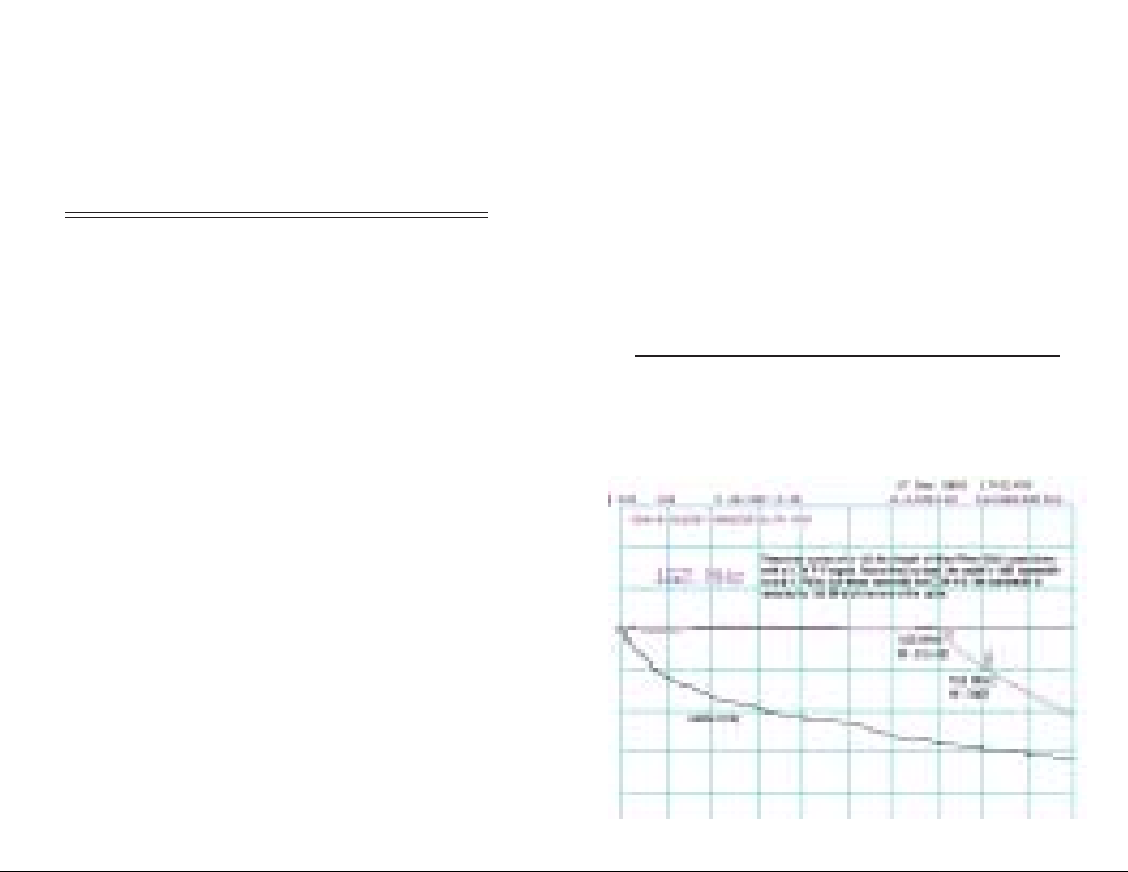
Bandwidth:
Supports up to QXGA (2048 X 1536 @ 60 Hz)
This performance data is based on the CDA-4/6 plus
the specifi ed length of WP8255 (West Penn) cable with
a full amplitude (0.7V p-p) signal applied.
150' cable 162 MHz (-3dB) 0-143 MHz 0.5 dB fl atness
a small amplitude (0.2V p-p) signal applied.
150' cable 305 MHz (-3dB) 0-256 MHz 0.5 dB fl atness
Level (nominal): Unity / User adjustable via potientiometer
Impedance: 75 ohms
Design Cable: West Penn WP8255 or equal
Video Output
Number/type: 4 (CDA-4), 6 (CDA-6), RGBHV, RGBS, RGsB, RsGsBs,
component video, S-video,
Connectors: All female HD - 15
Bandwidth: 375 MHz @ -3 dB (typical) fully loaded with a 0.7V
p-p input signal
Flatness: 0.5 dB to 297 MHz (typical) fully loaded with a 0.7V p-p
input signal
Gain: Unity (buffered)
Impedance: 75 Ohms
Differential Gain 0.04%
Differential Phase 0.15 degrees
The all new CDA - 4 and 6 are ultra high resolution, ultra high bandwidth 1 x 4
and 1 x 6 computer distribution amplifi ers suitable for applications requiring the
highest possible video quality. The output channels on each unit
have cable equalization permiting long cable runs while maintaining excellent
signal integrity for even the highest video resolutions.
Not only do these two units have over 375 MHz of bandwidth but they also have
the FSR computer compatible sychronizing circuitry to ensure a rock stable
video image at any resolution and signal level.
The outputs are equalized to maintain excellent signal integrity for all video
resolutions. Cable runs of up to 150 feet are possible with 162 MHz of full
amplitude bandwidth and 0.5 dB peaking. Peaking remains below 0.5 dB even
at 0.2V p-p input level.
Channel-channel matching (red vs green/red vs blue) response is extremely
fl at. About 0.25 dB out to 320MHz
It will restore the bandwidth of 150' of the design cable to 162 MHz, with a
0.5 dB fl atness to 143MHz at full 0.7V p-p amplitude. At 0.2V p-p, these
fi gure become 305MHz and 256MHz respectively
This means that the signal you feed into the CDA-4 or CDA-6 will arrive at
the far end of the cable with an almost immeasurable amount of loss and no
distortion due to peaking effects.
FEATURES
•Minimum 350 MHz of bandwidth fully loaded
• +/- 0.5 dB fl atness to 270 MHz
• Computer compatible sychronizing circuitry
• HD-15 female connectors for the input and each output
• Full cable equalization control for the output channels
• Compatible with all computer standards
• UL amd CSA approved external power source (wall plug-in) with special
locking connector
APPLICATIONS
• Boardrooms
• Houses of Worship
• Control Rooms
• Classrooms
• Staging and Rental
Page 4

INSTALLATION and OPERATION
Do not connect the power line cord until all the video connections are completed.
Mount the unit in the equipment rack, using the supplied rack
mounting.
Connect all the video cables per the diagram. Please read the note
concerning output 2 on the application drawing.
Connect the power cord. Note the robust locking power connector.
Adjust the cable equalization, with the variable control for minimum distortion using an appropriate test signal or full motion
video.
Perform the fi nal operational check.
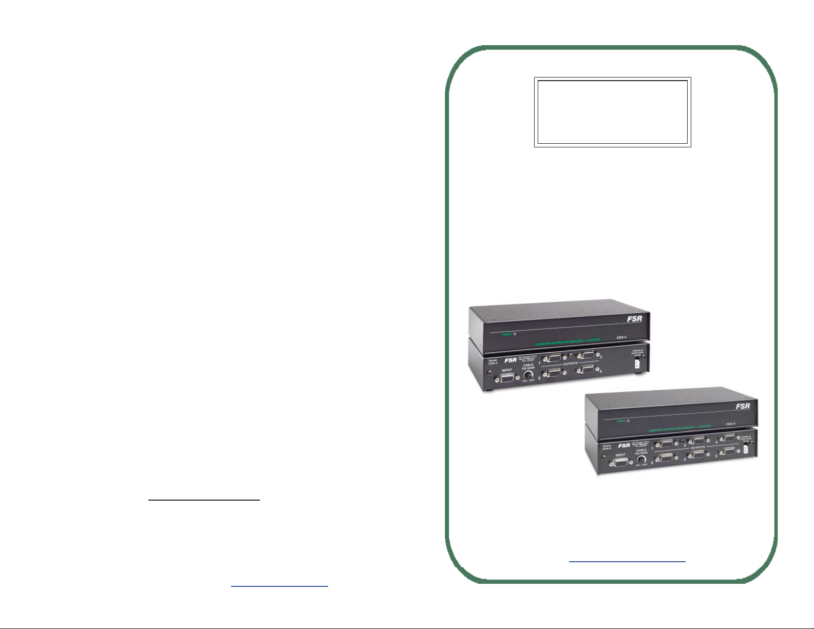
FRONT AND REAR PHOTOS OF THE EQUIPMENT
TYPICAL APPLICATION
NOTE:
USE ONLY AN HD-15
TO HD-15 CABLE ON
OUTPUT 2 TO ENSURE
THAT ID BITS ARE
PASSED THROUGH TO
THE COMPUTER
 Loading...