

Page 1
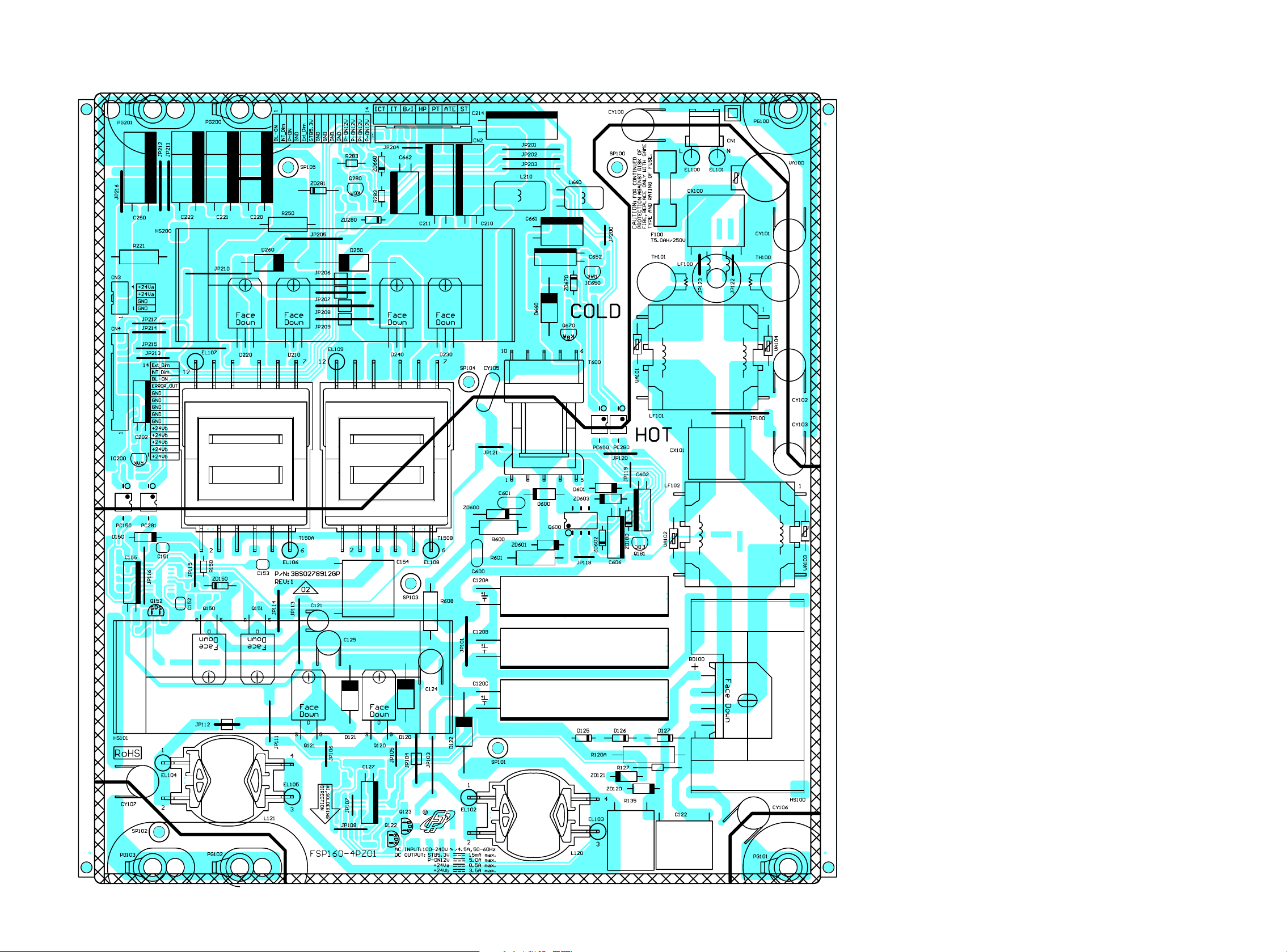
Power Supply CBA Top View
NOTE:
The voltage for parts in hot circuit is measured using
hot GND as a common terminal.
Because a hot chassis ground is present in the power supply
circuit, an isolation transformer must be used when repairing.
Also, in order to have the ability to increase the input slowly,
when troubleshooting this type of power supply circuit,
a variable isolation transformer is required.
CAUTION !
For continued protection against fire hazard,
replace only with the same type fuse.
CAUTION !
Fixed voltage (or Auto voltage selectable) power supply circuit is used in this unit.
If Main Fuse (F100) is blown , check to see that all components in the power supply
circuit are not defective before you connect the AC plug to the AC power supply.
Otherwise it may cause some components in the power supply circuit to fail.
10-17
UPBPSPFSP004
Page 2
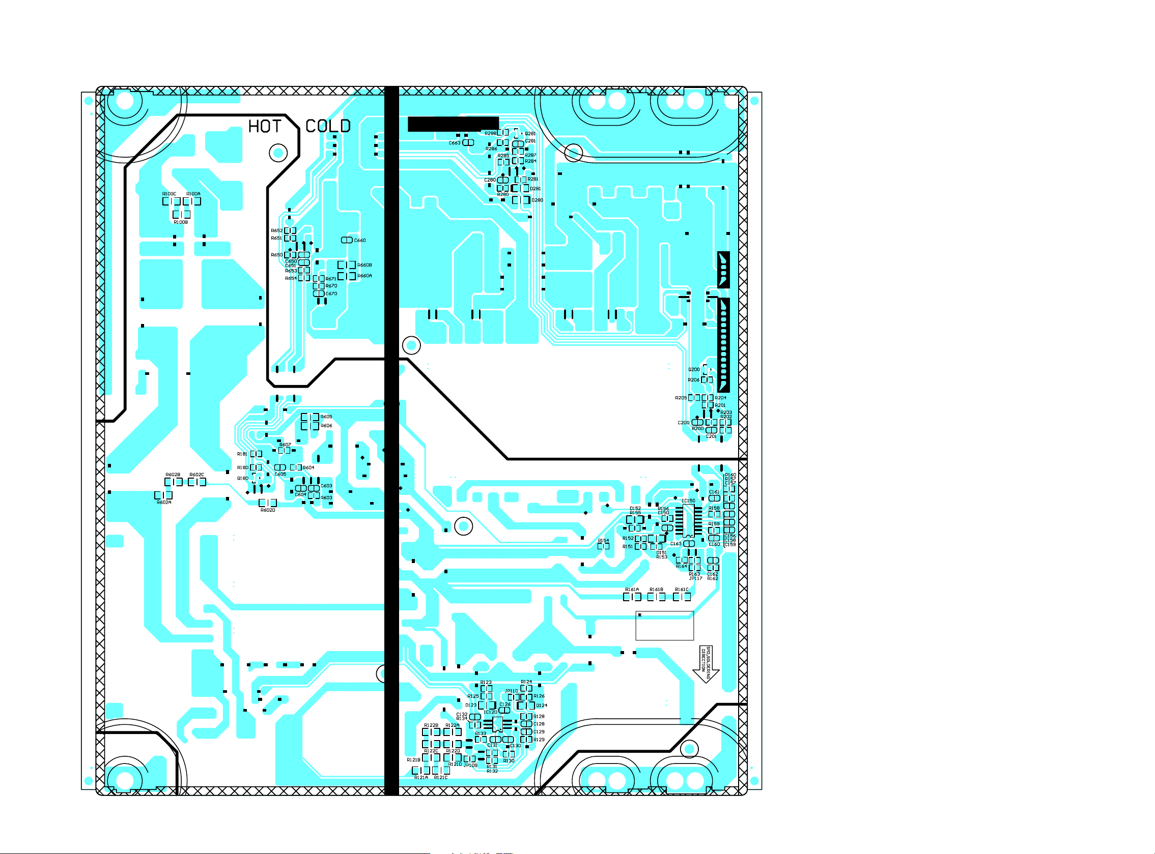
Power Supply CBA Bottom View
NOTE:
The voltage for parts in hot circuit is measured using
hot GND as a common terminal.
Because a hot chassis ground is present in the power supply
circuit, an isolation transformer must be used when repairing.
Also, in order to have the ability to increase the input slowly,
when troubleshooting this type of power supply circuit,
a variable isolation transformer is required.
CAUTION !
For continued protection against fire hazard,
replace only with the same type fuse.
CAUTION !
Fixed voltage (or Auto voltage selectable) power supply circuit is used in this unit.
If Main Fuse (F100) is blown , check to see that all components in the power supply
circuit are not defective before you connect the AC plug to the AC power supply.
Otherwise it may cause some components in the power supply circuit to fail.
10-18
UPBPSPFSP004
Page 3

Power Supply Block Diagram
NOTE:
The voltage for parts in hot circuit is measured using
hot GND as a common terminal.
TO SYSTEM
CONTROL
BLOCK
PROTECT1
DIAGRAM
AL+3.3V
+6V REG.
IC2603
F2603
AMP+24V
P-ON+12V
JACK CBA
+3.3V REG.
IC2602
F2602
P-ON+5V
+5V REG.
IC2605
P-ON+6V20,21
CN2105
TO DIGITAL
MAIN CBA
UNIT
P-ON+3.3V15-17
P-ON+12V26-29
CN3701
AL+5.3V9,10
AL+3.3V11
TO SYSTEM
CONTROL
BLOCK DIAGRAM
CN2602
BACKLIGHT-SW5BACKLIGHT-ADJ(PWM)12BACKLIGHT-SW14BACKLIGHT-ADJ(PWM)
P-ON-H2
1
3
CN2
CN4
TO LCD MODULE
ASSEMBLY
LED+24V1-5
CN4
3,4
AMP+24V3,4
CN3 CN2603
Q670
6
7
T600
1
4
5
CAUTION !
Fixed voltage (or Auto voltage selectable) power supply circuit is used in this unit.
If Main Fuse (F100) is blown , check to see that all components in the power supply
circuit are not defective before you connect the AC plug to the AC power supply.
Otherwise it may cause some components in the power supply circuit to fail.
6
CN2602
11-14
P-ON+12V
AL+5.3V6
11-14
CN2
Q281
REG.
SHUNT
9
8
10
PC650
3
Q123
FEED
Q121
14
(FEED BACK)
Q120
BACK
3 2
IC650
Q122
(ISOLATOR)
PC280
SWITCHING
Q180, Q181
14
IC200
14
(FEED BACK)
3 2
Q280
REG.
SHUNT
7
9
T150B
3 2
SWITCHING
Q150
11
3
SWITCHING
Q151
8
12
5
Q152
7
9
10
T150A
8
11
12
5
3
10
14
PC150
(FEED BACK)
PC281
3 2
HOT COLD
F100
CAUTION !
For continued protection against fire hazard,
replace only with the same type fuse.
HOT CIRCUIT. BE CAREFUL.
AC601
AC CORD
BRIDGE
RECTIFIER
BD100
LINE
FILTER
LF100-LF102
T5AH
/250V
L
CN1
N
SW601
7
3
FB
OUT1
IC120
(SWITCHING CONTROL)
5
OUT2
2
VIN
(SWITCHING)
Q600
7
8
DRIVE
DRIVE
4
FB
9-5
5
VCC
16
11
VGL
VGH
HIGH-VOLTAGE
RESONANT CONTROL
IC150
2
VCC
1
VSEN
3
7
6
FB
RC
OC
POWER SUPPLY CBA UNIT
A13P0BLP
Page 4

Power Supply Schematic Diagram
CAUTION !
For continued protection against fire hazard,
replace only with the same type fuse.
4
3
2
1
AC601
AC CORD
AC
INLET
CAUTION !
Fixed voltage (or Auto voltage selectable) power supply circuit is used in this unit.
If Main Fuse (F100) is blown , check to see that all components in the power supply
circuit are not defective before you connect the AC plug to the AC power supply.
Otherwise it may cause some components in the power supply circuit to fail.
HOT CIRCUIT. BE CAREFUL.
SW601
CN1
VA101
F100
T5AH/250V
L
N
VA100
TVT14471
CY101
330P
/250V
R130
36K
C131
0.1
CY100
330P
/250V
C130
0.22
R128
33K
CX100
0.22
/275V
CY102
330P
/250V
C128
1000P
C129
1000P
LF100
OTC28A29
R100A
680K
R100B
680K
R100C
680K
CY103
330P
/250V
Q152
AP01L60P
(SWITCHING)
R163
100K
L120
8TI0072701GP
L121
8TI0072701GP
R121A
1M
R121B
1M
R121C
1M
R121D
680K
Q122
AP01L60P
D
(SWITCHING)
G
S
R129
33K
R122A
1M
R122B
1M
R122C
1M
R122D
680K
D
S
R132
100K
IC120
SSC2101S
SWITCHING
CONTROL
1
COMP
2
VIN
3
FB
45
VCC
C127
C126
22/50V
0.1
TH101
LF101
2R55A
8LE0045802GP
TH100
2R55A
R162
20K
G
C120A
68/450V
Q121
2SK4111
D
(SWITCHING)
G
S
Q123
AP01L60P
(FEED BACK)
G
R134
100K
R131
20K
8
IS
7
OUT1
6
GND
OUT2
300V
CX101
0.22
/275V
VA104
300V
R161C1MR161B1MR161A
1M
D
S
C163
0.01
C120B
C120C
68/450V
68/450V
D122
OPEN
C124
100P/1KV
D120
RY2A
C125
100P/1KV
D121
RY2A
Q120
2SK4111
D
(SWITCHING)
G
S
R124
10K
R133
20K
R127
100
C132
680P
R164
22K
C121
OPEN
R12320R125
10K
D124
R126
4148
20
R120A
0.06/3W
VA102
OPEN
LF102
8LE0045802GP
VA103
OPEN
D123
4148
D127
4148
D126
4148
D125
4148
BD100
GBU406
C162
0.1
C158
1
C122
0.68
/450V
C155
10/50V
C156
680P
R159
10K
C159
1
R135
0.47/5W
R158
470
C157
1000P
R602A
2.2M
ZD120
1ZB220-Y
ZD121
1ZB220-Y
IC150
SSC9512
HIGH-VOLTAGE
RESONANT
CONTROL
1
VSEN
VCC
FB
4
GND
5
SS
6
OC
7 12
RC
8
9
RV COM
R157
C161
100
0.22
C160
0.033
R602C
R602B
2.2M
2.2M
ZD601
R601
1N4734A
3/2W
C603
R603
0.22
1M
R604
4.7M
NOTE:
The voltage for parts in hot circuit is measured using
hot GND as a common terminal.
CY106
680P/250V
T150B
POWER TRANS
3
Q150
D151
1N4148
C150
0.22
ZD150
OPEN
18
NU
172
NU
163
VGH
15
VS
14
VB
13
NU
C151
10P
NU
/1KV
11
VGLREG
10
D15010R150
1N4937
R602D
2.2M
Q600
STR-A6069
(SWITCHING)
1
2
3
45
ZD60322C606
1N4749A
ZD602
OPEN
Q180
PMBT2222A
(SWITCHING)
S/OCP
D/ST
BR
D/ST
GND
NU
FB
VCC
C604
2200P
Q181
PMBT2222A
(SWITCHING)
ZD180
TZX16B
R180
510
8
7
6
R153
47
D152
1N4148
R155
51
R156
10
C600
OPEN
C605
0.1
R608
1/2W
2SK4110
(SWITCHING)
R152
10
Q151
2SK4110
(SWITCHING)
R607
100
G
R151
10K
G
R154
10K
C153
220P/1KV
R160
560
ZD600
P6KE150A
D600
UF1007
D601
1N4937
C602
22
R181
20K
D
S
C152
220P
D
/1KV
5
S
R600
OPEN
R605
10
R606
10
C154
0.033
/1KV
C601
OPEN
T150A
POWER TRANS
3
5
PC150
PS256
(FEEDBACK)
4
32
T600
POWER TRANS
1
4
5
3
PC650
PS256
(FEEDBACK)
4
32
PC281
PS256
(FEEDBACK)
4
32
PC280
PS256
(ISOLATOR)
4
32
CY105
680P/250V
POWER SUPPLY CBA UNIT
TO JACK CBA
CN3
CN2603
OPENCY107
11
12
10
11
12
10
10
D250
SB5100
D240
MBR10100
9
D230
SBR20U40CT
7
8
D260
SB5100
D220
MBR10100
9
D210
SBR20U40CT
7
8
R206
OPEN
C202
R282
1K
R285
2K
Q670
BT169D
D660
SB240
R660A
20
R660B
20
R654
100
OPEN
C660
470P
Q280
BT169D
C670
0.1
1
6
7
8
9
1
R653
1K
C652
2.2
1
1
COLDHOT
Q200
OPEN
C661
220/25V
R284
1K
R671
10
R670
510
L660
8LR0062201GP
R283
100
C280
0.1
C250
470/35V
C220
470/35V
C210
470/25V
ZD670
NXP6V2B
R280
510
R202
1K
R286
2K
R250
1K/2W
C221
470/35V
C211
470/25V
R203
3K
R2001C200
1K
IC200
KIA431A
SHUNT
REG.
R281
100
C222
470/35V
C201
OPEN
C662
220/10V
C651
OPEN
C650
0.22
IC650
TL431
SHUNT
REG.
Q281
2N7002
D
(SWITCHING)
G
S
R201
1.3K
ZD660
OPEN
R650
27K
L210
R6*15
R204
33.2K
R205
7.87K
C281
0.1
C663
0.1
R652
10K
R651
9.1K
R221
1K/2W
C214
470/25V
R287
100K
ZD281
NXP30B
D281
1N4148
R288
20K
JP213
OPEN
ZD280
NXP15B
D280
1N4148
JP217
1 GND
2 GND
3 AMP+24V
4 AMP+24V
TO LCD MODULE
ASSEMBLY
CN4
1 LED+24V
2 LED+24V
3 LED+24V
4 LED+24V
5 LED+24V
6 GND
7 GND
8 GND
9 GND
10 GND
11 NU
12 BACKLIGHT-SW
13 NU
14 BACKLIGHT-ADJ(PWM)
TO JACK CBA
CN2602
CN2
14 P-ON+12V
13 P-ON+12V
12 P-ON+12V
11 P-ON+12V
10 GND
9 GND
8 GND
7 GND
6 AL+5.3V
5 BACKLIGHT-ADJ(PWM)
4 GND
3 P-ON-H2
2 NU
1 BACKLIGHT-SW
A EC
B
10-7
FD
A13P0SCP
 Loading...