

Page 1

13 Oct 2017
A320Neo-1UI-ISS-IUG_Rev0
A320
Instructor Operating Station
Instructor User Guide
Page 2

Page 3

Instructor User Guide
Safety Precautions
13 Oct 2017
Page i
Safety Precautions
Safety Precautions
The following general safety notices supplement the specific warnings and cautions appearing
elsewhere in this manual. These are recommended precautions that must be understood and
applied during operation and maintenance of the equipment covered herein. Should situations
arise that are not covered by safety precautions given, consult the proper local authority.
1. Under no circumstances should a person operate or maintain this equipment without the
immediate presence or assistance of another person capable of rendering aid.
2. Personnel working with or near high voltages must be familiar with modern methods of
resuscitation. In the event of electrical shock, always:
a) Remove power.
b) Administer first aid treatment.
c) Summon assistance.
3. In the event of fire, carry out the procedures provided in your local fire code.
4. All operation and maintenance personnel should be familiar with the location and
function of the emergency shutdown switches. They should also be familiar with the
emergency procedures needed to remove power from damaged equipment.
5. The simulator has voltages that are dangerous and may be fatal if contacted by operation
or maintenance personnel.
6. Do not energize equipment unless safety grounds have been established; failure to do so
may result in electrical shock to the operator.
7. Before starting the motion system, ensure that the area around the simulator envelope is
clear of personnel and that all loose objects are secured.
8. If, at any time, a safety hazard is detected, it is the responsibility of the individual to
report the hazard to ensure it is corrected.
9. All personnel in the flight compartment are to be fastened with seat belts.
10. Do not adjust the seat(s) when the motion system is on.
Page 4

Page 5

List of Effective Pages
13 Oct 2017
Page iii
List of Effective Pages
Subject/
Page
Title
Nos.
Date
Instructor User Guide
Safety Precautions
i
13 Oct 2017
List of Effective Pages (this leaf)
iii
13 Oct 2017
Table of Contents
v-xxiii
13 Oct 2017
List of Figures
xxv-xxix
13 Oct 2017
List of Tables
xxxi
13 Oct 2017
1 Introduction
1
13 Oct 2017
2 On-board Instructor Station Configuration
3
13 Oct 2017
3 IOS Software Interface
5-15
13 Oct 2017
4 Control Board Workspace
17-19
13 Oct 2017
5 LESSON PLAN Tab
21-24
13 Oct 2017
6 DOCS Tab
25-26
13 Oct 2017
7 CURRENT CONDITIONS Tab
27-46
13 Oct 2017
8 AIRCRAFT Tab
47-93
13 Oct 2017
9 REFERENCE AIRPORT Tab
95-156
13 Oct 2017
10 INSTRUCTOR STATION Sliding Panel
157-161
13 Oct 2017
11 Control Board Footer
163-202
13 Oct 2017
12 Maintenance Pages
203
13 Oct 2017
13 INSTRUMENT REPEATER Workspace
205-206
13 Oct 2017
14 Lesson Plan Profile Workspace
207-210
13 Oct 2017
15 Map Workspace
211-236
13 Oct 2017
16 Advanced
237-295
13 Oct 2017
Instructor User Guide
List of Effective Pages
Page 6

Page 7

Instructor User Guide
Table of Contents
13 Oct 2017
Page v
Table of Contents
Table of Contents
1. Introduction .............................................................................................................. 1
2. On-board Instructor Station Configuration............................................................ 3
3. IOS Software Interface ............................................................................................. 5
3.1 IOS Workspaces ........................................................................................ 5
3.2 User Interface (UI) Controls ....................................................................... 6
3.2.1 Sliding Panel ........................................................................... 6
3.2.2 Text Field ................................................................................ 7
3.2.3 Read Only Field ...................................................................... 7
3.2.4 Indicators ................................................................................ 7
3.2.5 Button ...................................................................................... 7
3.2.6 Roll-up menu ........................................................................... 7
3.2.7 Wheel Picker ........................................................................... 7
3.3 Selecting Parameters and Entering Data ................................................... 8
3.3.1 Tapping on a Parameter Text Field ......................................... 8
3.3.2 Quick Access Buttons ............................................................. 8
3.3.3 Dropdown Buttons................................................................... 9
3.3.4 Selection Buttons .................................................................... 9
3.3.4.1 Toggle Normal Button ................................................ 9
3.3.4.2 Toggle Fail Button...................................................... 9
3.3.4.3 Action Button ........................................................... 10
3.3.5 Expandable Buttons .............................................................. 10
3.3.6 Radio Buttons ....................................................................... 11
3.3.7 Checkbox .............................................................................. 11
3.3.8 Sliders ................................................................................... 11
3.3.9 Wheel Picker ......................................................................... 12
3.3.10 Keypad .................................................................................. 14
3.3.11 Interactive Graphs ................................................................. 15
4. Control Board Workspace ..................................................................................... 17
4.1 Tabs and Interface Elements ................................................................... 18
5. LESSON PLAN Tab ................................................................................................ 21
5.1 Lesson Outline Section ............................................................................ 23
5.2 Lesson Step Details Section .................................................................... 23
5.3 Lesson Training Phases ........................................................................... 23
5.4 Lesson Steps ........................................................................................... 23
5.5 LESSON PLAN Tab Buttons .................................................................... 24
5.5.1 Autorun ................................................................................. 24
5.5.2 Step-by-step .......................................................................... 24
5.5.3 Go to Current ........................................................................ 24
5.5.4 Skip Condition ....................................................................... 24
5.5.5 Execute ................................................................................. 24
5.5.6 End Lesson ........................................................................... 24
Page 8

A320 Neo Instructor Operating Station
Table of Contents
13 Oct 2017
Page vi
Instructor User Guide
6. DOCS Tab ............................................................................................................... 25
6.1 Thumbnail View ........................................................................................ 25
6.2 List View ................................................................................................... 25
6.3 Scroll Up and Down ................................................................................. 25
6.4 Search Function ....................................................................................... 25
6.5 View Expansion ........................................................................................ 25
6.6 Zoom ........................................................................................................ 25
7. CURRENT CONDITIONS Tab ................................................................................ 27
7.1 Parameter Input Text Fields ..................................................................... 28
7.1.1 Clouds and Visibility Section ................................ ................. 28
7.1.2 ASL ....................................................................................... 28
7.1.3 IAS ........................................................................................ 28
7.1.4 Mach ..................................................................................... 28
7.1.5 Heading ................................................................................. 28
7.1.6 Icing Conditions .................................................................... 29
7.1.7 Turbulence ............................................................................ 29
7.1.8 A/C Wind ............................................................................... 29
7.1.9 A/C OAT ................................................................................ 29
7.1.10 A/C ISA Dev .......................................................................... 29
7.2 CLOUDS AT AIRCRAFT Sliding Panel .................................................... 29
7.2.1 Visibility Section .................................................................... 31
7.2.2 Cloud Level Section .............................................................. 31
7.2.2.1 High Level Cloud ..................................................... 31
7.2.2.2 Medium Level Cloud ................................................ 31
7.2.2.3 Low Level Cloud ...................................................... 32
7.2.2.4 Medium Level Cloud Thickness ............................... 32
7.2.2.5 Low Level Cloud Thickness ..................................... 32
7.2.3 Fog Section ........................................................................... 32
7.2.3.1 No Fog ..................................................................... 32
7.2.3.2 Patchy Fog and Thickness ...................................... 33
7.2.3.3 Solid Fog and Thickness ......................................... 33
7.2.3.4 RVR Min/Max .......................................................... 33
7.2.4 Weather Presets Section ...................................................... 33
7.2.4.1 CAVOK .................................................................... 33
7.2.4.2 1000/5km ................................................................. 33
7.2.4.3 800/2km ................................................................... 34
7.2.4.4 CAT I ....................................................................... 34
7.2.4.5 CAT II ...................................................................... 34
7.2.4.6 CAT IIIA ................................................................ ... 34
7.2.4.7 CAT IIIB ................................................................ ... 34
7.2.4.8 CAT IIIC ................................................................... 34
7.2.4.9 0/0 ............................................................................ 34
7.2.4.10 MIN T/O RVR .......................................................... 34
7.3 SLEW Sliding Panel ................................................................................. 34
7.3.1 ALTITUDE / SPEED Tab ...................................................... 35
Page 9

Instructor User Guide
Table of Contents
13 Oct 2017
Page vii
Table of Contents
7.3.1.1 Altitude ..................................................................... 35
7.3.1.2 Altitude Slider .......................................................... 35
7.3.1.3 Airspeed .................................................................. 35
7.3.1.4 Airspeed Slider ........................................................ 36
7.3.1.5 Mach ........................................................................ 36
7.3.1.6 Graph ....................................................................... 36
7.3.2 HEADING / POSITION Tab .................................................. 36
7.3.2.1 Heading ................................................................... 36
7.3.2.2 Heading Slew Increase (+) / Decrease (-)................ 36
7.3.2.3 Forward ................................................................... 37
7.3.2.4 Back ......................................................................... 37
7.3.2.5 Left ........................................................................... 37
7.3.2.6 Right ........................................................................ 37
7.3.2.7 Lat / Long ................................................................. 37
7.3.2.8 Hook (Optional)........................................................ 37
7.3.2.9 Position Slew Rate Slider ........................................ 37
7.3.3 Slew ...................................................................................... 37
7.3.4 Discard .................................................................................. 37
7.4 ICING Sliding Panel ................................................................................. 38
7.4.1 Icing Conditions Exist ............................................................ 38
7.4.2 Light ...................................................................................... 38
7.4.3 Moderate ............................................................................... 38
7.4.4 Severe ................................................................................... 39
7.4.5 Remove Ice ........................................................................... 39
7.4.6 ICE ACCUMULATION Section ............................................. 39
7.4.6.1 Weight ..................................................................... 39
7.4.6.2 % ............................................................................. 39
7.5 TURBULENCE Sliding Panel ................................................................... 40
7.5.1 CLEAR AIR Turbulence ........................................................ 41
7.5.1.1 CLEAR AIR - Light ................................................... 41
7.5.1.2 CLEAR AIR - Moderate ........................................... 41
7.5.1.3 CLEAR AIR - Severe ............................................... 41
7.5.1.4 Intensity ................................................................... 41
7.5.2 THUNDERSTORM Turbulence ............................................. 41
7.5.2.1 THUNDERSTORM - Light ....................................... 42
7.5.2.2 THUNDERSTORM - Moderate ................................ 42
7.5.2.3 THUNDERSTORM - Severe .................................... 42
7.5.2.4 Intensity ................................................................... 42
7.5.3 LOW LEVEL Turbulence ....................................................... 42
7.5.3.1 LOW LEVEL Turbulence - Light............................... 42
7.5.3.2 LOW LEVEL Turbulence – Moderate ...................... 42
7.5.3.3 LOW LEVEL Turbulence – Severe .......................... 43
7.5.3.4 Intensity ................................................................... 43
7.5.4 Clear All ................................................................................ 43
7.5.5 Turbulence Types Priority ..................................................... 43
7.6 A/C Wind Keypad ..................................................................................... 44
Page 10

A320 Neo Instructor Operating Station
Table of Contents
13 Oct 2017
Page viii
Instructor User Guide
7.7 A/C OAT Keypad ...................................................................................... 45
7.8 A/C ISA Dev Keypad ................................................................................ 46
8. AIRCRAFT Tab ....................................................................................................... 47
8.1 Parameter Input Text Fields ..................................................................... 48
8.1.1 GW ........................................................................................ 48
8.1.2 GW CG ................................................................................. 48
8.1.3 ZFW ...................................................................................... 49
8.1.4 ZFW CG ................................................................................ 49
8.1.5 Fuel ....................................................................................... 49
8.2 GW Keypad .............................................................................................. 50
8.3 GW CG Keypad ....................................................................................... 50
8.4 ZFW Keypad ............................................................................................ 51
8.5 ZFW CG Keypad ...................................................................................... 51
8.6 Fuel Keypad ............................................................................................. 52
8.7 Quick Access Buttons .............................................................................. 52
8.7.1 DL ......................................................................................... 52
8.7.2 UL ......................................................................................... 52
8.7.3 VHF ....................................................................................... 53
8.7.4 Weight &CG ................................ ................................ .......... 53
8.7.5 Services & Doors .................................................................. 53
8.7.6 Malfunctions .......................................................................... 53
8.7.7 Circuit Breakers..................................................................... 53
8.7.8 Fail Summary ........................................................................ 53
8.8 DATALINK (DL/UL) Sliding Panel ............................................................ 54
8.8.1 LOG Tab ............................................................................... 55
8.8.2 NEW UPLINK Tab ................................................................. 55
8.8.2.1 GROUPS Section .................................................... 55
8.8.2.2 SCENARIOS Section ............................................... 55
8.8.2.3 SCENARIOS (Uplink Messages) Section ................ 55
8.8.2.3.1 Add Button ........................................................... 55
8.8.2.4 Message Editor Section ........................................... 56
8.8.2.4.1 Remove ............................................................... 56
8.8.2.4.2 ▲ and ▼ Buttons................................................. 56
8.8.3 CONNECTIVITY CONTROL Tab .......................................... 57
8.8.3.1 ATC Section ............................................................ 58
8.8.3.1.1 Read-Only Fields ................................................. 58
8.8.3.1.2 Radio Buttons ...................................................... 58
8.8.3.1.3 Disconnect ........................................................... 59
8.8.3.2 ADS Section ............................................................ 59
8.8.3.2.1 Read-Only Fields ................................................. 59
8.8.3.2.2 List of ADS Center IDs ......................................... 60
8.8.3.3 GROUND Section .................................................... 60
8.8.3.3.1 VHF Ground FAULT ............................................ 60
8.8.3.3.2 HF Ground FAULT ............................................... 60
8.8.3.3.3 SATCOM/GES FAULT......................................... 60
Page 11

Instructor User Guide
Table of Contents
13 Oct 2017
Page ix
Table of Contents
8.9 COMMUNICATIONS Sliding Panel .......................................................... 61
8.9.1 VOLUME Tab ........................................................................ 62
8.9.2 RADIO Tab ........................................................................... 62
8.9.3 INTERCOM Tab .................................................................... 63
8.9.4 NAVIGATION Tab ................................................................. 63
8.9.4.1 Receive .................................................................... 64
8.9.5 SPECIAL FEATURES Tab .................................................... 64
8.9.5.1 Pilot Private ............................................................. 64
8.9.5.2 Copilot Private ......................................................... 64
8.9.5.3 Pilot Monitoring ........................................................ 64
8.9.5.4 Copilot Monitor ........................................................ 64
8.9.5.5 Emergency Call ....................................................... 64
8.9.5.6 MECH Call ............................................................... 64
8.9.5.7 ATT Call ................................................................... 65
8.9.5.8 EVAC ....................................................................... 65
8.9.5.9 Mask ........................................................................ 65
8.9.5.10 Hardware ACP ......................................................... 65
8.9.5.11 VHF LOS OVRD ...................................................... 65
8.10 WEIGHT & BALANCE Sliding Panel ........................................................ 66
8.10.1 QUICKSETS Tab .................................................................. 67
8.10.1.1 Light Weight ............................................................. 67
8.10.1.2 Medium Weight ........................................................ 67
8.10.1.3 Heavy Weight .......................................................... 67
8.10.2 PERFORMANCE DATA Tab ................................................ 67
8.10.2.1 Stab Trim ................................................................. 67
8.10.2.2 Flaps ........................................................................ 67
8.10.2.3 V1 ............................................................................ 67
8.10.2.4 VR ............................................................................ 67
8.10.2.5 V2 ............................................................................ 67
8.10.2.6 VREF ....................................................................... 67
8.10.3 WEIGHT & CG Tab ............................................................... 68
8.10.3.1 ZFW ......................................................................... 69
8.10.3.2 Fuel .......................................................................... 69
8.10.3.3 GW .......................................................................... 70
8.10.3.4 GW CG .................................................................... 70
8.10.3.5 ZFW CG .................................................................. 71
8.10.3.6 Center of Gravity Limits Graph ................................ 71
8.10.3.7 Left Outer Fuel Tank ................................................ 71
8.10.3.8 Left Inner Fuel Tank ................................................. 72
8.10.3.9 Right Outer Fuel Tank ............................................. 72
8.10.3.10 Right Inner Fuel Tank ......................................... 73
8.10.3.11 Center Fuel Tank ................................................ 73
8.10.3.12 Fuel Balance ....................................................... 74
8.10.3.13 Fuel Freeze ......................................................... 74
8.10.3.14 Activate ............................................................... 74
8.10.3.15 Cancel................................................................. 74
Page 12

A320 Neo Instructor Operating Station
Table of Contents
13 Oct 2017
Page x
Instructor User Guide
8.11 SERVICES & DOORS Sliding Panel ........................................................ 74
8.11.1 SERVICES Tab ..................................................................... 75
8.11.1.1 Nav Fast Align ......................................................... 76
8.11.1.2 Engine Quick Start ................................................... 76
8.11.1.3 Engine Stagger ........................................................ 76
8.11.1.4 External Air .............................................................. 76
8.11.1.5 Ground Power AC.................................................... 76
8.11.1.6 A/C on Chocks ......................................................... 77
8.11.1.7 A/C on Jacks ........................................................... 77
8.11.1.8 APU Quick Start....................................................... 77
8.11.2 DOORS Tab .......................................................................... 78
8.11.2.1 Aircraft Access Door Buttons ................................... 79
8.11.2.1.1 Close All Doors .................................................. 79
8.11.2.1.2 Avionic Doors ..................................................... 79
8.11.2.1.3 Cabin (Forward Left Side) .................................. 79
8.11.2.1.4 Cabin (Forward Right Side) ............................... 79
8.11.2.1.5 Cabin (Aft Left Side) .......................................... 79
8.11.2.1.6 Cabin (Aft Right Side) ........................................ 79
8.11.2.1.7 EMER Exit (Left Side) ........................................ 79
8.11.2.1.8 EMER Exit (Right Side)...................................... 80
8.11.2.1.9 FWD Cargo ................................ ........................ 80
8.11.2.1.10 AFT Cargo ....................................................... 80
8.11.2.1.11 Bulk Cargo ....................................................... 80
8.11.2.2 SLIDES Section ....................................................... 80
8.11.2.3 FLIGHT DECK ACCESS Section ............................ 80
8.11.2.3.1 Door ................................ ................................ ... 80
8.11.2.3.2 Routine Request ................................................ 81
8.11.2.3.3 Emergency Request .......................................... 81
8.11.2.3.4 System Reset .................................................... 81
8.11.2.4 CABIN READY Section ........................................... 81
8.12 MALFUNCTIONS Sliding Panel ............................................................... 82
8.12.1 Status Section ....................................................................... 83
8.12.2 ATA CHAPTER Tab .............................................................. 83
8.12.3 ALPHABETICAL Tab ............................................................ 83
8.12.4 PHASE OF FLIGHT Tab (Optional) ...................................... 84
8.12.5 Activating/Arming a Malfunction ............................................ 84
8.12.5.1 Activate .................................................................... 85
8.12.5.2 Clear ........................................................................ 85
8.12.5.3 Edit Value ................................................................ 85
8.12.5.4 Arm .......................................................................... 85
8.12.5.5 CAUSE & EFFECT Section ..................................... 85
8.12.6 ARMING CRITERIA Sliding Panel ........................................ 85
8.12.6.1 Arm .......................................................................... 85
8.13 CIRCUIT BREAKERS Sliding Panel ........................................................ 87
8.13.1 ATA CHAPTER Tab .............................................................. 88
Page 13

Instructor User Guide
Table of Contents
13 Oct 2017
Page xi
Table of Contents
8.13.2 ALPHABETICAL (A - Z) Tab ................................................. 88
8.13.3 CIRCUIT BREAKERS Tab .................................................... 89
8.13.3.1 HARDWARE CB ...................................................... 89
8.13.3.2 SOFTWARE CB ...................................................... 89
8.13.3.3 UNPOWERED Flag ................................................. 89
8.14 FAIL SUMMARY Sliding Panel ................................................................ 90
8.14.1 MALFUNCTIONS Tab ........................................................... 90
8.14.2 CIRCUIT BREAKERS Tab .................................................... 90
8.14.3 RADIO STATIONS Tab ......................................................... 91
8.15 MALFUNCTIONS Section ........................................................................ 93
8.15.1 Activate ................................................................................. 93
8.15.2 Clear ..................................................................................... 93
8.15.3 Clear All ................................................................................ 93
8.15.4 Tap to Add ............................................................................ 93
9. REFERENCE AIRPORT Tab .................................................................................. 95
9.1 Parameter Input Text Fields ..................................................................... 96
9.1.1 Airport ................................................................................... 96
9.1.2 Runway ................................................................................. 96
9.1.3 Time of the Day ..................................................................... 96
9.1.4 Surface Wind (Mag) .............................................................. 97
9.1.5 Visibility ................................................................................. 97
9.1.6 RVR ...................................................................................... 97
9.1.7 Precipitation ................................................................ .......... 97
9.1.8 Clouds ................................ ................................ ................... 98
9.1.9 Temperature ......................................................................... 98
9.1.10 ISA Dev ................................................................................. 98
9.1.11 QNH ...................................................................................... 98
9.1.12 Microburst/Windshear ........................................................... 98
9.1.13 Runway Condition ................................................................. 99
9.1.14 Interactive Airport Section ..................................................... 99
9.2 AIRPORT & REPOSITION Sliding Panel ............................................... 100
9.2.1 REFERENCE LOCATION Tab ........................................... 101
9.2.1.1 Reference Airport................................................... 101
9.2.1.2 Destination Airport ................................................. 101
9.2.1.3 Change Reference Button ..................................... 101
9.2.1.4 Change Destination Button .................................... 102
9.2.1.5 Auto Reference Location ....................................... 103
9.2.1.5.1 Auto Mode ......................................................... 103
9.2.1.5.2 Manual Mode ..................................................... 103
9.2.2 AIRPORT REPOSITION Tab .............................................. 103
9.2.2.1 HOLD / TAXI Section ............................................. 105
9.2.2.1.1 HOLD ................................................................. 105
9.2.2.1.2 TAXI ................................................................... 105
9.2.2.2 GATE / PARKING SPOT Section .......................... 105
9.2.2.2.1 Gate or Parking Spot Number ............................ 106
Page 14

A320 Neo Instructor Operating Station
Table of Contents
13 Oct 2017
Page xii
Instructor User Guide
9.2.2.3 Reposition Presets Section .................................... 106
9.2.2.3.1 Medium Airwork ................................................. 106
9.2.2.3.2 High Airwork ...................................................... 107
9.2.2.3.3 1NM, 3NM LT .................................................... 107
9.2.2.3.4 1NM, 3NM RT .................................................... 108
9.2.2.3.5 T/O ..................................................................... 108
9.2.2.3.6 3 NM Short Final ................................................ 109
9.2.2.3.7 6NM ................................................................... 109
9.2.2.3.8 8NM ................................................................... 110
9.2.2.3.9 12NM, 1 NM LT ................................................. 110
9.2.2.3.10 12NM ............................................................... 111
9.2.2.3.11 12NM, 1NM RT ................................................ 111
9.2.2.4 Runway Lighting Section ....................................... 111
9.2.2.4.1 Runway .............................................................. 111
9.2.2.4.2 Runway Lights ................................................... 112
9.2.2.4.3 Advanced Lighting ............................................. 112
9.2.2.4.4 RUNWAY LIGHTING Sliding Panel ................... 112
9.2.2.4.5 Localizer ............................................................ 115
9.2.2.4.6 Glideslope .......................................................... 115
9.2.3 GROUND OPERATIONS Tab ............................................ 115
9.2.3.1 Ground Operations ................................................ 116
9.2.3.1.1 Marshaller .......................................................... 116
9.2.3.2 Aircraft Pushbacks ................................................. 116
9.2.3.2.1 Tail Left .............................................................. 116
9.2.3.2.2 Straight .............................................................. 116
9.2.3.2.3 Tail Right ............................................................ 116
9.2.3.3 A/C on Chocks ....................................................... 117
9.2.3.4 RUNWAY CONDITION Section ............................. 117
9.2.3.4.1 Runway Condition .............................................. 117
9.2.3.5 VISUAL EFFECT Section ...................................... 117
9.2.3.5.1 Record Traffic .................................................... 117
9.2.3.5.2 RECORDED TRAFFIC Sliding Panel ................ 117
9.2.3.5.3 Scenario Traffic .................................................. 118
9.2.3.5.4 SCENARIO TRAFFIC Sliding Panel .................. 118
9.2.4 FMS QUICKSET Tab .......................................................... 119
9.2.4.1 FMS Save .............................................................. 119
9.2.4.2 FMS Recall ............................................................ 119
9.2.4.3 FMS Memory ......................................................... 119
9.2.5 FMS MEMORY SAVE/RECALL Sliding Panel .................... 119
9.2.5.1 MESSAGE Tab ...................................................... 120
9.2.5.1.1 Description ......................................................... 120
9.2.5.1.2 Password ........................................................... 120
9.2.5.1.3 Save .................................................................. 120
9.2.5.1.4 Recall ................................................................. 120
9.2.5.1.5 Cancel................................................................ 121
Page 15

Instructor User Guide
Table of Contents
13 Oct 2017
Page xiii
Table of Contents
9.2.5.1.6 Delete Selected ................................................. 121
9.2.5.1.7 Clear all Unprotected ......................................... 121
9.2.5.2 PASSWORD PROTECTED Tab............................ 121
9.2.5.3 UNPROTECTED Tab ............................................ 121
9.2.5.4 Saving a Password Protected Flight Plan .............. 121
9.2.5.5 Saving an Unprotected Flight Plan ........................ 121
9.2.5.6 Recalling a Flight Plan ........................................... 122
9.2.5.7 SIMSOFT CONTROLS Tab ................................... 122
9.2.5.7.1 Save .................................................................. 122
9.2.5.7.2 Recall ................................................................. 122
9.2.5.7.3 Inhibit Auto Recall .............................................. 122
9.2.6 Reposition Button ................................................................ 122
9.2.7 Discard Button .................................................................... 122
9.3 Time of the Day Keypad ......................................................................... 123
9.4 TIME OF DAY Sliding Panel .................................................................. 124
9.5 SURFACE WIND Sliding Panel .............................................................. 125
9.5.1 QUICK SELECTION Tab .................................................... 126
9.5.1.1 H10 ........................................................................ 126
9.5.1.2 H20 ........................................................................ 126
9.5.1.3 H30 ........................................................................ 126
9.5.1.4 T5 .......................................................................... 127
9.5.1.5 T10 ........................................................................ 127
9.5.1.6 T15 ........................................................................ 127
9.5.1.7 L10 ......................................................................... 127
9.5.1.8 L20 ......................................................................... 127
9.5.1.9 L38 ......................................................................... 127
9.5.1.10 R10 ........................................................................ 127
9.5.1.11 R20 ........................................................................ 127
9.5.1.12 R38 ........................................................................ 127
9.5.2 WIND COMPASS Tab ........................................................ 128
9.5.2.1 Runway Wind Components ................................... 129
9.5.2.2 Runway Up ............................................................ 129
9.5.2.3 FAA Gust Backing ................................................. 129
9.5.2.4 FAA Gust Veering .................................................. 129
9.5.3 Reference Airport ................................................................ 129
9.5.4 Wind .................................................................................... 129
9.5.5 Gusting to ............................................................................ 129
9.5.6 FAA Gust ............................................................................ 130
9.5.7 Calm Surface Wind ............................................................. 130
9.5.8 Calm All Winds .................................................................... 130
9.5.9 Activate ............................................................................... 130
9.5.10 Cancel ................................................................................. 130
9.6 Visibility Keypad ..................................................................................... 131
9.7 VISIBILITY / RVR Sliding Panel ............................................................. 132
9.7.1 Visibility ............................................................................... 132
9.7.2 FOG Tab ............................................................................. 132
Page 16

A320 Neo Instructor Operating Station
Table of Contents
13 Oct 2017
Page xiv
Instructor User Guide
9.7.2.1 None ...................................................................... 132
9.7.2.2 Patchy .................................................................... 132
9.7.2.3 Solid ....................................................................... 133
9.7.2.4 RVR Min/Max ........................................................ 133
9.7.2.5 RVR ....................................................................... 133
9.7.2.6 Fog Top ................................................................. 133
9.8 PRECIPITATION Sliding Panel .............................................................. 134
9.8.1 Light Rain ............................................................................ 135
9.8.2 Moderate Rain .................................................................... 135
9.8.3 Heavy Rain ......................................................................... 135
9.8.4 Snow ................................................................................... 136
9.8.5 Hail ...................................................................................... 136
9.8.6 EFFECT Tab ....................................................................... 136
9.8.6.1 Winter Scene ......................................................... 136
9.8.6.2 Blowing Snow ........................................................ 136
9.8.6.3 Blowing Sand ......................................................... 137
9.8.6.4 Lightning & Thunder .............................................. 137
9.9 CLOUDS Sliding Panel .......................................................................... 137
9.10 Ref Temp Keypad .................................................................................. 138
9.11 ISA Dev Keypad ................................................................ ..................... 139
9.12 QNH Keypad .......................................................................................... 140
9.13 WINDSHEAR & MICROBURST Sliding Panel ....................................... 141
9.13.1 MICROBURST Tab ............................................................. 142
9.13.1.1 Microburst Map ...................................................... 142
9.13.1.2 TAKEOFF PROFILE Section ................................. 142
9.13.1.2.1 New Orleans Accident ..................................... 142
9.13.1.2.2 Tucson in 1977 Denver in 1984 ....................... 143
9.13.1.3 LANDING PROFILE Section ................................. 143
9.13.1.3.1 1975 Kennedy Shear Accident ........................ 143
9.13.1.3.2 Headwind X Wind on Final Approach .............. 143
9.13.1.3.3 Wind Model from Aug 5 Jaws Data .................. 144
9.13.1.4 Description Button ................................................. 144
9.13.1.5 X Position .............................................................. 144
9.13.1.6 Y Position .............................................................. 145
9.13.1.7 Intensity Buttons .................................................... 145
9.13.1.7.1 Light ................................ ................................. 145
9.13.1.7.2 Moderate .......................................................... 145
9.13.1.7.3 Severe ............................................................. 145
9.13.1.8 Turbulence ............................................................. 145
9.13.1.9 Activate Microburst ................................................ 145
9.13.1.10 Clear Microburst ............................................... 145
9.13.2 PREDICTIVE WINDSHEAR Tab......................................... 146
9.13.2.1 TAKEOFF PROFILE Section ................................. 147
9.13.2.1.1 Tailwind Increasing to XX kt ............................. 147
Page 17

Instructor User Guide
Table of Contents
13 Oct 2017
Page xv
Table of Contents
9.13.2.1.2 Tailwind Increasing to XX kt, along with varying
updrafts, downdrafts, and crosswind ..................... 147
9.13.2.1.3 Tailwind Increasing to XX kt, along with downdraft
......................................................................... 147
9.13.2.2 LANDING PROFILE Section ................................. 147
9.13.2.2.1 Headwind Increasing to XX kt, switching to XXX
kts tailwind, along with varying updrafts, downdrafts
and crosswind ........................................................ 147
9.13.2.2.2 Tailwind Increasing to XX kt ............................. 148
9.13.2.3 X Position .............................................................. 148
9.13.2.4 Y Position .............................................................. 148
9.13.2.5 Intensity Buttons .................................................... 148
9.13.2.5.1 Light ................................ ................................. 148
9.13.2.5.2 Moderate .......................................................... 148
9.13.2.5.3 Severe ............................................................. 148
9.13.2.6 Turbulence ............................................................. 148
9.13.2.7 Activate Windshear ................................................ 148
9.13.2.8 Clear Windshear .................................................... 148
9.13.3 NON-PREDICTIVE WINDSHEAR Tab ............................... 149
9.13.3.1 TAKEOFF PROFILE Section ................................. 150
9.13.3.2 Tailwind Increasing to XX kt, triggered as A/C reaches
Vr less X kts on T/O ............................................... 150
9.13.3.3 Tailwind Increasing to XX kt, triggered T/O rotation
............................................................................... 150
9.13.3.4 Tailwind Increasing to XX kt, along with varying
updrafts, downdrafts, and crosswind, triggered as A/C
climbs through 100 ft AGL on T/O ......................... 150
9.13.3.5 Tailwind Increasing to XX kt, along with downdraft,
triggered as A/C climbs through 200 ft AGL on T/O
............................................................................... 151
9.13.3.6 LANDING PROFILE Section ................................. 151
9.13.3.7 Headwind Increasing to XX kt, switching to XXX kt
tailwind, triggered as A/C descends through 1200 ft
AGL during approach ............................................. 151
9.13.3.8 Tailwind increasing to XX kt, triggered as A/C
descends through 300 ft AGL during approach ..... 151
9.13.3.9 Intensity Buttons .................................................... 152
9.13.3.9.1 Light ................................ ................................. 152
9.13.3.9.2 Moderate .......................................................... 152
9.13.3.9.3 Severe ............................................................. 152
9.13.3.9.4 QTG ................................................................. 152
9.13.3.9.5 QTG Flag ......................................................... 152
9.13.3.10 Turbulence ........................................................ 152
9.13.3.11 Activate NP Windshear ..................................... 152
9.13.3.12 Clear Windshear ............................................... 152
9.13.4 Bounce Landing .................................................................. 153
Page 18

A320 Neo Instructor Operating Station
Table of Contents
13 Oct 2017
Page xvi
Instructor User Guide
9.14 RUNWAY CONDITION Sliding Panel .................................................... 154
9.14.1 CONTAMINATION Tab ....................................................... 155
9.14.1.1 Dry ......................................................................... 155
9.14.1.2 Rubber ................................................................... 155
9.14.1.3 WATER – Patchy ................................................... 155
9.14.1.4 WATER – Wet ....................................................... 155
9.14.1.5 WATER – Standing Water > 1/8 in (3 mm) ............ 155
9.14.1.6 ICE - Patchy .......................................................... 155
9.14.1.7 ICE ......................................................................... 156
9.14.1.8 SNOW - Patchy ..................................................... 156
9.14.1.9 SNOW ................................................................... 156
9.14.1.10 SLUSH – ¼ in (6mm) ........................................ 156
9.14.1.11 SLUSH – ½ in (13 mm) ..................................... 156
9.14.2 ROUGHNESS Tab .............................................................. 156
10. INSTRUCTOR STATION Sliding Panel ............................................................... 157
10.1 PREFERENCES Tab ................................................................ ............. 158
10.1.1 Force Units .......................................................................... 158
10.1.2 A/C Weight Units ................................................................. 158
10.1.3 Environment Units ............................................................... 159
10.1.3.1 Metric ..................................................................... 159
10.1.3.2 Imperial .................................................................. 159
10.1.4 Automatic to Reference Airport ........................................... 159
10.2 CONFIGURATION Tab .......................................................................... 159
10.2.1 Change Configuration Button ................................ .............. 160
10.3 End Session ........................................................................................... 160
11. Control Board Footer ........................................................................................... 163
11.1 FLIGHT FREEZE ................................................................................... 163
11.2 Resets .................................................................................................... 164
11.2.1 Environment ........................................................................ 166
11.2.2 ISA & Winds ........................................................................ 167
11.2.3 Systems .............................................................................. 168
11.2.4 Total .................................................................................... 169
11.2.5 Session ............................................................................... 170
11.2.6 More… ................................................................................ 172
11.2.6.1 RESETS Sliding Panel .......................................... 172
11.2.6.1.1 End Lesson ...................................................... 173
11.2.6.1.2 Crash Inhibit ..................................................... 173
11.2.6.1.3 Brake Temp Reset Inhibit ................................ 174
11.2.6.1.4 Environment ..................................................... 174
11.2.6.1.5 Standard Atmos & Winds ................................. 174
11.2.6.1.6 Crash ............................................................... 174
11.2.6.1.7 Clear Malfunctions ........................................... 176
11.2.6.1.8 Clear Failed Stations ....................................... 176
11.2.6.1.9 Engine Exceedance ......................................... 176
Page 19

Instructor User Guide
Table of Contents
13 Oct 2017
Page xvii
Table of Contents
11.2.6.1.10 Fuel Used Indicator ........................................ 176
11.2.6.1.11 Air Conditioning ............................................. 177
11.2.6.1.12 Hydraulics ...................................................... 177
11.2.6.1.13 Fuel Temp. ..................................................... 177
11.2.6.1.14 Engine EGT/ITT ............................................. 177
11.2.6.1.15 Oxygen .......................................................... 177
11.2.6.1.16 Tire Pressure ................................................. 178
11.2.6.1.17 Brake Temp ................................................... 178
11.2.6.1.18 Electrics ......................................................... 178
11.2.6.1.19 Recharge Batteries ........................................ 178
11.2.6.1.20 IDG Connect .................................................. 178
11.2.6.1.21 IDG Oil ........................................................... 179
11.2.6.1.22 Stow RAT ....................................................... 179
11.2.6.1.23 Engine Oil ...................................................... 179
11.2.6.1.24 Fire Bottles ..................................................... 179
11.2.6.1.25 WTB ............................................................... 179
11.3 Freezes .................................................................................................. 180
11.3.1 Total Freeze ........................................................................ 181
11.3.2 Position Freeze ................................................................... 182
11.3.3 Fuel Freeze ................................ ................................ ......... 182
11.3.4 More… ................................................................................ 182
11.3.4.1 FREEZES Sliding Panel ........................................ 182
11.3.4.2 Total ....................................................................... 184
11.3.4.3 Flight ...................................................................... 184
11.3.4.4 Altitude ................................................................... 184
11.3.4.5 Position .................................................................. 184
11.3.4.6 Heading ................................................................. 184
11.3.4.7 Fuel ........................................................................ 184
11.3.4.8 Attitude .................................................................. 184
11.3.4.9 Airspeed ................................................................ 185
11.3.4.10 Link FLT FRZ to Rain Repellent ....................... 185
11.4 Sim Controls ........................................................................................... 186
11.4.1 Visual .................................................................................. 187
11.4.2 Motion ................................................................................. 187
11.4.3 Control Loading ................................................................... 187
11.4.4 Prime Smoke ...................................................................... 188
11.4.5 Ceiling Lights ...................................................................... 188
11.4.6 More… ................................................................................ 188
11.4.6.1 SIMULATOR CONTROLS Sliding Panel ............... 189
11.4.6.1.1 MOTION & CONTROL LOADING Tab ............ 189
11.4.6.1.2 MESSAGE LOG Tab ....................................... 189
11.5 Volume ................................................................................................... 190
11.6 Reposition .............................................................................................. 191
11.7 Weather Presets .................................................................................... 192
11.8 Capture Flight ......................................................................................... 193
11.9 Print ........................................................................................................ 193
Page 20

A320 Neo Instructor Operating Station
Table of Contents
13 Oct 2017
Page xviii
Instructor User Guide
11.9.1 More… ................................................................................ 194
11.9.1.1 PRINT OPTIONS Sliding Panel ............................. 194
11.9.1.1.1 Inverted Mode .................................................. 194
11.10 Speed Up ................................................................ ............................... 195
11.11 Clear All Malf. ......................................................................................... 195
11.12 Notifications............................................................................................ 196
11.13 Help Rollup Menu ................................................................................... 197
11.13.1 Help ....................................................................... 197
11.13.2 Send Feedback ..................................................... 198
11.13.2.1 Send Us Feedback Pop Up .............................. 198
11.13.2.1.1 Keyboard Icon ................................................ 198
11.13.2.1.2 Annotate Screenshots.................................... 198
11.13.2.1.3 Send .............................................................. 198
11.13.2.2 Help Zip File Content ........................................ 200
11.14 Workspace ............................................................................................. 201
11.14.1 Maintenance .......................................................... 202
11.14.2 Instr. Repeaters ..................................................... 202
11.14.3 Lesson Profile ........................................................ 202
11.14.4 Map ........................................................................ 202
11.14.5 Control Board ........................................................ 202
11.14.6 Advanced ............................................................... 202
12. Maintenance Pages .............................................................................................. 203
13. INSTRUMENT REPEATER Workspace ............................................................... 205
13.1 Main Section .......................................................................................... 205
13.1.1 INSTRUMENTS Tab ........................................................... 206
13.1.2 Instrument View Mode Section ........................................... 206
14. Lesson Plan Profile Workspace.......................................................................... 207
14.1 Main Section .......................................................................................... 208
14.1.1 Canvas View Mode ............................................................. 208
14.1.2 Lesson Elements................................................................. 208
14.1.3 Runtime Statuses ................................................................ 209
14.1.4 Time Line ............................................................................ 209
14.1.5 List View Mode .................................................................... 209
14.1.6 Time Section ....................................................................... 209
14.1.7 Buttons ................................................................................ 210
14.1.7.1 Lesson List ............................................................ 210
14.1.7.2 List View Mode Show/Hide .................................... 210
14.1.7.3 List View Mode Expand/Collapse .......................... 210
14.1.7.4 End Lesson ............................................................ 210
14.1.7.5 Step-by-Step .......................................................... 210
14.1.7.6 Execute .................................................................. 210
15. Map Workspace .................................................................................................... 211
15.1 Map Header ........................................................................................... 212
Page 21

Instructor User Guide
Table of Contents
13 Oct 2017
Page xix
Table of Contents
15.2 Main Section .......................................................................................... 213
15.2.1 Icons ................................................................................... 214
15.2.2 Radial Menus ...................................................................... 214
15.2.2.1 Cursor Radial Menu ............................................... 214
15.2.2.2 Aircraft Radial Menu .............................................. 215
15.2.2.3 Navaid Radial Menu .............................................. 215
15.2.2.4 Airport Radial Menu ............................................... 216
15.2.2.5 Storm Radial Menu ................................................ 216
15.3 Right Tool Bar ........................................................................................ 216
15.3.1 Zoom +/-.............................................................................. 217
15.3.2 Auto Range ......................................................................... 217
15.3.3 Scales ................................................................................. 217
15.3.4 Perspective ......................................................................... 218
15.3.5 Map to ................................................................................. 219
15.3.6 Symbols .............................................................................. 220
15.3.7 Indicators ............................................................................ 221
15.4 Map Footer ............................................................................................. 222
15.4.1 Left Side Footer .................................................................. 222
15.4.1.1 Events .................................................................... 222
15.4.1.2 Plots ....................................................................... 223
15.4.1.2.1 Precision Approach .......................................... 224
15.4.1.2.2 Non-Precision Approach .................................. 225
15.4.1.2.3 Takeoff ............................................................. 226
15.4.1.2.4 Tail Clearance .................................................. 227
15.4.1.2.5 Runway ............................................................ 228
15.4.1.2.6 Clear Plots ....................................................... 228
15.4.1.2.7 Range (nm) ...................................................... 228
15.4.1.3 Clear ...................................................................... 229
15.4.2 Middle Footer ...................................................................... 230
15.4.2.1 Marker ................................................................... 230
15.4.2.2 Storm ..................................................................... 231
15.4.2.3 STORM PROPERTIES Sliding Panel .................... 231
15.4.2.3.1 Adding a Storm ................................................ 232
15.4.2.3.2 List of Storms ................................................... 233
15.4.2.3.3 TYPE Section .................................................. 233
15.4.2.3.4 ROTATION EFFECTS Section ........................ 234
15.4.2.3.5 Storm Rotation Graph ...................................... 234
15.4.2.3.6 Reposition to Cursor ........................................ 234
15.4.2.3.7 Move with wind ................................................ 234
15.4.2.3.8 Storm Effects ................................................... 234
15.4.2.3.9 Activate ............................................................ 235
15.4.2.3.10 Delete ............................................................ 235
15.4.2.4 Recording .............................................................. 235
15.4.2.5 Print ....................................................................... 235
15.4.3 Right Side Footer ................................................................ 236
15.4.3.1 Latch ...................................................................... 236
Page 22

A320 Neo Instructor Operating Station
Table of Contents
13 Oct 2017
Page xx
Instructor User Guide
15.4.3.2 2D/3D .................................................................... 236
15.4.3.3 Help ....................................................................... 236
15.4.3.4 Workspace ............................................................. 236
16. Advanced .............................................................................................................. 237
16.1 Aircraft .................................................................................................... 238
16.2 Position .................................................................................................. 239
16.3 Environment ........................................................................................... 240
16.3.1 WEATHER REGION ........................................................... 241
16.3.1.1 Multiple Weather Airport Conditions ...................... 242
16.3.1.1.1 First Mode ........................................................ 242
16.3.1.1.2 Second Mode ................................................... 242
16.3.1.2 Adding a Region .................................................... 242
16.3.1.3 Saving/Recalling Weather Scenario ...................... 243
16.3.1.3.1 Save Scenario ................................................. 243
16.3.1.3.2 Recall Scenario ................................ ................ 244
16.3.1.3.3 Recall Scenario Popup .................................... 244
16.3.2 Windshear & Microburst ...................................................... 244
16.3.3 Icing .................................................................................... 244
16.3.4 Time of Day ......................................................................... 244
16.3.5 Lighting ............................................................................... 244
16.3.5.1 Stop Bar ................................................................. 245
16.3.5.2 Taxi ........................................................................ 245
16.3.5.3 City ........................................................................ 245
16.3.6 Airport Visual FX Page ........................................................ 245
16.3.6.1 RUNWAY CONDITIONS Tab ................................ 246
16.3.6.2 VISUAL CONTROL Tab ........................................ 246
16.3.6.2.1 Marshaller ........................................................ 246
16.3.6.2.2 Recorded Traffic .............................................. 246
16.3.6.2.3 Scenario Traffic ................................................ 246
16.3.6.3 AIRPORT LIGHTS Tab .......................................... 246
16.3.6.3.1 Stop Bar ........................................................... 246
16.3.6.3.2 Taxi .................................................................. 246
16.3.6.3.3 City .................................................................. 247
16.3.6.4 RUNWAY DEFAULT LIGHTING Tab .................... 247
16.3.6.4.1 Runway Lighting .............................................. 247
16.4 Intruders ................................................................................................. 248
16.4.1 INTRUDERS Page .............................................................. 248
16.4.1.1 TCAS ..................................................................... 249
16.4.1.1.1 INTRUDER POSITION Section ....................... 250
16.4.1.1.2 INTRUDER VERTICAL FLIGHT PATH Section .....
......................................................................... 250
16.4.1.1.3 SCENARIO Section ......................................... 250
16.4.1.1.4 INTRUDER TRANSPONDER EQUIPMENT
Section ................................................................... 256
16.4.1.1.5 OWNSHIP CAPACITY LIMITATION ................ 256
Page 23

Instructor User Guide
Table of Contents
13 Oct 2017
Page xxi
Table of Contents
16.4.1.1.6 Start Scenario .................................................. 257
16.4.1.1.7 Stop Scenario .................................................. 257
16.4.1.2 Random Traffic ...................................................... 257
16.4.1.2.1 NUMBER OF INTRUDERS Section ................ 258
16.4.1.2.2 ALTITUDE SEPARATION MODEL Section ..... 258
16.4.1.2.3 INTRUDER TRANSPONDER SETTINGS Section
......................................................................... 258
16.4.1.2.4 OWNSHIP CAPACITY LIMITATION Section ... 258
16.4.1.2.5 Clear Random Traffic ....................................... 259
16.4.1.3 Approach Traffic .................................................... 259
16.4.1.3.1 NUMBER OF INTRUDERS Section ................ 260
16.4.1.3.2 ALTITUDE SEPARATION MODEL Section ..... 260
16.4.1.3.3 INTRUDER TRANSPONDER SETTINGS ....... 260
16.4.1.3.4 OWNSHIP CAPACITY LIMITATION ................ 261
16.4.1.3.5 Clear App. Traffic ............................................. 261
16.4.1.4 In-Trail Procedure (ITP) ......................................... 261
16.4.1.4.1 PRE-DEFINED SCENARIOS Tab ................... 262
16.4.1.4.2 QUICK SCENARIO Tab................................... 267
16.4.1.5 Number of Intruders Indication .............................. 268
16.4.1.6 Clear All Intruders .................................................. 268
16.5 Comms ................................................................................................... 268
16.5.1 ATIS .................................................................................... 269
16.5.1.1 AIRPORT Tab ....................................................... 270
16.5.1.2 Manual ................................................................... 270
16.5.1.3 Reset ................................ ................................ ..... 270
16.5.1.4 Suspend ATIS Transmission ................................. 270
16.5.1.5 Exclude Braking Action .......................................... 271
16.5.1.6 Met Report ............................................................. 271
16.5.1.7 Wind ...................................................................... 271
16.5.1.8 Wind Gust .............................................................. 271
16.5.1.9 Visibility .................................................................. 271
16.5.1.10 RVR .................................................................. 271
16.5.1.11 Weather Type ................................................... 271
16.5.1.12 Clouds............................................................... 271
16.5.1.13 Cloud Base ....................................................... 271
16.5.1.14 Temperature ..................................................... 271
16.5.1.15 Dew Point ......................................................... 272
16.5.1.16 QNH .................................................................. 272
16.5.1.17 Approach .......................................................... 272
16.5.1.18 Arrival Runway .................................................. 272
16.5.1.19 Departure Runway ............................................ 272
16.5.1.20 Runway Condition ............................................. 272
16.5.1.21 Braking Action ................................................... 272
16.5.1.22 Remark ............................................................. 272
16.5.1.23 Update Broadcast ............................................. 272
16.5.2 ATC ..................................................................................... 273
Page 24

A320 Neo Instructor Operating Station
Table of Contents
13 Oct 2017
Page xxii
Instructor User Guide
16.5.2.1 Clearance Delivery ................................................ 274
16.5.2.1.1 ATC Clears ...................................................... 274
16.5.2.1.2 Flight Number .................................................. 274
16.5.2.1.3 Destination Airport ........................................... 274
16.5.2.1.4 Flight Level ...................................................... 274
16.5.2.1.5 Play .................................................................. 274
16.5.2.1.6 Frequencies ..................................................... 274
16.5.2.1.7 Chatter ............................................................. 274
16.5.2.2 Ground Control ...................................................... 274
16.5.2.2.1 Air Carrier Dropdown Menu ............................. 274
16.5.2.2.2 Flight Number .................................................. 275
16.5.2.2.3 Taxi Route ....................................................... 275
16.5.2.2.4 Contact ............................................................ 275
16.5.2.2.5 Contact - Next Frequency ................................ 275
16.5.2.3 Tower ..................................................................... 275
16.5.2.4 Departure ............................................................... 275
16.5.2.5 Control ................................................................... 275
16.5.2.6 Approach ............................................................... 275
16.6 Failure .................................................................................................... 276
16.6.1 RADIO STATIONS Page .................................................... 277
16.6.1.1 Reset ................................ ................................ ..... 277
16.6.1.2 Fail ......................................................................... 277
16.6.1.3 Cleared Failed Station ................................ ........... 277
16.6.1.4 Reposition to Station .............................................. 277
16.7 UPRT ................................ ................................ ................................ ..... 279
16.7.1 UPSET RECOVERY Page .................................................. 280
16.7.1.1 DATA SUMMARY Tab ........................................... 281
16.7.1.1.1 Critical Parameter Listing ................................. 282
16.7.1.1.2 Thumbnails ...................................................... 283
16.7.1.1.3 Alpha Beta Plot Page ....................................... 284
16.7.1.1.4 V-n Plot Page ................................................... 284
16.7.1.1.5 Primary Flight Display (PFD) ........................... 284
16.7.1.1.6 Synoptic Page .................................................. 285
16.7.1.1.7 Quad View ....................................................... 285
16.7.1.1.8 Time History ..................................................... 286
16.7.1.1.9 Exceedance Section ........................................ 287
16.7.1.2 CONTROLS Tab.................................................... 287
16.7.1.2.1 Select Scenario ................................................ 288
16.7.1.2.2 Record/Reset ................................................... 288
16.7.1.2.3 Time Range ..................................................... 288
16.7.1.2.4 Review Mode ................................................... 289
16.7.1.2.5 Optional ........................................................... 289
16.7.2 UPRT SCENARIOS Page ................................................... 290
16.7.2.1 MANEUVER BASED ............................................. 291
16.7.2.1.1 WINGS LEVEL ................................................ 291
Page 25

Instructor User Guide
Table of Contents
13 Oct 2017
Page xxiii
Table of Contents
16.7.2.1.2 BANK ............................................................... 291
16.7.2.1.3 ALTITUDE ....................................................... 291
16.7.2.1.4 Execute ............................................................ 291
16.7.2.2 SCENARIO BASED ............................................... 292
16.7.2.2.1 INTENSITY ...................................................... 292
16.7.2.2.2 Activate ............................................................ 292
16.8 Resets/Freezes ...................................................................................... 292
16.9 Recording ............................................................................................... 293
16.9.1 FSC/Recall ................................................................ .......... 294
16.9.1.1 Copy to Stored Captures ....................................... 295
16.9.1.2 Clear All Captures .................................................. 295
16.9.2 FMS Memory Save/Recall .................................................. 295
Page 26

Page 27

List of Figures
13 Oct 2017
Page xxv
List of Figures
2. On-board Instructor Station Configuration
Figure 1 On-Board Instructor Station (Typical) .............................................. 3
3. IOS Software Interface
Figure 2 Quick Access Buttons (Typical) ....................................................... 8
Figure 3 Dropdown Button ............................................................................ 9
Figure 4 Expandable Button ........................................................................ 10
Figure 5 Radio Button ................................................................................. 11
Figure 6 Checkbox ...................................................................................... 11
Figure 7 Slider ............................................................................................. 11
Figure 8 Wheel Picker (Typical) .................................................................. 12
Figure 9 Wheel Picker – Adjustable Parameters (Typical) .......................... 13
Figure 10 Keypad .................................................................................. 14
Figure 11 Interactive Graphs (Typical) .................................................. 15
4. Control Board Workspace
Figure 12 Control Board – Main View ................................................... 17
Instructor User Guide
List of Figures
5. LESSON PLAN Tab
Figure 13 LESSON PLAN Outline and Details ...................................... 21
Figure 14 LESSON PLAN Tab .............................................................. 22
Figure 15 Lesson Step Flags ................................................................ 24
6. DOCS Tab
Figure 16 DOCS Tab ............................................................................ 26
7. CURRENT CONDITIONS Tab
Figure 17 CURRENT CONDITIONS Tab ................................ .............. 27
Figure 18 CLOUDS AT AIRCRAFT Sliding Panel (Typical) .................. 30
Figure 19 Aircraft SLEW Sliding Panel.................................................. 35
Figure 20 ICING Sliding Panel .............................................................. 38
Figure 21 TURBULENCE Sliding Panel ................................................ 40
Figure 22 A/C Wind Direction Keypad................................................... 44
Figure 23 A/C OAT Keypad ................................................................. 45
Figure 24 ISA Dev Keypad .................................................................... 46
8. AIRCRAFT Tab
Figure 25 AIRCRAFT Tab ..................................................................... 47
Figure 26 GW Keypad ........................................................................... 50
Figure 27 GW CG Keypad .................................................................... 50
Figure 28 ZFW Keypad ......................................................................... 51
Figure 29 ZFW CG Keypad ................................................................... 51
Figure 30 Fuel Keypad .......................................................................... 52
Figure 31 DATALINK (DL/UL) Sliding Panel ......................................... 54
Figure 32 NEW UPLINK Tab ................................................................ 56
Figure 33 CONNECTIVITY Control Tab ................................................ 57
Figure 34 ATC Section .......................................................................... 58
Page 28

A320 Neo Instructor Operating Station
List of Figures
13 Oct 2017
Page xxvi
Instructor User Guide
Figure 35 ADS Tab ............................................................................... 59
Figure 36 COMMUNICATIONS Sliding Panel (Typical) ........................ 61
Figure 37 VOLUME Tab (Typical) ......................................................... 62
Figure 38 RADIO Tab ........................................................................... 63
Figure 39 WEIGHT & BALANCE Sliding Panel ..................................... 66
Figure 40 Weight & CG Tab .................................................................. 68
Figure 41 SERVICES & DOORS Sliding Panel .................................... 75
Figure 42 SERVICES Tab ..................................................................... 75
Figure 43 DOORS Tab .......................................................................... 78
Figure 44 MALFUNCTIONS Sliding Panel ............................................ 82
Figure 45 Malfunctions Status Section .................................................. 83
Figure 46 Malfunction Selection ............................................................ 84
Figure 47 ARMING CRITERIA Sliding Panel ........................................ 86
Figure 48 CIRCUIT BREAKERS Sliding Panel ..................................... 87
Figure 49 Circuit Breakers - Definitions ................................................. 88
Figure 50 FAILURE SUMMARY Sliding Panel ...................................... 91
Figure 51 AIRCRAFT Tab – MALFUNCTIONS Section ........................ 93
9. REFERENCE AIRPORT Tab
Figure 52 REFERENCE AIRPORT Tab ................................................ 95
Figure 53 AIRPORT & REPOSITION Sliding Panel ............................ 100
Figure 54 REFERENCE LOCATION Tab (Typical) ............................. 101
Figure 55 REFERENCE AIRPORT List (Typical) ................................ 102
Figure 56 AIRPORT REPOSITION Tab (Typical) ............................... 104
Figure 57 RUNWAY LIGHTING Sliding Panel (Typical) ...................... 112
Figure 58 RUNWAY DEFAULT LIGHTING Sliding Panel ................... 114
Figure 59 Ground Operations Tab ...................................................... 115
Figure 60 RECORDED TRAFFIC Sliding Panel ................................. 118
Figure 61 SCENARIO TRAFFIC Sliding Panel ................................... 118
Figure 62 FMS QUICKSET Tab .......................................................... 119
Figure 63 FMS Memory Save/Recall .................................................. 120
Figure 64 Time of the Day Keypad ..................................................... 123
Figure 65 TIME OF DAY Sliding Panel ............................................... 124
Figure 66 SURFACE WIND Sliding Panel .......................................... 125
Figure 67 QUICK SELECTION Tab .................................................... 126
Figure 68 WIND COMPASS Tab ........................................................ 128
Figure 69 Visibility ............................................................................... 131
Figure 70 Visibility/RVR ...................................................................... 132
Figure 71 PRECIPITATION Sliding Panel ........................................... 134
Figure 72 Ref Temp Keypad ............................................................... 138
Figure 73 ISA Dev Keypad .................................................................. 139
Figure 74 QNH Keypad ....................................................................... 140
Figure 75 WINDSHEAR & MICROBURST Sliding Panel .................... 141
Figure 76 PREDICTIVE WINDSHEAR Tab ........................................ 146
Figure 77 NON-PREDICTIVE WINDSHEAR Tab ............................... 149
Figure 78 RUNWAY CONDITION Sliding Panel ................................. 154
Page 29

List of Figures
13 Oct 2017
Page xxvii
10. INSTRUCTOR STATION Sliding Panel
Figure 79 INSTRUCTOR STATION Sliding Panel .............................. 157
Figure 80 Control Board Expand Button ............................................. 158
Figure 81 IOS CONFIGURATIONS Selection Page ........................... 160
Figure 82 IOS Main Page .................................................................... 161
11. Control Board Footer
Figure 83 Footer ................................................................................. 163
Figure 84 Resets Roll up Menu (Typical) ............................................ 165
Figure 85 Systems Reset ................................ ................................ .... 168
Figure 86 Total Reset .......................................................................... 169
Figure 87 Session Reset ................................................................ ..... 171
Figure 88 RESETS Sliding Panel ........................................................ 172
Figure 89 Freezes Roll up Menu ......................................................... 180
Figure 90 FREEZES Sliding Panel ..................................................... 183
Figure 91 Sim Controls Roll up Menu ................................................. 186
Figure 92 SIMULATOR CONTROLS Sliding Panel ............................ 189
Figure 93 Volume Roll up Menu .......................................................... 190
Figure 94 Reposition Roll up Menu ..................................................... 191
Figure 95 WX Presets Roll up Menu ................................................... 192
Figure 96 Print Roll Up Menu .............................................................. 193
Figure 97 PRINT OPTIONS Sliding Panel .......................................... 194
Figure 98 Speed Up Roll Up Menu ..................................................... 195
Figure 99 Notifications ........................................................................ 196
Figure 100 Help Rollup Menu ............................................................... 197
Figure 101 HELP Panel ........................................................................ 197
Figure 102 Send Us Feedback Pop Up................................................. 199
Figure 103 Sending Feedback Pop Up ................................................. 199
Figure 104 Viewing the Feedback Data File ......................................... 199
Figure 105 Help Zip File ........................................................................ 200
Figure 106 Help Zip File Content Example ........................................... 200
Figure 107 Workspace Roll Up Menu ................................................... 201
Instructor User Guide
List of Figures
12. Maintenance Pages
Figure 108 Maintenance Pages ............................................................ 203
13. INSTRUMENT REPEATER Workspace
Figure 109 INSTRUMENT REPEATER Workspace ............................. 205
14. Lesson Plan Profile Workspace
Figure 110 Lesson Plan Profile Workspace .......................................... 207
15. Map Workspace
Figure 111 Map Workspace .................................................................. 211
Figure 112 Map Header ........................................................................ 212
Figure 113 Weight & Balance ............................................................... 212
Figure 114 Performance Data ............................................................... 212
Figure 115 Altitude, Heading and IAS ................................................... 212
Page 30

A320 Neo Instructor Operating Station
List of Figures
13 Oct 2017
Page xxviii
Instructor User Guide
Figure 116 Communications ................................................................. 213
Figure 117 Malfunctions ........................................................................ 213
Figure 118 Main Section ....................................................................... 213
Figure 119 Main Section Icons .............................................................. 214
Figure 120 Cursor Radial Menu ............................................................ 214
Figure 121 Aircraft Radial Menu ........................................................... 215
Figure 122 Navaid Radial Menu ............................................................ 215
Figure 123 Right Tool Bar ..................................................................... 216
Figure 124 Scales ................................................................................. 217
Figure 125 Perspective ......................................................................... 218
Figure 126 Map to ................................................................................. 219
Figure 127 Symbols .............................................................................. 220
Figure 128 Indicators ............................................................................ 221
Figure 129 Left Side Footer .................................................................. 222
Figure 130 Left Events Toggle Menu .................................................... 222
Figure 131 Left Plots Toggle Menu ....................................................... 223
Figure 132 Precision Approach Graphs (Typical) ................................. 224
Figure 133 Non-Precision Approach Graphs (Typical) .......................... 225
Figure 134 Takeoff Graphs (Typical)..................................................... 226
Figure 135 Tail Clearance Graphs (Typical) ......................................... 227
Figure 136 Runway Graph (Typical) ..................................................... 228
Figure 137 Left Clear Toggle Menu ...................................................... 229
Figure 138 Middle Footer ...................................................................... 230
Figure 139 Marker Roll up Menu ........................................................... 230
Figure 140 STORM PROPERTIES Sliding Panel ................................. 231
Figure 141 STORM PROPERTIES –Storm Selected ........................... 233
Figure 142 STORM PROPERTIES –ROTATION & EFFECTS ............. 234
Figure 143 Right Side Footer ................................................................ 236
16. Advanced
Figure 144 Advanced Tool Bar ............................................................. 237
Figure 145 Advanced - Aircraft ............................................................. 238
Figure 146 Advanced - Position ............................................................ 239
Figure 147 Advanced - Environment ..................................................... 240
Figure 148 Advanced – Weather Region (Typical) ............................... 241
Figure 149 Advanced – Adding a Region.............................................. 242
Figure 150 Weather Region – Save Scenario ....................................... 243
Figure 151 Weather Region – Recall Scenario ..................................... 244
Figure 152 AIRPORT VISUAL FX ........................................................ 245
Figure 153 Advanced - Intruders ........................................................... 248
Figure 154 TCAS Page ......................................................................... 249
Figure 155 Random Traffic Page .......................................................... 257
Figure 156 Approach Traffic Page ........................................................ 259
Figure 157 ITP ...................................................................................... 261
Figure 158 ITP Page ............................................................................. 262
Figure 159 Delete Scenario Popup ....................................................... 263
Page 31

Instructor User Guide
List of Figures
13 Oct 2017
Page xxix
List of Figures
Figure 160 NEW SCENARIO Pages ..................................................... 264
Figure 161 EDIT INTRUDER Page ....................................................... 265
Figure 162 EDIT SCENARIO Page ....................................................... 266
Figure 163 QUICK SCENARIO Tab ...................................................... 267
Figure 164 Advanced - Comms ............................................................ 268
Figure 165 ATIS Page........................................................................... 270
Figure 166 ATC Page ........................................................................... 273
Figure 167 Advanced – Failure ............................................................. 276
Figure 168 Advanced – RADIO STATION Page ................................... 278
Figure 169 Advanced – UPRT Button ................................................... 279
Figure 170 UPSET RECOVERY Page.................................................. 280
Figure 171 DATA SUMMARY TAB ....................................................... 281
Figure 172 Critical Parameters ............................................................. 282
Figure 173 Thumbnails and View Pane ................................................ 283
Figure 174 Quad View .......................................................................... 285
Figure 175 Time History ........................................................................ 286
Figure 176 Exceedances ...................................................................... 287
Figure 177 CONTROLS Tab ................................................................. 287
Figure 178 Recording Markers .............................................................. 288
Figure 179 Review Mode ...................................................................... 289
Figure 180 Optional Markers ................................................................. 289
Figure 181 UPRT SCENARIOS Page ................................................... 290
Figure 182 Advance - Resets/Freezes .................................................. 292
Figure 183 Advance - Recording .......................................................... 293
Page 32

Page 33

List of Tables
13 Oct 2017
Page xxxi
4. Control Board Workspace
Table 1 Control Board Interface Elements ................................................. 18
16. Advanced
Table 2 Parameters Recalled ................................................................... 294
Instructor User Guide
List of Tables
List of Tables
Page 34

Page 35

Introduction
13 Oct 2017
Page 1
1. Introduction
The Instructor Operating Station (IOS) includes all the tools necessary to control the
simulator training environment and monitor all aspects of crew performance in the
simulator.
This user guide provides information on the standard product instructor station
configuration and IOS System. Features of any particular device may have
differences from the details provided herein.
Before browsing through this guide, please refer to the Simulator Safety Equipment
Manual for all safety related information.
Instructor User Guide
Introduction
Page 36

Page 37
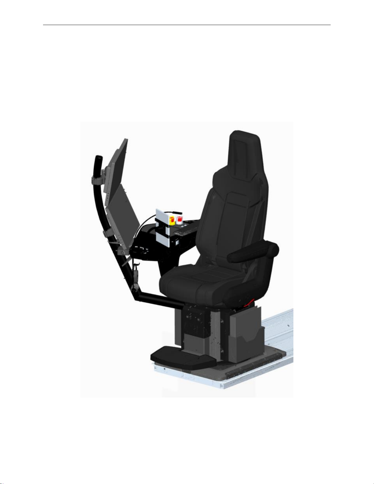
On-board Instructor Station
Configuration
13 Oct 2017
Page 3
2. On-board Instructor Station Configuration
The IOS consists of two touch-sensitive color displays, simulator controls and
accessories, all integrated into a comfortable ergonomic seat, referred to as the
Forward-Facing Instructor Operator Station (FFIOS).
The strategically positioned FFIOS allows for unobstructed visibility on the cockpit,
and easy access to all simulator controls while maintaining optimal ergonomics.
Instructor User Guide
On-board Instructor Station Configuration
Figure 1 On-Board Instructor Station (Typical)
Page 38

Page 39

IOS Software Interface
13 Oct 2017
Page 5
3. IOS Software Interface
This user centric designed IOS has a task centric interface that can adapt quickly to
the user’s intended goal, present relevant functionality and required procedures.
This IOS is used to control and monitor training sessions. It provides the instructor
with the tools to:
• Monitor and assess crew performance.
• Monitor and modify aircraft and environment properties and parameters.
• Control the simulator and exercises.
3.1 IOS Workspaces
The IOS Software Interface consists of the following IOS Workspaces:
• Control Board
o Includes all parameters relating to the ownship.
o Is the main access to ownship parameters.
Instructor User Guide
IOS Software Interface
o Allows values to be changed directly on a panel.
▪ For example, adjusting fuel weights.
o Includes sliding panels
▪ For example, to activate and arm malfunctions.
o Includes a common footer
▪ Providing quick access to common commands.
• Map
o Includes elements relating to the environment.
o Features 2D/3D Map viewable modes.
o Includes environment features such as storms, Navaids stations and
simulated intruders or traffic.
o Displays takeoff/approach/runway and aircraft trail and FMS route.
• Lesson Plan Profile
o Includes all elements relating to a lesson.
o Monitors and controls lesson execution.
o Shows the lessons created in the lesson plan editor.
o Allows the instructor to automatically execute a step instead of entering
individual commands.
Page 40

A320 Neo Instructor Operating Station
IOS Software Interface
13 Oct 2017
Page 6
Instructor User Guide
• Instruments Repeaters
o Allows the instructor to choose which cockpit instrument(s) will be
repeated or displayed on an IOS display screen.
• Maintenance
o Offers pages that allows maintenance personnel to perform various
simulator maintenance tasks.
• Advanced
o Features quick access buttons allowing the instructor to:
▪ Modify Aircraft, Position and Environment parameters.
▪ Perform various types of freeze and resets.
▪ Trigger failures.
▪ Access additional pages
Changing the current IOS workspace is performed through a Workspace button on the
Control Board footer. Tapping this button displays a Workspace rollup menu that
shows all available workspaces.
3.2 User Interface (UI) Controls
The IOS Software Interface includes sliding panels and basic controls that are
common to various workspaces, controls such as:
• Text field
• Read only field
• Indicator
• Button
• Roll-up menu
• Wheel Picker
3.2.1 Sliding Panel
A Sliding Panel is the main type subpage that:
• Is accessible from most workspaces.
• Slides into view from the left-hand side of the screen.
• Slides back out of view by:
o Exercising a left swipe movement, or
o Tapping outside of the sliding panel area.
Page 41

IOS Software Interface
13 Oct 2017
Page 7
In a sliding panel, data entry in the text fields are immediately active except in special
instances. Exceptions are noticeable by an action button that will glow to get user’s
attention.
3.2.2 Text Field
To activate a text field:
• Tap or left mouse click on the text field.
• This action displays the appropriate keyboard required for data entry.
3.2.3 Read Only Field
A read-only field provides status and requires no action on the part of the user.
3.2.4 Indicators
Indicators show the state of a component.
3.2.5 Button
Instructor User Guide
IOS Software Interface
To activate a button:
• Tap or left mouse click to activate button.
• Once selected, button illuminates light blue.
3.2.6 Roll-up menu
To activate a roll-up menu:
• Tap or left mouse click to activate.
• Select desired option.
• Tap anywhere to cancel.
3.2.7 Wheel Picker
The Wheel Picker allows the instructor to adjust a parameter on the Control Board.
Refer to paragraph 3.3.9 for details.
Page 42

A320 Neo Instructor Operating Station
IOS Software Interface
13 Oct 2017
Page 8
Instructor User Guide
3.3 Selecting Parameters and Entering Data
Selecting parameters and entering data on the Control Board or other workspaces is
done by:
• Tapping on a parameter text field
• Quick Access Buttons
• Dropdown Buttons
• Selection Buttons
• Expandable Buttons
• Radio Buttons
• Checkbox
• Sliders
• Wheel Picker
• Keypad
• Interactive Graphs
3.3.1 Tapping on a Parameter Text Field
Tapping on a parameter text field displays either the respective sliding panel or a
keypad.
3.3.2 Quick Access Buttons
Tapping on a Quick Access button displays the respective sliding panel.
Figure 2 Quick Access Buttons (Typical)
Page 43
IOS Software Interface
13 Oct 2017
Page 9
3.3.3 Dropdown Buttons
Normal State
Activated State
Disabled State
Normal State
Activated State
Tapping on a Dropdown button expands the selection for a particular item.
3.3.4 Selection Buttons
There are three types of selections buttons:
• Toggle Normal
• Toggle Fail
• Action
Instructor User Guide
IOS Software Interface
Figure 3 Dropdown Button
3.3.4.1 Toggle Normal Button
A Toggle Normal button has the following states:
3.3.4.2 Toggle Fail Button
A Toggle Fail button has the following states:
Page 44
A320 Neo Instructor Operating Station
IOS Software Interface
13 Oct 2017
Page 10
Normal State
Activated State (for a few seconds)
Disabled State
Instructor User Guide
Once a Toggle Fail button is triggered, the fault is recorded by the Control Board and
displayed in Malfunctions sections, Control Board Footer and in the
MALFUNCTIONS sliding panel.
From the red activated state, tap the toggle fail button again to deactivate the
malfunction.
3.3.4.3 Action Button
An Action button has the following states:
The sequence of states of an Action button is as follows:
• Starts in the Normal State.
• Once the instructor taps on the button, button illuminates for a few seconds.
• Then, the Action button returns to either:
o Normal state, or
o Disabled state.
The return to either the Normal state or Disabled state depends on various conditions.
3.3.5 Expandable Buttons
Tapping on an Expandable button displays the associated sliding panel.
Figure 4 Expandable Button
Page 45
IOS Software Interface
13 Oct 2017
Page 11
3.3.6 Radio Buttons
Tapping on a Radio button allows the instructor to select only one of the predefined
set of options. These buttons are mutually exclusive.
3.3.7 Checkbox
A checkbox is a toggle feature that selects or deselects a particular item.
Instructor User Guide
IOS Software Interface
Figure 5 Radio Button
3.3.8 Sliders
Sliders can also be referred to as slider controls or scroll bars. These can come in
various forms but they all allow the adjustment of a particular item from a minimum
to a maximum value.
Figure 6 Checkbox
Figure 7 Slider
Page 46
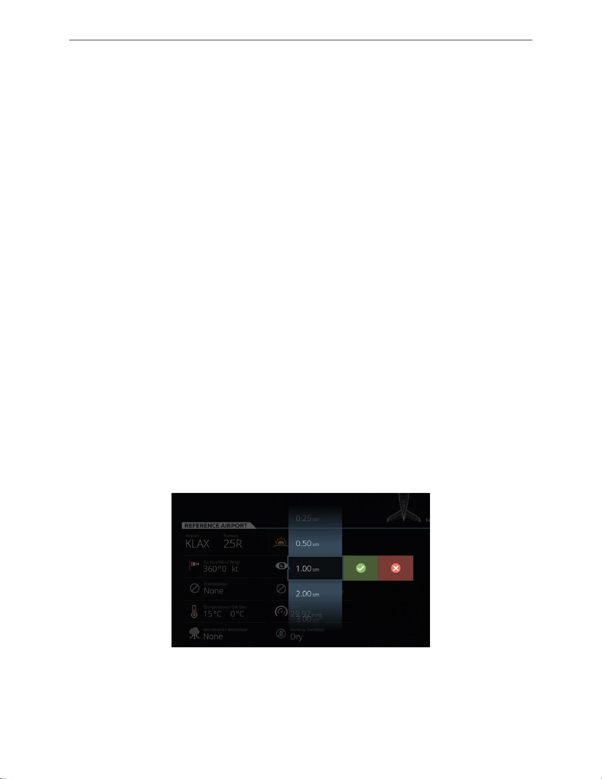
A320 Neo Instructor Operating Station
IOS Software Interface
13 Oct 2017
Page 12
Instructor User Guide
3.3.9 Wheel Picker
Depending on the configuration of the IOS Control Board, some parameters can be
adjusted with a Wheel Picker. To activate the Wheel Picker for a specific item,
proceed as follows:
• Choose a specific parameter.
• Press and hold on this parameter until the Wheel Picker is displayed or slide this
parameter up or down to display the Wheel Picker.
• Scroll through the selection and select:
o The green checkmark to confirm your selection.
o The red X to cancel your selection.
Depending on the IOS configuration, the following lists some of the parameters that
can be adjusted with the wheel picker are:
• Weight
• Time of day
• Reference airport
• Runway
• Runway conditions
• Surface wind
• Precipitation
• Temperature
• QNH
Figure 8 Wheel Picker (Typical)
Page 47
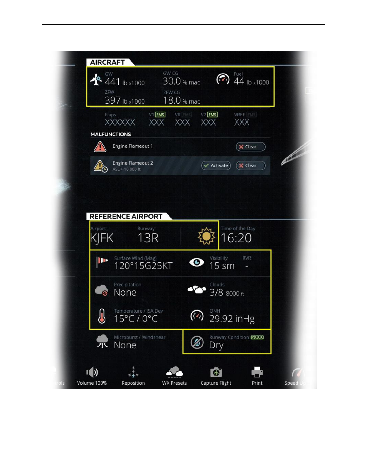
Instructor User Guide
IOS Software Interface
13 Oct 2017
Page 13
IOS Software Interface
Figure 9 Wheel Picker – Adjustable Parameters (Typical)
Page 48
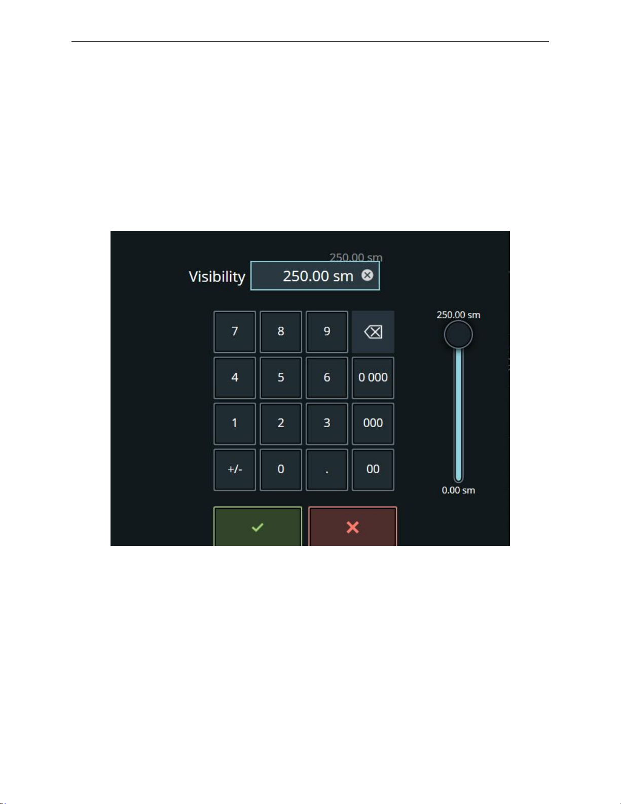
A320 Neo Instructor Operating Station
IOS Software Interface
13 Oct 2017
Page 14
Instructor User Guide
3.3.10 Keypad
Numerous parameters can be adjusted with a keypad. Entering a value in the keypad
can be done either with the slider or with the keypad keys.
The green checkmark confirms the entry and the red X cancels the entry.
Figure 10 Keypad
Page 49
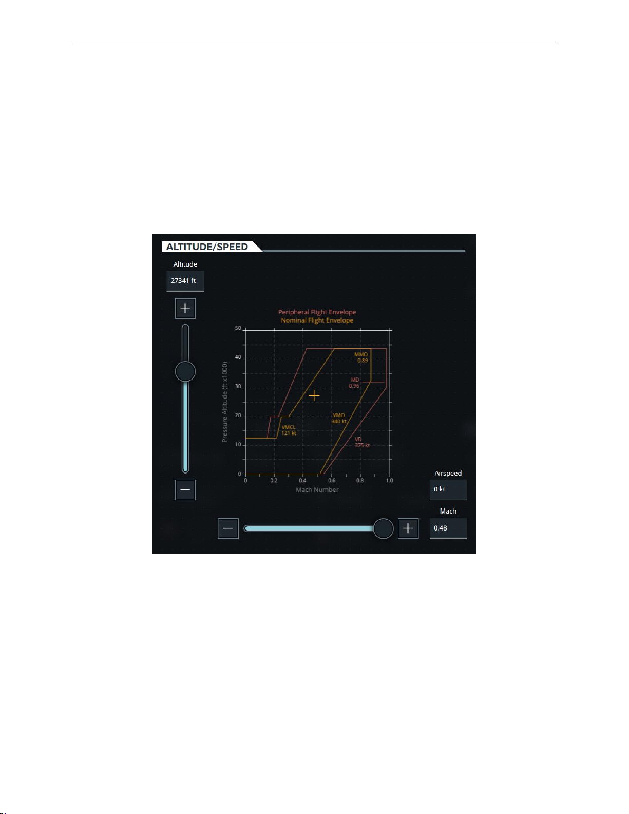
IOS Software Interface
13 Oct 2017
Page 15
3.3.11 Interactive Graphs
Some graphs are interactive and allow the instructor to alter values by simply
touching elements on the graph.
In the Slew graph below for example, the instructor can move the + on the graph
which will cause the sliders and text fields to be updated according to the new +
position on the graph.
Instructor User Guide
IOS Software Interface
Figure 11 Interactive Graphs (Typical)
Page 50

Page 51
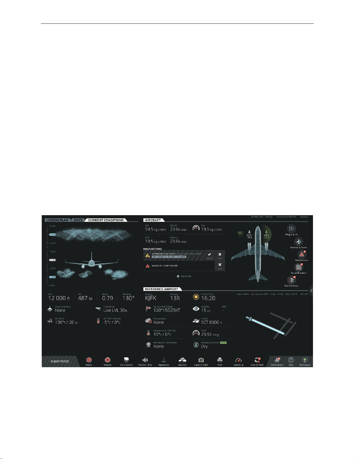
Control Board Workspace
13 Oct 2017
Page 17
4. Control Board Workspace
The Control Board workspace consolidates all the ownship parameters required to
control and monitor various aspects of a training session. It features a set of tabs that
groups all required ownship and environmental parameters by type.
In this IOS configuration the Control Board workspace includes the following tabs:
• LESSON PLAN
• DOCS
• CURRENT CONDITIONS
• AIRCRAFT
• REFERENCE AIRPORT
The Control Board also includes an INSTRUCTOR STATION sliding panel
accessible by the expand button located at the right side of the Control Board. This
sliding panel allows the instructor to set various Unit of Measures.
Instructor User Guide
Control Board Workspace
Figure 12 Control Board – Main View
Page 52
A320 Neo Instructor Operating Station
Control Board Workspace
13 Oct 2017
Page 18
Tabs
Section
Wheel Picker
Interface Element
Current
Conditions
Clouds
Tap to open sliding panel
Attitude Indicators
Tap to open sliding panel
Icing Conditions
Yes
Tap to open sliding panel
Turbulence
Tap to open sliding panel
A/C Wind
Text field
A/C OAT/ ISA Dev
Text field
Aircraft
GW
Yes
Text field
GW CG
Yes
Text field
Fuel
Yes
Text field
ZFW
Yes
Text field
ZFW CG
Yes
Text field
Malfunctions
Section showing number of
active/armed malfunctions
Data Link (DL)
Tap to open sliding panel
Communications (VHF)
Tap to open sliding panel
Weight & CG
Tap to open sliding panel
Services & Doors
Tap to open sliding panel
Malfunctions
Tap to open sliding panel
Circuit Breakers
Tap to open sliding panel
Fail Summary
Tap to open sliding panel
Reference
Airport
Airport & Runway
Yes
Tap to open sliding panel
Time of Day
Yes
Text field
Surface Wind
Yes
Tap to open sliding panel
Visibility
Yes
Text field
RVR
Yes
Tap to open sliding panel
Precipitation
Yes
Tap to open sliding panel
Clouds
Yes
Tap to open sliding panel
Temperature / ISA Dev
Yes
Text field
QNH
Yes
Text field
Microburst/ Windshear
Yes
Tap to open sliding panel
Runway condition
Yes
Tap to open sliding panel
Instructor User Guide
4.1 Tabs and Interface Elements
The interface elements included in each tab of the Control Board are included in this
table.
Table 1 Control Board Interface Elements
Page 53

Instructor User Guide
Control Board Workspace
13 Oct 2017
Page 19
Footer
Flight Freeze
Button
Resets
Button with roll up menu
Freezes
Button with roll up menu
Sim Controls
Button with roll up menu
Volume 100%
Button with roll up menu
Reposition
Button with roll up menu
WX Presets
Button with roll up menu
Capture Flight
Button
Print
Button with roll up menu
Clear All Malfunctions
Button confirmation – disabled
when no active malfunction, badge
shows number of malfunctions
Notifications
Button activates notification view
Help
Button with roll up menu
Workspace
Button with roll up menu
Control Board Workspace
Page 54

Page 55
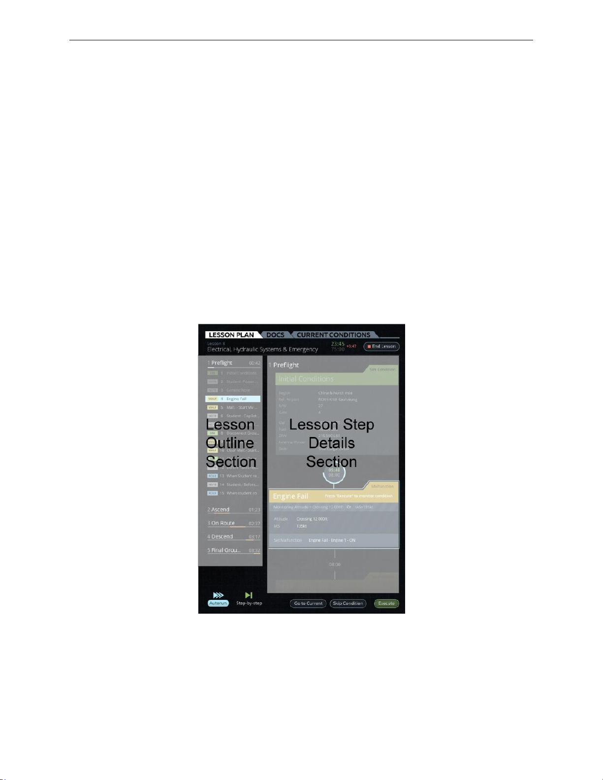
LESSON PLAN Tab
13 Oct 2017
Page 21
5. LESSON PLAN Tab
The LESSON PLAN Tab allows the instructor to:
• View all available lessons on the IOS
• View all the training phases of a lesson
• View all the lesson steps included in a lesson
• Run a lesson automatically or step-by-step
The LESSON PLAN Tab includes:
• Two main sections:
o Lesson Outline (Left side of tab)
o Lesson Step Details (Right side of tab)
• Buttons to control the execution of the lesson
Instructor User Guide
LESSON PLAN Tab
Figure 13 LESSON PLAN Outline and Details
Page 56
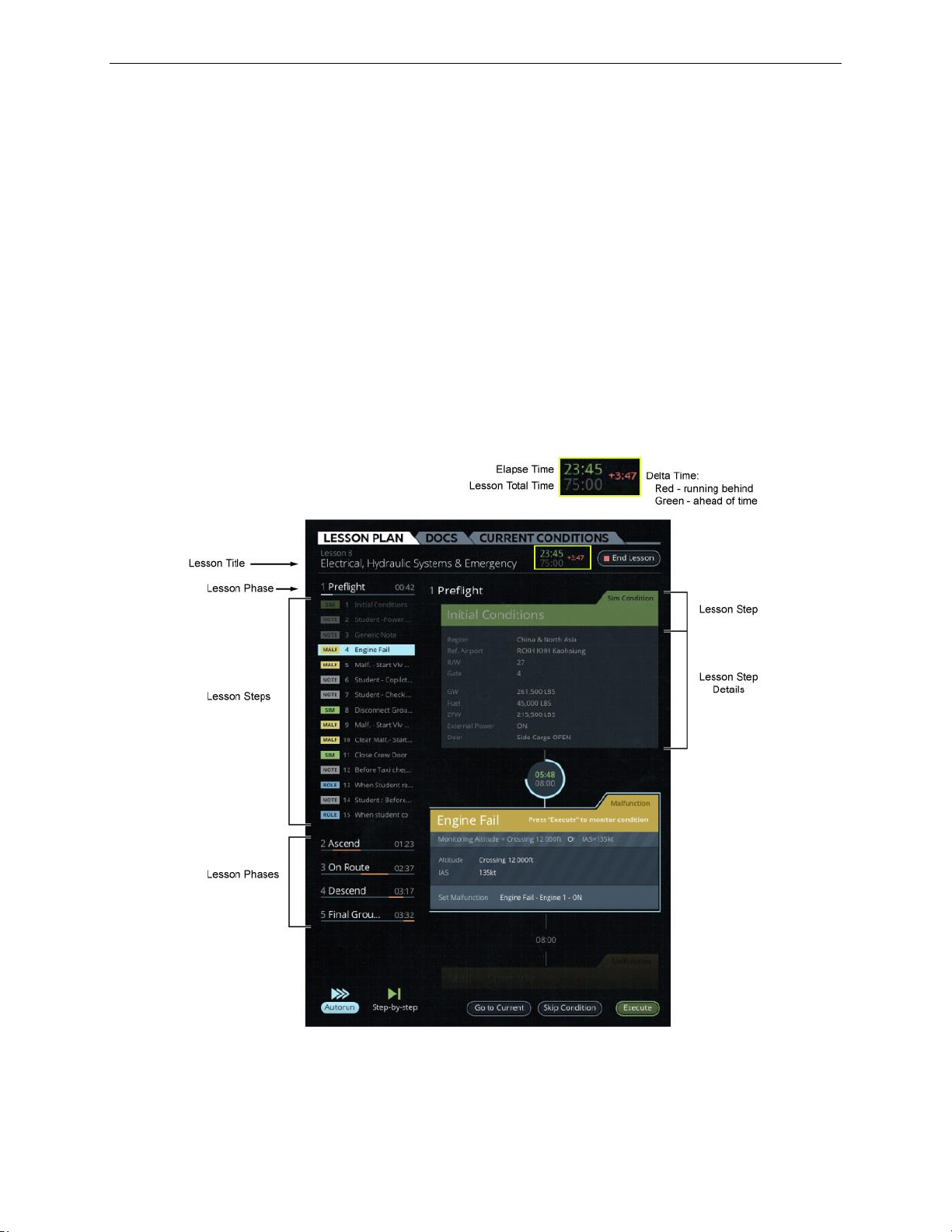
A320 Neo Instructor Operating Station
LESSON PLAN Tab
13 Oct 2017
Page 22
Instructor User Guide
All lessons available on the IOS Control Board are created with the CAE Slick webbased lesson plan editor (Refer to TPD 19709 Slick User Guide for more details).
This application editor provides all necessary controls to allow an instructor to:
• Create a lesson by adding all the necessary lesson elements:
o Notes
o Simulator condition
o Malfunctions
o Freeplay button
• Modify a lesson
This application editor allows the instructor to add all necessary elements available on
the IOS to create a fully automated training environment lesson.
Figure 14 LESSON PLAN Tab
Page 57

LESSON PLAN Tab
13 Oct 2017
Page 23
5.1 Lesson Outline Section
For a selected lesson, the Lesson Outline section lists all:
• Training phases of the lesson.
• All the steps included in each training phase.
5.2 Lesson Step Details Section
The Lesson Step Details section is scrollable; it allows the instructor to scroll up and
down and visualize the details of each lesson step.
5.3 Lesson Training Phases
A lesson plan may be structured and organized in phases that will allow the training
session to meet the training lesson objective(s). Lesson training phases defined by the
instructor can be structured to match the various phases of flight or training tasks.
5.4 Lesson Steps
Lesson steps inserted in a lesson training phase can be categorized as:
• Note
Instructor User Guide
LESSON PLAN Tab
o This a read-only step providing information to the instructor.
• Sim Condition
o This step allows the instructor to execute a single instruction or several
instructions to alter the state of the simulation.
• Malfunction
o This step allows the instructor to insert a malfunction in the lesson plan
along with all the malfunction trigger criteria.
• Freeplay button
o This button allows the instructor to trigger a pre-program action or set of
actions that can be triggered at any time during the lesson plan.
• Nested Lesson
o This step allows the instructor to connect or link to another lesson.
Page 58

A320 Neo Instructor Operating Station
LESSON PLAN Tab
13 Oct 2017
Page 24
Instructor User Guide
In a lesson plan, these are identified with the following flags:
Figure 15 Lesson Step Flags
5.5 LESSON PLAN Tab Buttons
The LESSON PLAN tab includes the following buttons.
5.5.1 Autorun
Tap this button to run lesson steps that have been set to run automatically.
5.5.2 Step-by-step
Tap this button to run the lesson steps in a step-by-step fashion. For each step to be
issued, requires a confirmation from the instructor which is done by tapping the
Execute button.
5.5.3 Go to Current
Tap this button to display the current lesson step in the Lesson Step Details Section.
5.5.4 Skip Condition
Tap this button to skip a condition associated to specific lesson step.
5.5.5 Execute
Tap this button to execute the current lesson step.
5.5.6 End Lesson
Tap this button to end the current lesson.
Page 59
DOCS Tab
13 Oct 2017
Page 25
6. DOCS Tab
The DOCS Tab allows the instructor to view reference documentation. The DOCS
Tab includes the following controls.
6.1 Thumbnail View
Provides a list of small graphic representation of each larger page.
6.2 List View
Provides a list of all the page titles.
6.3 Scroll Up and Down
Scrolls up and down through the document in a Next page, Previous page
fashion.
6.4 Search Function
Instructor User Guide
DOCS Tab
Allows the instructor to search for a word or a string of characters.
6.5 View Expansion
Expands the view of the viewable document.
6.6 Zoom
Zoom-in and out controls.
Page 60
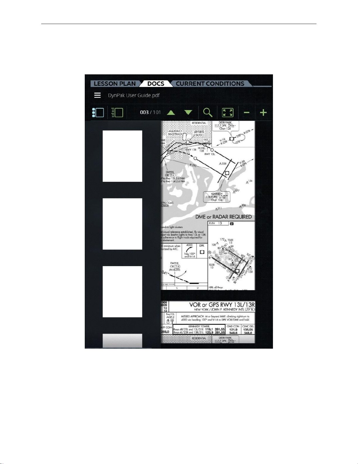
A320 Neo Instructor Operating Station
DOCS Tab
13 Oct 2017
Page 26
Instructor User Guide
Figure 16 DOCS Tab
Page 61
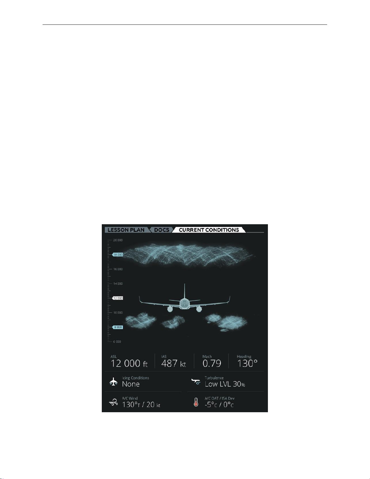
CURRENT CONDITIONS Tab
13 Oct 2017
Page 27
7. CURRENT CONDITIONS Tab
The CURRENT CONDITIONS tab provides an overall status of the aircraft ownship
situation and the environmental conditions at the ownship.
This tab includes all the necessary controls to allow the instructor to view and change:
• Ownship situation parameters such as:
o Altitude
o Airspeed
o Heading
• Environmental conditions at the ownship such as:
o Clouds, fog and visibility
o Icing conditions
o Turbulence
Instructor User Guide
CURRENT CONDITIONS Tab
o Winds
o Outside Air Temperature
Figure 17 CURRENT CONDITIONS Tab
Page 62

A320 Neo Instructor Operating Station
CURRENT CONDITIONS Tab
13 Oct 2017
Page 28
Instructor User Guide
7.1 Parameter Input Text Fields
The CURRENT CONDITIONS tab includes parameter input text fields that upon
tapping will display the associated sliding panel or keypad.
Some parameters in this tab can also be adjusted using the Wheel Picker. To use the
wheel picker:
• Press and hold on a parameter until the Wheel Picker is displayed or swipe this
parameter up or down to display the Wheel Picker.
• Scroll through the selection and select:
o The green checkmark to confirm your selection.
o The red X to cancel your selection.
7.1.1 Clouds and Visibility Section
This section of the CURRENT CONDITIONS tab displays the current cloud settings
at a geographic region where the aircraft is flying. Tap on this section to display the
CLOUDS at the aircraft sliding panel.
7.1.2 ASL
This input text field displays the current Above Sea Level (ASL) aircraft altitude. Tap
on this input text field to display the SLEW sliding panel and change the aircraft
altitude.
7.1.3 IAS
This input text field displays the current Indicated Airspeed (IAS). Tap on this input
text field to display the SLEW sliding panel and change the IAS.
7.1.4 Mach
This input text field displays the current Mach speed. Tap on this input text field to
display the SLEW sliding panel and change the Mach speed.
7.1.5 Heading
This input text field displays the current aircraft heading. Tap on this input text field
to display the SLEW sliding panel and change the aircraft heading.
Page 63

CURRENT CONDITIONS Tab
13 Oct 2017
Page 29
7.1.6 Icing Conditions
This input text field displays the current aircraft icing conditions.
To modify the icing conditions either:
• Tap on this input text field to display the ICING sliding panel, or
• Use the Wheel Picker.
7.1.7 Turbulence
This input text field displays the current turbulence condition at the aircraft. Tap on
this input text field to display the TURBULENCE sliding panel and change the
turbulence condition at the aircraft.
7.1.8 A/C Wind
This input text field displays the current wind direction and speed at the aircraft
(A/C). Tap on the A/C Wind input text field to display the A/C Wind Direction Speed
keypad. Use the keypad to change the wind direction and speed.
Instructor User Guide
CURRENT CONDITIONS Tab
7.1.9 A/C OAT
This input text field displays the current Outside Air Temperature (OAT) at the
aircraft (A/C).
To modify the OAT at the aircraft either:
• Tap on A/C OAT to display the A/C OAT keypad.
• Use this keypad to change the temperature or use the Wheel Picker.
7.1.10 A/C ISA Dev
This input text field displays the current International Standard Atmosphere (ISA)
Deviation (ISA Dev).
To modify the ISA Deviation at the aircraft either:
• Tap on ISA Dev to display the ISA Dev keypad.
• Use this keypad to change the ISA deviation or use the Wheel Picker.
7.2 CLOUDS AT AIRCRAFT Sliding Panel
The CLOUDS AT AIRCRAFT sliding panel allows the instructor to modify cloud
and visibility parameters at the region around the ownship by choosing:
• The types of clouds at various levels
• Cloud thickness
• Visibility
Page 64
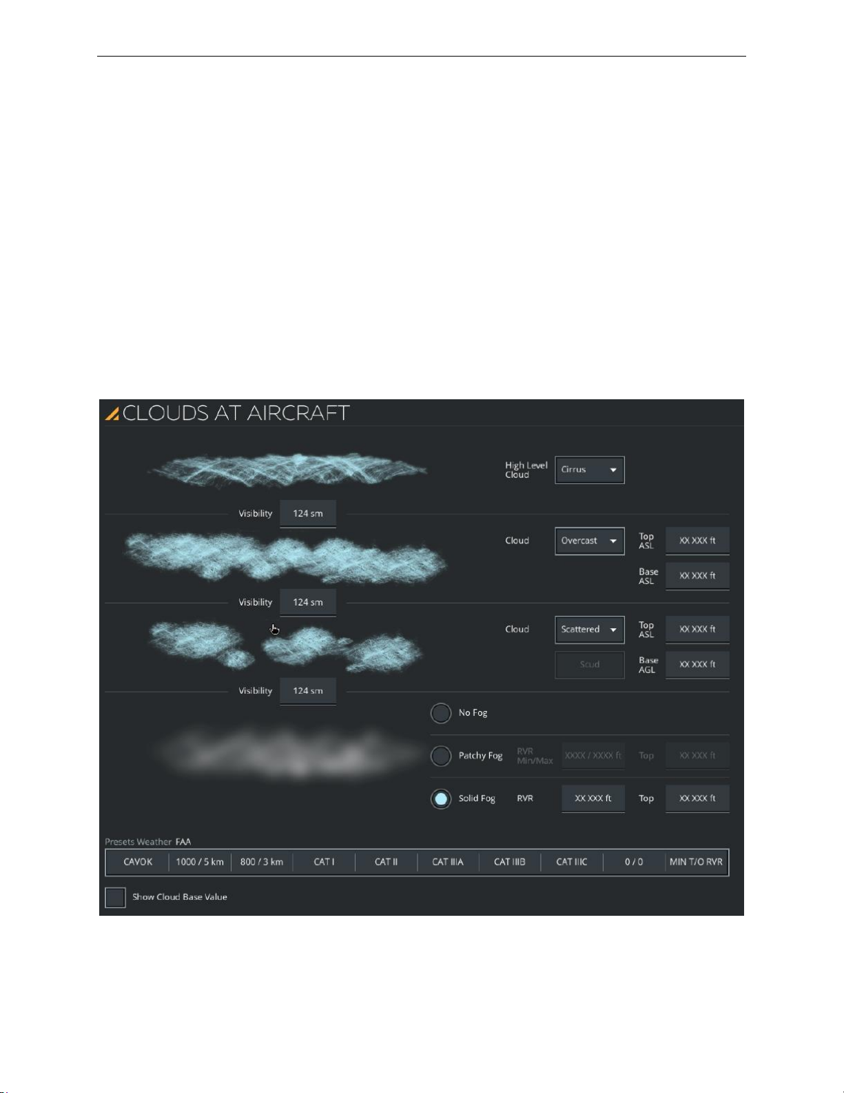
A320 Neo Instructor Operating Station
CURRENT CONDITIONS Tab
13 Oct 2017
Page 30
Instructor User Guide
• Type of fog, and
• Weather presets visual conditions
This panel includes:
• Dropdown buttons to select the types of clouds and cloud density
• Input text fields to enter the upper and lower limits of the cloud layer
• The following sections:
o Visibility
o Cloud levels
o Fog
o Weather presets
Figure 18 CLOUDS AT AIRCRAFT Sliding Panel (Typical)
Page 65

CURRENT CONDITIONS Tab
13 Oct 2017
Page 31
7.2.1 Visibility Section
This section includes visibility input text fields that display the visibility between
cloud layers.
Maximum visibility is limited if rain is activated:
• 15 nm for light rain
• 5 nm for moderate rain
• 1 nm for heavy rain
To adjust the visibility, tap on the input text field and use the keypad to enter new
value (Min = 0, Max = Dynamic). Can also be displayed in Statute Mile (sm).
7.2.2 Cloud Level Section
7.2.2.1 High Level Cloud
Instructor User Guide
CURRENT CONDITIONS Tab
Tap on this dropdown button to expand selection and view the full cloud selection,
then make your selection.
Selection of high clouds includes:
• None
• Cirrocumulus
• Cirrus
• Cirrostratus
7.2.2.2 Medium Level Cloud
Tap on this dropdown button to expand selection and view the full cloud selection,
then make your selection.
Selection of medium clouds includes:
• Clear
• Scattered
• Broken
• Overcast
Page 66

A320 Neo Instructor Operating Station
CURRENT CONDITIONS Tab
13 Oct 2017
Page 32
Instructor User Guide
7.2.2.3 Low Level Cloud
Tap on this dropdown button to expand selection and view the full cloud selection,
then make your selection.
Selection of low level clouds includes:
• Clear
• Scattered
• Broken
• Overcast
7.2.2.4 Medium Level Cloud Thickness
The cloud thickness of the medium level clouds is set by two input text field that
establish the upper and lower limits of the cloud layer.
Tap on the Top ASL input text field to set the cloud top limit and then tap on the Base
ASL input text field to set the lower limit.
Values are displayed in feet. The minimum and maximum cloud layer thickness
depends on the type of coverage.
Note: The input text fields can sometimes be defined as MSL.
7.2.2.5 Low Level Cloud Thickness
The cloud thickness of the low-level clouds is set by two input text field that establish
the upper and lower limits of the cloud layer.
Tap on the Top ASL input text field to set the cloud top limit and then tap on the Base
AGL input text field to set the lower limit.
Values are displayed in feet. The minimum and maximum cloud layer thickness
depends on the type of coverage.
Note: The input text fields can sometimes be defined as MSL and AGL.
7.2.3 Fog Section
The Fog section includes three radio buttons that are mutually exclusive.
7.2.3.1 No Fog
Tap this radio button to remove the fog.
Page 67

CURRENT CONDITIONS Tab
13 Oct 2017
Page 33
7.2.3.2 Patchy Fog and Thickness
Tap this radio button to activate patchy fog conditions.
When patchy fog is activated, the fog thickness varies randomly between the preset
minimum and maximum Runway Visual Range (RVR) and the altitude set by the
Patchy Fog Top value in ft.
7.2.3.3 Solid Fog and Thickness
Tap this radio button to activate solid fog conditions.
When solid fog is activated, the fog thickness varies between the given minimum and
maximum RVRs. Selection allows inputs ranges of RVR and Top (feet) in the text
field.
7.2.3.4 RVR Min/Max
Tap each input text field to enter the minimum/maximum Runway Visual Range
(RVR) (meters/feet). This button is only available when patchy fog is active.
Instructor User Guide
CURRENT CONDITIONS Tab
RVR MIN
(Min = 0, Max = RVR max)
RVR MAX
(Min = RVR min, Max = 3045 meters)
(Min = RVR min, Max = 9990 feet)
7.2.4 Weather Presets Section
This section includes buttons that change the cloud and visibility conditions
according to FAA, EASA, TCA or EUR standards (As applicable).
7.2.4.1 CAVOK
Tap this button to activate CAVOK conditions on the visual display.
Conditions are:
• No cloud base below 5000 feet; no cumulonimbus.
• Visibility 6 statute miles/10 kilometers or more.
• No precipitation, thunderstorms, shallow fog, or low drifting snow.
7.2.4.2 1000/5km
Tap this button to activate CIRCLING with 1000/5km conditions on the visual
display.
Page 68

A320 Neo Instructor Operating Station
CURRENT CONDITIONS Tab
13 Oct 2017
Page 34
Instructor User Guide
7.2.4.3 800/2km
Tap this button to activate CIRCLING with 800/2km conditions on the visual display.
7.2.4.4 CAT I
Tap this button to activate CAT I conditions on the visual display.
7.2.4.5 CAT II
Tap this button to activate CAT II conditions on the visual display.
7.2.4.6 CAT IIIA
Tap this button to activate CAT IIIA conditions on the visual display.
7.2.4.7 CAT IIIB
Tap this button to activate CAT IIIB conditions on the visual display.
7.2.4.8 CAT IIIC
Tap this button to activate CAT IIIC conditions on the visual display.
7.2.4.9 0/0
Tap this button to activate 0/0 conditions on the visual display.
7.2.4.10 MIN T/O RVR
Tap to activate MIN T/O RVR conditions on the visual display.
7.3 SLEW Sliding Panel
The SLEW sliding panel allows the instructor to view and change the aircraft:
• Altitude
• Indicated airspeed
• Heading and position
Position slew is possible when position freeze is activated. Below 100 feet above
ground level, the aircraft height above ground will be maintained as the position is
slewed. Altitude and speed slew are inhibited while the aircraft is on ground.
This sliding panel includes two main tabs:
• ALTITUDE/SPEED
• HEADING/POSITION
Page 69
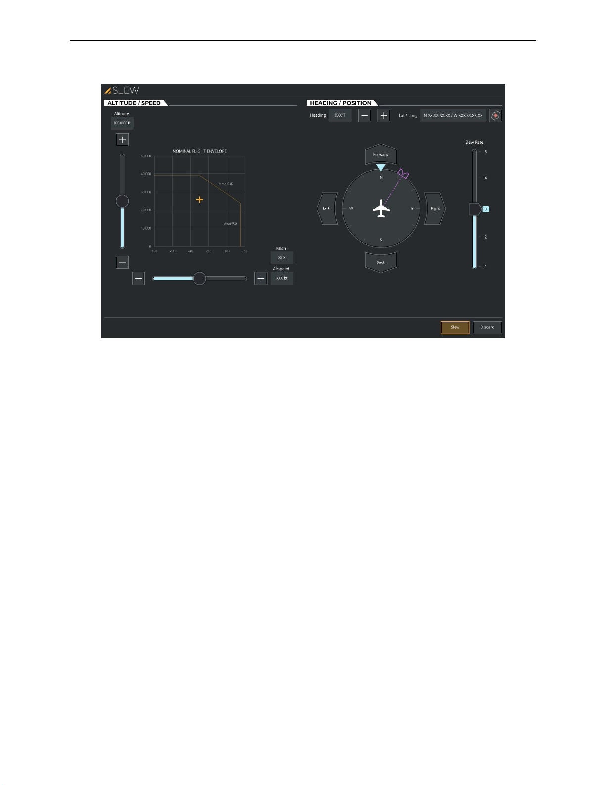
Instructor User Guide
CURRENT CONDITIONS Tab
13 Oct 2017
Page 35
CURRENT CONDITIONS Tab
Figure 19 Aircraft SLEW Sliding Panel
7.3.1 ALTITUDE / SPEED Tab
This tab includes the necessary controls to modify the altitude and airspeed of the
aircraft.
7.3.1.1 Altitude
Tap this input text field to display a keypad that will allow you to enter a new altitude
(meters/feet).
Modifying the altitude can be done either through the altitude input text field or with
the Altitude slider. (Dynamic Min/Max).
7.3.1.2 Altitude Slider
Swipe the Altitude slider up (+) or down (-) to increase or decrease the aircraft
altitude (Dynamic Min/Max).
The + button slews the aircraft upwards at a fixed rate and the – button slews the
aircraft downwards at a fixed rate.
7.3.1.3 Airspeed
Tap this input text field to display a keypad that will allow you to enter a new
Indicated Airspeed (IAS) in knots.
Page 70

A320 Neo Instructor Operating Station
CURRENT CONDITIONS Tab
13 Oct 2017
Page 36
Instructor User Guide
Modifying the IAS can be done either through the airspeed input text field or with the
Airspeed slider. (Dynamic Min/Max).
The aircraft is trimmed at the requested speed. Flap and gear position will be driven
as required in order not to create an overspeed condition. Flight freeze is set once
complete. (Dynamic Min/Max).
7.3.1.4 Airspeed Slider
Swipe the Airspeed slider right (+) or left (-) to increase or decrease the aircraft
speed.
The aircraft is trimmed at the requested speed. Flap and gear position will be driven
as required in order not to create an overspeed condition. Flight freeze is set once
complete (Dynamic Min/Max).
The + button slews the aircraft indicated airspeed up at a fixed rate and the – button
slews the aircraft indicated airspeed down at a fixed rate.
7.3.1.5 Mach
Tap this input text field to display a keypad that will allow you to enter a new aircraft
Mach speed.
The aircraft is trimmed at the requested Mach speed. Flap and gear position will be
driven as required in order not to create an overspeed condition. Flight freeze is set
once complete (Dynamic Min/Max).
7.3.1.6 Graph
This graph is interactive as it allows the instructor to alter values by simply touching
elements on the graph.
In this Slew graph, the instructor can move the + on the graph which will cause the
sliders and text fields to be updated according to the new + position on the graph.
7.3.2 HEADING / POSITION Tab
This tab includes the necessary controls to modify the heading and position of the
aircraft.
7.3.2.1 Heading
Tap this input text field to display a keypad that will allow you to enter a new aircraft
heading. No other parameters are affected.
7.3.2.2 Heading Slew Increase (+) / Decrease (-)
The heading (+) button or (–) button slew the aircraft magnetic heading either by
increasing or decreasing it a fixed rate. These buttons are disabled when the magnetic
aircraft heading slew function is not available.
Page 71

CURRENT CONDITIONS Tab
13 Oct 2017
Page 37
7.3.2.3 Forward
Tap this button to slew the aircraft forward. This button is disabled during speed up.
7.3.2.4 Back
Tap this button to slew the aircraft backwards. This button is disabled during speed
up.
7.3.2.5 Left
Tap this button to slew the aircraft to the left. This button is disabled during speed up.
7.3.2.6 Right
Tap this button to slew the aircraft to the right. This button is disabled during speed
up.
7.3.2.7 Lat / Long
Tap this input text field to display a keypad that will allow you to enter new latitude
and longitude coordinates for the aircraft (ownship). This input text field allows the
instructor to reposition the aircraft at a new location.
Instructor User Guide
CURRENT CONDITIONS Tab
7.3.2.8 Hook (Optional)
Tap the Hook button to position the aircraft to the preset Hook geo coordinates
as set by the instructor on the Map workspace. This geographic point has Latitude and
longitude coordinates on the map but it does not have an altitude.
7.3.2.9 Position Slew Rate Slider
Swipe the Position Slew Rate Slider between 1 to 5 to change the rate at which the
slews will function (Min = 1, Max = 5).
7.3.3 Slew
Tap this button to immediately slew the aircraft in accordance with the newly
changed parameters (altitude, speed, heading and position).
This button is disabled when no slew parameters have been selected for change or
while one of the associated slews is active.
7.3.4 Discard
Tap this button to immediately cancel the slew selected parameter changes.
This button is disabled when no slew parameters have been selected for change or
while one of the associated slews is active.
Page 72
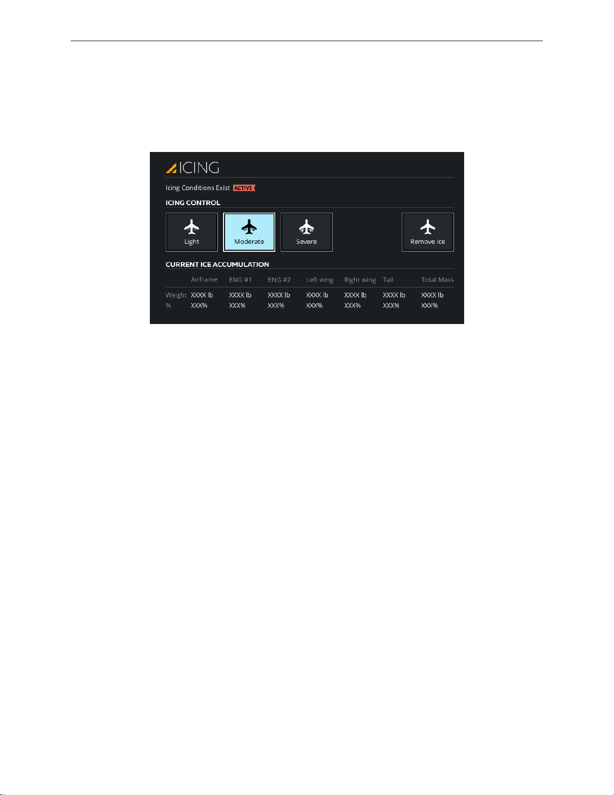
A320 Neo Instructor Operating Station
CURRENT CONDITIONS Tab
13 Oct 2017
Page 38
Instructor User Guide
7.4 ICING Sliding Panel
The ICING sliding panel allows the instructor to control the icing conditions on the
aircraft. The selection of icing conditions on the aircraft is done by selecting either
one of the Light, Moderate or Severe buttons which are mutually exclusive.
Figure 20 ICING Sliding Panel
7.4.1 Icing Conditions Exist
There are two flags to indicate the selection of an icing condition.
An Armed Yellow flag indicates:
• That an icing condition is selected
• The aircraft is not in the icing condition location (not in cloud)
• TAT <6 and >-20 degree Celsius
An Active Red flag indicates:
• That an icing condition is selected
• The aircraft is in the icing condition location (in cloud)
• TAT <6 and >-20 degree Celsius
7.4.2 Light
From the Normal state, tap this button to set the rate and quantity of ice buildup on
the airframe/wing/probe to the light setting (33%).
7.4.3 Moderate
From the Normal state, tap this button to set the rate and quantity of ice buildup on
the airframe/wing/probe to the moderate setting (67%).
Page 73

CURRENT CONDITIONS Tab
13 Oct 2017
Page 39
7.4.4 Severe
From the Normal state, tap this button to set the rate and quantity of ice buildup on
the airframe/wing/probe to the severe setting (100%).
7.4.5 Remove Ice
Tap this button to gradually remove the existing ice buildup condition. Once
completed the icing rate and quantity is set to 0.
7.4.6 ICE ACCUMULATION Section
This section includes read-only text fields that display ice accumulation in weight or
% for certain aircraft components.
7.4.6.1 Weight
The weight read-only text fields display the actual ice accumulation weight in the
selected unit of measure (kilograms/pounds) for the following aircraft components:
• Airframe
Instructor User Guide
CURRENT CONDITIONS Tab
7.4.6.2 %
The % read-only text fields display the actual ice accumulation percentage for the
following aircraft components:
• ENG #1
• ENG #2
• Left Wing
• Right Wing
• Tail
• Total Mass
• Airframe
• ENG #1
• ENG #2
• Left Wing
• Right Wing
• Tail
• Total Mass
Page 74
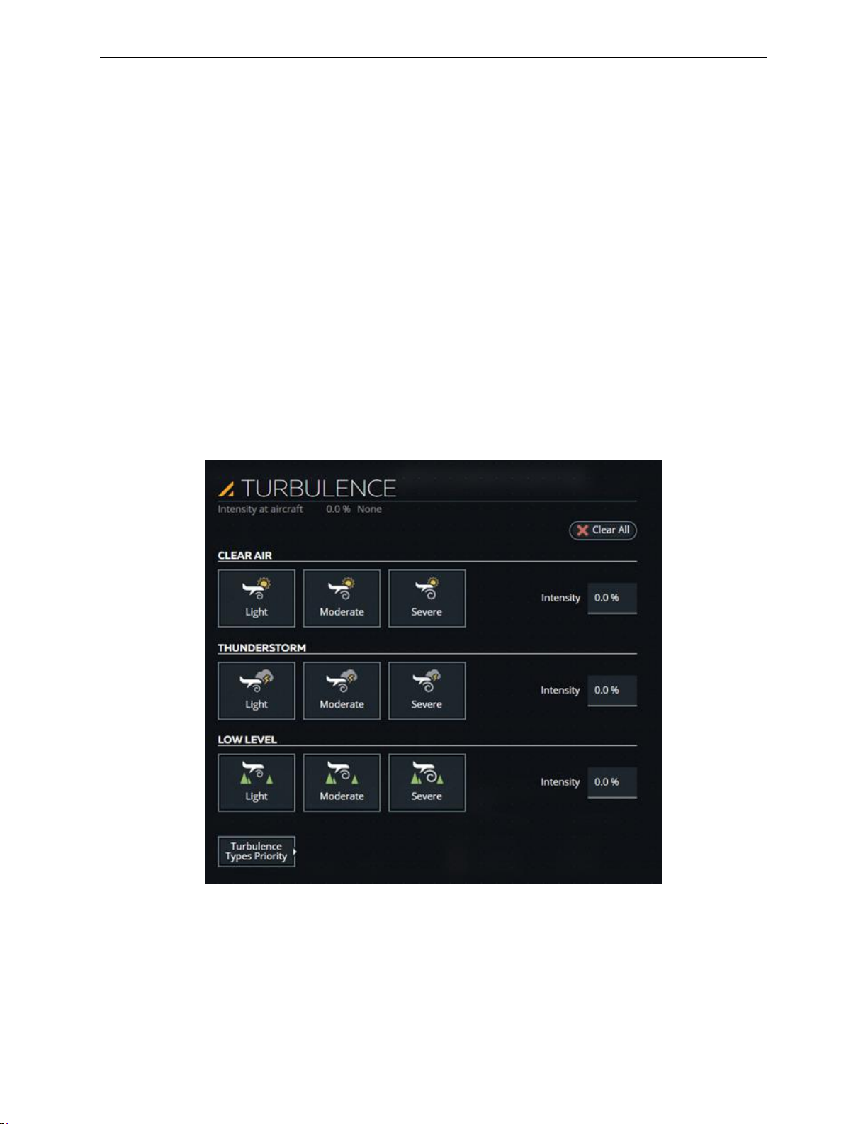
A320 Neo Instructor Operating Station
CURRENT CONDITIONS Tab
13 Oct 2017
Page 40
Instructor User Guide
7.5 TURBULENCE Sliding Panel
The TURBULENCE sliding panel allows the instructor to select various types of
turbulence that can be induced on the aircraft.
This sliding panel offers buttons that are mutually exclusive and allow the instructor
to manually change various turbulence parameters such as:
• Type and,
• Intensity level
It includes the following sections:
• CLEAR AIR
• THUNDERSTORM
• LOW LEVEL
Figure 21 TURBULENCE Sliding Panel
Page 75
CURRENT CONDITIONS Tab
13 Oct 2017
Page 41
7.5.1 CLEAR AIR Turbulence
Altitude ft
Clear Air
>10,000
100%
5,000-10,000
100%
500-5,000
100%
<50
Fades linear
Altitude ft
Thunderstorm
>10,000
100%
5,000-10,000
100%
500-5,000
100%
<50
Fades linear
Clear air turbulence can be felt at all altitudes, except while on ground.
At altitudes below 50 ft AGL, the nominal turbulence intensity is faded linearly as a
function of altitude AGL.
At altitudes above 50 ft AGL, 100% of the nominal turbulence intensity is felt.
7.5.1.1 CLEAR AIR - Light
Tap this button to set the clear air turbulence intensity to light (33%).
Instructor User Guide
CURRENT CONDITIONS Tab
7.5.1.2 CLEAR AIR - Moderate
Tap this button to set the clear air turbulence intensity to moderate (66%).
7.5.1.3 CLEAR AIR - Severe
Tap this button to set the clear air turbulence intensity to severe (100%).
7.5.1.4 Intensity
Tap this input text field to display a keypad that will allow you to modify the intensity
level of the clear air turbulence (Min = 0, Max = 100%).
7.5.2 THUNDERSTORM Turbulence
Thunderstorm turbulence can be felt at all altitudes, except while on ground.
At altitudes below 50 ft AGL, the nominal turbulence intensity is faded linearly as a
function of altitude AGL.
At altitudes above 50 ft AGL, 100% of the nominal turbulence intensity is felt.
Page 76

A320 Neo Instructor Operating Station
CURRENT CONDITIONS Tab
13 Oct 2017
Page 42
Altitude ft
Low Level
>10,000
None
5000-10,000
Fades linear
500-5,000
Fades
exponentially
<50
Ground
Instructor User Guide
7.5.2.1 THUNDERSTORM - Light
Tap this button to set the thunderstorm turbulence intensity to light (33%).
7.5.2.2 THUNDERSTORM - Moderate
Tap this button to set the thunderstorm turbulence intensity to moderate (66%).
7.5.2.3 THUNDERSTORM - Severe
Tap this button to set the thunderstorm turbulence intensity to severe (100%).
7.5.2.4 Intensity
Tap this input text field to display a keypad that will allow you to modify the intensity
level of the thunderstorm turbulence (Min = 0, Max = 100%).
7.5.3 LOW LEVEL Turbulence
Low level turbulence is only felt at certain altitudes.
At altitudes above 500 ft AGL and below 5000 ft AGL, 100% of the nominal low
level turbulence intensity is felt.
At altitudes above 10,000 ft AGL, low level turbulence is not felt.
At altitudes between 5,000 ft AGL and 10000 ft AGL, the nominal turbulence
intensity is linearly faded as a function of altitude AGL.
At altitudes above 50 ft AGL and below 500 ft AGL, the nominal turbulence intensity
is exponentially faded as a function of altitude AGL.
At altitudes below 50 ft AGL, the nominal turbulence intensity is linearly faded as a
function of altitude AGL. Low level turbulence is not felt while on the ground.
7.5.3.1 LOW LEVEL Turbulence - Light
Tap this button to set the low-level turbulence intensity to light (33%).
7.5.3.2 LOW LEVEL Turbulence – Moderate
Tap this button to set the low-level turbulence intensity to moderate (66%).
Page 77

CURRENT CONDITIONS Tab
13 Oct 2017
Page 43
7.5.3.3 LOW LEVEL Turbulence – Severe
Tap this button to set the low-level turbulence intensity to severe (100%).
7.5.3.4 Intensity
Tap this input text field to display a keypad that will allow you to modify the intensity
level of the low-level turbulence (Min = 0, Max = 100%).
7.5.4 Clear All
Tap this button to clear all active turbulence types from the environment.
7.5.5 Turbulence Types Priority
Tap this expandable button to display the TURBULENCE TYPES PRIORITY
Sliding Panel.
Instructor User Guide
CURRENT CONDITIONS Tab
Page 78
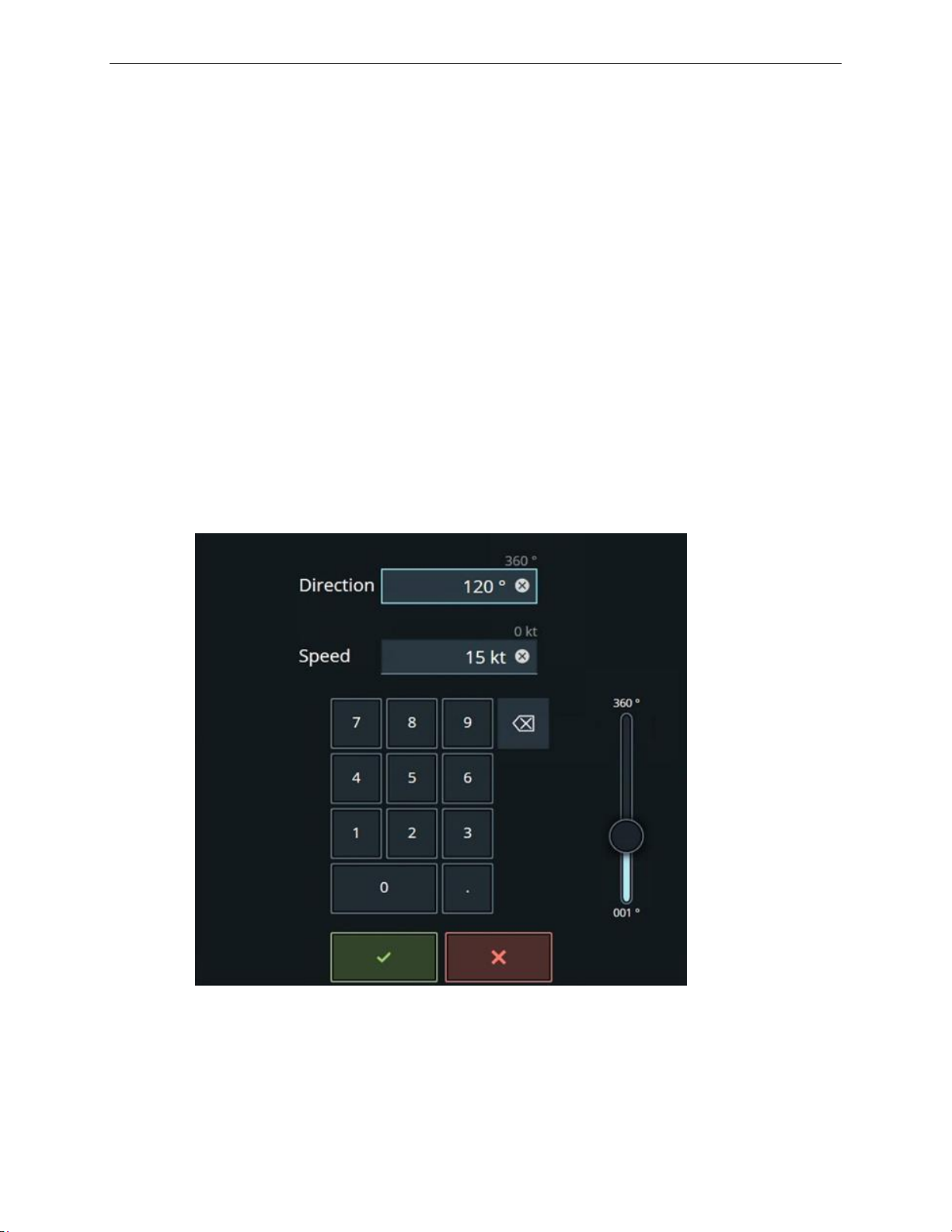
A320 Neo Instructor Operating Station
CURRENT CONDITIONS Tab
13 Oct 2017
Page 44
Instructor User Guide
7.6 A/C Wind Keypad
The A/C Wind keypad displays the current wind direction and speed at the aircraft
location.
To change the A/C wind direction and speed at the aircraft location:
1) Use the keypad or the slider control to enter a new magnetic wind direction and
speed at the aircraft.
2) Tap on the green checkmark to confirm your selection or the red X to cancel
the entry.
The wind direction varies between 1° to 360°.
If flight freeze is not active, a change to A/C wind direction and speed is immediately
ramped, at a pre-determined rate, to the requested value.
If flight freeze is active, a change to the A/C wind direction and speed is delayed until
flight freeze is released.
Figure 22 A/C Wind Direction Keypad
Page 79
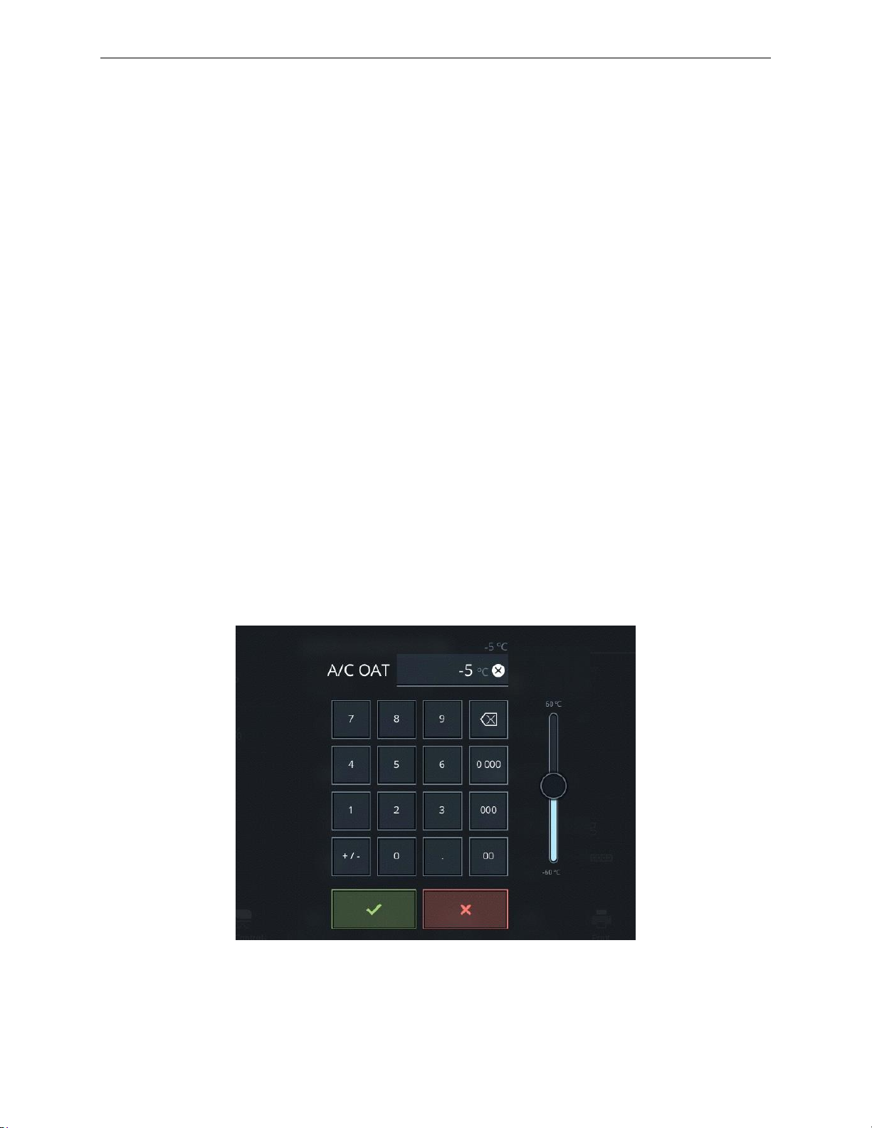
CURRENT CONDITIONS Tab
13 Oct 2017
Page 45
7.7 A/C OAT Keypad
The A/C OAT keypad displays the current Outside Air Temperature (OAT) at the
aircraft location.
To change the A/C OAT at the aircraft location:
1) Use the keypad or the slider control to enter a new OAT at the aircraft.
2) Tap on the green checkmark to confirm your selection or the red X to cancel
the entry.
The entire temperature profile will be offset by the change in the OAT (Dynamic
Min/Max).
If the aircraft is on the ground, the OAT change is instantaneous regardless of flight
freeze.
If the aircraft is in the air and flight freeze is not active, a change to OAT is
immediately ramped, at a pre-determined rate, to the requested value.
Instructor User Guide
CURRENT CONDITIONS Tab
If the aircraft is in the air and flight freeze is active, a change to OAT is delayed until
flight freeze is released.
The advisory message, Temperature is Changing, will appear in the warning footer
area of the IOS until the change is completed. The ramped OAT reading will be
indicated on the IOS while the new value is reached.
Figure 23 A/C OAT Keypad
Page 80
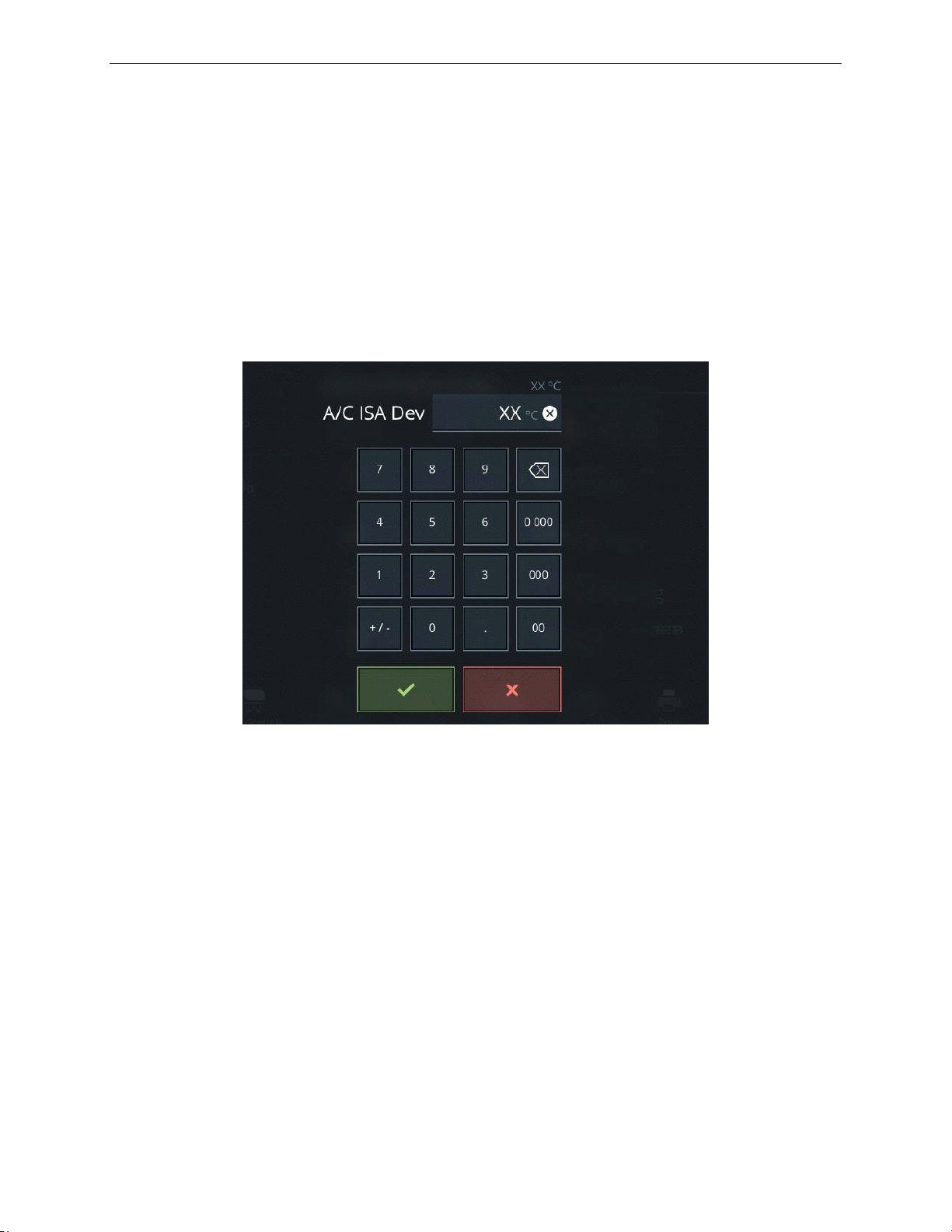
A320 Neo Instructor Operating Station
CURRENT CONDITIONS Tab
13 Oct 2017
Page 46
Instructor User Guide
7.8 A/C ISA Dev Keypad
The A/C ISA Dev keypad displays the current ISA temperature deviation at the
aircraft location.
To change the ISA temperature deviation at the aircraft location:
1) Use the keypad to enter a new ISA deviation at the aircraft.
2) Tap on the green checkmark to confirm your selection or the red X to cancel
the entry.
Figure 24 ISA Dev Keypad
Page 81
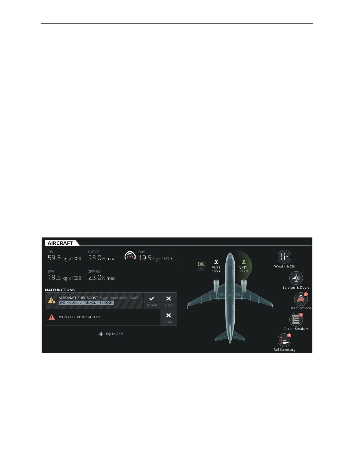
AIRCRAFT Tab
13 Oct 2017
Page 47
8. AIRCRAFT Tab
The AIRCRAFT Tab allows the instructor to:
• Quickly set aircraft initial conditions
• Control and monitor aircraft parameters such as:
o Weight and balance
o Fuel Tank quantities
o Data Link (DL)
• Control and monitor communication and navigation radios
• Open and close aircraft doors and access service panels
• Carry out certain ground service operations
• Monitor aircraft conditions
• Trigger malfunctions
Instructor User Guide
AIRCRAFT Tab
• Trip/pop circuit breakers
This tab features input text fields and quick access buttons to quickly access sliding
panels and keypads and change aircraft parameters.
Figure 25 AIRCRAFT Tab
Page 82

A320 Neo Instructor Operating Station
AIRCRAFT Tab
13 Oct 2017
Page 48
Instructor User Guide
8.1 Parameter Input Text Fields
The AIRCRAFT tab includes parameter input text fields that upon tapping will
display the associated keypad.
Some parameters in this tab can also be adjusted using the Wheel Picker. To use the
wheel picker:
• Press and hold on a parameter until the Wheel Picker is displayed or swipe this
parameter up or down to display the Wheel Picker.
• Scroll through the selection and select:
o The green checkmark to confirm your selection.
o The red X to cancel your selection.
8.1.1 GW
This input text field displays the aircraft Gross Weight (GW) in the selected unit
(kilograms/pounds x1000).
To modify the aircraft GW either:
• Tap on this input text field to display the GW keypad.
• Use this keypad to change the aircraft Gross Weight or use the Wheel Picker.
Selection of a new Gross Weight is achieved with appropriate change in Zero Fuel
Weight (ZFW). If new Zero Fuel Weight is outside limits identified by approved data,
then fuel weight is also adjusted as required. (Dynamic Min/Max).
8.1.2 GW CG
This input text field displays the Gross Weight Center of Gravity (GW CG) in %
MAC.
To modify the aircraft GW CG either:
• Tap on this input text field to display the GW CG keypad.
• Use this keypad to change the GW CG or use the Wheel Picker:
Selection of a new aircraft Center of Gravity is achieved with appropriate change in
Zero Fuel Weight Center of Gravity.
If new Zero Fuel Weight Center of Gravity is outside limits identified by approved
data, then the fuel weight is reduced and the Zero Fuel Weight is increased as
required. (Dynamic Min/Max).
Page 83

AIRCRAFT Tab
13 Oct 2017
Page 49
8.1.3 ZFW
This input text field displays the aircraft Zero Fuel Weight (ZFW) in the selected unit
(kilograms/pounds x1000).
To modify the aircraft ZFW either:
• Tap on this input text field to display the ZFW keypad.
• Use this keypad to change the ZFW or use the Wheel Picker.
Selection of a new Zero Fuel Weight is achieved with appropriate change in Gross
Weight.
If a new gross weight is outside limits identified by approved data, then fuel weight is
also adjusted as required. (Dynamic Min/Max).
8.1.4 ZFW CG
This input text field displays the Zero Fuel Weight Center of Gravity (ZFW CG) in %
MAC.
Instructor User Guide
AIRCRAFT Tab
To modify the aircraft ZFW CG either:
• Tap on this input text field to display the ZFW CG keypad.
• Use this keypad to change the ZFW CG or use the Wheel Picker.
Selection of a new Zero Fuel Weight Center of Gravity is achieved with appropriate
change in aircraft center of gravity.
8.1.5 Fuel
This input text field displays the aircraft total fuel in the selected unit
(kilograms/pounds x1000).
To modify the aircraft total fuel weight either:
• Tap on this input text field to display the Fuel keypad.
• Use this keypad to change the aircraft total fuel quantity or use the Wheel
Fuel is distributed in accordance with the aircraft fuel distribution schedule.
Selection of a new fuel weight is achieved with appropriate change in Gross Weight.
Picker.
If a new Gross Weight is outside limits identified by approved data, then Zero Fuel
Weight is also adjusted as required. (Dynamic Min/Max).
Page 84
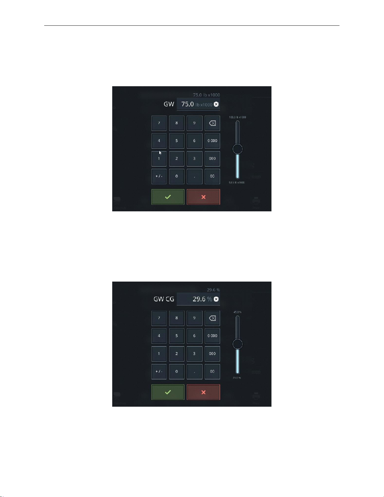
A320 Neo Instructor Operating Station
AIRCRAFT Tab
13 Oct 2017
Page 50
Instructor User Guide
8.2 GW Keypad
The GW keypad displays the current Gross Weight and allows the instructor to enter
another GW value either through the keypad or the slider.
8.3 GW CG Keypad
The GW CG keypad displays the current Gross Weight Center of Gravity (GW CG)
and allows the instructor to enter another GW CG value either through the keypad or
the slider.
Figure 26 GW Keypad
Figure 27 GW CG Keypad
Page 85
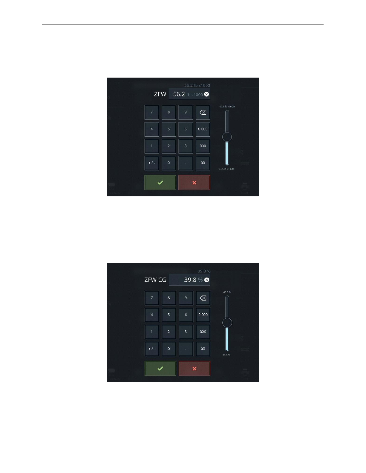
AIRCRAFT Tab
13 Oct 2017
Page 51
8.4 ZFW Keypad
The ZFW keypad displays the current Zero Fuel Weight (ZFW) and allows the
instructor to enter another ZFW value either through the keypad or the slider.
Instructor User Guide
AIRCRAFT Tab
8.5 ZFW CG Keypad
The ZFW CG keypad displays the current Zero Fuel Weight Center of Gravity (ZFW
CG) and allows the instructor to enter another ZFW CG value either through the
keypad or the slider.
Figure 28 ZFW Keypad
Figure 29 ZFW CG Keypad
Page 86
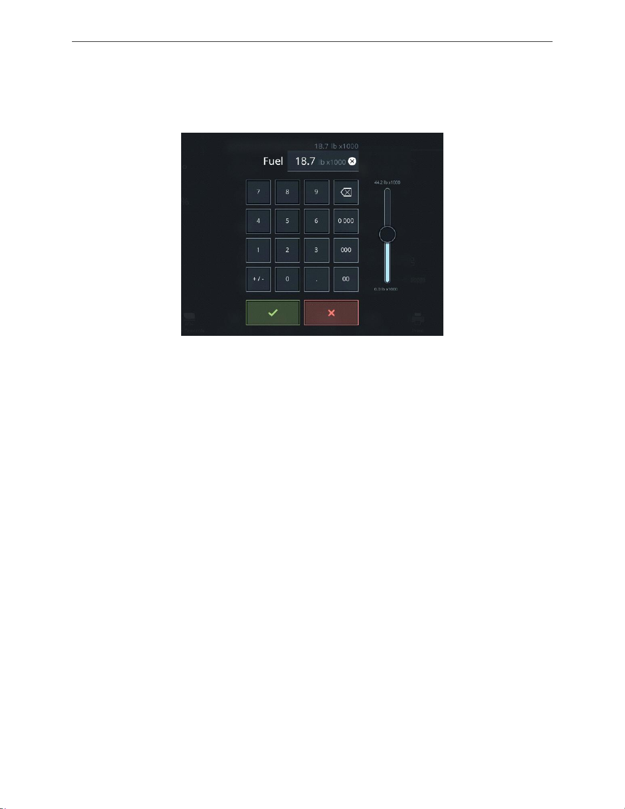
A320 Neo Instructor Operating Station
AIRCRAFT Tab
13 Oct 2017
Page 52
Instructor User Guide
8.6 Fuel Keypad
The Fuel keypad displays the current fuel weight and allows the instructor to enter
another fuel weight value either through the keypad or the slider.
8.7 Quick Access Buttons
The AIRCRAFT tab includes quick access buttons that upon tapping will display the
associated sliding panel.
8.7.1 DL
This button displays the Datalink (DL) status. When the datalink log has incoming
downlink messages from the crew, this button illuminates green.
Tap this button to display the DATALINK sliding panel.
8.7.2 UL
This button displays the Uplink (UL) status. When the datalink log has uplink
messages sent from instructor ground operation roleplay to crew, this button
illuminates orange.
Tap this button to display the DATALINK sliding panel.
Figure 30 Fuel Keypad
Page 87

AIRCRAFT Tab
13 Oct 2017
Page 53
8.7.3 VHF
This button displays:
• The status of the pilot and copilot radio communication.
• The radio transmission frequencies tuned by the pilot and copilot.
When a crew member speaks, green emitting waves are displayed next to pilot/copilot
icons.
Tap this button to display the COMMUNICATIONS sliding panel.
8.7.4 Weight &CG
Tap this button to display the WEIGHT & BALANCE sliding panel.
8.7.5 Services & Doors
Tap this button to display the SERVICES & DOORS sliding panel.
Instructor User Guide
AIRCRAFT Tab
8.7.6 Malfunctions
Tap this button to display the MALFUNCTIONS sliding panel. A red badge on this
quick access button indicates the number of active and armed malfunctions.
8.7.7 Circuit Breakers
Tap this button to display the CIRCUIT BREAKERS sliding panel. A red badge on
this quick access button indicates the number of circuit breakers that are
tripped/popped.
8.7.8 Fail Summary
Tap this button to display the FAIL SUMMARY sliding panel. A red badge on this
quick access button indicates the number failures included in the FAIL SUMMARY
sliding panel.
Page 88
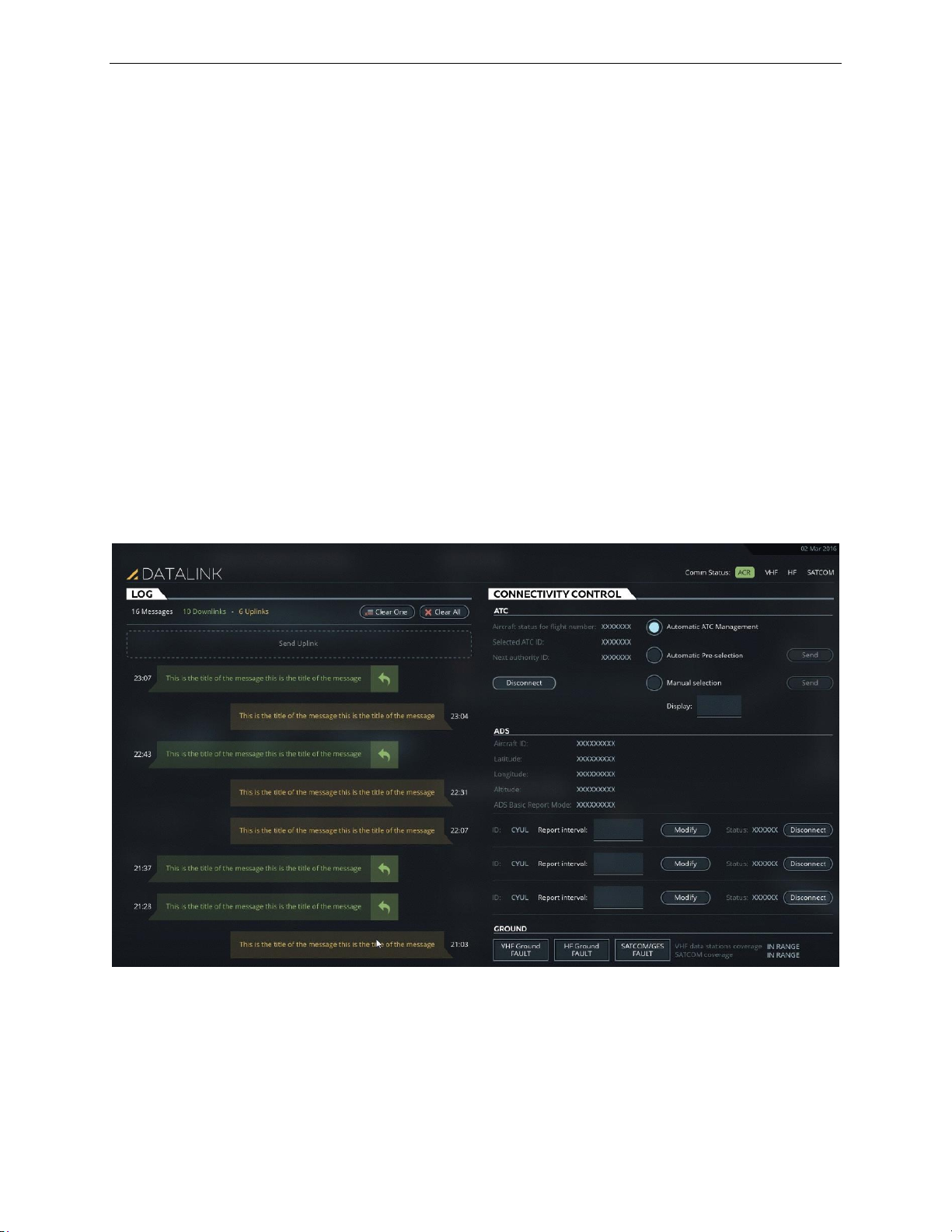
A320 Neo Instructor Operating Station
AIRCRAFT Tab
13 Oct 2017
Page 54
Instructor User Guide
8.8 DATALINK (DL/UL) Sliding Panel
The DATALINK sliding panel allows the instructor to:
• Uplink messages to the simulated aircraft
• Show communication between the simulated aircraft and the simulated ground
station
• Review and reply to messages from the simulated aircraft
• Control connections of:
o Air Traffic Controller (ATC)
o Automatic Dependent Surveillance (ADS)
• Trigger various ground station datalink failures
This sliding panel includes two tabs:
• LOG
• CONNECTIVITY CONTROL
Figure 31 DATALINK (DL/UL) Sliding Panel
Page 89

AIRCRAFT Tab
13 Oct 2017
Page 55
8.8.1 LOG Tab
Clear One
Tap this button to clear the oldest message from the log. The
oldest message is located at the bottom of the history log.
Clear All
Tap this button to clear all logged messages in the DATALINK
LOG Tab.
Send Uplink
Tap this message box to display the NEW UPLINK tab.
The LOG tab displays a history of communication between the simulated aircraft and
the simulated ground station, where the latest message is always displayed at the top
of the page.
This Tab includes the following buttons:
8.8.2 NEW UPLINK Tab
Instructor User Guide
AIRCRAFT Tab
The NEW UPLINK Tab allows the instructor to send uplink messages. This tab
includes the following sections:
• GROUPS
• SCENARIOS
• SCENARIOS
• Message Editor
8.8.2.1 GROUPS Section
This section lists all the various groups of scenarios for which uplink messages exist.
Tap on one of the GROUPS button to make your selection.
8.8.2.2 SCENARIOS Section
This section lists all the various uplink message categories within a selected group.
Tap on one of the scenarios button to view the available uplink messages for the
selected category.
8.8.2.3 SCENARIOS (Uplink Messages) Section
This section lists all the available uplink messages for the selected scenario (category)
8.8.2.3.1 Add Button
Tap the Add button next to an uplink message to add this uplink message into the
Message editor section.
Page 90
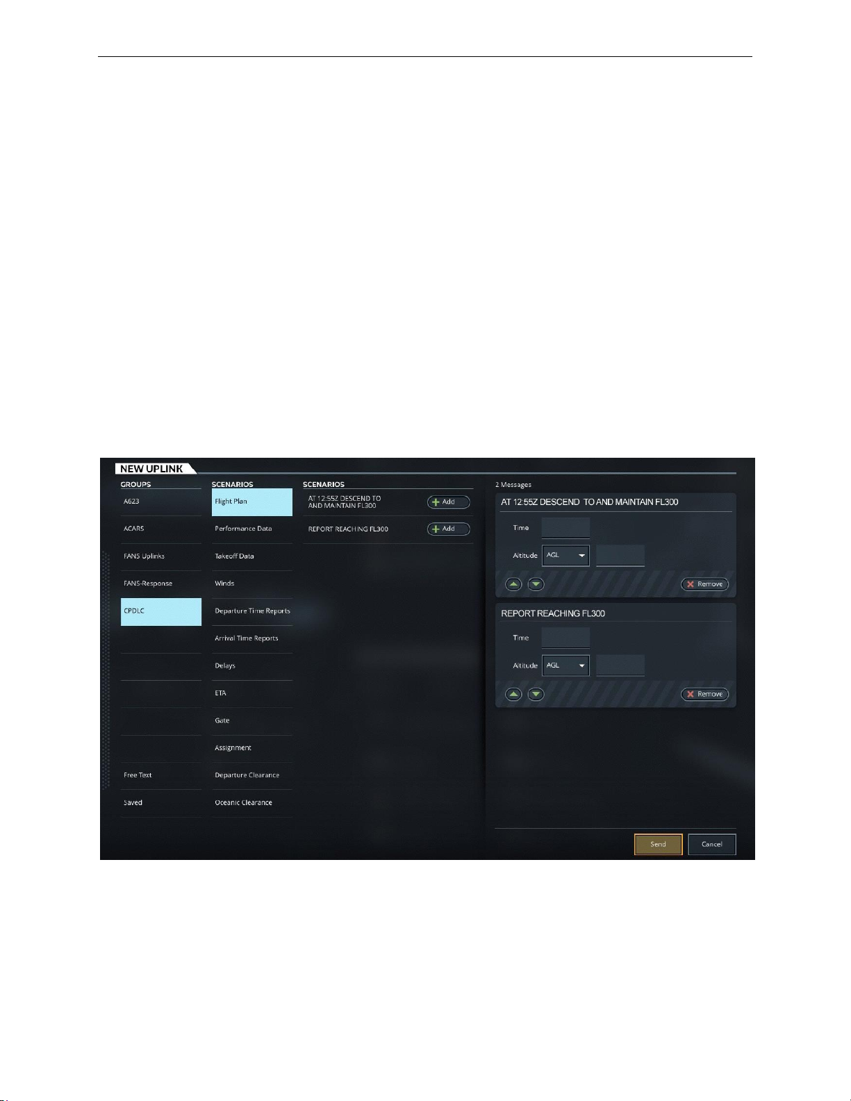
A320 Neo Instructor Operating Station
AIRCRAFT Tab
13 Oct 2017
Page 56
Instructor User Guide
8.8.2.4 Message Editor Section
This section shows the selected uplink messages and includes the controls to allow
the instructor to set parameters such as time and altitude as well as control the order
in which messages are sent to the crew.
8.8.2.4.1 Remove
Tap the Remove button within an uplink message, removes the uplink message from
the Message editor section.
8.8.2.4.2 ▲ and ▼ Buttons
Tap the ▲ and ▼ buttons to change the message priority within the Message Editor
section. The message priority within this box is the order in which messages will be
sent the crew.
Figure 32 NEW UPLINK Tab
Page 91
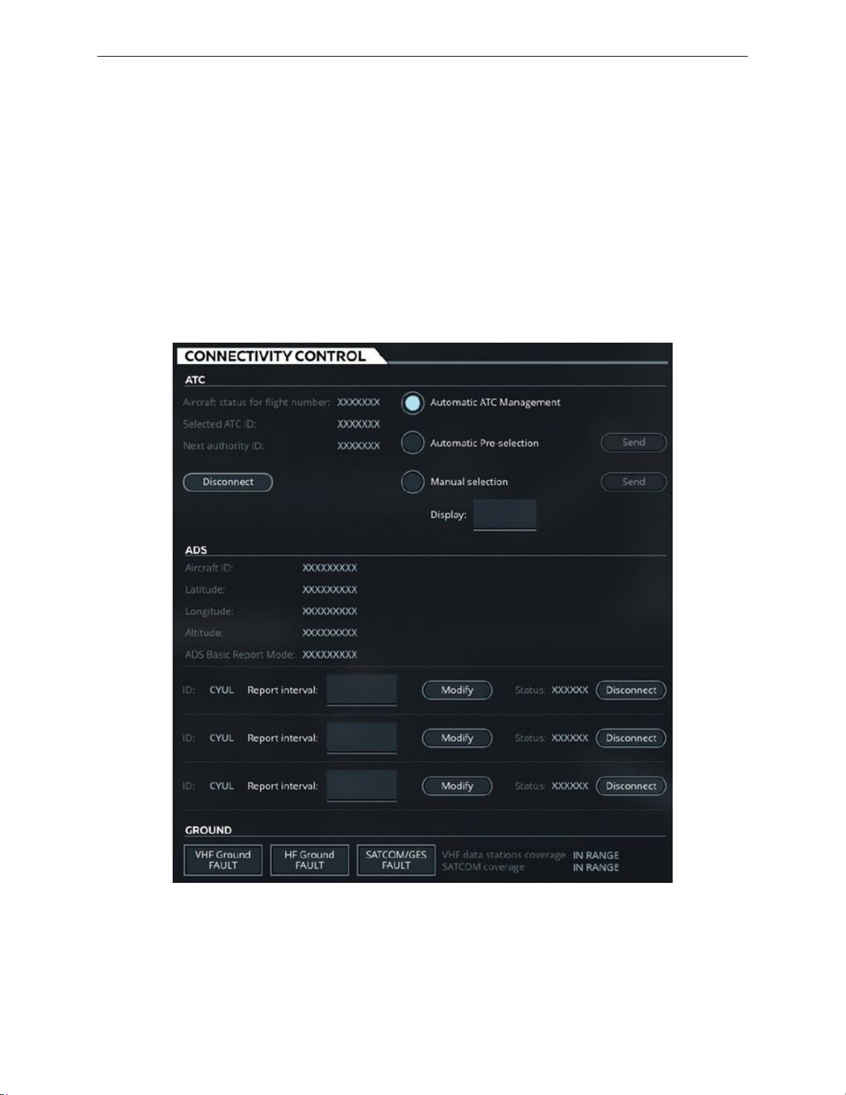
AIRCRAFT Tab
13 Oct 2017
Page 57
8.8.3 CONNECTIVITY CONTROL Tab
The CONNECTIVITY CONTROL Tab provides the controls to connect/disconnect
to ATC and ADS centers and displays Ground Communication status.
This tab includes the following sections:
• ATC
• ADS
• GROUND
Instructor User Guide
AIRCRAFT Tab
Figure 33 CONNECTIVITY Control Tab
Page 92
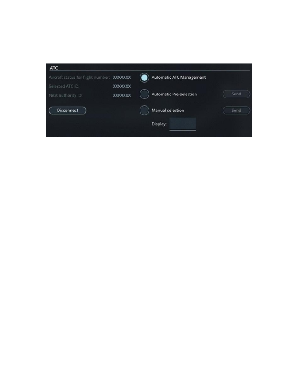
A320 Neo Instructor Operating Station
AIRCRAFT Tab
13 Oct 2017
Page 58
Automatic ATC Management
Tap this radio button to activate the Automatic
ATC Management mode. In this mode, the data
authority transfer is handled by the ground station
simulation which requires no action from the
instructor.
Automatic Pre-selection
Tap this button to activate the Automatic PreSelection mode. In this mode, the next data
authority is suggested by the software but the
transfer must be initiated by the instructor by
taping the Send button.
Manual Selection
Tap this button to activate the Manual Selection
mode. In this mode, the next data authority must
be selected by the instructor through the Display
input text field. Once the next data authority
selected, tap on the Send button to initiate the
transfer.
Instructor User Guide
8.8.3.1 ATC Section
This section mainly consists of ready only fields and radio buttons.
Figure 34 ATC Section
8.8.3.1.1 Read-Only Fields
The read-only fields display the current ATC connection flight number, active ATC
ID and Next authority ID.
8.8.3.1.2 Radio Buttons
There are three mutually exclusive radio buttons to select the next data authority.
Page 93
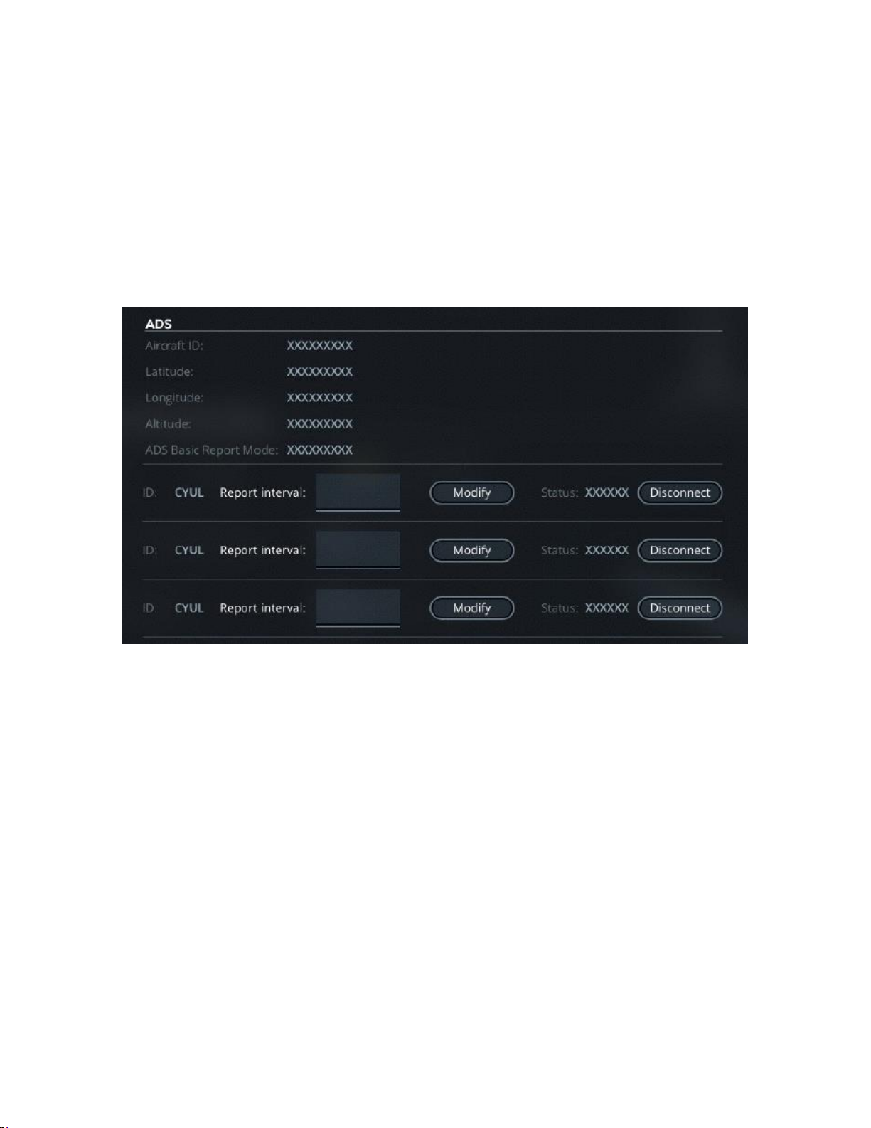
AIRCRAFT Tab
13 Oct 2017
Page 59
8.8.3.1.3 Disconnect
Tap this button to disconnect the current active ATC connection. Tapping this button
displays a pop menu to confirm the disconnect.
8.8.3.2 ADS Section
The Automatic Dependent Surveillance (ADS) section displays ADS information and
controls the ADS connections. This section includes read-only fields and a list of
ADS center IDs.
Instructor User Guide
AIRCRAFT Tab
8.8.3.2.1 Read-Only Fields
The read-only fields display the partial content of the last received ADS report.
• Aircraft ID
• Latitude
• Longitude
• Altitude
• ADS Basic Report Mode
Figure 35 ADS Tab
Page 94

A320 Neo Instructor Operating Station
AIRCRAFT Tab
13 Oct 2017
Page 60
ID
Displays the ADS Center ID.
Report Interval
Displays the ADS reporting interval.
Modify
Tap this button to modify the ADS reporting
interval.
Status
Displays the status of the ADS connection.
Connect/Disconnect
Tap this button to initiate the ADS connection or
the ADS disconnect.
Instructor User Guide
8.8.3.2.2 List of ADS Center IDs
This portion of the ADS section lists all the ADS Center IDs with associated controls.
8.8.3.3 GROUND Section
This section provides a status of ground communication and allows the instructor to
trigger communication failures. This section includes the following buttons.
8.8.3.3.1 VHF Ground FAULT
From the Normal state, tap this toggle fail button to trigger a datalink communication
failure with the VHF ground station.
From the Activated state, tap this toggle fail button to clear the failure and return to
the Normal state.
8.8.3.3.2 HF Ground FAULT
From the Normal state, tap this toggle fail button to trigger a datalink communication
failure with the HF ground station.
From the Activated state, tap this toggle fail button to clear the failure and return to
the Normal state.
8.8.3.3.3 SATCOM/GES FAULT
From the Normal state, tap this toggle fail button to trigger a datalink communication
failure with the SATCOM ground station.
From the Activated state, tap this toggle fail button to clear the failure and return to
the Normal state.
Page 95
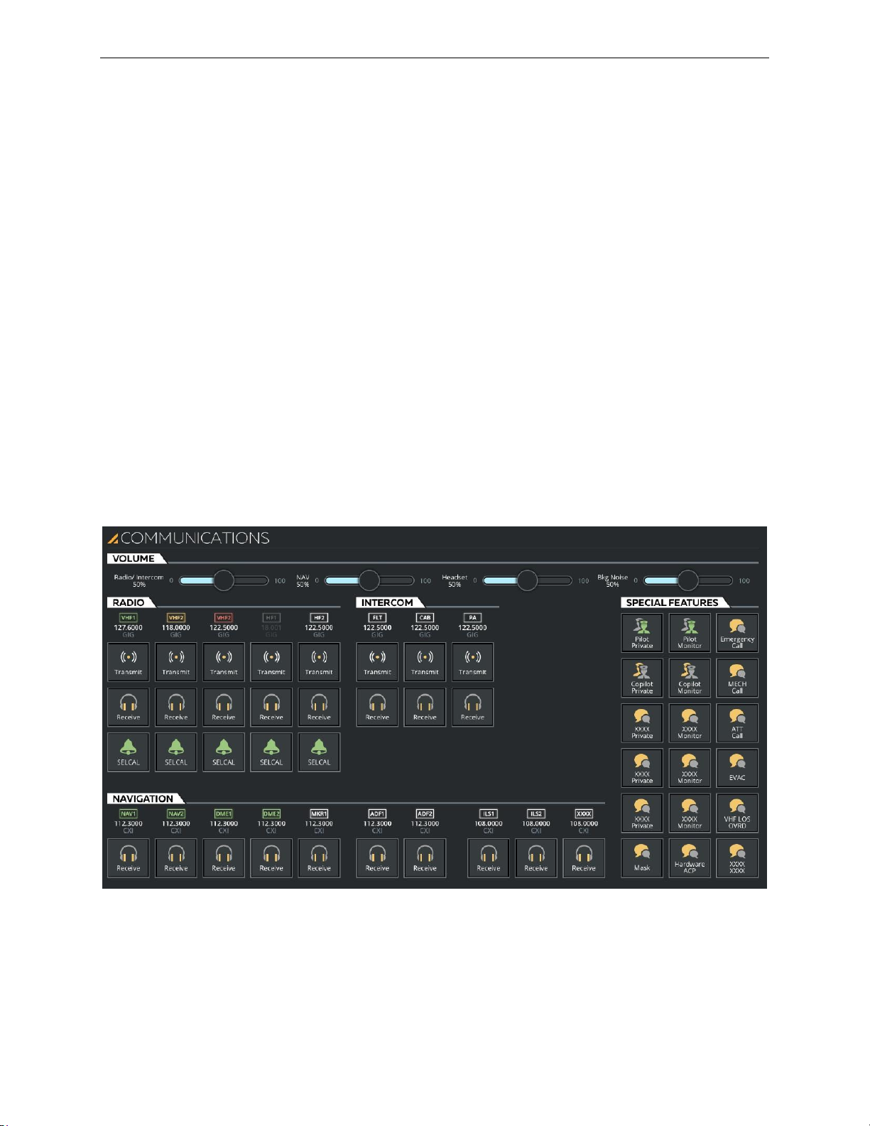
AIRCRAFT Tab
13 Oct 2017
Page 61
8.9 COMMUNICATIONS Sliding Panel
The COMMUNICATIONS sliding panel allows the instructor to:
• Establish:
o VHF and HF radio communications
o Communication with Inter Communication Systems (ICS)
• Listen to radio navigation signals
• Select various communication modes
This sliding panel provides controls to change any audio monitor, instructor transmit,
crew transmit or calls controls. It includes the following tabs:
• VOLUME
• RADIO
• INTERCOM
Instructor User Guide
AIRCRAFT Tab
• NAVIGATION
• SPECIAL FEATURES
Figure 36 COMMUNICATIONS Sliding Panel (Typical)
Page 96
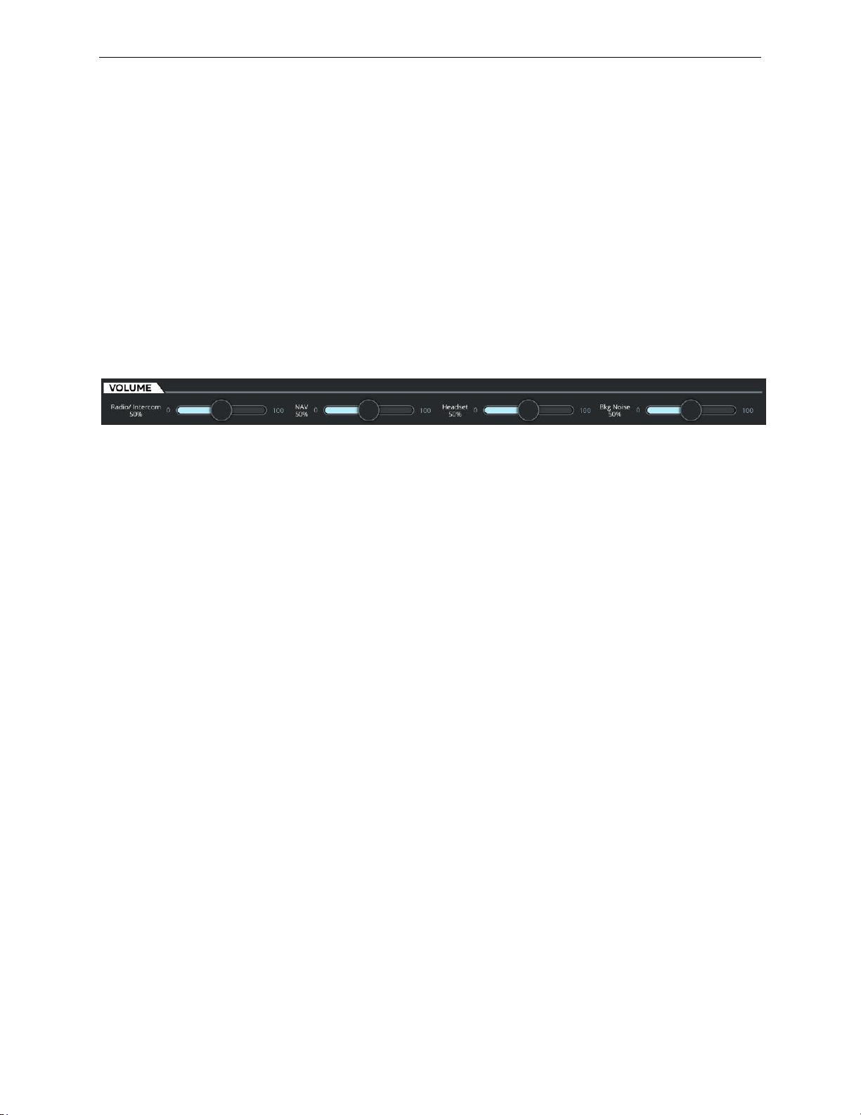
A320 Neo Instructor Operating Station
AIRCRAFT Tab
13 Oct 2017
Page 62
Transmit
Tap this button to transmit on the selected radio.
Receive
Tap this button to listen to selected channels or receivers.
SELCAL
Tap this button to initiate a SELCAL on the selected
transceiver or a call in the cockpit.
Instructor User Guide
8.9.1 VOLUME Tab
The VOLUME tab allows the instructor to control the volume level of audio signals
through slider controls. There are several sliders to control:
• Radio/Intercom headphone audio
• Navigation audio signal
• Headset audio
• Bkg Noise
Each volume sliding control can vary the volume from a minimum value to a
maximum value.
8.9.2 RADIO Tab
The RADIO tab allows the instructor to transmit on a selected VHF/HF radio, listen
to channels/receivers or initiate a selective call (SELCAL) to simulate a ground radio
station wishing to communicate the flight crew.
This tab displays all available VHF and HF radios.
Each of these radios is assigned a radio name and displays:
• The selected frequency and,
• The name of the tuned GND Station type
Each radio includes three buttons:
Figure 37 VOLUME Tab (Typical)
Page 97
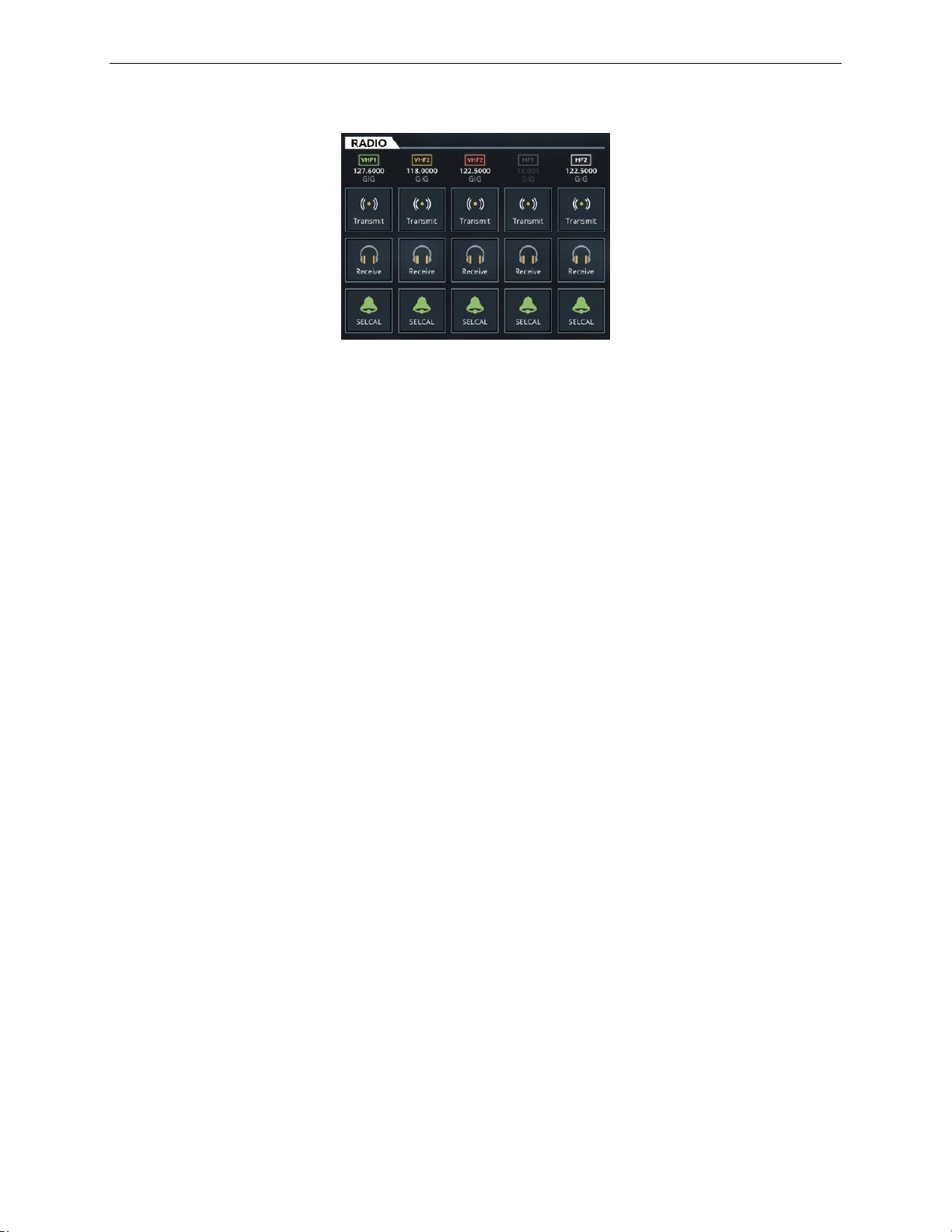
AIRCRAFT Tab
13 Oct 2017
Page 63
8.9.3 INTERCOM Tab
Intercom Call Incoming Info
Intercom Name
Transmit
Tap this button to allow the instructor to transmit on
the selected ICS. This button is disabled if there is
no power on a specific radio transmitter.
Receive
Tap this button to allow the instructor to listen on the
selected ICS.
The INTERCOM tab allows the instructor to communicate with Inter Communication
Systems (ICS) such as:
Instructor User Guide
AIRCRAFT Tab
Figure 38 RADIO Tab
• Flight Deck (FLT)
• Cabin (CAB)
• Passenger Address (PA)
Each of the ICS includes:
8.9.4 NAVIGATION Tab
The NAVIGATION tab allows the instructor to listen to the signal of navigation
systems such as:
• Navigation (NAV)
• Distance Measuring Equipment (DME)
• Marker Beacon
• Automatic Direction Finder (ADF)
• Instrument Landing System (ILS)
Page 98

A320 Neo Instructor Operating Station
AIRCRAFT Tab
13 Oct 2017
Page 64
Instructor User Guide
Listening to a navigation receiver consists of selecting the relevant Receive button.
Each navigation receiver includes Navigation:
• Receiver name
• Tuned-in frequency
• Receiver station name
8.9.4.1 Receive
Tap the Receive button of the desired navigation radio to listen to the radio signal and
monitor the navigation receiver.
8.9.5 SPECIAL FEATURES Tab
The SPECIAL FEATURES tab allows the instructor to select various communication
modes such as private communication and communication monitoring as well as
other various types of calls.
8.9.5.1 Pilot Private
Tap this button to establish a private communication between the instructor and the
Pilot.
8.9.5.2 Copilot Private
Tap this button to establish a private communication between the instructor and the
Copilot.
8.9.5.3 Pilot Monitoring
Tap this button to monitor Pilot communications.
8.9.5.4 Copilot Monitor
Tap this button to monitor Co-pilot communications.
8.9.5.5 Emergency Call
Tap this button to simulate the instructor placing an emergency call in the cockpit.
8.9.5.6 MECH Call
Tap this button to simulate the instructor making a call from a mechanic (MECH) to
the cockpit crew.
Page 99

AIRCRAFT Tab
13 Oct 2017
Page 65
8.9.5.7 ATT Call
Tap this button to simulate the instructor making a call from an attendant (ATT) to
the cockpit crew.
8.9.5.8 EVAC
Tap this button to have the instructor trigger an EVACuation attention getter in the
cockpit.
8.9.5.9 Mask
Tap this button to activate the microphone in the instructor mask during cockpit
smoke simulation.
8.9.5.10 Hardware ACP
Tap this toggle button to activate/deactivate the Instructor Station Audio Control
Panel (ACP).
8.9.5.11 VHF LOS OVRD
Instructor User Guide
AIRCRAFT Tab
Tap this button to allow communication irrespective of the aircraft LOS to the tuned
ground station or propagation degradation.
When selected, the instructor VHF radios are considered on-board as per the cockpit
crew’s VHF radios.
When deselected, the distance and elevation of the simulated aircraft with respect to
the tuned ground station are computed to realistically simulate air-to-ground
communication.
Page 100
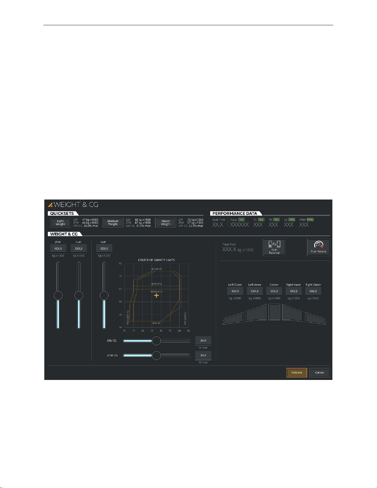
A320 Neo Instructor Operating Station
AIRCRAFT Tab
13 Oct 2017
Page 66
Instructor User Guide
8.10 WEIGHT & BALANCE Sliding Panel
The WEIGHT & BALANCE sliding panel allows the instructor to quickly configure
the weight of the aircraft. It includes all the necessary controls to quickly:
• Set the aircraft to predefined weights
• Adjust the Zero Fuel Weight
• Adjust the fuel weight
• Manage the fuel weight of each fuel tank
This sliding panel includes three main tabs:
• QUICKSETS
• PERFORMANCE DATA
• WEIGHT & CG
Figure 39 WEIGHT & BALANCE Sliding Panel
 Loading...