How it Works
Log In / Sign Up
Buy Points
How it Works
FAQ
Contact Us
Questions and Suggestions
Users
Frymaster
Loading...
S
SinBaD Series
Single Under Fryer Filter
Single Under Fryer Filter (SUFF)
SM20
SM20G
SM220
2
SM220G
SM40
SM40G
SM50
SM5020G
SM50G
2
SM60
SM60G
SM80
SM80G
Sprigfield Gas Range
SR114E
2
SR14E
SR38
2
SR38E
2
SR38G
SR42
2
SR42G
SR42 Series
SR52
SR52G
2
SR52 Series
SR62
SR62G
2
SR62 Series
SUFF
SUFF 50
2
SUFF 60
SUFF 80
Super Cascade 75
Super Cascade Filtration Systems CE
Super Marathon Series
Super Runner
2
Super Runner Series
T
TB14
2
TB14 Series
TC25
TCF
ThermoGlo
TRITON FE155
U
UFF
UFF 60
UFF 85
UHC
2
UHC-HD
6
UHC-MCDONALDS
2
UHC-P
8
UHC-P 2
UHC-P 2-yuva
UHC-P 4
UHC-P 4-yuva
2
UHC-PN
2
Ultimate Electric Series
Under Fryer Filter
Under Fryer Filter (UFF)
Universal Holding Cabinet
2
V
VALUE 14-17
2
VT
6
VT Series
Y
YFG255
3
YFPRE
2
YFPRE1817E
YFPRE18E
YFPRE SERIES
Y-KSCF-C-HC18G
YPF95
2
YPF95 Series
YSCF14G
YSCF14G Series
YSCF214G
YSCFC 1824G
YSCFC24
YSCFC2424G
3
YSCFC24GSERIES YSCFC24GSERIES
YSCFC24 Series
YSCFH214GCNS
2
YSCFH314GNC
YSCFHC18G
3
YSM80
YUM
Loading...
Loading...
Nothing found
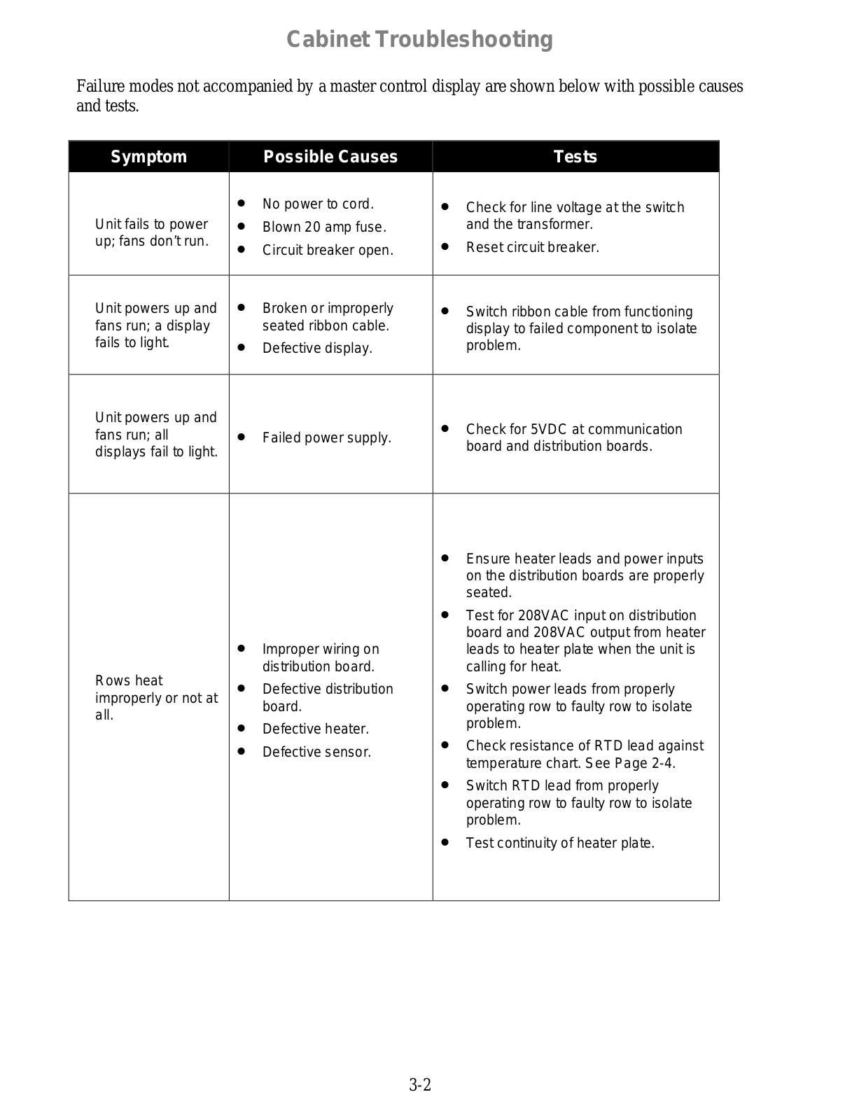
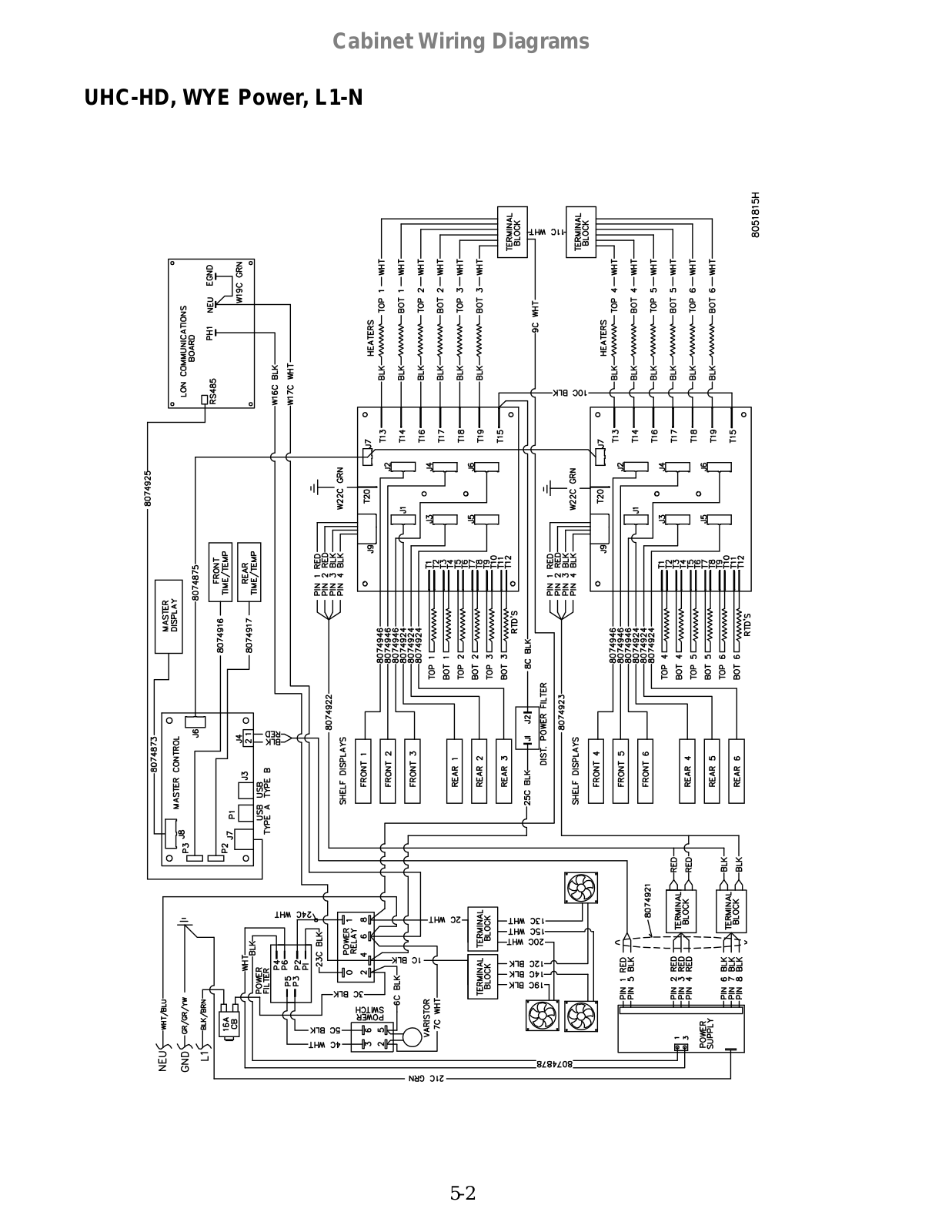
UHC-HD
Operators Manual
30 pgs
1.56 Mb
0
Owner’s Manual
24 pgs
1.2 Mb
0
Parts List
4 pgs
108.73 Kb
0
Service & Parts Manual
24 pgs
1.36 Mb
0
User Manual
24 pgs
1.35 Mb
0
User Manual
3 pgs
370.41 Kb
0
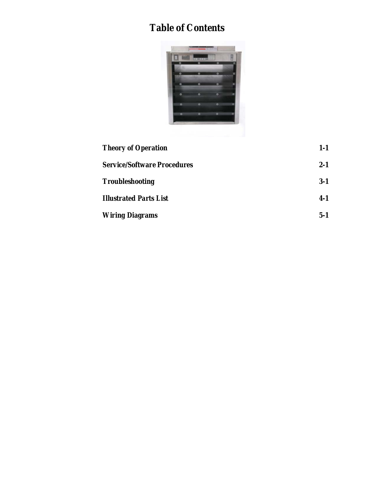
Table of contents
Loading...
Frymaster UHC-HD User Manual
...
Frymaster User Manual
Download
Specifications and Main Features
Frequently Asked Questions
User Manual
Download
Loading...
+
hidden pages
Unhide
You need points to download manuals.
1 point = 1 manual.
You can buy points or you can get point for every manual you upload.
Buy points
Upload your manuals
 Loading...