

Page 1
Super Runner Series Electric Fryers
Service & Parts Manual
Super Runner Electric Series
SR114E
NON-CE &
Dean, a member of the Commercial Food Equipment Service Association, recommends using
CFESA Certified Technicians.
24-Hour Service Hotline 1-800-551-8633
*8196109*
10/2015
Page 2
NOTICE
IF, DURING THE WARRANTY PERIOD, THE CUSTOMER USES A PART FOR THIS ENODIS
EQUIPMENT OTHER THAN AN UNMODIFIED NEW OR RECYCLED PART PURCHASED
DIRECTLY FROM FRYMASTER DEAN, OR ANY OF ITS AUTHORIZED SERVICE CENTERS,
AND/OR THE PART BEING USED IS MODIFIED FROM ITS ORIGINAL CONFIGURATION, THIS
WARRANTY WILL BE VOID. FURTHER, FRYMASTER DEAN AND ITS AFFILIATES WILL NOT BE
LIABLE FOR ANY CLAIMS, DAMAGES OR EXPENSES INCURRED BY THE CUST OMER WHICH
ARISE DIRECTLY OR INDIRECTLY, IN WHOLE OR IN PART, DUE TO THE INSTALLATION OF
ANY MODIFIED PART AND/OR PART RECEIVED FROM AN UNAUTHORIZED SERVICE CENTER.
DANGER
Copper wire suitable for at least 167°F (75°C) must be used for power connections.
DANGER
The electrical power supply for this appliance must be the same as indicated on the
rating and serial number plate located on the inside of the fryer door.
DANGER
This appliance must be connected to the voltage and phase as specified on the rating
and serial number plate located on the inside of the fryer door.
DANGER
All wiring connections for this appliance must be made in accordance with the wiring
diagrams furnished with the equipment. Wiring diagrams are located on the inside of
the fryer door.
DANGER
Do not store or use gasoline or other flammable vapors and liquids in the vicinity of this
or any other appliance.
WARNING
Do not attach accessories to this fryer unless fryer is secured from tipping. Personal
injury may result.
WARNING
Frymaster Dean fryers equipped with legs are for permanent installations. Fryers fitted
with legs must be lifted during movement to avoid damage and possible bodily injury.
For a moveable or portable installation, Frymaster optional equipment casters must be
used.
Questions? Call 1-800-551-8633
WARNING
Do not use water jets to clean this equipment.
DANGER
All wiring connections for this appliance must be made in accordance with the wiring
diagrams furnished with the equipment. Wiring diagrams are located on the inside of
the fryer door.
WARNING
This equipment is intended for indoor use only. Do not install or operate this
equipment in outdoor areas.
ii
Page 3

Super Runner Series Electric Fryers
TABLE OF CONTENTS
Page
CAUTIONARY STATEMENTS ii
ELECTRICAL POWER SPECIFICATIONS iv
CHAPTER 1 – SERVICE PROCEDURES 1-1
1.1 General 1-1
1.2 Calibrating the Temperature Control Knob 1-1
1.3 Accessing the Control Box Electronics 1-2
1.4 Replacing a Temperature Control Board 1-2
1.5 Replacing a Transformer, Contactor or Relay 1-2
1.6 Replacing a Power Switch or Indicator Lamp 1-3
1.7 Replacing a Temperature Probe or High-Limit Thermostat 1-3
1.8 Replacing a Heating Element 1-4
1.9 Replacing a Frypot 1-4
1.10 Probe Resistance Chart 1-5
1.11 Troubleshooting Guides 1-5
1.12 Wiring Diagrams 1-7
CHAPTER 2 – PARTS LIST 2-1
2.1 Accessories 2-1
2.2 Cabinetry 2-2
2.3 Control Box 2-5
2.4 Electronics Components, Elements and Cable 2-6
iii
Page 4
A
ELECTRICAL POWER SPECIFICATIONS
Use copper wire ONLY, suitable for at least 170F (75C)
MODEL VOLTAGE PHASE
14 kW 208 Single 3 3 (5.83) 68
14 kW 208 3 3 6 (4.11) 39
14 kW 240 Single 3 4 (5.19) 59
14 kW 240 3 3 8 (3.26) 34
14kW 230/400 3 4 6 (4.11) 21
WIRE
SERVICE
MINIMUM WIRE
SIZE
WG mm
AMPS
(per
leg)
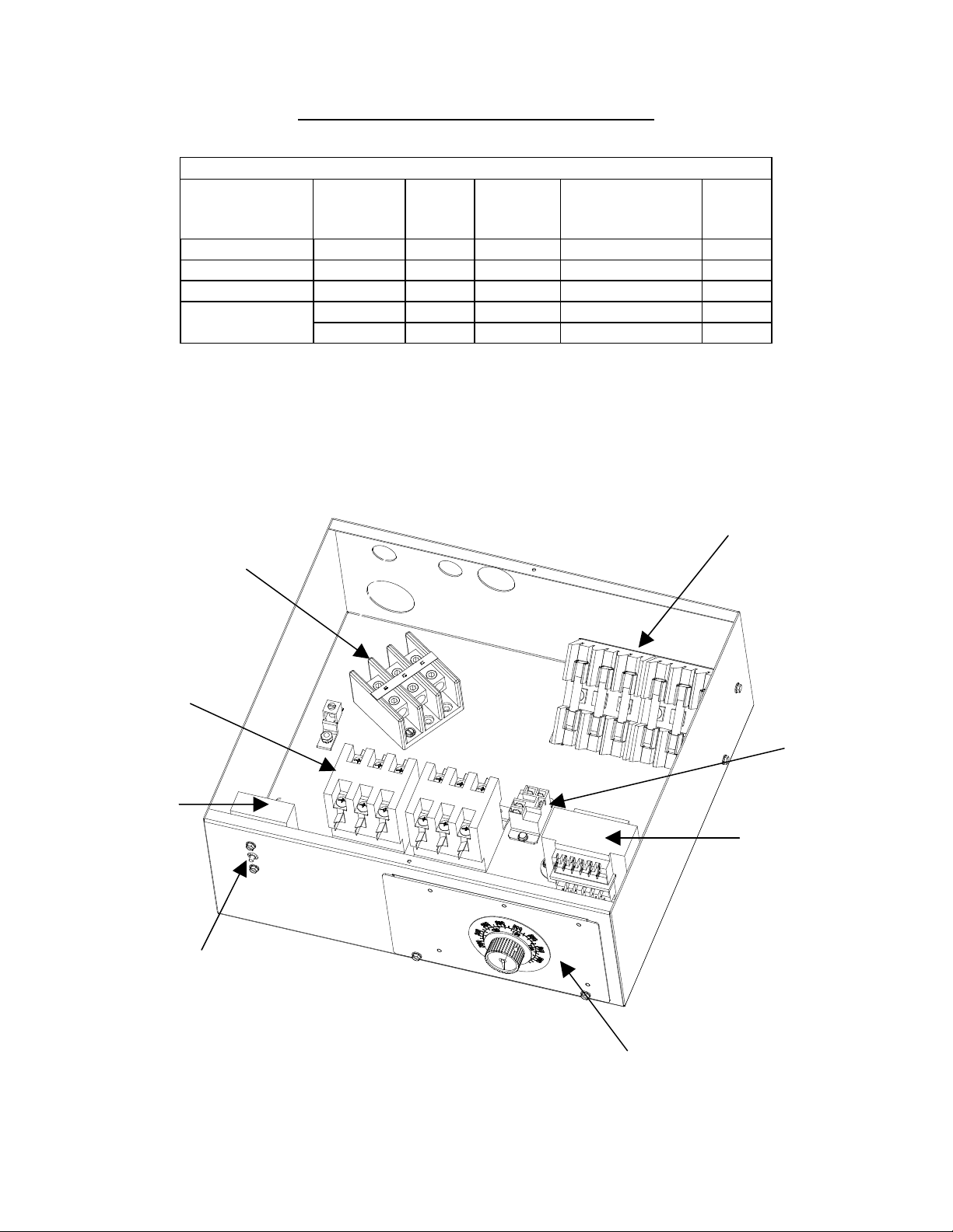
Interior View of the Control Box
Contactors
High-Limit
Terminal
Block
Fuse Block
Relay
Transformer
High-Limit Reset
Switch
Single Phase Control Box Shown
Note: The three phase control box
differs from the single phase by
eliminating the fuse block and terminal
block.
iv
Controller
Assembly
Page 5
SUPER RUNNER SERIES ELECTRIC FRYERS
CHAPTER 1: SERVICE PROCEDURES
1.1 General
Before performing any maintenance on your Dean Super Runner Electric fryer, you must disconnect
the electrical power supply.
When electrical wires are disconnected, it is recommended that they be marked in such a way as to
facilitate re-assembly.
DANGER
Hot oil will cause severe burns. Never attempt to move this appliance when filled with hot
oil, or to transfer hot oil from one container to another.
DANGER
This equipment should be unplugged when servicing, except when electrical circuit tests are
required. Use extreme care when performing such tests.
Disconnect all power cords before servicing.
Inspection, testing and repair of electrical components should be performed by an
authorized service agent only.
1.2 Temperature Control Knob Calibration
If the temperature controller knob requires adjustment, do the following:
1. Set the temperature controller dial to the desired oil temperature and wait for the temperature to
stabilize.
2. When the oil temperature reaches operating temperature, let the heating elements cycle at least
four times (indicated by the HEAT light going out and coming back on).
3. Insert a thermometer or pyrometer probe near the temperature-sensing probe approximately three
inches deep into the oil. When the heating elements cycle on for the fourth time, the temperature
should read within 5F ( 3C) of the temperature control knob setting.
4. Loosen the knob setscrew and rotate the knob to the correct temperature setting on the faceplate.
5. Check the temperature again with a high-quality immersion thermometer to confirm that the
setting is correct.
6. Re-tighten the knob setscrew at the calibrated position.
1-1
Page 6

1.3 Accessing the Control Box Electronics
(Transformer, Contactor and Relay)
1. Unplug the power cord.
2. Open front door of cabinet and remove the two screws from the top of the control box cover to
remove the cover.
1.4 Replacing a Temperature Control Board
1. Unplug the power cord. Perform Procedure 1.3, Steps 1-2, Accessing the Control Box
Electronics.
2. Remove the 2 screws from the bottom of the controller faceplate.
3. Remove the setscrew from the controller knob.
4. Unplug the connector from the controller board.
5. Remove the nuts from each stud on the control board and slide the board from the studs. Ensure
that standoffs remain in place on studs, prior to installing new board. Install the new board by
reversing the previous procedures.
6. Perform Procedure 1.2 to recalibrate the temperature control knob.
1.5 Replacing a Transformer, Contactor or Relay
1. Unplug the power cord. Perform Procedure 1.3, Steps 1-2, Accessing the Control Box
Electronics.
2. Remove all wiring from the terminals of the transformer, contactor or relay to be replaced,
ensuring that each wire is marked for reattachment.
3. Remove the screws that secure the transformer, contactor or relay to the control box.
4. Install the new transformer, contactor or relay by reversing the preceding procedures. Make sure
you reconnect the wiring to the proper terminals.
1-2
Page 7

1.6 Replacing a Power Switch or Indicator Lamp
1. Unplug the power cord.
2. Remove the two screws on the bottom of the faceplate. Pull out and lift up slowly. Note that
when lowering the faceplate, the door will lower and swing out to be set aside.
3. Mark wires for reattachment as you disconnect them.
4. Remove the old switch or lamp.
5. Install new switch or lamp and reassemble in reverse order.
1.7 Replacing a Temperature Probe or High-Limit Thermostat
1. Unplug the power cord.
2. Drain the cooking oil from the frypot and leave the drain open.
3. Remove the two screws from the top control box cover.
4. Remove the screws from the back fryer cover.
5. If replacing the temperature probe, disconnect the wire plug containing the probe wiring.
6. Using an open end wrench, loosen the temperature probe or high-limit probe. Pull the probe
through the hole and remove the probe.
7. If replacing the high-limit thermostat, remove the two screws that attach the high-limit reset
switch to the control box. Remove the two wires attached to the high-limit reset switch. Pull the
probe through the bushing in the rear of the control box. Attach new high-limit reset switch to
the control box and reattach wires. Thread through the bushing in the rear of the control box.
8. Thread the new probe through the proper hole in the rear of the frypot. Ensure that the probe is
aligned with the holes on the bracket attached to the element.
9. Apply Loctite PST567 sealant to replacement threads.
10. Screw the replacement probe into the frypot and tighten 170-180 inch-pounds torque. DO NOT
OVERTIGHTEN.
11. Reattach the connector and reassemble in reverse order.
1-3
Page 8

1.8 Replacing a Heating Element
1. Perform Procedure 1.7, Replace Temperature Probe, Steps 1-4.
2. Mark wires of the elements before disconnecting from the contactor to facilitate easy
reassembly. Pull the wires through the conduit.
3. Remove element using an open-end wrench or other suitable tool to loosen the compression
fitting.
4. Gently remove the element by sliding out into the frypot and lifting up as you remove it.
5. Insert new element and reassemble in reverse order. Ensure that the element wires are correctly
attached to the contactor.
1.9 Replacing a Frypot
1. Perform Procedure 1.3, Accessing the Control Box Electronics, Steps 1-2.
2. Perform Procedure 1.7, Replacing a Temperature Probe, Steps 1-7.
3. Perform Procedure 1.8, Replacing a Heating Element, Steps 1-4.
4. Remove the screws holding the fluecap to the side panels.
5. Remove the screws attaching the faceplate bracket and heatshield to the front of the frypot
6. Remove the screws securing the frypot to the front frame of the fryer.
7. Carefully lift the frypot from the cabinet.
8. Remove the drain valve from the old frypot and install on the new frypot.
9. Apply Loctite Sealant PST 567 to the high-limit threads, temperature probe threads and element
threads. Install high-limit, temperature probe and elements into the new frypot.
10. Follow the preceding steps in reverse to install the new frypot into the fryer.
1-4
Page 9

1.10 Probe Resistance Chart
b
Use the chart below when testing temperature probes and probe circuits for proper operation.
Probe Resistance Chart
F OHMS C F OHMS C F OHMS C F OHMS C F OHMS C
60 1059 16 130 1204 54 200 1350 93 270 1493 132 340 1634 171
65 1070 18 135 1216 57 205 1361 96 275 1503 135 345 1644 174
70 1080 21 140 1226 60 210 1371 99 280 1514 138 350 1654 177
75 1091 24 145 1237 63 215 1381 102 285 1524 141 355 1664 179
80 1101 27 150 1247 66 220 1391 104 290 1534 143 360 1674 182
85 1112 29 155 1258 68 225 1402 107 295 1544 146 365 1684 185
90 1122 32 160 1268 71 230 1412 110 300 1554 149 370 1694 188
95 1133 35 165 1278 74 235 1422 113 305 1564 152 375 1704 191
100 1143 38 170 1289 77 240 1432 116 310 1574 154 380 1714 193
105 1154 41 175 1299 79 245 1442 118 315 1584 157 385 1724 196
110 1164 43 180 1309 82 250 1453 121 320 1594 160 390 1734 199
115 1174 46 185 1320 85 255 1463 124 325 1604 163 395 1744 202
120 1185 49 190 1330 88 260 1473 127 330 1614 166 400 1754 204
125 1195 52 195 1340 91 265 1483 129 335 1624 168 405 1764 207
1.11 Troubleshooting
1.11.1 Control and Heating Problems
Problem Probable Causes Corrective Action
A. Power cord is not plugged in or circuit
breaker is tripped.
B. Controller has failed.
Controller won't
activate.
C. Power supply component or
temperature control board has failed.
Fryer heat cycles on
and off during warm
up cycle.
Fryer does not heat.
A. Fryer in melt cycle.
B. Controller has failed.
A. Plug power cord in and verify that
the circuit breaker is not tripped.
B. If available, substitute a controller
known to be working for the
suspect controller. If the substitute
controller functions correctly, order
a new controller from a FASC.
C. If any of the components in the
power supply system (including the
transformer and temperature control
oard) fail, power will not be
supplied to the controller and it will
not function.
A. This is normal behavior while the
fryer temperature is below 180ºF
(82ºC).
B. If available, substitute a controller
known to be working for the
suspect controller. If the substitute
controller functions correctly, order
a new controller from a FASC.
(continued on following page)
1-5
Page 10

Problem Probable Causes Corrective Action
Fryer does not heat.
Fryer heats until high-
limit trips with heat
indicator ON.
Fryer heats until high-
limit trips with heat
indicator OFF.
Fryer stops heating
with heat indicator
ON.
C. One or more other components have
failed.
Temperature probe or controller has
failed.
Contactor, controller or element has
failed
The high-limit thermostat or contactor
has failed.
C. If the circuitry in the fryer control
system cannot determine the frypot
temperature, the system will not
allow the element to be energized
or will de-energize the element if it
is already energized. If the
contactor, element, or associated
wiring fails, the element will not
energize.
If available, substitute a controller
known to be working for the suspect
controller. If the substitute controller
functions correctly, order a new
controller from FASC. If substitution
of the controller does not resolve the
problem, the most likely cause is a
failed temperature probe.
If available, substitute a controller
known to be working for the suspect
controller. If the substitute controller
functions correctly, order a new
controller from FASC. If the
substitution of the controller does not
resolve the problem, the most likely
cause is a contactor that has failed in
the closed position or a bad element.
The fact that the heat indicator is ON
indicates that the controller is
functioning properly and is calling for
heat. The high-limit thermostat
functions as a normally closed switch.
If the thermostat fails, the "switch"
opens and power to the elements is
shut off. If the contactor fails to close,
no power is supplied to the elements.
1-6
Page 11

1.12.1 Wiring Diagram SR114E Single Phase
1-7
Page 12

1.12.2 Wiring Diagram SR114E 3 Phase
1-8
Page 13

1.12.3 Wiring Diagram SR114E WYE
1-9
Page 14

SUPER RUNNER SERIES ELECTRIC FRYERS
2.1 Accessories
CHAPTER 2: PARTS LIST
1
5
Item Part Number Description
1 803-0197 Fryer Friend 27” (Cleanout Rod)
2 803-0209 Brush, Frypot Cleaning
3 809-0171 Thumbscrew, ¼-20 X 1⅜-inch Basket Hanger
4 810-2793 Hanger, Basket
5 803-0019 Basket, Twin
6 803-0132 Basket Support Rack, Full Vat
7 826-0900 Kit, Chain Restraint for Casters
8 826-1095 Kit, Anchor Strap for Legs
2
6
3
4
7 8
2-1
Page 15

2.2 Cabinetry
2.2.1 Back, Base, Casters, Sides, Fluecap, Top Cap and Frypot
11
12
14
15
10
13
4
1
3
8
6
7
9
5
2
16
17
18
2-2
Page 16

Item
1
2
3
4
5
6
7
8
9
10
11
12
13
14
15
16
*
*
*
17
*
*
*
18
*
*
*
* Not Illustrated
Part Number Description
106-3528 Cabinet Assembly, Economy Electric SR114E
106-4419 Assembly, Heat Shield
200-5998 Channel, Base
200-8378 Brace, Cabinet Front
201-5802 Side, Cabinet Left
202-5802 Side, Cabinet Right
809-0117 Screw, 10-32 x 3/8 SLTD TR HD SS
809-0256 Nut, KEPS 10-32 HX ZP
809-0412 Screw, #10 – ½ HX HD
200-5810 Back, Cabinet
210-8401 Panel, Front
210-5803 Fluecap
106-4423 Frypot Assembly
810-1338 Valve, 1” Universal Ball
810-1567 Handle, Drain Valve Red w/ Lock Pin
812-1227 Nipple, Drain 1”
810-0356 Caster, 5” Wheel w/o Brake
826-2003 Mounting Hardware SR114E Casters
809-0428 Screw, ¼-20x ½ Hex Head ZP
809-0071 Nut, ¼-20 HX ZP
809-0191 Washer, Lock ¼ Spring ZP
810-0357 Caster, 5” Wheel w/ Brake
826-2003 Mounting Hardware SR114E Casters
809-0428 Screw, ¼-20x ½ Hex Head ZP
809-0071 Nut, ¼-20 HX ZP
809-0191 Washer, Lock ¼ Spring ZP
826-1903 Leg Accessory Pack, Includes 810-2053 and hardware below
810-2053 Leg, Black Adjustable w/Mount Plate
809-0131 Screw, ¼-20x ¾ Hex Head ZP
809-0071 Nut, ¼-20 Hex ZP
809-0191 Washer, Lock ¼ Spring ZP
2-3
Page 17

2.2.2 Door Assembly and Component Parts
6
9
10
11
2
7
4
3
1
8
Item Part Number Description
106-3586 Door Assembly
1 106-4067 Pin Assembly, Door
809-0216 Pin, Hinge Cover & Door
810-0658 Retaining Ring (Unplated)
2 210-9491 Panel, Door
3 210-9544 Bracket, Door Hinge
4 809-0083 Rivet, Pop Al 1/8” Dia
5 809-0193 Washer, Flat ¼” Nylon
6 809-0266 Screw, #10-½” Phil TR Head ZP
7 810-0066 Catch, Magnetic Door
8 810-0275 Spring, Door Hinge
9 810-1422 Handle, Door
10 816-0529 Bumper, Rubber Self Adhesive
11 816-0630 Cap, Vinyl 172 x .500
5
2-4
Page 18

2.3 Control Boxes
6
11
2
2
4
10
3
15
13
7
5
9
1716
8
1
5
14
12
9
1716
3-Phase Control Box Single Phase Control Box
Item Part Number Description
106-3747 Control Box Assembly, Single Phase
106-3583 Control Box Assembly, 3 Phase
1 106-3748 Controller Assembly
802-2198 Label, Thermatron Dial
810-0387 Control Knob
2 200-8240 Box, Control
3 200-8369 Mount, Fuse Economy
4 807-0065 Block, Terminal Field
5 807-0070 Terminal Ground Lug
6 807-0501 Fuse Block, Buss #2968 3-Pole
7 807-1683 Relay, 12 VDC
8 807-5129 Transformer, V&T Dual Voltage, 208/222/230/240V
9 807-3559 High-Limit, 435°F w/ Manual Reset
* 807-3560 High-Limit, 410°F (210°C) w/Manual Reset (CE)
10 807-4017 Fuse, 50 AMP 480VAC, 300VDC
11 809-0112 Screw, 8-32 x 1 ¼ TR SL HD SS
12 809-0117 Screw, 10-32 x 3/8 SLTD TR HD SS
13 809-0247 Nut, 8-32 HEX KEPS ZP
14 809-0256 Nut, KEPS 10-32 HX ZP
15 809-0359 Screw, #8 x ¼ HX HD Washer Slotted HD ZP
16 809-0361 Screw, Drill #8 x ½ HX HD ZP
17 810-1202 Contactor, 3 Pole 600V 40 AMP
* 200-8241 Cover, Control Box
* Not Illustrated
7
8
1
2-5
Page 19

2.4 Electronic Components, Elements and Cable
3
1
2
4
10
5
9
7
Item Part Number Description
1 807-4036 Switch
* 807-1525 Light, White 24V Front Panel Indicator
2 807-3559 High-Limit, 435T w/ Manual Reset
3 813-0617 Probe Fitting, 3/16” CC x ¼” NPT Compression
4 Elements
807-4031 Element, 208V / 14KW
807-4331 Element, 220V / 14KW
807-4072 Element, 240V / 14KW
807-4340 Element, 230V/ 14KW
5 210-8392 Clamp, Element
6 210-8393 Bracket, Mount Hi-Limit
7 210-8390 Mount, Element Support
* 809-0518 Screw, 8-32 x 3x8” Slotted Head
8 910-5022 Bracket, Element Probe
9 807-4110 Cable, 3 Phase 4 Wire 208-240V
10 826-2222
Probe, Temperature includes compression fitting
* Not Illustrated
6
8
2-6
Page 20

Dean, 8700 Line Avenue, PO Box 51000, Shreveport, Louisiana 71135-1000
Shipping Address: 8700 Line Avenue, Shreveport, Louisiana 71106
TEL 1-318-865-1711 FAX (Parts) 1-318-219-7140 FAX (Tech Support) 1-318-219-7135
PRINTED IN THE UNITED STATES
SERVICE HOTLINE
1-800-551-8633
819-6109
10/2015
 Loading...