

Page 1
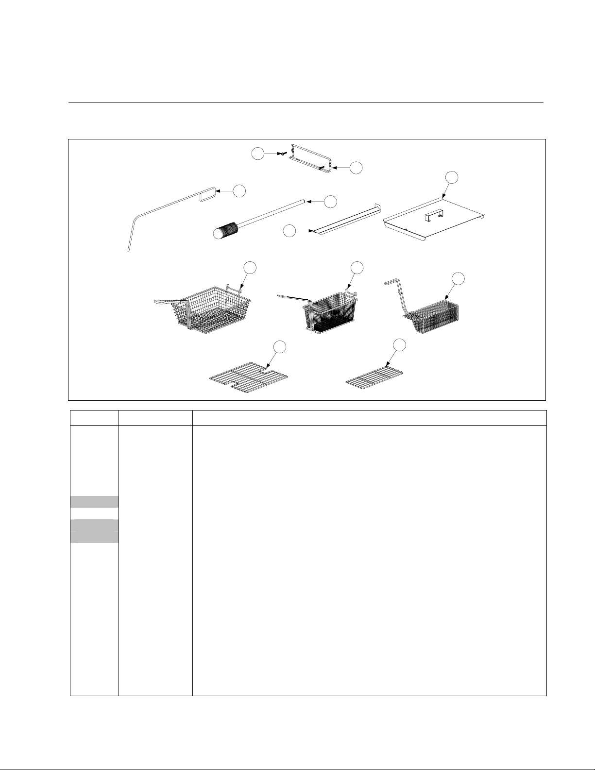
2.1 Accessories
RE SERIES E4 ELECTRIC FRYERS
CHAPTER 2: PARTS LIST
1
2
6
3
4
5
7
10
8
9
11
ITEM PART # COMPONENT
1 809-0171 Thumbscrew, ¼ -20 X 1⅜-inch
2 810-2793 Hanger, Wireform Basket (use 810-2794 for Fryer ½)
* 809-0921 Spacer, Basket Hanger
3 803-0197 Cleanout Rod, 27-inch
4 803-0209 Brush, Frypot
5 823-5772 Connecting Strip, Frypot (use 823-6000 for LH, use 823-5966 for RH Fryer ½)
823-5807 Connecting Strip, Frypot Deep Cabinet
6 806-3068 Cover, Full-Vat Frypot
806-3071 Cover, Dual-Vat Frypot
106-6349 Cover, Full-Vat Frypot Deep Cabinet
7 803-0099 Basket, Full-Vat
8 803-0271 Basket, Dual-Vat (Twin)
9 803-0122 Sediment Tray, Left Dual-Vat
* 803-0123 Sediment Tray, Right Dual-Vat
* 803-0113 Sediment Tray, Full-Vat (use 803-0365 for FV Deep Cabinet)
10 803-0132 Rack, Full-Vat Basket Support (use 803-0364 for FV Deep Cabinet)
11 803-0106 Rack, Dual-Vat Basket Support
* 824-1664 Spreader Pan
* 824-1720 Cover, Spreader Pan
* 805-1575 Heatlamp, Merco 120V 2 Bulb (use 806-5278SP for 120V Lamp Assembly)
* 805-1576 Heatlamp, Merco 240V 2 Bulb (use 806-5285SP for 240V Lamp Assembly)
* 803-0002 Powder, Filter (80 1-Cup Applications)
* 803-0170 Pack, 100-Sheet Filter Paper
* Not illustrated.
2-1
Page 2
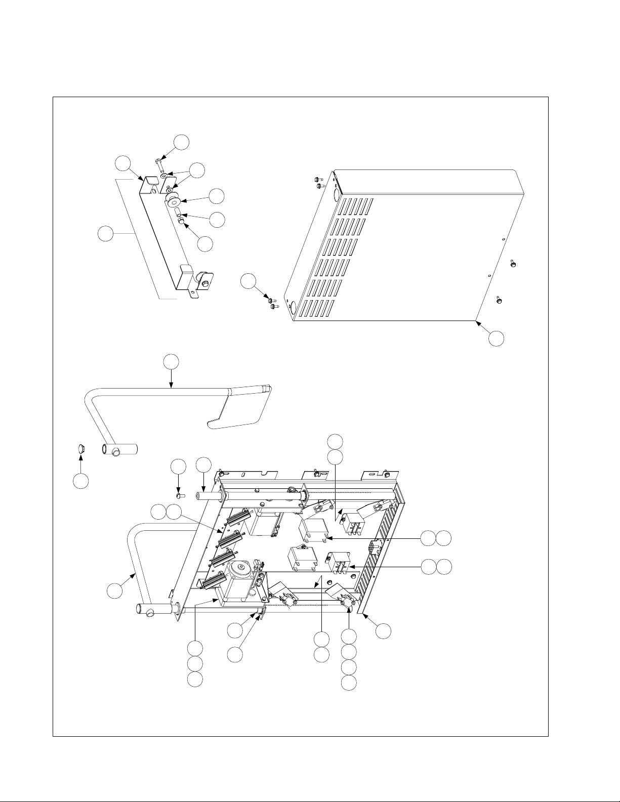
2.2 Basket Lift Assembly and Associated Parts
33
30
29
28
34
31
32
35
17
24
26
1
25
4 17
17
15
3
20
3
14
27
216
222110
181298
175
11
2-2
Page 3

2.2 Basket Lift Assembly and Associated Parts cont.
ITEM PART # COMPONENT
106-1805SP Basket Lift Assembly, 200-220VAC w/Relay (Items 1-23)
1 810-1012 Rod, Basket Lift
2 813-0035 Bushing, Bronze
3 807-2513 Capacitor, 12.5 μFarad 330VAC
4 901-8499 Chassis, Left Basket Lift
5 902-8499 Chassis, Right Basket Lift
6 807-0159 Connector, 12-Pin Female
7 900-5529 Gusset, Basket Lift Motor
8 812-0442 Insulation, Microswitch
9 807-2572 Microswitch
10 806-5964SP Motor Assembly, 208-240VAC Modular Basket Lift
11 200-2942 Mount, Modular Basket Lift
12 826-1366 Nut, 4-40 Hex Keps (Pkg. of 25)
13 809-0247 Nut, 8-32 Hex Keps
14 807-1683 Relay, 12VDC
15 106-2770SP Resistor Assembly, 208-220VAC Modular Basket Lift
16 809-0082 Ring, Bushing Retainer
17 826-1374 Screw, #10 X ½-inch Hex Washer Head (Pkg. of 25)
18 826-1359 Screw, 4-40 X ¾-inch Slotted Round Head (Pkg. of 25)
19 826-1361 Screw, 8-32 X 1-inch Slotted Truss Head (Pkg. of 25)
20 826-1371 Screw, #8 X ½-inch Drill Point Hex Head (Pkg. of 25)
21 809-0503 Screw, 8-32 X ½-inch Hex Head
22 809-0186 Washer, #8 Lock
23 WIR-0166SP Wire Bundle, 200-250VAC Basket Lift w/Relay
24 910-4776 Cover, Modular Basket Lift Rear S/S (Use 900-4776 for Mild Steel)
25 809-0127 Screw, ¼-20 X ½-inch Slotted Round Head
26 823-2704 Arm, Left Basket Lift
27 823-2705 Arm, Right Basket Lift
28 810-0179 Button, Plug
29 806-9110SP Roller Assembly, Basket Lift
30 910-8112 Bracket, Basket Lift Roller
31 810-0194 Roller, Basket Lift
32 810-0374 Spacer, Basket Lift Roller
33 809-0508 Bolt, ¼-20 X 1¼ -Inch
34 809-0190 Washer, ¼-inch Flat
35 809-0047 Nut, ¼-20 Cap
* 106-5957 Wiring Harness, RE Series Electric Basket Lift (Plugs into Item 6)
* Not illustrated.
2-3
Page 4
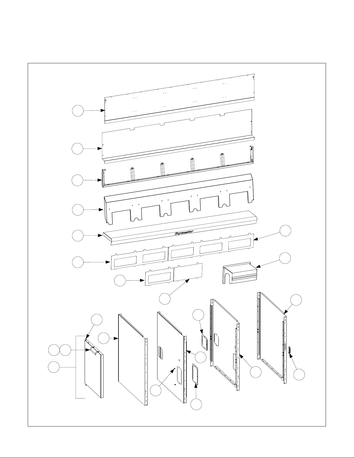
2.3 Cabinetry
2.3.1 Back Panels, Control Panel Frames, Doors, Sides, Tilt Housings, and Top Caps
1
2
3
14
13
15
4
5
20
16
6L
18
19
10
21
17
6R
8
9
7
12
11
2-4
Page 5

2.3.1 Back Panels, Control Panel Frames, Doors, Sides, Tilt Housings & Top Caps
cont.
ITEM PART # COMPONENT
1 Back Panel, Upper (Panel for five station fryer shown)
220-0421 Single Station Fryer CRS (Use 230-0422 for Stainless Steel)
220-1973 Fryer ½ Station Fryer CRS
220-0419 Two Station Fryer CRS (Use 230-0420 for Stainless Steel)
220-0423 Three Station Fryer CRS (Use 230-0424 fo r Stainless Steel)
220-0425 Four Station Fryer CRS (Use 230-0546 for Stainless Steel)
220-0611 Five Station Fryer CRS (Use 230-0612 for Stainless Steel)
2 Back Panel, Center (Panel for five station fryer shown)
220-0501 Single Station Fryer CRS (Use 230-0502 for Stainless Steel)
220-1977 Fryer ½ Station Fryer CRS
220-0487 Two Station Fryer CRS (Use 230-0490 for Stainless Steel)
220-0491 Three Station Fryer CRS (Use 230-0492 fo r Stainless Steel)
220-0499 Four Station Fryer CRS (Use 230-0500 for Stainless Steel)
220-0616 Five Station Fryer CRS (Use 230-0617 for Stainless Steel)
3 Frame, Control Panel (Frame for five station fryer shown)
106-5016 Single Station Fryer
106-6846 Fryer ½ Station Fryer
106-5221 Two Station Fryer
106-5018 Three Station Fryer
106-5019 Four Station Fryer
106-5020 Five Station Fryer
4 Tilt Housing (Housing for five station fryer shown)
823-5494 Single Station
823-5999 Fryer ½ Station LH ½ fryer (use 823-5965 for RH ½ fryer)
823-5497 Two Station
823-5489 Three Station
823-5575 Four Station (use 106-7516 for Cracker Barrel)
823-5581 Five Station
5 Top Cap (Top cap for five station fryer shown)
106-5195 Single Station (Also requires four 809-0078 10-32 Nutserts)
106-7060 Fryer ½ Station LH ½ fryer (use 106-6838 for RH ½ fryer) (Also requires four 809-
0078 10-32 Nutserts)
106-5196 Two Station (Also requires four 809-0078 10-32 Nutserts)
106-5197 Three Station (Also requires six 809-0078 10-32 Nutserts)
106-5198 Four Station (Also requires eight 809-0078 10-32 Nutserts)
106-5199 Five Station (Also requires ten 809-0078 10-32 Nutserts)
* Heat Shield
* 200-9614 Single Station
* 200-9610 Two Station (Two are used on Four Station) (One used on Five Station)
* 200-9611 Three Station (One used on Five Station)
6L 231-0323 Side, Standard Cabinet Left SS (use 221-0323SP for Enameled Steel)
231-1345 Side, Left Deep Cabinet SS
6R 232-0323 Side, Standard Cabinet Right SS (use 222-0323SP for Enameled Steel)
232-1345 Side, Right Deep Cabinet SS
7 810-1105 Magnet, Door
8 231-0352 Side, Filter Ready Cabinet Left SS (use 221-0352 for Cold Rolled Steel)
9 232-0352 Side, Filter Ready Cabinet Right SS (use 222-0352 for Cold Rolled Steel)
10 910-0889 Cover, 5-inch X 5-inch Access
11 910-0890 Cover, 5-inch X 7-inch Access
12 809-0359 Screw, #8 X ¼-inch Hex Washer Head
13 106-4397 Door, Left or Right (Left shown – move handle to opposite side for Right) - Standard
106-6899 Door, Left or Right – Fryer ½
14 809-0266 Screw, #10 X ½-inch Phillips Truss Head
15 210-9739 Handle, Eurolook Door (use 230-2088 for Fryer ½ handle)
* Not illustrated. continued on the following page...
2-5
Page 6

2.3.1 Back Panels, Control Panel Frames, Doors, Sides, Tilt Housings & Top Caps
cont.
ITEM PART # COMPONENT
16 106-4067 Pin Assembly, Door
* 810-0275 Spring, Door Pin
* 809-0970 Retaining Ring
17 823-5440 Cove, Element Tilt Housing (use 823-5726 for Fryer ½)
18 210-5046 Bezel, One-Controller (use 230-1953 for Fryer ½)
19 210-5623 Bezel, Blank
20 210-5819 Bezel, Two –Controller
21 210-6698 Bezel, Three-Controller
* Not illustrated.
2-6
Page 7
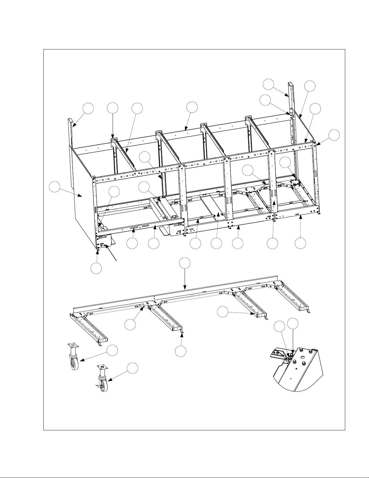
2.3.2 Cabinets, Bases, Braces, and Associated Parts
See Page 2-39 for rear
bridge support/oil return
manifold.
1
20
4
8
2
25
10
7
26
18
28
12
9
15
14
3
13
1117
6
16
5
See Page 2-34 for filter
19
rails and associated
29
24
23
30
21
19
The 5-Station cabinet illustrated is typical of most
RE Series Electric cabinets. All components used
in RE Series cabinets are identified, but not all
components are used in every configuration.
27
22
2-7
Page 8

2.3.2 Cabinets, Bases, Braces, and Associated Parts cont.
ITEM PART # COMPONENT
1 106-3828 Upright Assembly, Left
2 106-3829 Upright Assembly, Right
3 200-1651 Support, Cross Cabinet (use 220-1742 for Fryer ½)
4 200-1659 Divider, Cabinet (use 220-1348 for Deep Cabinet Divide r)
5 200-2293 Brace, Single Station Lower
6 200-3774 Brace, Double Station Lower
7 Brace, Front Horizontal
200-7036 Single-Station Fryer (use 220-0624 for Single-Station Lower Brace)
220-1740 Fryer ½ Station Fryer
200-7037 Two-Station Fryer
200-7038 Three-Station Fryer
200-7039 Four-Station Fryer
200-7040 Five-Station Fryer
8 Brace, Rear Horizontal
200-5356 Single-Station Fryer
220-1711 Fryer ½ Station Fryer
200-2284 Two-Station Fryer
200-2295 Three-Station Fryer
200-2725 Four-Station Fryer
200-3592 Five-Station Fryer
9 231-0323 Side, Cabinet LH S/S (use 221-0323 for CRS)(use 231-1345 for Deep Cabinet)
10 232-0323 Side, Cabinet RH S/S (use 222-0323 for CRS)(use 232-1345 for Deep Cabinet)
11 220-1100 Support, RE Bottom Contactor Box
12 220-1095 Support, RE Rear Contactor Box
13 220-1093 Brace, RE Front Contactor Box
* 220-1294 Brace, Contactor Box Single-Station Fryer Front
14 222-0610 Bracket, RH Contactor Box Mount (use 222-1845 for Fryer ½)
15 221-0610 Bracket, LH Contactor Box Mount (use 221-1845 for Fryer ½)
* 220-1446 Bracket, Contactor Box Mount SCF Deep Cabinet
* 200-6498 Bridge, Contactor Box Single-Station Fryer
16 200-4424 Post, Door
17 810-2346 Magnet, Door
18 200-4786 Support, Oil Return Manifold
19 210-6862 Hinge, Door
20 824-1393 Bracket, Rear Support (use 200-8253 for Fryer ½)
21 824-4557 Channel, Base Side
* 823-5782 Channel, Base Side SCF Deep Cabinet
* 221-0621 Channel, Base Left Side Single-Station Fryer (use 222-0621 for RH side)
22 809-0131 Bolt, ¼-20 X ¾-inch Hex Head (also used w/Item 27 to mount filter rails)
23 810-0326 Caster with Brake
24 810-1494 Caster without Brake
25 826-1376 Nut, 10-32 Keps Hex (Pkg. of 10)
26 826-1374 Screw, #10 X ½-inch Hex Washer Head (primary cabinet screw)(Pkg. of 25)
27 809-0417 Nut, ¼-20 Hex Flange
28 809-0429 Bolt, ¼-20 X 2-inch Hex Head
29 200-5417 Brace, Rear Channel Corner
30 Channel, Base Rear
823-5589 Single-Station Fryer Base (use 220-1737 for Fryer ½)
823-4558 Two-Station Fryer
823-4560 Three-Station Fryer
823-4561 Four-Station Fryer
823-4562 Five-Station Fryer
* 810-1234 Leg, Stainless Steel 8.5-inch Adjustable (mounts with Items 27 and 28)
* 810-3010 Leg, Single Fryer Single-Station Fryer
* Not illustrated.
2-8
Page 9
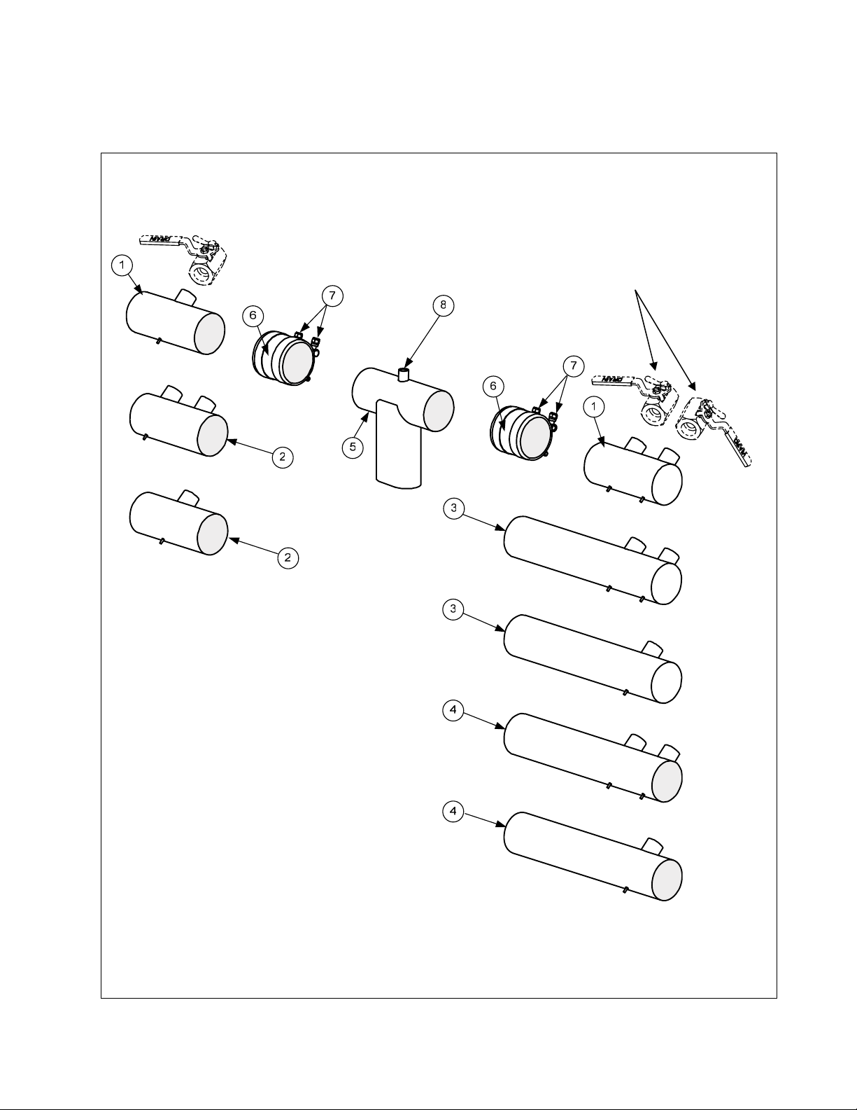
2.4 Drain System Components
2.4.1 Drain Tube Sections and Associated Parts
See next section for Drain Valves
2-9
Page 10

2.4.1 Euro-Look Drain Tube Sections and Associated Parts cont.
ITEM PART# COMPONENT
1 Drain Tube, Left/Right End Short
823-4625 Full-Vat
823-4624 Dual-Vat
823-5943 Fryer ½, RH ½ Fryer
823-6003 Fryer ½, LH ½ Fryer
2 Drain Tube, Left/Right Open Short
823-4643 Full-Vat
823-4642 Dual-Vat
3 Drain Tube, Right End Long
823-4639 Full-Vat
823-4638 Dual-Vat
4 Drain Tube, Left/Right Open Long
823-4641 Full-Vat
823-4640 Dual-Vat
5 823-4892 Drain Outlet Center Dump
823-5944 Fryer ½, RH ½ Fryer
823-6004 Fryer ½, LH ½ Fryer
6 816-0625 Sleeve
7 809-0969 Clamp
* 816-0630 Vinyl Cap
8 810-2492 Fitting, Quick-Connect Straight (receives Teflon vent tube)
* KIT6033 Kit, Round Drain Clamp (contains 2 of Item 7 and 1 of Item 6)
* 811-1071 Tube, Teflon Vent (sold by the foot)
* Not illustrated.
2-10
Page 11
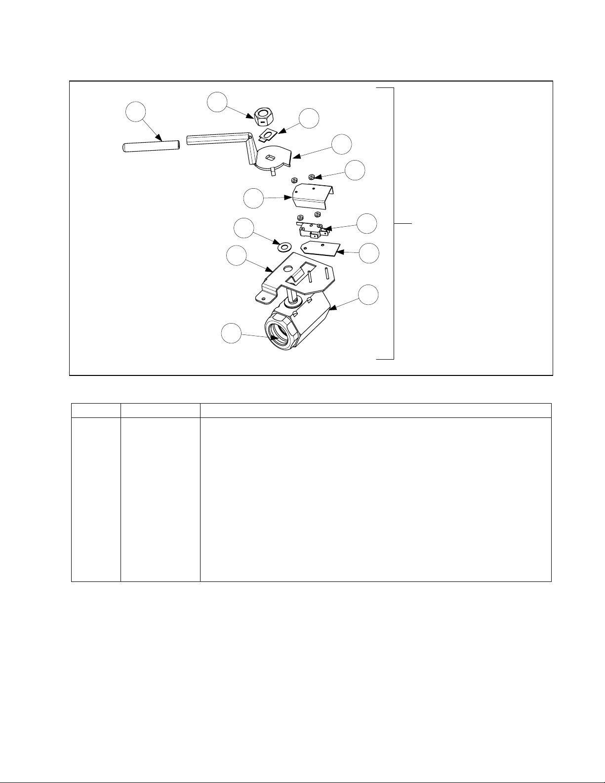
2.4.2 Drain Valves and Associated Parts (Units with Built-In Filtration)
4
2
3
5
6
1
Single Footprint Full-Vat
Drain Valve Assembly
106-6300
9
11
7
8
10
12
2.4.2 Drain Valves and Associated Parts (Units with Built-in Filtration) cont.
ITEM PART # COMPONENT
1 809-0540 Nut, ½-13 2-Way Hex Lock
2 900-2936 Retainer, Full-Vat Nut Drain Valve
3 824-1602 Handle, Full-Vat Drain Valve
4 816-0639 Cap, Red Handle
5 809-0237 Nut, 4-40 Keps Hex
6 901-2348 Cover, Dual Vat Drain Safety Switch
7 807-2103 Microswitch, CE Straight Lever
8 816-0220 Insulation, Drain Safety Switch
9 106-5391 Bracket Assembly, Full-Vat Drain Safety Switch Single FP Only
10 810-1018 Valve, 1.25-inch Full-Vat Drain
11 810-1165 Washer, Teflon Drain Valve
12 816-0135 O-Ring, Round Drain
2-11
Page 12
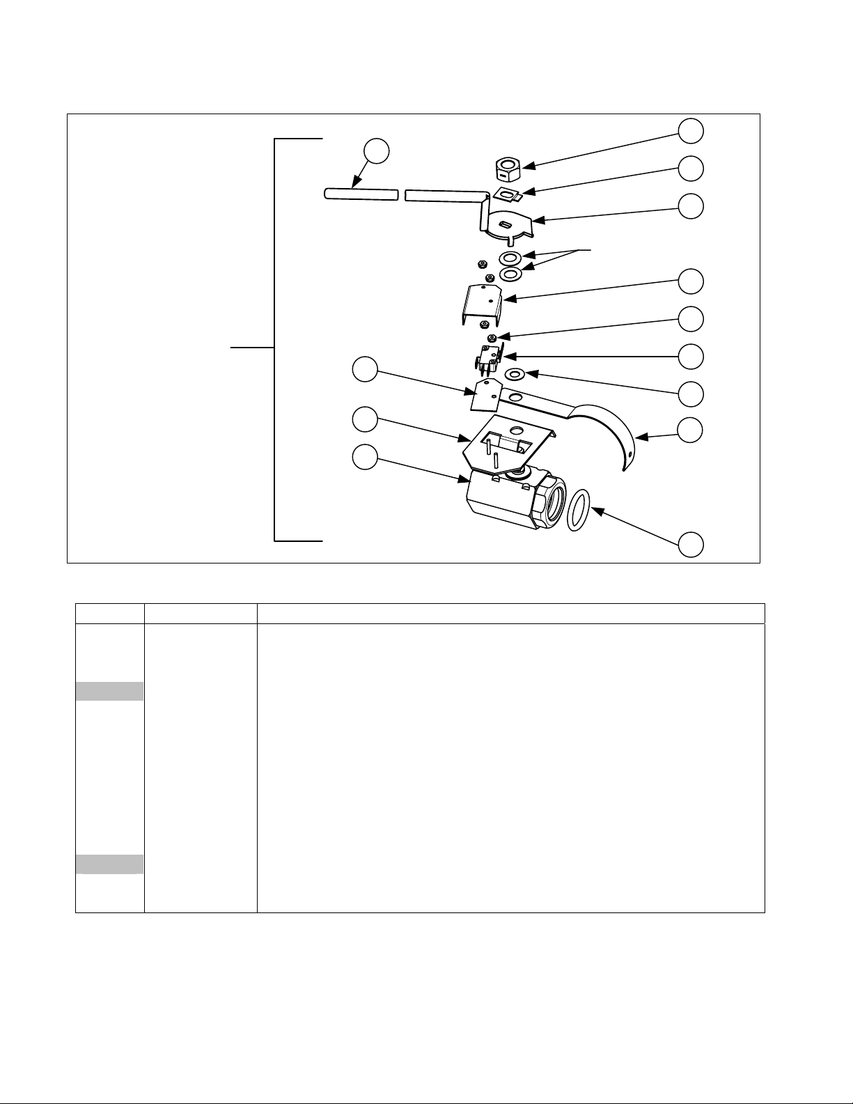
2.4.2 Drain Valves and Associated Parts (Units with Built-In Filtration) cont
4
Compression Washers
1
2
3
6
Full-Vat Drain Valve
Assembly 106-3760 /
Fryer ½ 106-7004
8
11
12
2.4.2 Drain Valves and Associated Parts (Units with Built-In Filtration) cont.
ITEM PA R T # COMPONENT
1 809-0540 Nut, ½-13 2-Way Hex Lock
2 900-2936 Retainer, Full-Vat Drain Valve Nut
3 824-1602 Handle, Full-Vat Drain Valve
824-1740 Handle, Fryer ½ Half Vat
4 816-0639 Cap, Red Handle
5 809-0237 Nut, 4-40 Keps Hex
6 901-2348 Cover, Dual Vat Drain Safety Switch
7 807-2103 Microswitch, CE Straight Lever
8 816-0220 Insulation, Drain Safety Switch
9 810-1165 Washer, Teflon Drain Valve
10 200-6496 Support, 3” Drain
11 806-8137 Bracket Assembly, Full-Vat Drain Safety Switch
106-7005 Bracket Assembly, Fryer ½
12 810-1018 Valve, 1.25-inch Full-Vat Drain
13 816-0135 Round Drain O-Ring
5
7
9
10
13
2-12
Page 13
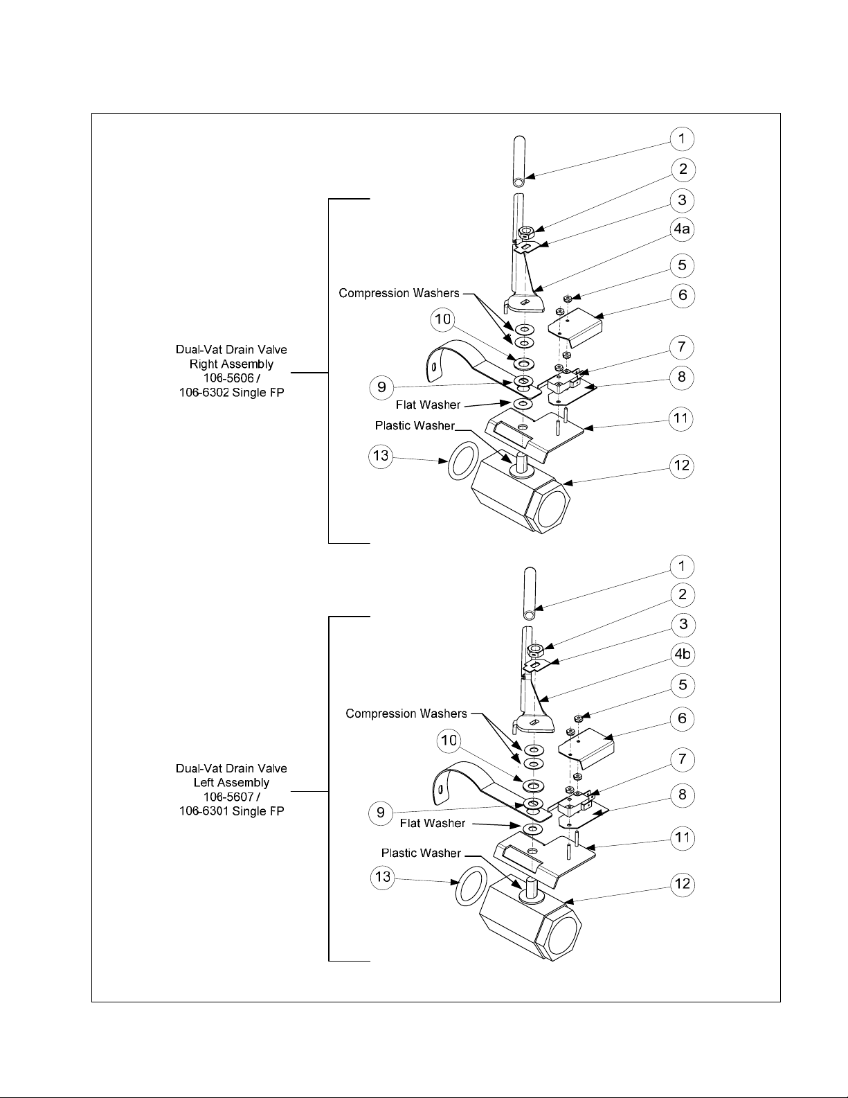
2.4.2 Drain Valves and Associated Parts (Units with Built-In Filtration) cont.
2-13
Page 14

2.4.2 Drain Valves and Assoc. Parts (Units with Built-In Filtration) cont.
ITEM PA R T # COMPONENT
1 816-0639 Cap, Drain Handle
2 809-0539 Nut, ⅜-16 2-Way Hex Lock
3 900-2934 Retainer, Dual-Vat Drain Valve Nut
4a 824-1636 Handle, Dual-Vat Right Drain Valve
4b 824-1637 Handle, Dual-Vat Left Drain Valve
5 809-0237 Nut, 4-40 Keps Hex
6 901-2348 Cover, Dual Vat Drain Safety Switch
7 807-2103 Microswitch, CE Straight Lever
8 816-0220 Insulation, Drain Safety Switch
9 810-1165 Washer, Teflon Drain Valve
10 809-0196 Washer, ⅜-inch Flat
11 106-2671 Bracket Assembly, Dual-Vat Drain Safety Switch
106-6304 Bracket Assembly, Dual-Vat Drain Safety Switch Single Footprint Only
12 810-1114 Valve, 1-inch Dual-Vat Drain
13 816-0135 Round Drain O-Ring
* 823-5592 Tube, Drain Single-Station Only with Filter
* Not illustrated.
2-14
Page 15

2.4.3 Drain Valves and Associated Parts (Units without Built-In Filtration)
1
4
5
ITEM PART # COMPONENT
1 810-1569 Valve, 1.25-inch Non-Filter Full-Vat Drain
2 806-7915SP Valve, 1-inch Non-Filter Dual-Vat Left Drain
3 806-7916SP Valve, 1-inch Non-Filter Dual-Vat Right Drain
4 812-1226 Drain Extension, 1.25-inch
5 812-1227 Drain Extension, 1-inch
2
3
2-15
Page 16

2.5 Electronics and Wiring Components
2.5.1 Component Boxes
2-16
Page 17

2.5.1 Component Boxes cont.
ITEM PART # COMPONENT
1 106-5592 Box Assembly, Component Standard
106-6747 Box Assembly, Component Fryer ½
2 200-3300 Bracket, Component Box Strain Relief
3 806-9495SP Terminal Block
4 807-0012 Relay, Filter 18 Amp ⅓ HP 24V
5 807-0670 Relay, Filter Mintex DPDT 24V
6 807-0037 Terminal, ¼-inch Push-on
7 807-0121 Bushing, Heyco Plastic AB-625-500
8 807-0922 Holder, Buss Fuse HPS
9 807-2278 Fuse, 20 Amp
10 810-2446 Plug, Button .50 Heyco Double “D”
11 807-4036 Switch
807-3575 Plug, Carling Switch Hole (used on some models without a switch)
12 807-1947 Plug, Button .875 Dome
13 807-1321 Holder, AGC Panel Mount ¼” Fuse (Some models use item 10 here.)
14 807-1597 Fuse, 3 AMP Slow-Blow
15 810-2445 Plug, Button .625 Heyco Double “D”
16 106-5750 Harness Assembly, RE FV Control
106-5751 Harness Assembly, RE DV Control
17 807-0855 Transformer, 100-120V/12V 20VA
18 807-0800 Transformer, 100-120V/24V 50VA Filter
19 807-0680 Transformer, 208-240V/24V 20VA Filter
20 807-2191 Transformer, 208-240V/12V 30VA
21 807-0979 Transformer, 208-240V/12V 43VA
22 807-2180 Transformer, 208-240V 50VA Filter
23 Interface Board (On SMT interface boards the relays are not replaceable.)
826-2260 Standard, Full- or Dual-Vat (SMT)
106-6693 EPRI, Full- or Dual-Vat
106-5290 Fast Computer, Full- or Dual-Vat
* 807-3932 Relay, Latch/Heat 12VDC SPDT 12A Sealed (On SMT interface
boards the relays are not replaceable.)
* 106-6501 Fallback Controller Assembly RE
24 220-0565 Guard, Finger Domestic and Non-CE
220-1061 Guard, Finger Non-Domestic and CE
25 200-6654 Brace, Component Box
26 230-0834 Guard, RE Box Switch
27 816-0217 Paper, Insulating Terminal Block
28 810-0045 Bushing, .875 Diameter 11/16”
29 806-7179SP Sound Device Std. (Use 810-3141 for SMT sound device with SMT
connector)
* 807-4330 Sound Device Adapter Harness (SMT)
30 809-0349 Spacer, 4mm X 6mm Aluminum
* 826-2249 RE Hood/Ansul Interlock Kit (includes terminal block, wires and connectors)
* Not illustrated.
2-17
Page 18

2.5.2 Contactor Boxes
2.5.2.1 Left and Right Over the Filter Pan Contactor Box Configurations
2-18
Page 19

2.5.2.1 Left and Right Over the Filter Pan Contactor Box Configurations cont.
NOTES: Left and right contactor box assemblies are mirror images of one another. With the exception of the
box itself, most components of a left-hand assembly are the same as those in the corresponding right-hand
assembly and vice versa. The configurations illustrated show most possible components, but a particular
configuration may not have all the components shown.
ITEM PART # COMPONENT
1 106-5488 Box Assembly, Left Contactor Standard (Over the Filter Pan)
106-7066 Box Assembly, Left Contactor Fryer ½ Half Fryer on Left
2 823-5736 Box Assembly, Left Contactor EPRI (Over the Filter Pan)
3 106-5489 Box Assembly, Right Contactor Standard (Over the Filter Pan)
106-6819 Box Assembly, Right Contactor Fryer ½ Half Fryer on Right
4 823-5748 Box Assembly, Right Contactor EPRI (Over the Filter Pan)
5 810-2554 Plug, Cord Cutout 1.125 Button
6 807-1947 Plug, .875 Diameter Dome
7 807-0064 Transformer, 480V/120V 150VA
8 807-0922 Holder, Bus Fuse
* 221-0482 Cover, Left Hand Standard Contactor Box
222-2072 Cover, Left Hand Fryer ½ Half fryer on Left
* 222-0482 Cover, Right Hand Standard Contactor Box
220-1912 Cover, Right Hand Fryer ½ Half fryer on Right
9 807-0070 Terminal, Ground Lug
10 807-1071 Contactor, 24V 30 Amp Mercury
11 807-0884 Contactor, 24V 50 Amp Mercury
12 807-2284 Contactor, 24V 50 Amp Mechanical (only in 14kW & 17kW units)
13 807-2283 Contactor, 24V 63 Amp Mechanical (only in 22kW units)
14 810-1202 Contactor, 24V 40 Amp Mechanical
15** 806-8674 Heatsink Assembly, DV Solid State Relay (See components below)
16** 806-8673 Heatsink Assembly, FV Solid State Relay (See components below)
Components of Items 15 and 16
17 826-1562 Kit Relay, Solid State 40 Amp 280V with Heatsink
18 807-2749 Heatsink, Solid State
19 807-0037 Terminal, ¼-inch Push-on
20 807-2278 Fuse, 20 Amp
21 106-6204 Filter Assembly, EPRI (used in CE WYE-configured EPRI units only)
22 807-0064 Transformer, 480V/120V 150VA
23 807-0922 Holder, Bus Fuse
* 221-0610 Bracket, Left Hand Contactor Box Mounting
* 222-0610 Bracket, Right Hand Contactor Box Mounting
* 807-0012 Relay, Tilt Switch 18 Amp 1/3 HP 24 V Coil
* Not illustrated. ** Full Vat has three relays 826-1562, Dual-Vat has six relays.
2-19
Page 20

2.5.2.2 Large Center Contactor Box Configurations (Non-Filter, Not over the Filter
and Single Units)
2-20
Page 21

2.5.2.2 Large Center Contactor Box Configurations (Non-Filter, Not Over the Filter
and Single Units) cont.
ITEM PART # COMPONENT
1 106-6081 Box Assembly, Contactor (Non-Filter or Not Over the Filter Pan)
1a 106-6255 Box, Assembly Contactor (Non-Filter or Not Over the Filter Pan)120/440/480V
2 106-6173 Box Assembly, Contactor EPRI (Non-Filter or Not Over the Filter Pan)
* 106-6244 Box Assembly, Contactor Single-Station Fryer Only
3 810-2554 Plug, Cord Cutout 1.125 Button
4 807-1947 Plug, .875 Diameter Dome
5 221-0482 Cover, Left Hand Contactor Box
6 222-0482 Cover, Right Hand Contactor Box
7 807-0070 Terminal, Ground Lug
8 807-1071 Contactor, 24V 30 Amp Mercury
9 807-0884 Contactor, 24V 50 Amp Mercury
10 807-2284 Contactor, 24V 50 Amp Mechanical (only in 14kW & 17kW units)
11 807-2283 Contactor, 24V 63 Amp Mechanical (only in 22kW units)
12 810-1202 Contactor, 600V 40 Amp 3-Pole
13** 806-8674 Heatsink Assembly, DV Solid State Relay (See components below)
14** 806-8673 Heatsink Assembly, FV Solid State Relay (See components below)
Components of Items 13 and 14
15 826-1562 Kit Relay, Solid State 40 Amp 280V with Heatsink
16 807-2749 Heatsink, Solid State
17 807-0037 Terminal, ¼-inch Push-on
18 807-2278 Fuse, 20 Amp
19 823-5729 Plate, Contactor Back Cordset
20 220-1087 Bracket, Box Connecting
21 220-1088 Cover, Contactor Box Front
22 220-1089 Cover, Contactor Box Top (Non-Filter or Not Over the Filter Pan)
* 220-1175 Cover, Contactor Box Top Full Vat Single-Station Fryer Only
* 220-1373 Cover, Contactor Box Top Dual Vat Single-Station Fryer Only
23 220-1152 Cover, Contactor Box Top EPRI (Non-Filter or Not Over the Filter Pan)
24 106-6204 Filter Assembly, EPRI (used in CE WYE-configured EPRI units only)
25 807-0064 Transformer, 480V/120V 150VA
26 807-0922 Holder, Bus Fuse
* 807-0012 Relay, Tilt Switch 18 Amp 1/3 HP 24 V Coil
*Not illustrated. ** Full Vat has three relays 826-1562, Dual-Vat has six relays.
2-21
Page 22

2.5.3 Fuse Boxes
Left 22kW and
Single Phase
Fuse Box Assembly
106-5505/106-6678
10
Right 22kW and
Single Phase
Fuse Box Assembly
106-5506/106-6679
11
9
8
6
7
12
5
1
3
2
ITEM PART # COMPONENT
1 200-2334 Door
2 810-0519 Hinge
3 221-0523 Cover, LH Fuse Box
4 222-0523 Cover, RH Fuse Box (Used on Single Station Fryers also)
5 809-0434 Screw, #10 x ⅜” Hex
6 823-5585 Box, LH Fuse
7 823-5557 Box, RH Fuse
823-5797 Box, Single Station Fryer Only
8 807-3970 Block, 3 Pole 600V 175A Terminal
9 807-0501 Fuse Block, Buss #2968 3-Pole
10 807-2240 Fuse, 60 AMP 300VAC
11 807-0070 Terminal, Ground Lug
12 807-0128 Bushing, Insulating Heyco
4
2-22
Page 23

2.5.4 Terminal Blocks
ITEM PART # COMPONENT
1 823-5631 Box, LH Rear Terminal Block
2 823-5632 Box, RH Rear Terminal Block
823-5797 Box, Single Station Fryer Only (see previous page for cover 222-0523)
3 220-0801 Cover, Rear Terminal Block Box
4 807-3970 Block, 3 Pole 600V 175A
5 807-0070 Terminal, Ground Lug
6 807-0128 Bushing, Insulating Heyco
2-23
Page 24

2.5.5 Heating Element Assemblies and Associated Parts
2.5.5.1 Element Assemblies and Hardware
NOTE: These elements apply only to the RE series fryers.
For the previous model elements see manual PN 819-5990.
2-24
Page 25

2.5.5.1 Heating Element Assemblies and Associated Parts cont.
ITEM PART # COMPONENT
1 Element Kits – includes ga skets, grommets, tie wraps, screws and nuts.
826-2198 200V 17.0 kW (also used for 220V 8.5 kW)
826-2201 200V 18.5 kW
826-2208 200V 11.0 kW
826-2192 208V 17.0 kW
826-2197 208V 18.5 kW
826-2210 208V 11.0 kW
826-2200 220V 17.0 kW (also used for 240V 8.5 kW)
826-2205 220V 11.0 kW
826-2193 230V 17.0 kW
826-2199 230V 18.5 kW
826-2206 230V 11.0 kW
826-2194 240V 17.0 kW
826-2207 240V 11.0 kW
826-2204 400V 8.5kW
826-2195 440V 17.0 kW
826-2202 440V 18.5 kW
826-2211 440V 11.0 kW
826-2196 480V 17.0 kW
826-2203 480V 18.5 kW
826-2209 480V 11.0 kW
2 826-2212 Probe, Temperature RE – includes tie wraps and grommet.
807-4324 Probe, Temperature Fast Ready
3 816-0681 Grommet, Probe
4 816-0480 Plug, .375-inch Dome
5 816-0688 Gasket, Element
6 809-1003 Screw, 10-32 X ⅜-inch Hex Head SS
* 809-0766 Nut, 10-32 Keps Hex Head SS
7 910-5022 Bracket, Temperature Probe 7.0 kW
230-0784 Bracket, Temperature Probe 8.5/11 kW
8 809-0518 Screw, 8-32 X ⅜-inch Slotted Hex Head
9 910-2042 Clamp, Element (Short)
10 230-0781 Clamp, Element (Long)
11 230-0780 Support, Full-Vat Element Rear
12 823-5621 Support, Full-Vat Element Front
13 809-0567 Tie-Wrap, Metal
14 810-1212 Pin, .125 X .5-inch Split
15 230-0791 Support, Dual-Vat Element Rear Dual Vat (used also in Front Dual Vat 22kw)
16 823-5624 Support, Dual-Vat Element Front Dual Vat 14kW
823-5627 Support, Dual-Vat Element Front Dual Vat 17kW
17 810-3030 Spring, Element Lift Left
810-3031 Spring, Element Lift Right
18 220-1190 Bracket, Lower Spring Single Foot Print
220-0464 Bracket, Lower Spring
220-1855 Bracket, Lower Spring Fryer ½
19 220-0733 Bracket, Lower Spring Mating
20 810-1233 Handle, Element Lift
* Not illustrated.
2-25
Page 26

2.5.5.2 Element Tube Assemblies
2-26
Page 27

2.5.5.2 Element Tube Assemblies cont.
ITEM PART # COMPONENT
1 106-5374 Tube Assembly RE Element, Full-Vat
106-6736 Tube Assembly RE Element Fryer ½ LH Half Fryer (use 106-6061 RH Half Fryer)
2 106-5457 Tube Assembly RE Element, Dual-Vat
3 106-5438 Bushing Assembly, Center Tube RE, Dual-Vat
809-0996 Bolt, Stand Hex 1 ½” x 3/8” – 16
809-0998 Washer, 3/8” SAE
809-0999 Nut, 3/8” 16, 2-Way Lock 18-8
810-2996 Bushing, Aluminum DV Tube
810-3013 Spacer, RE DV Bushing
4 106-5329 Bracket Assembly, LH Element Tube Support
5 106-5330 Bracket Assembly, RH Element Tube Support
6 220-0122 Plate, Element Tube Support Inner
7 220-0123 Plate, Element Tube Support Outer
8 106-6569 Bracket Assembly, LH Upper Spring
9 106-6570 Bracket Assembly, RH Upper Spring
10 826-1330 Screw, 10-32 X ⅜-inch Slotted Truss Head (Pkg. of 25)
11 809-0766 Nut, 10-32 Hex HD SS
12 106-6037 Tube, FV Element Mounting
810-3135 Tube, Fryer ½ LH Half Fryer (use 810-3036 RH Half Fryer)
13 810-2993 Bushing, Tube End Teflon
14 106-6038 Tube, DV Element Mounting, LH
15 106-6039 Tube, DV Element Mounting, RH
* 106-6587 Magnetic Position Sensor Assembly
* 106-6588 Magnetic Position Sensor Assembly with Bracket
* 810-3007 Magnet
* 230-0794 Bracket, Magnetic Position Sensor Wire
* Not illustrated.
2.5.6 Controllers
NOTE: See Page 2-33 for Interface Board to Controller Wiring Harness
ITEM PART # COMPONENT
1 Computer Magic III.5
106-4335SP Full-Vat (CE)
106-4336SP Dual-Vat (CE)
106-4373SP Full-Vat (Non-CE)
106-4374SP Dual-Vat (Non-CE)
106-4337SP Full-Vat (EPRI/Solid State)
106-4338SP Dual-Vat (EPRI/Solid State)
2-27
continued on the following page
Page 28

2.5.6 Controllers cont.
ITEM PART # COMPONENT
2 Digital Controller
106-4343 Full-Vat (CE)
106-4344 Dual-Vat (CE)
106-4339 Full-Vat (Non-CE)
106-4340 Dual-Vat (Non-CE)
3 Basket Lift Timer
106-4365 Full-Vat (CE)
106-4366 Dual-Vat (CE)
106-4363 Full-Vat (Non-CE)
106-4364 Dual-Vat (Non-CE)
4 Solid-State (Analog) Controller
106-4333 Full-Vat
106-4334 Dual-Vat
* 802-2021 Graphic Sheet of Symbols
2.5.7 Wiring
2.5.7.1 Contactor Box Wiring Assemblies – 12-Pin Dual-Vat C-1
1
2
3
4
5
1
2
6
7
8
9
10
11
12
1
2
3
4
5
6
7
8
9
10
11
12
GREEN/YELLOW 75C
BLUE 74C
ORANGE 73C
ORANGE 72C
ORANGE 76C
ORANGE 71C
ORANGE 72C
ORANGE 71C
YELLOW 184C
ITEM PART # COMPONENT
106-5980 Contactor Box Harness Assembly Dual Vat
1 Standard
2 EPRI
2-28
Page 29

2.5.7.2 Contactor Box Wiring Assemblies – 12-Pin Full-Vat C-1
1
2
3
4
5
1
2
6
7
8
9
10
11
12
1
2
3
4
5
6
7
8
9
10
11
12
GREEN/YELLOW 75C
BLUE 74C
ORANGE 76C
ORANGE 71C
ORANGE 71C
YELLOW 184C
1
2
3
4
5
3
6
7
8
9
10
11
12
GREEN/YELLOW 75C
BLUE 74C
ORANGE 76C
ORANGE 71C
ITEM PART # COMPONENT
106-6031 Contactor Box Harness Assembly Full Vat
1 Standard
2 EPRI
3 106-7042 Fryer and ½
2-29
Page 30

2.5.7.3 Contactor Box Wiring Assemblies – 6-Pin (Left Element)
1
2
1
2
3
4
5
6
1
2
3
4
5
6
BLUE
BLUE
BLUE
BLACK
BLACK
BLACK
BLUE
BLUE
BLUE
BLACK
BLACK
BLACK
ITEM PART # COMPONENT
1 106-6035 14/17 kW Standard (use 106-7001 for Fryer ½ Half Element)
106-6251 Single FP Element Harness 6-pin and 9-pin
2 106-6054 22 kW and Mechanical Contactor (MDI)
106-6252 Single 22kW and Mechanical Contactor (MDI) Element Harness 6 & 9-pin
2.5.7.4 Contactor Box Wiring Assemblies – 9-Pin (Right Element)
1
2
3
1
2
4
5
6
7
8
9
1
2
3
4
5
6
7
8
9
BLUE
BLUE
BLUE
BLACK
BLACK
BLACK
BLUE
BLUE
BLUE
BLACK
BLACK
BLACK
ITEM PART # COMPONENT
1 106-6036 14/17 kW Standard (use 106-7002 for Fryer ½ Half Element)
See above Single FP Element Harness 6 and 9-pin
2 106-6055 22 kW and Mechanical Contactor (MDI)
See above Single 22kW and Mechanical Contactor (MDI) Element Harness 6 & 9-pin
2-30
Page 31

2.5.7.5 Main Wiring Harnesses - Full and Dual Vat
C6
12-Pin Female Connector
807-0159 (Rear of Fryer)
12-Pin Male Connector
807-0160 (Contactor Box)
C1C6
C1
15-Pin Male Connector
807-0804 (Rear of Component Box)
USED ONLY ON
DUAL VAT
HARNESSES
J4
J4
FULL VAT HARNESS
807-4194
DUAL VAT HARNESS
807-4195
J4C1C6
2-31
Page 32

2.5.7.5 Main Wiring Harnesses – Fryer and ½
FRYER AND ½ HARNESS
807-4364
2-32
Page 33

2.5.7.6 Component Box, Filter Pump and Basket Lift Wiring Harnesses
1
2
4
3
ITEM PART # COMPONENT
1 106-5750 Full Vat Control Harness J4 to J2 (Standard)
106-6639 Full Vat Control Harness J4 to J2 (EPRI)
2 106-5751 Dual Vat Control Harness J4 to J1 and J2 (Standard)
106-6644 Dual Vat Control Harness J4 to J1 and J2 (EPRI)
3 106-5935 Filter Pump C2 to Component Box Wiring Harness
4 106-5957 Basket Lift Harness Assembly (Standard)
106-6640 Basket Lift Harness Assembly (EPRI)
2-33
Page 34

2.5.7.7 Component Box to Filter Pump Harness
2.5.7.8 Basket Lift Harness
2.5.7.9 Interface Board to Controller Wiring Harness – 15-Pin
2-34
Page 35

2.6 Filtration System Components
2-35
Page 36

2.6 Filtration System Components cont.
ITEM PART # COMPONENT
* 826-1979 Filter Pan Roller Kit (four each of Items 7 and 8)
* 826-1980 Service Filter Pan (Item 5 minus Item 2)
* 826-1981 Service Filter Pan Assembly (Service Filter Pan above plus Items 3 and 4)
* 826-1392 O-Ring (Pkg. of 5; used with Item 5)
* 813-0568 Plug, ⅛-inch Socket Head Pipe (component of Item 5; two required)
* 106-5911 Heater Strip Assembly, 100-120V 25W 18” 806-5933SP
* 106-2852SP Heater Strip Assembly, 208-250V 25W 18”
1 823-4787 Lid, Multi-Vat Fryers Filter Pan
106-6243 Lid, Single Station Fryer Only Full Vat Filter Pan
106-6310 Lid, Single-Station Fryer Only Dual Vat Filter Pan
106-6461 Lid, RE SCF Deep Cabinet Filter Pan
106-6735 Lid, Fryer ½ Filter Pan
2 810-2874 Crumb Tray, Multi-Vat Fryers(component of Item 5)
824-1707 Crumb Tray, Single Station Fryer Only
823-5812 Crumb Tray, RE SCF Deep Cabinet
824-1734 Crumb Tray, Fryer ½
3 810-2910 Hold-Down Ring for Paper 13.65 x 21.41 Multi-Vat Fryers
823-5774 Hold-Down Ring for Paper 8.98 x 19.39 Single Station Fryer Only
823-5811 Hold-Down Ring for Pad 15.75x 20.02 SCF Deep Cabinet
823-5934 Hold-Down Ring for Paper 8.98 x 21.04 Fryer ½
4 200-2124 SanaGrid Filter Screen Standard
220-1316 SanaGrid Filter Screen, Single Station Fryer Only
220-1461 SanaGrid Filter Screen, SCF Deep Cabinet
220-1795 SanaGrid Filter Screen, Fryer ½
5 106-2617SP Pan, One-Piece Filter Multi-Vat Fryers (includes Item 2)
823-5594 Pan, One-Piece Filter Single Station Fryer Only
823-5933 Pan, One-Piece Filter Fryer ½
823-5798
Pan, Filter RE SCF Deep Cabinet (use 810-2805 Caster Front, 2” and 810-2807
Caster Rear 2” rigid)
6 810-2012 Rail Set, Filter Pan Roller (includes one left and one right)
* 230-1381 Slide, Filter Pan SCF Deep Cabinet
826-1979 Roller Kit (includes 4 rollers, 4 nuts and 4 lock washers)
7 810-2198 Roller, Filter Pan and Rail
8 826-1372 Nut, ¼-20 Hex (Pkg. of 10)
* 809-0191 Washer, Lock 1/4 Spring ZP
9 823-4675 Bracket, Lid Support
10 Guide, Filter Pan Lid
200-3556 Left
200-6709 Right
11 809-0503 Screw, 8-32 X ½-inch Slotted Truss Head
12 809-0247 Nut, 8-32 Hex Keps
13 823-3879 Suction Tube, Multi-Vat Fryer
823-5591 Suction Tube, Single-Station Fryer
* Not illustrated.
Continued on next page…
2-36
Page 37

2.6 Filtration System Components cont.
ITEM PART # COMPONENT
14 200-4408 Rail, Left Pan Filter Multi-Vat Fryers
106-5981 Support Assembly, Left Single Station Fryer Only
220-1378 Support, Left Filter Pan SCF Deep Cabinet
220-2069 Support, Left Filter Pan Fryer ½
15 200-4409 Rail, Right Filter Pan Multi-Vat Fryers
106-5982 Support Assembly, Right Single Station Fryer Only
220-1379 Support, Right Filter Pan SCF Deep Cabinet
220-2070 Support, Right Filter Pan Filter ½
16 Motor and Gasket Kit
826-1785 100V 50/60 Hz
826-1712 115V 50/60 Hz
826-1756 208V 50/60 Hz
826-1270 220-240V 50/60 Hz
826-1755 250V 50/60 Hz
17 826-1264 Pump and Gasket Kit 4 GPM 2-piece
816-0093 Gasket, Pump/Motor
* 807-11973 Seal Kit, Pump Viking
810-2902 Pump, Viking 8 GPM SCF Deep Cabinet
18 807-2484 Valve, ¼-inch Solenoid
19 810-2493 Fitting, ¼-inch x 90° Quick-Connect
* 811-1071 Tubing, ¼-inch OD Teflon Vent (sold by the foot)
20 813-0342 Elbow, ½-inch 45° Street
21 813-0530 Tee, ½-inch X ¼-inch X ½-inch Reducing
22 813-0022 Nipple, ½-inch Close
23 813-0838 Nipple, ¼-inch Close
24 813-0304 Bushing, ½-inch to ¼-inch Flush
25 810-1668 Adapter, ⅝-inch to ½-inch NPT Male
26 810-1669 Adapter, ⅝-inch to ½-inch NPT Female
27 810-1680 Flexline, 6.5-inch Oil Return
28 810-1057 Flexline, 13-inch Oil Return
29 810-1043 Flexline, 9.5-inch Oil Return
30 Wiring Harness, Filter Pump
106-5910 115/120V Filter Harness
106-5906 208/230/240/250V Filter Harness
31 809-0401 Screw, 10-32 X ¾-inch Hex Trim Head (Pkg. of 5)
32 200-7112 Bridge, Filter Motor Multi-Vat Fryers
824-1705 Bridge Filter Motor Single Station Fryer Only
220-1346 Bridge, Filter Motor SCF Deep Cabinet
220-2080 Bridge, Filter Motor Fryer ½, Half Fryer LH side
220-1837 Bridge, Filter Motor Fryer ½, Half Fryer RH side
33 813-0003 Tee, ½-Inch
34 813-0298 Nipple, ½-inch 2.0-inch
35 813-0537 Nipple, ¼-inch 2.0-inch
36 813-0165 Elbow, ST ½-inch x ½-inch NPT 90° BM
* Not illustrated.
2-37
Page 38

2.7 Frypot Assemblies and Associated Parts
2-38
Page 39

2.7 Frypot Assemblies and Associated Parts cont.
ITEM PART # COMPONENT
1 Frypot Assembly (does not include Item 6)
2 823-5545SP Frypot, Full-Vat Filter with Insulation (for use on EPRI units)
3 823-5359SP Frypot, Full-Vat Filter w/o Insulation (for use on Standard units)
823-5996 Frypot, Half-Vat Filter w/o Insulation LH (for use on Fryer ½ LH units)
823-5723 Frypot, Half-Vat Filter w/o Insulation RH (for use on Fryer ½ RH units)
823-5783 Frypot, Full-Vat Filter w/o Insulation Deep Cabinet (for use on Standard Deep units)
4 823-5551SP Frypot, Dual-Vat Filter with Insulation (for use on EPRI units)
5 823-5482SP Frypot, Dual-Vat Filter w/o Insulation (for use on Standard units)
6 Thermostat Assembly, High-Limit
806-7543 Non-CE Full Vat 425°F (218°C) (17kW FV and 14kW FV)(Color-Coded
Black)
806-8035 Non-CE Dual Vat 435°F (224°C) (22kW, 17kW DV and 14 kW DV) (Color-
Coded Red)
806-8132 CE 415°F (213°C) (14kW and 17kW CE) (Color-Coded Yellow)
806-8536 CE 405°F (207°C) (22 kW FV and DV CE) (Color-Coded White)
7 812-0211 Insulation, Kaowool 17-inch X 10-inch X ½-inch (4 required per pot)
8 900-4100 Retainer, Side Insulation
9 900-4101 Retainer, Front Insulation
10 900-1345 Retainer, Rear Insulation
11 826-1376 Nut, 10-32 Keps Hex (Pkg. of 10)
NOTES: The frypots for EPRI-equipped units are insulated; those for non-EPRI (standard) units are
not. EPRI frypot assemblies 806-5545SP and 806-5551SP consist of Items 2 and 4 respectively, plus
insulation (Items 7-10). When replacing insulation or adding insulation to a bare frypot, the individual
pieces (sides, front, and back) are cut to fit from Item 7 when installed. Each frypot requires four uncut
pieces of insulation.
2-39
Page 40

2.8 Oil Return System Components
22
21
20
Rear-Flush Oil Return
Plumbing
Typical
19
Full-vat rear-flush plumbing is
shown on the left side of the oil
return manifold; dual-vat
plumbing is shown on the right
side. Plumbing for a two-fryer
battery is illustrated, but all
13b
13a
14
components except the oil return
11
manifold are the same
regardless of the number of
fryers in the battery.
13a
16
18
17
10
12
1
15
2
4
1
6
7
3
5
8
9
2-40
Page 41

2.8 Oil Return System Components cont.
ITEM
PART #
COMPONENT
1 106-5596 Handle Assembly, Full-Vat and Right Dual-Vat Rear Flush Complete
106-6410 Handle Assembly, Full-Vat Deep Cabinet Complete
2 106-5597 Handle Assembly, Left Dual-Vat Rear Flush Complete
3 807-2103 Microswitch, Straight Lever
4 106-5595 Bracket Assembly, Microswitch
5 200-5401 Bracket, Handle Retainer
6 816-0220 Insulation, Oil Return Microswitch
7 826-1366 Nut, 4-40 Keps Hex (Pkg. of 25)
8 810-2534 Rod, Full-Vat and Right Dual Vat Rear Flush
810-3081 Rod, Full-Vat Right Hand Deep Cabinet
810-2533 Rod, Left Dual Vat Rear Flush
9 816-0643 Grip, Oil Return Valve Handle
10 809-0601 Clip, Clevis
11 810-2532 Flexline, 7.0-inch Multi-Vat Units
810-1057 Flexline, 13.0-inch Single Footprint Only Full Vat and Dual Vat Left Side
810-1055 Flexline, 11.5-inch Single Footprint Only Dual Vat Right Side
12 810-1668 Adapter, ⅝-inch to ½-inch NPT Male
13a 813-0165 Elbow, ½-inch X 90° Street
* 813-0062 Elbow, ½-inch X 90° BM
* 813-0087 Nipple, ½-inch X 1.50-inch NPT
13b 813-0908 Adapter, ½-inch NPT M/T 90º (used only on cabinet side)
14 810-0278 Valve, ½-inch Ball
15 200-5438 Handle, Rear Flush Valve
16 900-2935 Retainer, Oil Return Valve Nut
17 813-0460 Nipple, ½-inch X 3.0-inch NPT
18 813-0907 Cap, 15/16-inch Valve Safety
Manifolds
* 810-3142 Manifold, Fryer ½ Station Fryer
19 810-3015 Manifold, Two-Station Fryer (use 810-2543 for non-filter units)
20 810-3016 Manifold, Three-Station Fryer (use 810-2544 for non-filter units)
21 810-3017 Manifold, Four-Station Fryer (use 810-2545 for non-filter units)
22 810-3018 Manifold, Five-Station Fryer (use 810-2546 for non-filter units)
* Not illustrated.
2-41
Page 42

2.9 Oil Disposal Plumbing
2-42
Page 43

2.9 Oil Disposal Plumbing cont.
ITEM PART # COMPONENT
106-5959 Plumbing, Front Oil Disposal
106-5933 Plumbing, Rear Oil Disposal
1 106-6033 Valve Assembly, Oil Disposal
2 220-0922 Rod, Oil Disposal
3 220-0963 Bracket, Oil Disposal Rod
4 807-2484 Valve, Solenoid ¼-inch NPT
5 809-0601 Clip, Clevis Right Rod End
6 810-0487 Coupling, Male
7 810-1043 Flexline, ½-inch ID x 9.50”
* 810-1055 Flexline, ½-inch ID x 11.50”
8 810-1668 Adaptor, Male ⅝-inch OD x ½-inch
9 810-2493 Fitting, 90° Quick Connect Tube
10 812-1803 Tubing, ¼-inch OD x 24.50” Teflon
11 813-0003 Tee, ½-inch x ½-inch x ½-inch BM
12 813-0022 Nipple, ½-inch x Close NPT BM
13 813-0062 Elbow, ½-inch 90° BM
14 813-0093 Nipple, ½-inch x 4.0” NPT BM
15 813-0165 Elbow, Street ½-inch x ½-inch NPT 90° BM
16 813-0173 Union, ½-inch NPT BM
17 813-0304 Bushing, ½-inch x ¼-inch BM Flush
18 813-0429 Nipple, ½-inch x 13.0” NPT BM
19 813-0571 Nipple, ¼-inch x 1½-inch BM
20 813-0807 Bushing, ¼-inch x ⅛-inch
21 816-0637 Cap, Vinyl Blue 5/16-inch x 3.0”
22 823-5685 Bracket, Assembly Quick Disconnect
823-5809 Bracket, Assembly Quick Disconnect SCF Deep Cabinet
23 813-0265 Nipple, ½-inch x 2.50” NPT BM
* 810-1669 Adapter, Female ⅞-inch O.D. x ½-inch
* 813-0253 Nipple, ½-inch x 10.00” NPT BM
* 813-0298 Nipple, ½-inch x 2.00” NPT BM
* 106-6407 Switch Assembly RE Wand
* Not illustrated.
2.10 Oil Disposal Wand
ITEM PART # COMPONENT
106-4395 Oil Disposal Wand Assembly
1 810-0490 Quick Disconnect ½-inch Female
2 810-1471 Hose, 24-inch
3 810-0603 Wand
2-43
Page 44

2.11 Wiring Connectors and Pin Connectors
1 2
6
11
7 9 10
3
8
12
4
13
ITEM PART # COMPONENT
1 807-1068 2-Pin Female
2 807-0158 6-Pin Female
3 807-0156 9-Pin Female
4 807-0159 12-Pin Female
5 807-0875 15-Pin Female
6 807-1067 2-Pin Male
7 807-0157 6-Pin Male
8 807-0155 9-Pin Male
9 807-0160 12-Pin Male
10 807-0804 15-Pin Male
11 826-1341 Terminal, Female Split Pin (pkg. of 25)
12 826-1342 Terminal, Male Split Pin (pkg. of 25)
13 807-2518 Plug, Mate-N-Lock (Dummy Pin)
5
2-44
Page 45

2.12 Fasteners
ITEM PART # COMPONENT
* 809-0429 Bolt, ¼-inch – 20 x 2.00-inch Hex Head ZP Tap
* 809-0514 Capscrew, 5/16-inch-18 NC Hex
* 809-0448 Clip, Tinnerman
* 826-1366 Nut, 4-40 Keps Hex (Pkg. of 25) (809-0237)
* 826-1358 Nut, 6-32 Keps Hex (Pkg. of 25) (809-0049)
* 809-0247 Nut, 8-32 Keps Hex
* 826-1376 Nut, 10-32 Keps Hex (Pkg. of 10) (809-0256)
* 809-0766 Nut, 10-32 Keps Hex SS
* 809-0581 Nut, ½ NPT Locking
* 809-0020 Nut Cap 10-24 NP
* 826-1372 Nut Grip ¼-inch 1/4-20 Hex NP (Pkg. of 10) (809-0059)
* 809-0417 Nut Flange ¼-inch 1/4-20 Serr
* 809-0535 Nut, "T" ¼-inch-20 x 7/16 SS
* 809-0540 Nut, Lock ½-inch-13 Hex 2-Way ZP
* 826-1359 Screw, 4-40 x ¾-inch Slotted Round Head (Pkg. of 25) (809-0354)
* 826-1365 Screw, 6-32 x ⅜-inch Slot Head (Pkg. of 25) (809-0095)
* 809-0357 Screw, 6 x ⅜-inch Phillips Head NP
* 809-0359 Screw, 8 x ¼-inch Hex Washer Head
* 809-0360 Screw, 8 x ⅜-inch Hex Washer Slot Head
* 826-1371 Screw, 8 x ½-inch Hex Head ZP (Pkg. of 25) (809-0361)
* 809-0364 Screw, 8 x ⅝-inch Hex Washer Head ZP
* 809-0518 Screw, 8-32 x ⅜-inch Hex Washer Slotted Head SS
* 809-0104 Screw, 8-32 x ½-inch Slotted Head ZP
* 826-1363 Screw, 8-32 x ½-inch NP (Pkg. of 25) (809-0103)
* 826-1360 Screw, 10-24 x 5/16-inch Round Slot Head ZP (Pkg. of 25) (809-0024)
* 826-1330 Screw, 10-32 x ⅜-inch Slot Head SS (809-0117)
* 809-1003 Screw, 10-32 x ⅜-inch Hex Trim Head SS
* 826-1375 Screw, 10-32 x ¾-inch Hex Trim Head SS (Pkg. of 5) (809-0401)
* 809-1000 Screw, 10-32 x 1¼-inch Hex Sck C/S
* 826-1374 Screw, 10 x ½-inch Hex Head (Pkg. of 25) (809-0412)
* 809-0266 Screw, 10 x ½-inch Phillips Head ZP
* 809-0434 Screw, 10 x ⅜-inch Hex Washer Head NP
* 809-0123 Screw, 10 x ¾-inch Slot Head
* 826-1389 Screw, 1/4-20 x ¾-inch Hex Head ZP (Pkg. of 10) (809-0131)
* 809-0582 Washer ½ NPT Locking
* 809-0184 Washer, #10 LK ZP
* 809-0190 Washer, .625 X .275 X 40 Flat SS
* 809-0191 Washer, Lock 1/4 Spring ZP
* 809-0193 Washer, Flat 1/4 Nylon
* 809-0194 Washer, Flat 5/16 ZP
2-45
 Loading...