

Frymaster FOOTPRINT 8195915, FOOTPRINT FPPH14, FOOTPRINT FPPH17, FOOTPRINT FPPH22 Installation & Operation Manual
Page 1
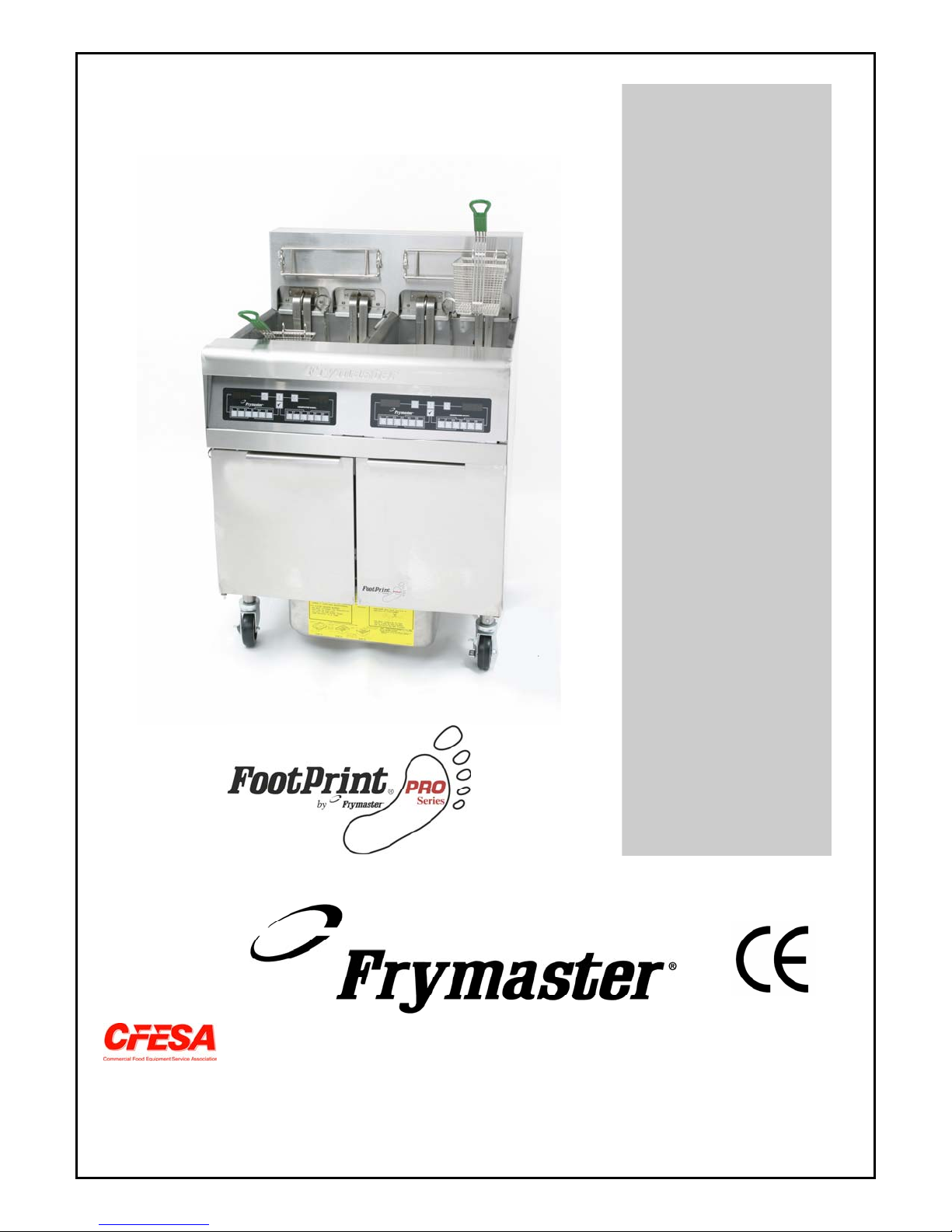
ELECTRIC FRYERS
Installation & Operation Manual
PRO SERIES
Frymaster, a member of the Commercial Food Equipment Service Association, recommends
using CFESA Certified Technicians.
24-Hour Service Hotline 1-800-551-8633
JANUARY 2005
*8195915*
Page 2
NOTICE
IF, DURING THE WARRANTY PERIOD, THE CUSTOMER USES A PART FOR THIS ENODIS
EQUIPMENT OTHER THAN AN UNMODIFIED NEW OR RECYCLED PART PURCHASED
DIRECTLY FROM FRYMASTER DEAN, OR ANY OF ITS AUTHORIZED SERVICE CENTERS,
AND/OR THE PART BEING USED IS MODIFIED FROM ITS ORIGINAL CONFIGURATION, THIS
WARRANTY WILL BE VOID. FURTHER, FRYMASTER DEAN AND ITS AFFILIATES WILL NOT BE
LIABLE FOR ANY CLAIMS, DAMAGES OR EXPENSES INCURRED BY THE CUST OMER WHICH
ARISE DIRECTLY OR INDIRECTLY, IN WHOLE OR IN PART, DUE TO THE INSTALLATION OF
ANY MODIFIED PART AND/OR PART RECEIVED FROM AN UNAUTHORIZED SERVICE CENTER.
NOTICE
This appliance is intended for professional use only and is to be operated by qualified
personnel only. A Frymaster Dean Factory Authorized Service Center (FASC) or other qualified
professional should perform installation, maintenance, and repairs. Installation, maintenance,
or repairs by unqualified personnel may void the manufacturer’s warranty. See Chapter 1 of
this manual for definitions of qualified personnel.
NOTICE
This equipment must be installed in accordance with the appropriate national and local codes of
the country and/or region in which the appliance is installed. See NATIONAL CODE
REQUIREMENTS in Chapter 2 of this manual for specifics.
NOTICE TO U.S. CUSTOMERS
This equipment is to be installed in compliance with the basic plumbing code of the Building
Officials and Code Administrators International, Inc. (BOCA) and the Food Service Sanitation
Manual of the U.S. Food and Drug Administration.
NOTICE
Drawings and photos used in this manual are intended to illustrate operational, cleaning and
technical procedures and may not conform to onsite management operational procedures.
NOTICE TO OWNERS OF UNITS EQUIPPED WITH COMPUTERS
U.S.
This device complies with Part 15 of the FCC rules. Operation is subject to the following two
conditions: 1) This device may not cause harmful interference, and 2) This device must accept
any interference received, including interference that may cause undesired operation. While
this device is a verified Class A device, it has been shown to meet the Class B limits.
This digital apparatus does not exceed the Class A or B limits for radio noise emissions as set
out by the ICES-003 standard of the Canadian Department of Communications.
Cet appareil numerique n’emet pas de bruits radioelectriques depassany les limites de classe A
et B prescrites dans la norme NMB-003 edictee par le Ministre des Communcations du Canada.
Improper installation, adjustment, maintenance or service, and unauthorized alterations or
modifications can cause property damage, injury, or death. Read the installation, operating,
and service instructions thoroughly before installing or servicing this equipment.
The front ledge of this appliance is not a step! Do not stand on the appliance. Serious injury
can result from slips or contact with the hot cooking oil/shortening.
CANADA
DANGER
DANGER
Page 3
DANGER
Do not store or use gasoline or other flammable liquids or vapors in the vicinity of this or any
other appliance.
DANGER
The crumb tray in fryers equipped with a filter system must be emptied into a fireproof container
at the end of frying operations each day. Some food particles can spontaneously combust if left
soaking in certain shortening material. Additional information can be obtained in the filtration
manual included with the system.
WARNING
Do not bang fry baskets or other utensils on the fryer’s joiner strip. The strip is present to seal
the joint between the fry vessels. Banging fry baskets on the strip to dislodge shortening will
distort the strip, adversely affecting its fit. It is designed for a tight fit and should only be
removed for cleaning.
NOTICE
All fryers shipped without factory supplied cords and plug assemblies must be hardwired using
flexible conduit to the terminal block located on the rear of the fryer. These fryers should be
wired to NEC specifications. Hardwired units must include installation of restraint devices.
DANGER
Single fryers equipped with legs must be stabilized by installing anchor straps. All fryers
equipped with casters must be stabilized by installing restraining chains
DANGER
Adequate means must be provided to limit the movement of this appliance without depending on
or transmitting stress to the electrical conduit. A restraint kit is provided with the fryer. If the
restraint kit is missing contact your local Frymaster Factory Authorized Service Center (FASC)
for part number 826-0900.
DANGER
This fryer may have two power cords and prior to movement, testing, maintenance and any
repair on your Frymaster fryer; disconnect BOTH electrical power cords from the electrical
power supply.
Page 4

Pro Series Electric Fryers
Installation and Operation Manual
TABLE OF CONTENTS
CHAPTER 1: Introduction
1.1 General Information ..........................................................................................................1-1
1.2 Safety Information............................................................................................................. 1-1
1.3 Computer Information....................................................................................................... 1-2
1.4 European Community (CE) Specific Information............................................................. 1-2
1.5 Shipping Damage Claim Procedure .................................................................................1-2
1.6 Service Information........................................................................................................... 1-3
CHAPTER 2: Installation Instructions
2.1 General Installation Requirements....................................................................................2-1
2.2 Power Requirements.......................................................................................................... 2-2
2.3 Positioning the Fryer Station............................................................................................. 2-3
CHAPTER 3: Operating Instructions
3.1 Setup and Shutdown Procedures.......................................................................................3-1
3.2 Controllers.........................................................................................................................3-2
CHAPTER 4: Filtration Instructions
4.1 Draining and Manual Filtering.......................................................................................... 4-1
4.2 Preparing the Built-In Filtration System for Use .............................................................. 4-2
4.3 Operation of the Filter....................................................................................................... 4-5
4.4 Disassembly and Reassembly of the Magnasol Filter....................................................... 4-8
4.5 Draining and Disposing of Waste Oil ............................................................................... 4-9
CHAPTER 5: Preventive Maintenance
5.1 Cleaning the Fryer.............................................................................................................5-1
Daily Checks and Service.................................................................................................. 5-1
Weekly Checks and Service.............................................................................................. 5-2
Boiling Out the Frypot ..................................................................................................... 5-2
Monthly Checks and Service............................................................................................. 5-3
5.2 Calibration of Solid State (Analog) Controller Knob........................................................5-3
5.3 Annual/Periodic System Inspection .................................................................................. 5-4
CHAPTER 6: Operator Troubleshooting
Introduction..................................................................................................................................6-1
6.2.1 Troubleshooting Controller and Heating Problems ..........................................................6-2
6.2.2 Troubleshooting Error Messages and Display Problems ..................................................6-4
6.2.3 Troubleshooting the Basket Lift........................................................................................ 6-7
6.2.4 Troubleshooting the Built-In Filtration System ................................................................ 6-7
i
Page 5
PRO SERIES ELECTRIC FRYERS
CHAPTER 1: INTROD UCTION
1.1 General
Read the instructions in this manual thoroughly before attempting to operate this equipment. This
manual covers all configurations of FPPH-14, FPPH-17, and FPPH-22 models. The fryers in this
model family have most parts in common, and when discussed as a group, will be referred to as “Pro
Series Electric” fryers.
Although similar in appearance to the Footprint III family of Common Electric fryers, the Pro Series
Electric fryers feature a significantly different built-in filtration system. Other features, including
the deep cold-zones and open frypots with tilt-up elements remain essentially unchanged. Control
options include multi-product cooking computers (standard) or optional digital and analog
controllers. Fryers in this series come in full- or split-pot arrangements, and can be purchased as
single units or grouped in batteries of up to six fryers.
1.2 Safety Information
Before attempting to operate your unit, read the instructions in this manual thoroughly.
Throughout this manual, you will find notations enclosed in double-bordered boxes similar to the
one below.
DANGER
Hot cooking oil causes severe burns. Never attempt to move a fryer containing hot
cooking oil/shortening or to transfer hot cooking oil/shortening from one container
to another.
CAUTION boxes contain information about actions or conditions that may cause or result in a
malfunction of your system.
WARNING boxes contain information about actions or conditions that may cause or result in
damage to your system, and which may cause your system to malfunction.
DANGER boxes contain information about actions or conditions that may cause or result in
injury to personnel, and which may cause damage to your system and/or cause your system to
malfunction.
Fryers in this series are equipped with the following automatic safety features:
1. Two high-temperature detection features shut off power to the elements should the temper ature
controls fail.
2. A safety switch built into the drain valve prevents the elements from heating with the drain valve
even partially open.
1-1
Page 6
1.3 Computer Information
This equipment has been tested and found to comply with the limits for a Class A digital device,
pursuant to Part 15 of the FCC rules. While this device is a verified Class A device, it has been
shown to meet the Class B limits. These limits are designed to provide reasonable protection against
harmful interference when the equipment is operated in a commercial environment. This equipment
generates, uses and can radiate radio fr equency energy and, if not installed and used in accordance
with the instruction manual, may cause harmful interference to radio communications. Operation of
the equipment in a residential area is likely to cause harmful interference in which case the user will
be required to correct the interference at his own expense.
The user is cautioned that any changes or modifications not expressly approved by the party
responsible for compliance could void the user's authority to operate the equipment.
If necessary, the user should consult the dealer or an experienced radio and television technician for
additional suggestions.
The user may find the following booklet prepared by the Federal Communications Commission
helpful: "How to Identify and Resolve Radio-TV Interference Problems". This booklet is available
from the U.S. Government Printing Office, Washington, DC 20402, Stock No. 004-000-00345-4.
1.4 European Community (CE) Specific Information
The European Community (CE) has established certain specific standards regarding equipment of
this type. Whenever a difference exists between CE and non-CE standards, the information or
instructions concerned are identified by means of shadowed boxes similar to the one below.
CE Standard
Example of box used to distinguish CE and
Non-CE specific information.
1.5 Shipping Damage Claim Procedure
What to do if your equipment arrives damaged:
Please note that this equipment was carefully inspected and packed by skilled personnel before
leaving the factory. The freight company assumes full responsibility for safe delivery upon
acceptance of the equipment.
1. File Claim for Damages Immediately—Regardless of extent of damage.
2. Visible Loss or Damage—Be sure this is noted on the freight bill or express receipt and is signed
by the person making the delivery.
3. Concealed Loss or Damage—If damage is unnoticed until equipment is unpacked, notify the
freight company or carrier immediately and file a concealed dama ge claim. This should be done
within 15 days of date of delivery. Be sure to retain container for inspection.
1-2
Page 7

1.6 Service Information
For non-routine maintenance or repairs, or for service information, contact your local Frymaster
Authorized Service Center (FASC). Service information may also be obtained by calling the
Frymaster Technical Services Department (1-800-24FRYER). The following information will be
needed in order to assist you efficiently:
Model Number _________________________
Serial Number _________________________
Voltage_______________________________
Nature of the Problem ___________________
_____________________________________
_____________________________________
RETAIN AND STORE THIS MANUAL IN A SAFE PLACE FOR FUTURE USE.
1-3
Page 8
PRO SERIES ELECTRIC FRYERS
CHAPTER 2: INSTALLATION INSTRUCTIONS
2.1 General
Proper installation is essential for the safe, efficient, trouble-free operation of this appliance.
Any unauthorized alteration of this equipment will void the Frymaster warranty.
NOTICE
If this equipment is wired directly into the electrical power supply, a means for
disconnection from the supply having a contact separation of at least 3-mm in all
poles must be incorporated in the fixed wiring.
NOTICE
This equipment must be positioned so that the plug is accessible unless other
means for disconnection from the power supply (e.g., a circuit breaker) is provided.
NOTICE
If this appliance is permanently connected to fixed wiring, it must be connected by
means of copper wires having a temperature rating of not less than 167°F (75°C).
NOTICE
If the electrical power supply cord is damaged, it must be replaced by a Frymaster
Dean Factory Authorized Service Center technician or a similarly qualified person in
order to avoid a hazard.
DANGER
This appliance must be connected to a power supply having the same voltage and
phase as specified on the rating plate located on the inside of the appliance door.
DANGER
All wiring connections for this appliance must be made in accordance with the wiring
diagram(s) furnished with the appliance. Refer to the wiring diagram(s) affixed to the
inside of the appliance door when ins talling o r serv icing this eq uipment.
DANGER
Frymaster appliances equipped with legs are for stationary installations. Appliances
fitted with legs must be lifted during movement to avoid damage to the appliance
and bodily injury. For movable installations, optional equipment casters must be
used. Questions? Call 1-800-551-8633.
2-1
Page 9
DANGER
Do not attach an apron drainboard to a single fryer. The fryer may become unstable,
tip over, and cause injury. The appliance area must be kept free and clear of
combustible material at all times.
All installation and service on FRYMASTER equipment must be performed by qualified, certified,
licensed, and/or authorized installation or service personnel.
Service may be obtained by contacting your local Factory Authorized Service Center.
In the event of a power failure, the fryer(s) will automatically shut down. If this occurs, turn the
power switch OFF. Do not attempt to start the fryer(s) until power is restored.
This appliance must be kept free and clear of combustible material, except that it may be installed on
combustible floors.
A clearance of 6 inches (15cm) must be provided at both sides and back adjacent to combustible
construction. A minimum of 24 inches (61cm) should be provided at the front of the equipment for
servicing and proper operation.
In Australia
To be installed in accordance with AS 5601 / AG 601, local authority, gas, electricity, and any other
relevant statutory regulations.
Do not block the area around the base or under the fryers.
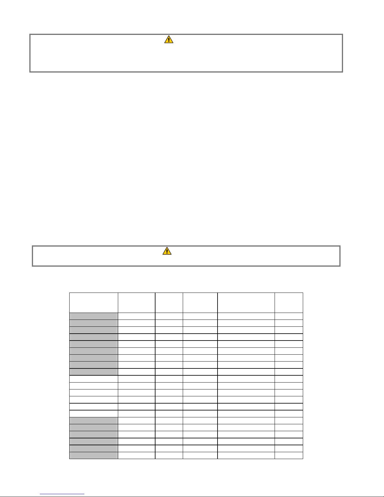
2.2 Power Requirements
MODEL VOLTAGE PHASE
FPPH14 208 Single 3 3 (5.83) 68
FPPH14 208 3 3 6 (4.11) 39
FPPH14 240 Single 3 4 (5.19) 59
FPPH14 240 3 3 6 (4.11) 34
FPPH14 480 Single 3 8 (3.26) 30
FPPH14 480 3 3 8 (2.59) 17
FPPH14 220/380 3 4 6 (4.11) 21
FPPH14 240/415 3 4 6 (4.11) 20
FPPH14 230/400 3 4 6 (4.11) 21
FPPH17 208 3 3 6 (4.11) 48
FPPH17 240 3 3 6 (4.11) 41
FPPH17 480 3 3 6 (4.11) 21
FPPH17 220/380 3 4 6 (4.11) 26
FPPH17 240/415 3 4 6 (4.11) 24
FPPH17 230/400 3 4 6 (4.11) 25
FPPH22 208 3 3 4 (5.19) 61
FPPH22 240 3 3 4 (5.19) 53
FPPH22 480 3 3 6 (4.11) 27
FPPH22 220/380 3 4 6 (4.11) 34
FPPH22 240/415 3 4 6 (4.11) 31
FPPH22 230/400 3 4 6 (4.11) 32
WARNING
WIRE
SERVICE
MINIMUM WIRE
SIZE
AWG (mm)
AMPS
(per leg)
2-2
Page 10
NOTICE
If this appliance is permanently connected to fixed wiring, it must be connected by
means of copper wires having a temperature rating of not less than 167°F (75°C).
DANGER
This appliance must be connected to a power supply having the same voltage and
phase as specified on the rating plate located on the inside of the appliance door.
DANGER
All wiring connections for this appliance must be made in accordance with the
wiring diagram(s) furnished with the appliance. Refer to the wiring diagram(s)
affixed to the inside of the appliance door when installing or servicing this
equipment.
2.3 After Fryers Are Positioned At the Frying Station
DANGER
No structural material on the fryer should be altered or removed to accommodate
placement of the fryer under a hood. Questions? Call the Frymaster Dean Service
Hotline at 1-800-551-8633.
DANGER
Adequate means must be provided to limit the movement of this appliance without depending
on or transmitting stress to the electrical conduit. A restraint kit is provided with the fryer. If
the restraint kit is missing contact your local Frymaster Factory Authorized Service Center
(FASC) for part number 826-0900.
1. Once the fryer has been positioned at the frying station, use a carpenter’s level placed across the
top of the frypot to verify that the unit is level, both side-to-side and front-to-back.
To level fryers equipped with legs, the bottom of the legs can be screwed out up to one inch for
leveling. Legs should also be adjusted so that the fryer(s) are at the proper height in the frying station.
For fryers equipped with casters, there are no built-in leveling devices. The floor where the
fryers are installed must be level.
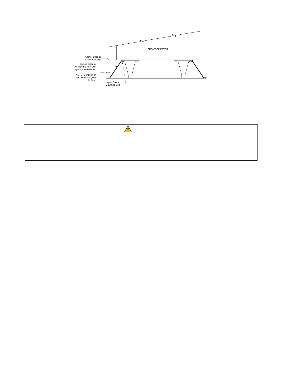
When the fryer is leveled in its final position, install the restraints provided with the unit to limit
its movement so that it does not depend on or transmit stress to the electrical conduit or
connection. Install the restraints in accordance with the provided instructions (see illustration on
the following page). If the restraints are disconnected for service or other reasons, they must be
reconnected before the fryer is used.
2-3
Page 11
NOTE: If you need to relocate a fryer installed with legs, remove all weight from each leg
before moving. If a leg becomes damaged, contact your service agent for immediate repair or
replacement.
DANGER
Hot shortening can cause severe burns. Avoid contact. Under all circumstances, oil
must be removed from the fryer before attempting to move it to avoid oil spills, falls
and severe burns. This fryer may tip and cause personal injury if not secured in a
stationary position.
1. Close fryer drain-valve(s) and fill frypot with water to the bottom oil level line.
3. Boil out frypot(s) in accordance with the instructions in Section 5.1.3 of this manual.
4. Drain, clean, and fill frypot(s) with cooking oil. (See Equipment Setup and Shutdown
Procedures in Chapter 3.)
2-4
Page 12
PRO SERIES ELECTRIC FRYERS
CHAPTER 3: OPERATING INSTRUCTIONS
3.1 Equipment Setup and Shutdown Procedures
Setup
DANGER
Never operate the appliance with an empty frypot. The frypot must be filled with
water or cooking oil/shortening before energizing the elements. Failure to do so will
result in irreparable damage to the elements and may cause a fire.
DANGER
Remove all drops of water from the frypot before filling with cooking oil or
shortening. Failure to do so will cause spattering of hot liquid when the oil or
shortening is heated to cooking temperature.
1. Fill the frypot with cooking oil to the bottom OIL LEVEL line located on the rear of the frypot.
This will allow for oil expansion as heat is applied. Do not fill cold oil any higher than the
bottom line; overflow may occur as heat expands the oil.
NOTE: If solid shortening is used, first raise the elements, then pack the shortening into the
bottom of the frypot. Lower the elements, and then pack the shortening around and over the
elements. It may be necessary to add shortening to bring the lev el up to th e proper mark after the
packed shortening has melted.
DANGER
Never set a complete block of solid shortening on top of the heating elements.
When using solid shortening, always pre-melt the shortening before adding it to the
frypot. If the shortening is not pre-melted, it must be packed down into the bottom of
the frypot and between the elements, and the fryer must be started in the melt-cycle
mode.
Never cancel the melt-cycle mode when using solid shortening. Doing so will result
in damage to the elements and increase the potential for a flash fire.
2. Ensure that the power cord(s) is/are plugged into the appropriate recept acle(s). Verify that the
face of the plug is flush with the outlet plate, with no portion of the prongs visible.
3. Ensure that the oil/shortening level is at the top OIL LEVEL line when the oil/shortening is at its
cooking temperature. It may be necessary to add oil/shortening to bring the level up to the
proper mark, after it has reached cooking temperature.
3–1
Page 13

Shutdown
1. Turn the fryer off.
2. Filter the cooking oil/shortening and clean the fryers (See Chapters 4 and 5).
3. Place the frypot covers on the frypots.
3.2 Controllers
This fryer may be equipped with any of the following controllers:
Computer Magic III (CM III)
Basket Lift Timer
Digital Controller
Solid State (Analog) Controller
SOLID STATE
3–2
Page 14

CAUTION
If this is the first time the fryer is being used after installation, refer to the frypot Boil-Out Procedure
on Page 5-2.
Refer to the separat e Frymaster Fryer Controllers User’s Manual furnished with your fryer for the
specific controller operating instructions.
Refer to Chapter 4 of this manual for operating instructions for the built-in filtration system.
3–3
Page 15

PRO SERIES ELECTRIC FRYERS
CHAPTER 4: FILTRATION INSTRUCTIONS
WARNING
The on-site supervisor is responsible for ensuring that operators are made aware of
the inherent hazards of operating a hot oil filtering system, particularly the aspects
of oil filtration, draining and cleaning procedures.
4.1 Draining and Manual Filtering
DANGER
Draining and filtering of cooking oil or shortening must be accomplished with care to
avoid the possibility of a serious burn caused by careless handling. The oil to be
filtered is at or near 350°F (177°C). Ensure all hoses are connected properly and
drain handles are in their proper position before operating any switches or valves.
Wear all appropriate safety equipment when draining and filtering cooking oil or
shortening.
DANGER
Allow oil/shortening to cool to 100°F (38°C) before draining into an appropriate
container for disposal.
DANGER
Do not drain more than one frypot at a time into the built-in filtration unit to avoid
overflow and spillage of hot oil/shortening.
DANGER
When draining oil/shortening into a disposal unit or portable filter unit, do not fill
above the maximum fill line located on the container.
If your fryer is not equipped with a built-in filtration system, the cooking oil or shortening must be
drained into another suitable container. (For safe, convenient draining and disposal of used cooking
oil or shortening, Frymaster recommends using the Frymaster Shortening Disposal Unit (SDU). The
SDU is available through your local distributor.)
1. Turn the fryer power switch to the OFF position. Screw the drainpipe (provided with your fryer)
into the drain valve. Make sure the drainpipe is firmly screwed into the drain valve and that the
opening is pointing down.
2. Position a metal container with a sealable cover under the drainpipe. The metal container must
be able to withstand the heat of the cooking oil/shortening and hold hot liquids. If you intend to
reuse the oil or shortening, Frymaster recommends that a Frymaster
cone be used when a filter machine is not available. If you are using a Frymaster filter cone
holder, be sure that the cone holder rests securely on the metal container.
filter cone holder and filter
4-1
Page 16

3. Open the drain valve slowly to avoid splattering. If the drain valve becomes clogged with food
particles, use the Fryer’s Friend (poker-like tool) to clear the blockage.
DANGER
NEVER attempt to clear a clogged drain valve from the front of the valve! Hot oil or
shortening will rush out creating the potential for severe burns.
DO NOT hammer on the drain valve with the cleanout rod or other objects. Damage
to the ball inside will result in leaks and will void the Frymaster warranty.
4. After draining the oil/shortening, clean all food particles and residual oil/shortening from the
frypot. BE CAREFUL, this material may still cause severe burns if it comes in contact with bare
skin.
5. Close the drain valve securely and fill the frypot with clean, filtered or fresh cooking oil or solid
shortening to the bottom OIL-LEVEL line.
DANGER
When using solid shortening, pack the shortening down into the bottom of the
frypot. DO NOT operate the fryer with a solid block of shortening sitting in the upper
portion of the frypot. This will cause damage to the frypot and may cause a flash
fire.
4.2 Preparing the Built-In Filtration System for Use
The FootPrint Pro filtration system allows the cooking oil or shortening in one frypot to be safely
and efficiently filtered while the other frypots in a battery remain in operation. The FootPrint Pro
filtration system is available in three different configurations:
• Filter Paper – includes crumb tray, large hold-down ring, and metal filter screen.
• Filter Pad – includes crumb tray, small hold-down ring, and metal filter screen.
• Magnasol Filter – includes crumb tray and Magnasol filter assembly.
Section 4.2.1 covers preparation of the Filter Paper and Filter Pad configurations for use. Refer to
Section 4.2.2 for instructions on preparing the Magnasol Filter configuration for use. Operation of
all three configurations is the same and is covered in section 4.3. Disassembly and reassembl y of the
Magnasol filter is covered in section 4.4.
4-2
Page 17

4.2.1 Preparation for Use with Filter Paper or Filter Pad
1. Pull the filter pan out from the cabinet
and remove the crumb tray, hold-down
ring, filter paper and filter screen. (See
Figure 1) Clean all components with a
Filter Paper
Screen
solution of detergent and hot water, then
dry thoroughly.
Crumb Tray
The filter pan is equipped with rollers in
rails, much like a kitchen drawer. The
pan may be removed for cleaning or to
gain access to interior components by
lifting the front of the pan to disengage
the front rollers, then pulling it forward
until the rear rollers clear the rails. The
pan cover must not be removed except
for cleaning, interior access, or to allow
a shortening disposal unit (SDU) to be
positioned under the drain.
Hold-Down Ring
Figure 1
2. Inspect the filter pan connection fitting
to ensure that both O-rings are in good
condition. (See Figure 2)
3. Then in reverse order, place the metal
filter screen in the center of the bottom
of the pan, then lay a sheet of filter paper
on top of the screen, overlapping on all
sides. (See Figure 1) If using a filter
pad, ensure the rough side of the pad is
up and lay the pad over the screen,
making sure that the pad is in between
the embossed ridges of the filter pan.
4. Position the hold-down ring over the
filter paper and lower the ring into the
pan, allowing the paper to rest on the
sides of the filter pan. (See Figure 3)
Inspect the filter
connection fitting
O-rings.
Figure 2
Figure 3
4-3
Page 18

5. When the hold-down ring is in position,
if using filter paper, sprinkle one cup of
filter powder evenly over the paper. (See
Figure 4)
If using a filter pad, position the hold
down ring on top of the pad. DO NOT
use filter powder with the pad.
Figure 4
6. Replace the crumb tray in the filter pan, then push the filter pan back into the fryer, positioning it
all the way to the back of the cabinet.
4.2.2 Preparation for Use with the Magnasol Filter Assembly
1. Pull the filter pan out from the cabinet
and remove the crumb tray and
Magnasol filter assembly. (See Figure
5)
The filter pan is equipped with rollers in
rails, much like a kitchen drawer. The
pan may be removed for cleaning or to
gain access to interior components by
lifting the front of the pan to disengage
the front rollers, then pulling it forward
until the rear rollers clear the rails. The
pan cover must not be removed except
Figure 5
for cleaning, interior access, or to allow
a shortening disposal unit (SDU) to be
positioned under the drain.
NOTE: Refer to Section 4.4 for
instructions on how to disassemble and
reassemble the Magnasol filter screen
assembly.
2. Inspect the fitting on the bottom of the
Magnasol filter assembly to ensure that
the O-ring is present and in good
condition. (See Figure 6)
3. Inspect the filter pan connection fitting
to ensure that both O-rings are present
and in good condition. (See Figure 7)
Inspect the filter
screen O-ring.
Figure 6
Inspect the filter
connection fitting
O-rings.
Figure 7
4-4
Page 19

4. Replace the Magnasol filter assembly in the filter pan, ensuring that the fitting on the bottom of
the assembly is securely seated in the port in the bottom of the pan. Sprinkle one cup of the
Magnasol XL filter powder evenly over the screen.
5. Replace the crumb tray, then push the filter pan back into the fryer, positioning it all the way to
the back of the cabinet.
4.3 Operation of the Filter
DANGER
Draining and filtering of cooking oil or shortening must be accomplished with care to
avoid the possibility of a serious burn caused by careless handling. The oil to be
filtered is at or near 350°F (177°C). Ensure drain handles are in their proper position
before operating any switches or valves. Wear all appropriate safety equipment
when draining and filtering cooking oil or shortening.
DANGER
NEVER attempt to drain cooking oil or shortening from the fryer with the burners lit!
Doing so will cause irreparable damage to the frypot and may cause a flash fire.
Doing so will also void the Frymaster warranty.
1. Turn the fryer power OFF. Drain the
frypot into the filter pan by rotating the
valves counter clockwise to the right. If
necessary, use the Fryer's Friend cleanout rod to clear the drain from inside the
frypot.
Open drain valves
by rotating to the
right.
DANGER
Do not drain more than one frypot at a time into the built-in filtration unit to avoid
overflow and spillage of hot oil/shortening.
DANGER
NEVER attempt to clear a clogged drain valve from the front of the valve! Hot oil or
shortening will rush out creating the potential for severe burns.
DO NOT hammer on the drain valve with the cleanout rod or other objects. Damage
to the ball inside will result in leaks and will void the Frymaster warranty.
4-5
Page 20

2. Install the Power Shower by removing
the basket support rack from the frypot.
Raise the element assembly to the up
position and snap the power shower
attachment into position
NOTE: Verify that the Power Shower
O-ring and gasket are present and in
good condition and that the clean-out
screws are installed at each corner.
Snap the Power Shower into position.
DANGER
DO NOT operate the filter without the Power Show er in place. Hot oil will spray out of
the fryer and cause injury.
3. After the cooking oil/shortening has
drained from the frypot, turn the filter
handle to the ON position to start the
Turn filter handle to
the ON position
pump and begin the filtering process.
There may be a slight delay before the
pump activates.
4. The filter pump draws the cooking oil/shortening through the filter medium and circulates it back
up to and through the frypot during a 5-minute process called polishing. Polishing cleans the oil
by trapping solid particles in the filter medium.
5. After the oil is filtered (about 5 minutes), close the drain valve and allow the fryer to refill. Let
the filter pump run 10 to 12 seconds after the oil/shortening begins to sputter from the Power
Shower openings. Turn the filter off, remove the Power Shower and let it drain.
4-6
Page 21

WARNING
The filter pump is equipped with a manual reset switch in case the filter motor
overheats or an electrical fault occurs. If this switch trips, turn off power to the filter
system and allow the pump motor to cool 20 minutes before attempting to reset the
switch (see photo below).
Filter Pump Reset Switch
6. Lower the elements into the frypot and reinstall the basket support rack.
7. Ensure the drain valve is fully closed. (If the drain valve is not fully closed, the fryer will not
operate.) Turn the fryer ON and allow the cooking oil/shortening to reach setpoint.
DANGER
The crumb tray in fryers equipped with a filter system must be emptied into a
fireproof container at the end of frying operations each day. Some food particles can
spontaneously combust if left soaking in certain shortening material.
WARNING
Do not bang fry baskets or other utensils on the fryer’s joiner strip. The strip is
present to seal the joint between the fry vessels. Banging fry baskets on the strip to
dislodge shortening will distort the strip, adversely affecting its fit. It is designed for
a tight fit and should only be removed for cleaning.
4-7
Page 22

4.4 Disassembly and Reassembly of the Magnasol Filter
Dissassembly
1. Grasp the frame with your thumbs on the handles at the corner o f the assembl y and pull outward
in opposite directions to separate the frame at the corner. Continue to open the frame (it will
pivot at the opposite corner) until the outer screens and grid can be removed from the frame.
Step 2 - Separate
the outer screens
and grid.
Step 1 - Grasp frame with
thumbs on these handles and
pull frame appart at corner.
2. Separate the outer screens and grid.
Cleaning
1. Clean the two frame pieces, outer screens, and grid using a good qualit y degreaser and hot water
from a spray nozzle. The groove in the seal frame pieces can be cleaned with the edge of a
Scotch-Brite™ or similar cleaning pad.
2. At each scheduled boil-out, disassemble the leaf filter assembly and place in the frypot being
boiled out. Follow the boil-out procedure in Section 5.1.2 of this manual.
3. Allow all filter assembly components to air dry or thoroughly dry with clean towels before
reassembling.
Reassembly
1. Place the two outer screens together and align their edges (see illustration on following page).
2. Insert the screens into one of the frame halves (it doesn’t matter which one). Ensure that the
fitting in the bottom screen is on the opposite side of the frame from the handle.
3. Slip the grid between the screens, ensuring that the grid is centered between the edges of the
screens.
4. Connect the other half of the frame at the corner opposite the handles and pivot the frame onto
the free edges of the screen.
4-8
Page 23

Steps 1 and 2 - Stack outer screens
and insert edges into frame.
Handle
Step 3 - Insert grid between screens
after screens have been positioned in
frame.
Step 4 - Connect corner then pivot
frame over free edges of screens.
4.5 Draining and Disposing of Waste Oil
When your cooking oil/shortening has reached the end of its usable life, drain the oil/shortening into
an appropriate container for transport to the disposal container. Fr ymaster recommends the use of
the Frymaster Shortening Disposal Unit (SDU). NOTE: If using an SDU built before January 2004
the filter pan cover on must be removed to allow the unit to be positioned beneath the drain. To
remove the lid, lift up on the front edge and pull it straight out of the cabinet. Refer to the
documentation furnished with your disposal unit for specific operating instructions. If a shortening
disposal unit is not available, allow the oil/shortening to cool to 100°F (38°C), then drain the oil or
shortening into a metal stockpot or similar metal container. When draining is finished, close the
fryer drain valve securely.
Allow oil/shortening to cool to 100°F (38°C) before draining into an appropriate
container for disposal.
When draining oil/shortening into a disposal unit, do not fill above the maximum fill
line located on the container.
DANGER
4-9
Page 24

PRO SERIES ELECTRIC FRYERS
CHAPTER 5: PREVENTATIVE MAINTENANCE
5.1 Cleaning the Fryer
DANGER
The crumb tray in fryers equipped with a filter system must be emptied into a
fireproof container at the end of frying operations each day. Some food particles
can spontaneously combust if left soaking in certain shortening material.
DANGER
Never attempt to clean the fryer during the frying process or when the frypot is filled
with hot oil/shortening. If water comes in contact with oil/shortening heated to frying
temperature, it will cause spattering of the oil/shortening, which can result in severe
burns to nearby personnel.
WARNING
Use a commercial-grade cleaner formulated to effectively clean and sanitize
food-contact surfaces. Read the directions for use and precautionary statements
before use. Particular attention must be paid to the concentration of cleaner and the
length of time the cleaner remains on the food-contact surfaces.
5.1.1 Clean Inside and Outside of the Fryer Cabinet – Daily
Clean inside the fryer cabinet with a dry, clean cloth. Wipe all accessible metal surfaces and
components to remove accumulated oil/shortening and dust.
Clean outside the fryer cabinet, with a clean, damp cl oth soaked with dishwashing detergent. Wipe
with a clean, damp cloth.
5.1.2 Clean the Built-in Filtration System – Daily
WARNING
Never drain water into the filter pan. Water will damage the filter pump.
There are no periodic preventive maintenance checks and servi ces required for your FootPrint Pro
Filtration System other than daily cleaning of the filter pan and associated components with a
solution of hot water and detergent.
Immediately after each use, drain the Power Shower completely. If oil is leaking at the point where
the Power Shower plugs into the frypot, verify the gasket on the connection fitting is present and in
good condition. If you suspect blockage, unscrew the clean-out plugs at each corne r of the frame.
Place the frame in a pan of hot water for sever al minutes to melt an y solidified oil/shortening. Use a
long, narrow bottlebrush, hot water and detergent to clean inside the frame. If necessary, insert a
straightened paper clip or similarly sized wire into the holes in the frame to remove any solidified
5–1
Page 25

shortening or other blockages. Rinse with hot water, dry thoroughly, and reinstall the plugs before
using.
Gasket
Clean-out Plugs
DANGER
Failure to reinstall the clean-out plugs in the Power Shower will cause hot
oil/shortening to spray out of the frypot during the filtering process, creating an
extreme burn hazard to personnel.
5.1.3 Clean the Frypot and Heating Elements- Weekly
DANGER
Never operate the appliance with an empty frypot. The frypot must be filled with
water or cooking oil/shortening before energizing the elements. Failure to do so will
result in irreparable damage to the elements and may cause a fire.
Boiling-Out the Frypot
Before the fryer is first used, it should be boiled out to ensure that residue from the manufacturing
process has been eliminated. Also, after the fryer has been in use for a period of time, a hard film of
caramelized vegetable oil will form on the inside of the frypot. This film should be periodically
removed by following the boil-out procedure that follows.
1. Before switching the fryer(s) ON, close the frypot drain valve(s), then fill the empty frypot with
a mixture of cold water and dishwashing detergent. Follow instructions on detergent container
when mixing.
2. Press the fryer ON/OFF switch to the ON position. On fryers equipped with solid state (analog)
controllers, set the melt switch to OFF.
3. For fryers equipped with Computer Magic III computers, program the computer fo r boil-out as
described in the separate Frymaster Fryer Controllers User’s Manual.
For fryers with digital controllers, set the temperature to 195°F (91°C) as described in the
separate Frymaster Fryer Controllers User’s Manual.
For fryers with solid state (analog) controllers, set the temperature control knob to the lowest
setting.
5–2
Page 26

4. Simmer the solution for 45 minutes to one hour. Do not allow the water level to drop below the
bottom oil-level line in the frypot during the boil-out operation. NOTE: For units with
thermostat controllers, you must turn the fryer on and off periodically during this process to
prevent the frypot from boiling over.
DANGER
Never leave the fryer unattended during the boil-out process. If the boil-out solution
boils over, turn the fryer off immediately and let the solution c ool for a few minutes
before resuming the process.
5. Turn the fryer ON/OFF switch(s) to the OFF position.
6. Add two gallons of water. Drain out the solution and clean the frypot(s) thoroughly.
WARNING
Do not drain boil-out solution into a shortening disposal unit, a built-in filtration unit,
or a portable filter unit. These units are not intended for this purpose, and will be
damaged by the solution.
7. Refill the frypot(s) with clean water. Rinse the frypot(s) twice, drain and dry with a clean towel.
Thoroughly remove all water from the frypot and elements before refilling the frypot with
cooking oil/shortening.
DANGER
Remove all drops of water from the frypot before filling with cooking oil or
shortening. Failure to do so will cause spattering of hot liquid when the oil or
shortening is heated to cooking temperature.
5.1.4 Clean Detachable Parts and Accessories – Weekly
Wipe all detachable parts and accesso ries with a clean, dry cloth. Use a clean cloth satur ated with
detergent to remove accumulated carbonized oil/shortening on detachable parts and accessories.
Rinse the parts and accessories thoroughly with clean water and wipe dry before reinstalling.
5.2 Check Calibration of Solid State (Analog) Controller Knob – Monthly
NOTE: Required only on fryers equipped with a Solid State (Analog) Controller.
1. After the cooking oil/shortening reaches operating temperature, let the he ating elements cycle at
least four times.
2. Insert a thermometer or pyrometer probe near the temperature-sensing probe approximately three
inches (7.5 mm) deep into the cooking oil/shortening. When the heating elements cycle on for
the fourth time, the thermometer should within ±5°F (±2°C) of the temperature control knob
setting.
3. If the knob requires adjustment, refer to Chapter 4 of the separate Frymaster Fryer Controllers
User’s Manual furnished with your fryer.
5-3
Page 27

5.3 Annual/Periodic System Inspection
This appliance should be in spected and adju sted periodically by qualified service p ersonnel as
part of a regular kitchen maintenance program.
Frymaster recommends that this appliance be inspected at least annually by a Factory
Authorized Service Technician as follows:
Fryer
• Inspect the cabinet inside and out, front and rear for excessive oil build-up and/or oil migration.
• Verify that the heating element wires are in good condition and that leads have no visible fr a ying
or insulation damage and that they are free of oil migration build-up.
• Verify that heating elements are in good condition with no carbon/caramelized oil build-up.
Inspect the elements for signs of extensive dry-firing.
• Verify that the tilt mechanism is working properly when lifting and lowering elements, and that
the element wires are not binding and/or chafing.
• Verify the heating-element amp-draw is within the allowed range as indicated on the appliance’s
rating plate.
• Verify that the temperature and high-limit probes are properly connected, tightened and
functioning properly, and that mounting hardware and probe guards are present and properly
installed.
• Verify that component box and contactor box components (i.e. computer/controller, relays,
interface boards, transformers, contactors, etc.) are in good condition and free from oil migration
build-up and other debris.
• Verify that component box and contactor box wiring connections are tight and th at wiring is in
good condition.
• Verify that all safety features (i.e. contactor shields, drain safety switches, reset switches, etc.)
are present and functioning properly.
• Verify that the frypot is in good condition and free of leaks and that the frypot insulation is in
serviceable condition.
• Verify that all wiring harnesses and connections are tight and in good condition.
Built-In Filtration System
• Inspect all oil-return and drain lines for leaks and verify that all connections are tight.
• Inspect the filter pan for leaks and cleanliness. If there is a large accumulation of crumbs in the
crumb basket, advise the owner/operator that the crumb basket should be emptied into a fireproof
container and cleaned daily.
5–4
Page 28

• Verify that all O-rings and seals (including those on the Power Shower and on quick-disconnect
fittings) are present and in good condition. Replace o-rings and seals if worn or damaged.
• Check filtration system integrity as follows:
− Verify that filter pan cover is present and properly installed.
− With the filter pan empt y, place each oil return handle, one at a time, in the ON position. Verify
that the pump activates and that bubbles appear in the cooking oil/shortening (or that gurgling is
heard from the Power Shower port) of the associated frypot..
− Close all oil return valves (i.e., place all oil return handles in the OFF position). Verify proper
functioning of each oil return valve by activating the filter pump using the lever on one of the oil
return handle microswitches. No air bubbles should be visible in any frypot (or no gurgling
should be heard from the Power Shower ports).
− Verify that the filter pan is properly prepared for filtering, then drain a frypot of oil heated to
350°F (177°C) into the filter pan and close the frypot drain valve. Place the oil return handle in
the ON position. Allow all cooking oil/shortening to return to the frypot (indicated by bubbles in
the cooking oil/shortening or, on units with Power Showers, cessation of oil flow from the Power
Shower). Return the oil return handle to the OFF position. The frypot should have refilled in no
more than 2 minutes and 30 seconds.
5-5
Page 29

PRO SERIES ELECTRIC FRYERS
CHAPTER 6: OPERATOR TROUBLESHOOTING
6.1 Introduction
This section provides an easy reference guide to some of the common problems that may occur
during the operation of this equipment. The troubleshooting guides that follow are intended to help
correct, or at least accurately diagnose, problems with this equipment. Although the chapter covers
the most common problems reported, you may encounter problems that are not covered. In such
instances, the Frymaster Technical Services staff will make every effort to help you identify and
resolve the problem.
When troubleshooting a problem, always use a process of elimination starting with the simplest
solution and working through to the most complex. Never overlook the obvious – anyone can forget
to plug in a cord or fail to close a valve completely. Most importantly, always try to establish a clear
idea of why a problem has occurred. Part of an y corrective action involves taking steps to ensure
that it doesn’t happen again. If a controller malfunctions because of a poor connection, check all
other connections, too. If a fuse continues to blow, find out why. Always keep in mind that failure
of a small component may often be indicative of potential failure or incorrect functioning of a more
important component or system.
Before calling a service agent or the Frymaster HOTL INE (1-800-551-8633):
• Verify that electrical cords are plugged in and that circuit breakers are on.
• Verify that frypot drain valves are fully closed.
DANGER
Hot cooking oil/shortening will cause severe burns. Never attempt to move this
appliance when filled with hot cooking oil/shortening or to transfer hot cooking
oil/shortening from one container to another.
DANGER
This equipment should be unplugged when servicing, except when electrical circuit
tests are required. Use extreme care when performing such tests.
This appliance may have more than one electrical power supply connection point.
Disconnect all power cords before servicing.
Inspection, testing, and repair of electrical components should be performed by an
authorized service agent only.
6-1
Page 30

6.2 Troubleshooting
6.2.1 Control and Heating Problems
Problem Probable Causes Corrective Action
A. Plug power cord in and verify
that circuit breaker is not
tripped.
B. If any of the components in the
power supply system (including
the transformer and interface
board) fail, power will not be
supplied to the controller and it
will not function. Determining
which component has failed is
beyond the scope of operator
troubleshooting. Call FASC.
A. This fryer is equipped with a
drain safety switch, which
prevents the heating element
energizing if the drain valve is
not fully closed.
B. If the circuitry in the fryer
control system cannot determine
the frypot temperature, the
system will not allow the
element to be energized or will
de-energize the element if it is
already energized. If the
contactor, element, or associated
wiring fails, the element will not
energize. Determining which
specific component is
malfunctioning is beyond the
scope of operator
troubleshooting. Call FASC.
Controller won't
activate.
Fryer does not heat.
A. Power cord is not plugged in or
circuit breaker is tripped.
B. Controller or power supply
component or interface board has
failed.
A. Drain valve is open.
B. One or more other components
have failed.
6-2
Page 31

Problem Probable Causes Corrective Action
This is normal for fryers equipped
with CM III computers, Basket
Lift Timers, and Digital
Controllers. The default
operational mode for these
controllers is for the elements to
cycle on and off until the
temperature in the frypot reaches
180ºF (82ºC). In CM III
computers, CYCL will appear in
the display when in the melt-cycle
mode. The purpose of the meltcycle is to allow controlled melting
of solid shortening to prevent
scorching and flash fires or damage
Fryer repeatedly
cycles on and off
when first started.
Fryer is in melt-cycle mode.
to the element. If you are not using
solid shortening, the melt-cycle can
be cancelled or bypassed. Refer to
the separate Frymaster Fryer
Controllers User's Manual for the
procedure for canceling the meltcycle for the particular controller
installed on your fryer.
Fryer does not heat
after filtering.
Fryer heats until
high limit trips with
heat indicator ON.
Drain valve is open.
Temperature probe or controller has
failed.
In fryers equipped with Solid State
(Analog) controllers, the meltcycle is controlled manually by
means of the rocker switch to the
right of the temperature control
knob. If not using solid
shortening, press the rocker switch
to the OFF position to turn off the
melt-cycle.
This fryer is equipped with a drain
safety switch that prevents the
heating element from being
energized if the drain valve is not
fully closed. Verify that the drain
valve is fully closed.
Turn fryer off and call FASC.
6-3
Page 32

Problem
Fryer heats until
high limit trips
without heat
indicator ON.
Fryer stops heating
with heat indicator
ON.
6.2.2 Error Messages and Display Problems
Contactor or controller has failed.
The high limit thermostat or
contactor has failed.
Probable Causes Corrective Action
Call FASC.
Determining which component has
failed is beyond the scope of
operator troubleshooting. Call
FASC.
Problem Probable Causes Corrective Action
Verify that the drain valve is fully
closed. The fryer will not function
Basket lift timer
display shows
Basket lift timer
display shows
Basket lift timer
display shows
CM III display is in
wrong temperature
scale (Fahrenheit or
Celsius).
CM III display
shows
Open drain valve or problem with
latching circuits
.
Frypot temperature is more than
410ºF (210ºC) or, in CE countries,
.
395ºF (202ºC).
Problem with the temperature
measuring circuitry including the
probe.
.
Incorrect display option programmed.
Open drain valve or problem with
latching circuitry.
.
if the drain valve is not fully
closed. If the drain valve is fully
closed, the problem is within the
latching circuitry and is beyond the
scope of operator trouble shooting.
Call FASC.
This in an indication of a
malfunction in the temperature
control circuitry, including a
failure of the high limit thermostat.
Shut the fryer down immediately
and call FASC.
This indicates a problem within the
temperature measuring circuitry
that is beyond the scope of
operator troubleshooting. Shut the
fryer down and call FASC.
CM III computers may be
programmed to display in either
Fahrenheit or Celsius. Refer to the
separate Frymaster Fryer
Controllers User's Manual for
instructions on changing the
display.
Verify that the drain valve is fully
closed. The fryer will not function
if the drain valve is not fully
closed. If the drain valve is fully
closed, the problem is within the
latching circuitry and is beyond the
scope of operator trouble shooting.
Call FASC.
6-4
Page 33

Problem Probable Causes Corrective Action
This display is normal if the fryer
setpoint has been changed to a
lower temperature. The display
should revert to the normal four
CM III display
shows
CM III display
shows
CM III display
shows
CM III display
shows
CM III frypot
temperature is
displayed constantly.
Fryer is more than 21ºF (12ºC) above
setpoint.
.
Frypot temperature is more than
410ºF (210ºC) or, in CE countries,
.
395ºF (202ºC).
Frypot temperature is more than 21ºF
(12ºC) below setpoint.
.
Problem with the temperature
measuring circuitry including the
.
probe.
Computer is programmed for
constant temperature display.
dashes when the frypot
temperature cools to the setpoint.
If the setpoint has not been
changed, this indicates a problem
with the temperature control
circuitry. Turn the fryer off and
call FASC.
This in an indication of a
malfunction in the temperature
control circuitry, including a
failure of the high limit thermostat.
Shut the fryer down immediately
and call FASC.
This display is normal when the
fryer is first turned on and may
appear for a short while if a large
batch of frozen product is added to
the frypot. If the display never
goes out, the fryer is not heating.
Look for a decimal in the LED
display between digits 1 and 2. If
the decimal is present, the
computer is calling for heat and is
functioning properly. See Fryer
Does Not Heat in Control and
Heating Problems (Section 6.2.1).
If the decimal is not present, the
computer is not calling for heat and
may be malfunctioning
This indicates a problem within the
temperature measuring circuitry
that is beyond the scope of
operator troubleshooting. Shut the
fryer down and call FASC.
The CM III computer may be
programmed for constant
temperature display or countdown
timer display. Refer to the separate
Frymaster Fryer Controllers
User's Manual for instructions on
toggling between these display
options.
6-5
Page 34

Problem Probable Causes Corrective Action
Digital controller
display is in wrong
temperature scale
(Fahrenheit or
Celsius).
Digital controller
display shows
Digital controller
display shows
Digital controller
display shows
Solid state controller
trouble light ON.
Solid state controller
trouble light ON and
heating mode light
ON.
Incorrect display option selected.
Open drain valve or problem with
latching circuits
.
Frypot temperature is more than
410°F (210°C) or, in CE countries,
.
395°F (202°C).
Problem with the temperature
measuring circuitry including the
probe.
.
Oil temperature above acceptable
range or a problem with the
temperature measuring circuitry.
Open drain valve or problem with
latching circuits
Digital controllers are manually set
to display in one temperature scale
or the other. Refer to the separate
Frymaster Fryer Controllers
User's Manual for instructions on
changing the display.
Verify that the drain valve is fully
closed. If the drain valve is fully
closed, the problem is within the
latching circuitry and is beyond the
scope of operator trouble shooting.
Call FASC.
This in an indication of a
malfunction in the temperature
control circuitry, including a
failure of the high limit thermostat.
Shut the fryer down immediately
and call FASC.
This indicates a problem within the
temperature measuring circuitry
that is beyond the scope of
operator troubleshooting. Shut the
fryer down and call FASC.
This in an indication of a
malfunction in the temperature
measuring or control circuitry,
including a failure of the high limit
thermostat. Determining the
specific problem is beyond the
scope of operator troubleshooting.
Shut the fryer down immediately
and call FASC.
Verify that the drain valve is fully
closed. The fryer will not function
if the drain valve is not fully
closed. If the drain valve is fully
closed, the problem is within the
latching circuitry and is beyond the
scope of operator troubleshooting.
Call FASC.
6-6
Page 35

6.2.3 Basket Lift Problems
Problem Probable Causes Corrective Action
Basket lift
movement is noisy,
jerky, or erratic.
6.2.4 Filtration Problems
Lack of lubrication on basket lift
rods.
Apply a light coating of
Lubriplate™ or similar lightweight
white grease to the rod and
bushings.
Problem Probable Causes Corrective Action
A. Verify that the power cord is
Filter pump won't
start.
Filter pump runs
but oil does not
return to frypot and
there is no bubbling
oil or air coming
from the Power
Shower.
A. Power cord is not plugged in or
circuit breaker is tripped.
B. Pump motor has overheated
causing the thermal overload
switch to trip.
C. Blockage in filter pump.
Test: Close the drain valve and
pull the filter pan out from the
fryer. Activate the pump. If the
pump motor hums for a short time
then stops, the probable cause is
blockage of the pump itself.
Blockage in filter pan suction tube.
Test: Close the drain valve and pull
the filter pan out from the fryer.
Activate the pump. If the air or
bubbling oil comes out of the Power
Shower, there is a blockage in the
filter pan suction tube.
fully plugged in. If so, verify
that circuit breaker is not
tripped.
B. If the motor is too hot to touch
for more than a few seconds, the
thermal overload switch has
probably tripped. Allow the
motor to cool at least 45
minutes then press the Pump
Reset Switch.
C. Pump blockages are usually
caused by sediment buildup in
the pump due to improperly
sized or installed filter paper
and failure to use the crumb
screen. Call FASC.
The blockage may be caused by
sediment buildup or, if solid
shortening is used, solidified
shortening in the tube. Use a thin,
flexible wire to remove the
blockage. If the blockage cannot
be removed, call FASC.
6-7
Page 36

Problem Probable Causes Corrective Action
A. If using filter paper or pad
configuration, verify that filter
screen is in bottom of pan with
paper or pad on top of screen.
Filter pump runs,
but oil return is very
slow and bubbling
oil comes out of the
Power Shower.
A. Improperly installed filter pan
components.
Verify that o-rings are present
and in good condition on filter
pan connection fitting.
If using Magnasol filter
assembly, verify that o-ring is
present and in good condition on
filter screen fitting.
Problem Probable Causes Corrective Action
B. In order to properly filter, the
oil or shortening should be at
or near 350ºF (177ºC). At
temperatures lower than this,
the oil/shortening becomes too
(continued from
previous page)
Power Shower not
spraying properly. B. Clogged openings in Power
B. Attempting to filter with oil or
shortening that is not hot enough.
A. Missing or worn Power Shower
gasket.
Shower frame.
thick to pass through the filter
medium easily, resulting in
much slower oil return and
eventual overheating of the
filter pump motor. Make sure
oil/shortening is at or near
frying temperature before
draining oil into filter pan.
A. Verify that the gasket is present
and in good condition.
B. If the Power Shower is not
cleaned on a routine basis,
sediment will eventually block
the small holes around the edges
of the frame. Also, when using
solid shortening, if the Power
Shower is not allowed to drain
completely, the shortening will
solidify in the holes and may fill
the frame. Completely drain the
Power Shower after each
filtering and clean regularly in
accordance with the instructions
in Chapter 5 of this manual.
6-8
Page 37

THIS PAGE INTENTIONALLY LEFT BLANK
Page 38

Frymaster, L.L.C., 8700 Line Avenue, PO Box 51000, Shreveport, Louisiana 71135-1000
Shipping Address: 8700 Line Avenue, Shreveport, Louisiana 71106
TEL 1-318-865-1711 FAX (Parts) 1-318-688-2200 (Tech Support) 1-318-219-7135
PRINTED IN THE UNITED STATES
SERVICE HOTLINE
1-800-551-8633
819-5915
JANUARY 2005
 Loading...