

Page 1
BIPH52/55-MPH52/55 GAS FRYERS
CHAPTER 2: PARTS LIST
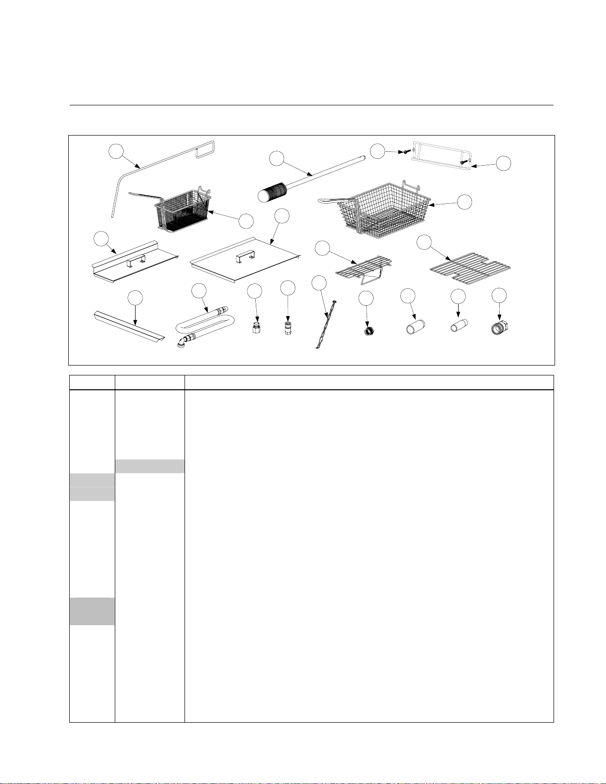
2.1 Accessories
6
1
8
10
11
7
9
3
12
13
16
ITEM PART # COMPONENT
1 803-0271 Basket, Twin
2 803-0099 Basket, Full (cannot be used with basket lifts)
3 803-0133 Basket Support Rack, Dual Vat
4 803-0132 Basket Support Rack, Full Vat
* 803-0136 Basket Support Screen, Full Vat (screen w/handle used in place of Item 4)
5 Coupling, Gas Line Female Quick Disconnect
810-0070 ¾-inch
810-0073 1-inch
6 803-0197 Cleanout Rod, 27-inch (Fryer's Friend)
7 803-0209 Brush, Frypot
8 806-3407 Cover, Frypot, Dual Vat
9 806-3068 Cover, Frypot, Full Vat
* 826-0993SP Handle Kit, Frypot Cover (includes handle and screws)
10 910-7443 Connecting Strip, Frypot
11 810-0478 Gas Line, 1-Inch Dormont Flexible
806-1698SP 36-Inch (for gas line only (w/o Items 12 and 13), use 810-0088)
806-1699 48-Inch (for gas line only (w/o Items 12 and 13), use 810-0085)
12 810-0074 Quick-Disconnect Fitting, 1-Inch Male
13 810-0073 Quick-Disconnect Fitting, 1-Inch Female
14 810-2793 Hanger, Basket
15 809-0171 Thumbscrew, ¼-20 X 1⅜-inch Basket Hanger
* 809-0921 Spacer, Basket Hanger
16 826-0900 Kit, Chain Restraint
17 826-1045 Bushing, Flexible Gas Line (813-0032)
15
2
4
17
18
19
14
5
2-1
Page 2

ITEM PART # COMPONENT
18 812-1378 Drain Extension, Non-Filter Full Vat Fryer
19 812-1374 Drain Extension, Non-Filter Dual Vat Fryer
* 803-0219 Pad, McDonald’s FPIII Universal Filter
* 803-0170 Filter Pack, Paper – 100 Sheets
* 803-0002 Powder, Filter – 80 Packages
* 826-1157 Kit, Fuse and Fuse Puller (2 Fuses)
* Not illustrated.
2-2
Page 3
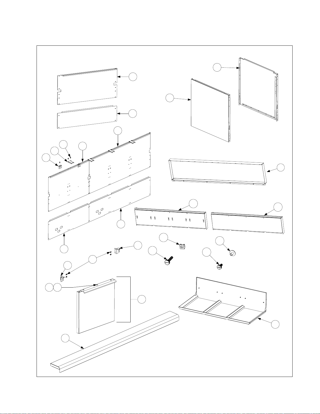
2.2 Cabinetry
2.2.1 Backs, Doors, Flue Caps, Sides, Top Caps, Standoffs and Cap-N-Splash Assemblies
18
1
17
2
5
9
8
7
4
13
1211
3
20
15
6
22
14
23
9
25
24
16
10
21
19
2-3
Page 4

r
r
)
)
)
)
t
p
)
r
r
r
r
r
r
r
r
t
t
)
f
f
f
f
f
ITEM PART # COMPONENT
1 Back, Single Uppe
210-6581 Stainless Steel
200-6581 Cold Rolled Steel
2 Back, Single Lowe
210-6580 Stainless Steel
200-6580 Cold Rolled Steel
3 Back, Double Upper (for 2-, 4-, and 5-station fryers – does not include Items 7-9
210-6542 Stainless Steel
200-6540 Cold Rolled Steel
4 Back, Double Lower (for 2-, 4-, and 5-station fryers – does not include Items 7-9
210-6541 Stainless Steel
200-6539 Cold Rolled Steel
5 Back, Triple Upper (for 3- and 5-station fryers – does not include Items 7-9
210-6545 Stainless Steel
200-6547 Cold Rolled Steel
6 Back, Triple Lower (for 3- and 5-station fryers – does not include Items 7-9
210-6544 Stainless Steel
200-6546 Cold Rolled Steel
7 200-6419 Clip, Flue Suppor
8 200-5865 Support, Flue Ca
9 826-1374 Screw, #10 X ½-inch Hex Washer Head (Pkg. of 25
10 106-3966 Door, Left or Right (Left shown – move handle to bottom for Right)
11 809-0266 Screw, #10 X ½-inch Phillips Truss Head
12 210-6816 Handle, Door
13 823-4729 Hinge, Left Door Uppe
14 823-4730 Hinge, Right Door Uppe
15 Flue Cap-Stainless Steel (Does not include Item 27)
210-5549 Single Fryer
106-3579 2-Station Frye
106-3537 3-Station Frye
106-3535 4-Station Fryer
106-3536 5-Station Fryer
16 Flue Cap - Aluminized Steel for use with Cap-N-Splash
210-5525 Single Fryer
106-3539 2-Station Frye
106-3540 3-Station Frye
106-3542 4-Station Frye
106-3543 5-Station Frye
17 Side, Left Standard Cabine
211-6510SP Stainless Steel
201-6633 Enameled Steel
18 Side, Right Standard Cabine
212-6510SP Stainless Steel
202-6633 Enameled Steel
19 Top Cap (Cap for 5-staion fryer shown
824-1310 Single Fryer (use 824-1689
824-1357 2-Station Fryer (use 824-1690
823-4702 3-Station Fryer (use 823-5733
823-4704 4-Station Fryer (use 824-5734
823-4706 5-Station Fryer (use 824-5735
or fryers mfd. After 3.15.06)
or fryers mfd. After 3.15.06)
or fryers mfd. After 3.15.06)
or fryers mfd. After 3.15.06)
or fryers mfd. After 3.15.06)
2-4
Page 5

ITEM PART # COMPONENT
20 Standoffs
200-6582 Single Fryer
200-6553 2-Station Fryer
200-6554 3-Station Fryer
200-6555 4-Station Fryer
200-6556 5-Station Fryer
21 Cap-N-Splash Assemblies
823-3066 Single Fryer
823-3067 2-Station Fryer
823-3068 3-Station Fryer
823-3070 4-Station Fryer
823-3069 5-Station Fryer
22 826-1351 Nut Retainer, ¼-20 (Pkg. of 10 – for basket hanger thumbscrew) for Std. Fluecap
23 809-0171
24 809-0402 Thumbscrew, ¼-20 x ½-inch (for use on Cap-N-Splash Assembly)
25 809-0535 T-Nut, ¼-20 x 7/16-inch (for use on Cap-N-Splash Assembly)
Thumbscrew, ¼-20 x
1⅜-inch (for use on Standard Fluecap)
2-5
Page 6
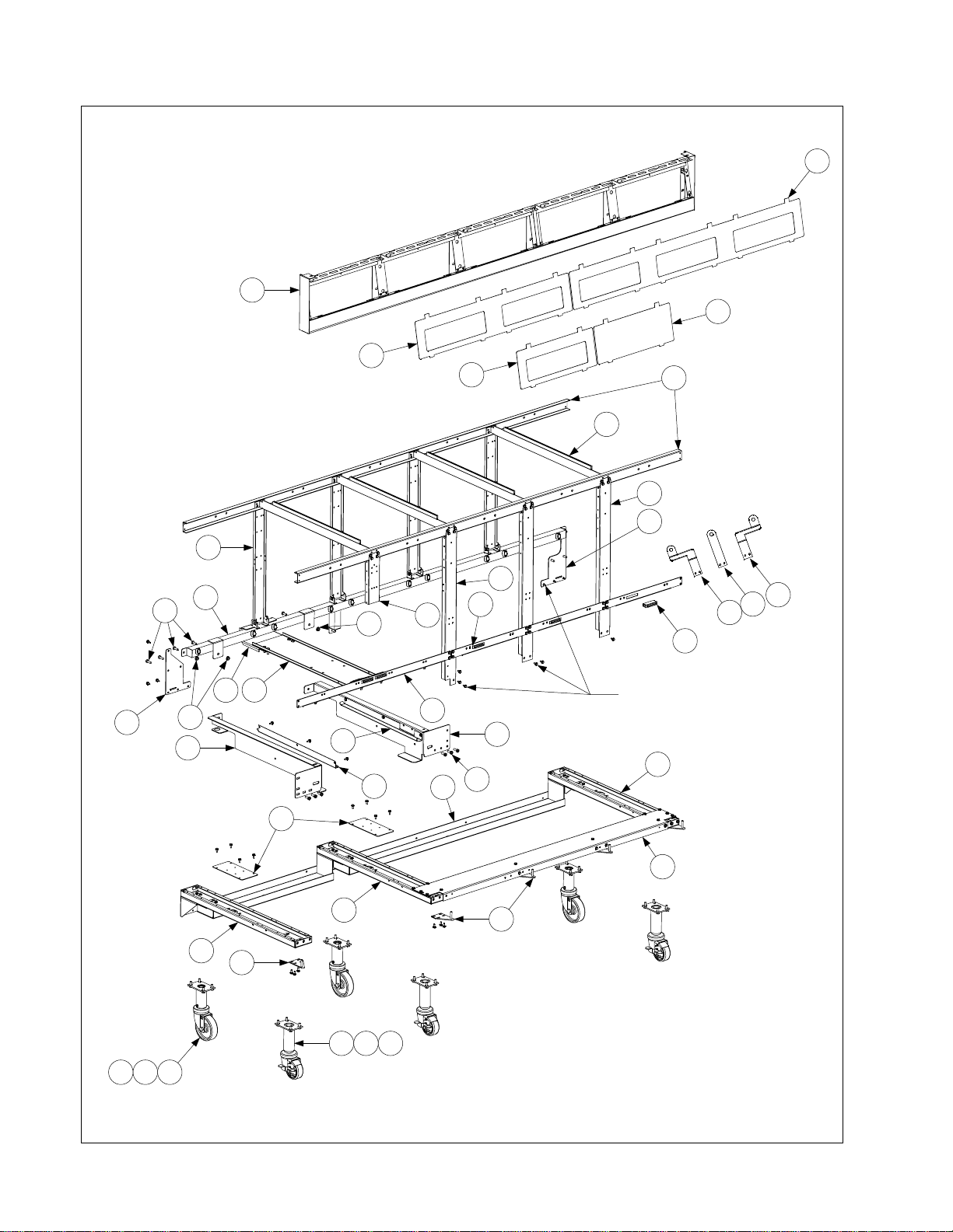
2.2.2 Filter Cabinet Bases, Casters, Framing, and Related Components
The 5-station cabinet illustrated is typical of
all BIPH52/55 Series Gas filter cabinets. All
base and framing components used in
BIPH52/55 Gas filter cabinets are identified,
but not all components are used in every
configuration.
1
2
11
15
31
34
10
3
5
4
7
9
12
6
8
19
37
36
35
14
All cabinet screws, unless otherwise
17
16
18
34
20
23
22
13
21
31
27
indicated, are #10 x 1/2-inch Hex
Washer Head P/N 826-1374, sold in
packages of 25.
25
Not shown is the Base Shield
P/N 200-6036
24
26
25
25
28
See Page 2-4 for upper hinges.
29
NOTE: 2- and 3-station
fryers have 4 casters; 4- and
5-station fryers have 6.
30 32 33
333231
2-6
Page 7

ITEM PART # COMPONENT
1 106-4303 Frame, Control Panel, Two Station, (use 106-5221SP mfd. After 3.15.06)
106-4304 Three-Station, Standard (use 106-5018SP mfd. After 3.15.06)
106-4305 Four-Station, Standard (use 106-5019 mfd. After 3.15.06)
106-4306 Five-Station, Standard (use 106-5020 mfd. After 3.15.06)
2 210-5819 Bezel, Two-Controller
3 210-6698 Bezel, Three-Controller
4 210-5046 Bezel, One-Controller
5 210-5623 Bezel, Blank
6 900-7730 Brace, Cabinet Top Two-Station
900-9430 Three-Station
900-9318 Four-Station
200-5474 Five-Station
7 200-5478 Divider, Cabinet
8 200-9217 Post, Cabinet Front
9 200-6031 Post, Filter Door
10 200-2235 Bracket, Component Box Support
11 200-6550 Post, Cabinet Rear
12 200-1953 Brace, Front Cabinet
13 200-6507 Support, Cross Cabinet
14 810-1105 Magnet, Door
15 Manifold, Rear (for units w/ filtration also see page 2-17 for additional parts)
810-2890 Two-Station
810-2891 Three-Station
810-2892 Four-Station
810-2893 Five-Station
16 200-2213 Bracket, Rear Bridge Support
17 200-9818 Bridge, Filter Pump
18 200-6326 Gusset, Left Rear Corner
19 200-7031 Gusset, Right Rear Corner
20 201-9467 Support, Left Filter Rail
21 202-9467 Support, Right Filter Rail
22 823-4651 Slide, Filter Pan Lid Left
23 823-4652 Slide, Filter Pan Lid Right
24 200-2102 Brace, Side Channel
25 823-4653 Channel, Side Base
26 Channel, Front Base (not used in two-station fryers)
200-6609 Three-Station
200-6610 Four-Station
200-5473 Five-Station
27 823-4510 Channel, Rear Base Two-Station
823-4630 Three-Station
823-4629 Four-Station
823-4628 Five-Station
28 823-4732 Hinge, Lower Left
29 823-4733
Hinge, Lower Right (attach to Hinge Bracket 200-5478 in 4- & 5-station fryers)
30 810-0944 Caster w/Brake, 8½ to 10-inch Adjustable (3-inch wheel)
31 810-0327 Caster w/o Brake, 8½ to 10-inch Adjustable (4-inch wheel)
32 809-0953 Bolt, ¼-20 x ¾-inch Hex Head
33 809-0191 Washer, ¼-inch Lock
34 809-0417 Nut, ¼-20 Flange
35 201-6720 Mount, Rear Flush Rod Offset, Left
36 200-6697 Mount, Rear Flush Rod Holder, Center
37 202-6720 Mount, Rear Flush Rod Offset, Right
* 200-6036 Base Shield
2-7
Page 8
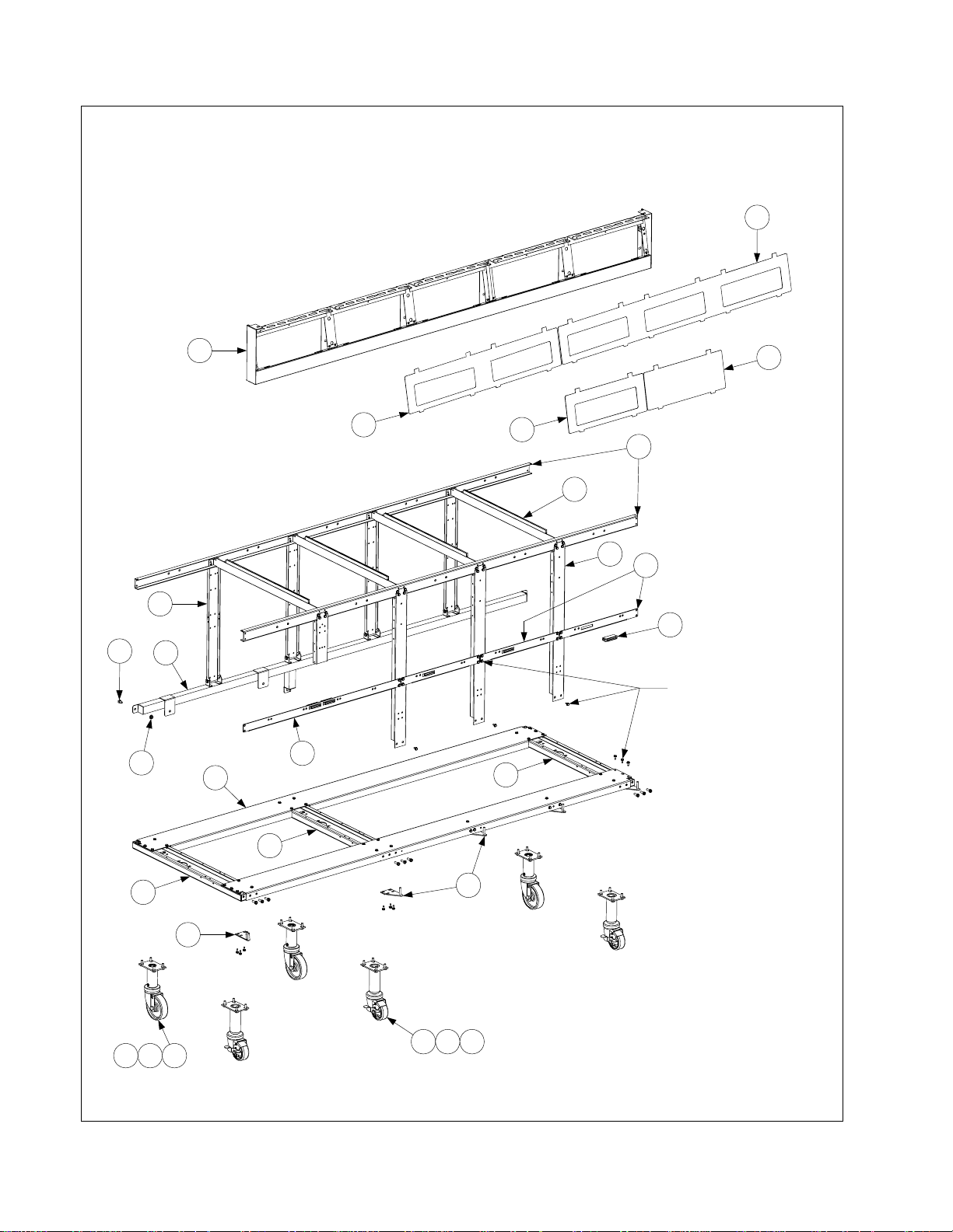
2.2.3 Non-Filter Cabinet Bases, Casters, Framing, and Related Components
The 5-station cabinet illustrated is typical of
all MPH52/55 Series Gas non-filter cabinets.
All base and framing components used in
MPH52/55 Series Gas non-filter cabinets are
identified, but not all components are used in
every configuration.
3
1
2
10
22
14
2
6
7
8
11
13
All cabinet screws,
5
unless otherwise
indicated, are #10 x 1/2inch Hex Washer Head
P/N 826-1374, sold in
packages of 25.
24
17
12
15
15
15
18
See Page 2-4 for upper hinges.
19
NOTE: 2- and 3-station
fryers have 4 casters; 4- and
5-station fryers have 6.
232221
20 22 23
2-8
Page 9

ITEM PART # COMPONENT
1 Frame, Control Panel
106-4302 Single-Station, Standard (use 106-5016 mfd. After 3.15.06)
106-4303 Two-Station, Standard (use 106-5221SP mfd. After 3.15.06)
106-4304 Three-Station, Standard (use 106-55018SP mfd. After 3.15.06)
106-4305 Four-Station, Standard (use 106-5019 mfd. After 3.15.06)
106-4306 Five-Station, Standard (use 106-5020 mfd. After 3.15.06)
2 210-5819 Bezel, Two-Controller
3 210-6698 Bezel, Three-Controller
4 210-5046 Bezel, One-Controller
5 210-5623 Bezel, Blank
6 Brace, Cabinet Top
200-5498 Single Fryer
900-7730 Two-Station
900-9430 Three-Station
900-9318 Four-Station
200-5474 Five-Station
7 200-5478 Divider, Cabinet
8 200-6614 Post, Cabinet Front
9 200-2235 Bracket, Component Box Support
10 200-6550 Post, Cabinet Rear
11 200-1953 Brace, Front Cabinet
12 200-6507 Support, Cross Cabinet
13 810-1105 Magnet, Door
14 Manifold, Rear (not present in single fryers)
823-3223 Two-Station
823-4691 Three-Station
823-4693 Four-Station
823-4694 Five-Station
15 823-4653 Channel, Side Base
16 Channel, Front Base
200-6616
200-6623
200-6624
Single Fryer (also used as rear base channel in single-station fryers)
Two-Station (also used as rear base channel in single-station fryers)
Three-Station (also used as rear base channel in single-station fryers)
200-6625 Four-Station
200-6627 Five-Station
17 Channel, Rear Base
200-6626 Four-Station
200-6628 Five-Station
18 823-4732 Hinge, Lower Left
19 823-4733
Hinge, Lower Right (attach to Bracket 200-5478 in 3-, 4-, & 5-station fryers)
20 810-0944 Caster w/Brake, 8½ to 10-inch Adjustable (3-inch wheel)
21 810-0327 Caster w/o Brake, 8½ to 10-inch Adjustable (4-inch wheel)
22 809-0953 Bolt, ¼-20 x ¾-inch Hex Head
23 809-0191 Washer, ¼-inch Lock
24 809-0417 Nut, ¼-20 Flange
2-9
Page 10
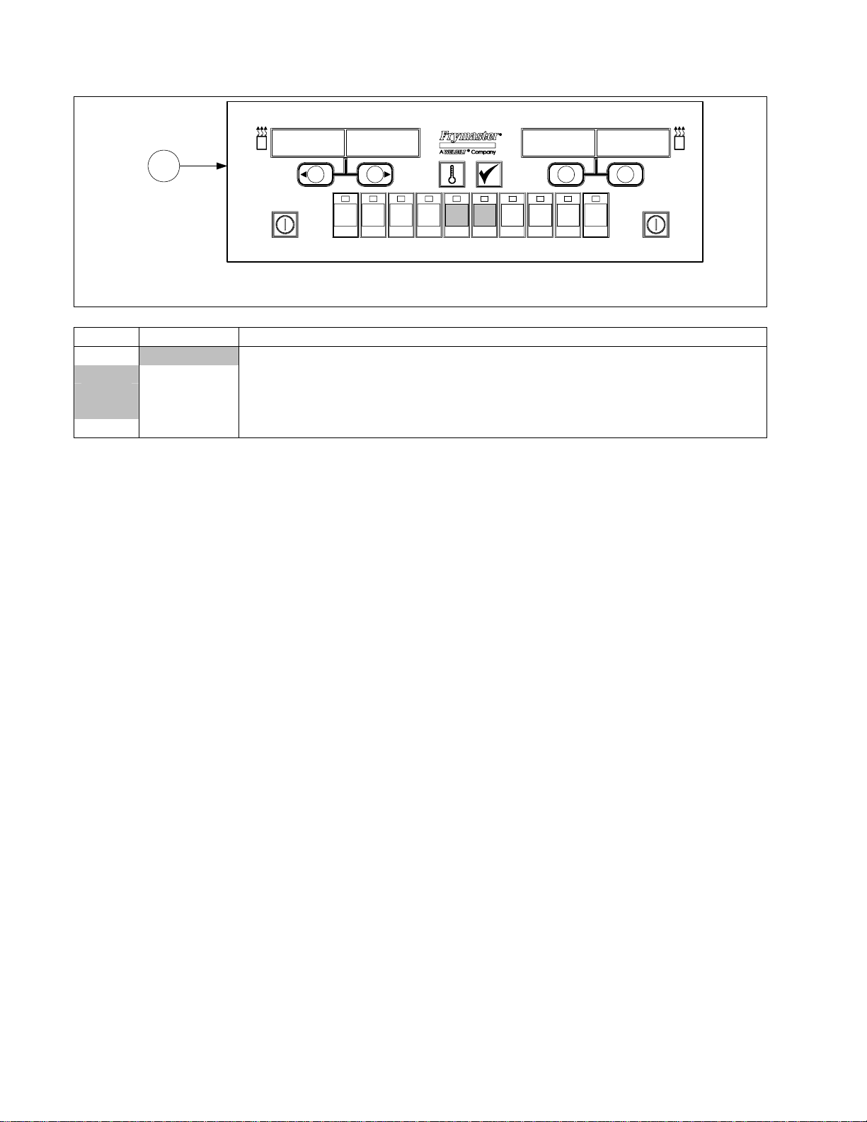
2.3 Controllers and Associated Components
1
1 1 2
2
1234567890
ABC DEF GHI JKL MNO PQR STU VWX
JC
YZ
-
-
*
ITEM PART # COMPONENT
1 Computer, McDonald’s M2000 Gas Fryer
106-1269 Full Vat (Domestic U.S.) Can also be programmed for Dual Vat.
106-0672 Full Vat (CE) Can also be programmed for Dual Vat.
106-5950
Full Vat (CE) Can also be programmed for Dual Vat (Australia Only)
* 807-3520 M2000 Speaker
* Not illustrated.
2-10
Page 11
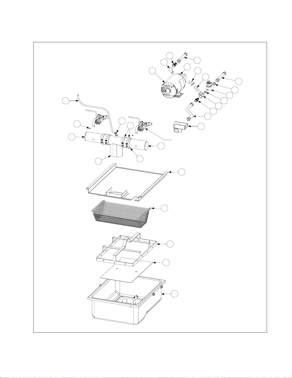
2.4 Drain, Filtration, and Oil Return System Components
2.4.1 Filtration System Components
15
21
27
12
8
7
6
11
10
See Page 2-13
7
9
5
22
26
24
25
17
16
15
14
13
20
19
18
4
3
2
1
2-11
Page 12

ITEM PART # COMPONENT
1 106-2617SP Pan Assembly, FootPrint Pro Filter (incl. O-rings, rollers, nuts & crumb tray)
826-1980 Pan Assembly – No Screen
823-3930SP Pan Assembly, Filter
813-0568 Plug, ⅛-inch NPT Socket Head
826-1392 O-Ring (two required) (Pkg. of 5)
810-2198 Roller, Filter Pan
826-1372 Nut, ¼-20 Hex Flange (Pkg. of 10)
826-1979 Kit- Contains four each of roller 810-2198 and ¼-20 Flange Nut 809-0059
2 200-2240 Screen, Sana Grid
3 810-2183
810-2091
4 823-5146 Tray, Filter Pan Crumb
5 823-5249 Lid, Filter Pan
6 823-4678 Tube, 3-inch Center Drain (Open Both Ends)
823-4708 Closed One End
7 Tube, 3-inch Round Drain (823-4625 illustrated)
823-4638 Dual Vat, Long (one end closed)
823-4640 Dual Vat, Long (open both ends)
823-4624 Dual Vat, Short (one end closed)
823-4642 Dual Vat, Short (open both ends)
823-4639 Full Vat, Long (one end closed)
823-4641 Full Vat, Long (open both ends)
823-4625 Full Vat, Short (one end closed)
823-4643 Full Vat, Short (open both ends)
200-6473 Spreader, Long (open both ends, no drain valve connection)
200-6474 Spreader, Short (open both ends, no drain valve connection)
8 809-0247 Nut, 8-32 Hex Keps
9 816-0625 Sleeve, Round Drain Connector
10 809-0969 Clamp, Round Drain Sleeve
11 810-2493 Elbow, ¼-inch NPT X 90° Tube Compression
12 811-1071 Tube, ¼-inch OD Teflon Manifold Vent
13 823-3879 Suction Tube, FootPrint Pro Female
14 810-1055 Flexline, ⅝-inch OD X 11.50-inch
15 810-1668 Adapter, ⅝-inch OD X ½-inch Male
16 813-0530 Tee, ½-inch X ½-inch X ¼-inch Reducing
17 813-0838 Nipple, ¼-inch NPT Close
18 807-2484 Solenoid Valve w/Female Pins
19 810-2773 Adapter, ½-inch OD Flare x ¼-inch NPT
20 810-2787 Flexline, ½-inch OD X 5.00-inch
21 813-0165 Elbow, ½-inch NPT X 90° Street
22 810-1680 Flexline, ⅝-inch OD x 11.50-inch
23 813-0265 Nipple, ½-inch NPT X 2.50-inch
24 813-0342 Elbow, ½-inch NPT X 45° Street
25 813-0298 Nipple, ½-inch NPT X 2.00-inch
26 826-1264 Pump and Gasket Kit (for gasket only, order P/N 816-0093)
27 Motor and Gasket Kit, 50/60 Hz (for gasket only, order P/N 816-0093)
826-1785 100V
826-1712 115V
826-1756 208V
826-1270 220-240V
826-1755 250V
Ring, Filter Pad Hold-Down Ring (11.20-inch X 19.10-inch)
Ring, Filter Paper Hold-Down Ring (13.47-inch X 21.41-inch)
2-12
Page 13

2.4.2 Drain Valves and Associated Components
2-13
Page 14

ITEM PART # COMPONENT
1 810-1569 Valve Assembly, 1.25-inch Full-Vat Non-Filter Drain (includes handle)
* 810-1427 Lock Pin Handle for 1.25-inch Valve Assembly
2 806-7915SP Valve Assembly, 1-inch Left Dual-Vat Non-Filter Drain (complete assembly)
3 806-7916SP Valve Assembly, 1-inch Right Dual-Vat Non-Filter Drain (complete assembly)
4 809-0589 Nut, ½-13 2-Way Lock (used on non-filter drain valves)
5 810-1568 Handle w/Lock Pin, Left Drain Valve
6 810-1567 Handle w/Lock Pin, Right Drain Valve
7 106-1106SP Valve Assembly, 1.25-inch Full-Vat w/Filter Drain (complete assembly)
8 106-3512 Valve Assembly, 1-inch Left Dual-Vat w/Filter Drain (complete assembly)
9 106-3513 Valve Assembly, 1-inch Right Dual-Vat w/Filter Drain (complete assembly)
10 816-0135 O-Ring, Drain Valve
11 810-1018 Valve, 1.25-inch Drain
12 806-8137 Bracket Assembly, Drain Safety Switch
13 816-0220 Insulation, Drain Safety Switch
14 807-2103 Microswitch, Lever Activated
15 900-2841 Cover, Full-Vat Drain Safety Switch
16 826-1366 Nut, 4-40 Hex Keps (Pkg. of 25)
17 824-1602 Handle, Full-Vat Drain Valve
18 900-2936 Retainer, Full-Vat Drain Valve Nut
19 809-0540 Nut, ½-13 2-Way Lock
20 816-0677 Grip, Drain Valve Handle
21 200-6496 Support, 3-inch Drain Tube
22 810-1114 Valve, 1-inch Dual-Vat w/Filter Drain
23 809-0196
24 810-1165
Washer, ⅜-inch Flat
Washer, ⅜-inch Teflon
25 900-2934 Retainer, Dual-Vat Drain Valve Nut
26 809-0539
Nut, ⅜-16 2-Way Lock
27 823-4578 Handle, Left Dual-Vat Drain Valve
28 823-4577 Handle, Right Dual-Vat Drain Valve
29 901-2348 Cover, Left Dual-Vat Drain Safety Switch
30 902-2348 Cover, Right Dual-Vat Drain Safety Switch
31 106-2671 Bracket Assembly, Left Dual-Vat Drain Safety Switch
32 106-2672 Bracket Assembly, Right Dual-Vat Drain Safety Switch
33 810-1338 Valve, 1-Inch Dual-Vat Non-Filter Drain
34 Drain Valve Extension
812-1226SP Full-Vat (1.25-inch)
812-1227 Dual-Vat (1-inch)
35 816-0639 Grip, Drain Valve Handle 5/16” x 3”
2-14
Page 15

2.4.3 Rear Flush Oil Return Line Components
2-15
Page 16

ITEM PART # COMPONENT
1 Valve Assembly, Microswitch and Ball Valve
106-3452 Valve Rear Flush Assembly, Left Side
106-3453 Valve Rear Flush Assembly, Right Side
2 810-2493 Elbow, 90° x ¼-inch
3 809-0601 Clip, Rod End Clevis
4 Shaft, Rear Flush Valve
211-6701
212-6701
For use in Left
For use in Right
oil return valve assemblies.
oil return valve assemblies.
5 Handle, Rear Flush Valve
901-2772
902-2772
For use in Left
For use in Right
oil return valve assemblies.
oil return valve assemblies.
6 813-0165 Elbow, 90° x ½-inch Street
7 813-0087 Nipple, 1½-inch BM NPT
8 810-2201 Valve, ½-inch Ball
* 900-2935 Oil Return Valve Nut Retainer
9 810-1668
Adapter, Male
⅝-inch Flexline to ½-inch NPT Male
9a 810-2786 Adaptor, ½-inch Flare x ½ -inch NPT
10 807-2484 Valve, ¼-inch NPT Solenoid Vent
11 Manifold, BIPH52 Rear Flush Oil Return
810-2890 Two-Station Fryer
810-2891 Three-Station Fryer
810-2892 Four-Station Fryer
810-2893 Five-Station Fryer
12 813-0156 Cap, ½-inch Pipe
13 816-0220 Insulation, Rear Flush Switch
14 807-4101 Microswitch, Lever Activated
15 826-1366 Nut, 4-40 Keps Hex (Pkg. of 25)
16 826-1359 Screw, 4-40 x ¾-inch Slotted Round Head (Pkg. of 25)
17 809-0250 Nut, 6-32 Keps Hex
18 200-8745 Cover, Microswitch Rear Flush
19 807-0125 Bushing, .50 ID Heyco SB-750-8 Nylon
20 813-0700 Nipple, ¼ NPT x 3-inch
21 816-0643 Grip, Oil Return Handle
22 810-1067
Flexline,
⅝-inch OD x 8.50-inch Oil Return
23 810-2787 Flexline, ½” x 5.00-inch Pump to Oil Return Manifold
24 810-1680
Flexline,
⅝-inch OD x 6.50-inch Oil Return Manifold to Pump
25 811-1071 Tube, ¼-inch OD Teflon Manifold Vent
2-16
Page 17

2.5 Electronics and Electrical Components
(for Controllers, Page 2-10)
2.5.1 Component Boxes
Australian Units
28
12
2112
10
8 21
16 21 23 25
2417
201571
3
2
2
Hong Kong Units
2221106
9 19 22
6 10 21 22
16 21 23 25
13
2417
5
2
18
2
27
U.S., Canadian, and Mexican Units
23
21
28
3
See NOTE 1 on Page 2-23.
1 7 15 20
11
Left module is not present in full-vat units.
25
13
24 17
28
16 21 23 25
2417
201571
CE and Non-CE Export Units Except Austraila and Hong Kong
11
2615
22199
22
10
5
4
19
2-17
Page 18

ITEM PART # COMPONENT
1 810-1164 Block, One-Piece Screwless Terminal
2 200-5996 Box, One-Piece Component
3 807-1926 Bushing, .875-inch Split
4 807-3483 Cable, 21-inch Ignition H50/H52 –For 807-3366/3365 Modules
* 826-2024 Cable, Ignition - 1 wire / 1 rajah
* 826-1721 Cable, Ignition – 2 wire / 2 rajah
5 807-3484 Connector, Rajah
6 106-0531SP Fuse Assembly, Inline
7 816-0217 Insulation, Terminal Block Paper
8 807-2971 Ignition Module, Australian
9 807-1006 Ignition Module, CE and Non-CE export (except Australia, Canada, HK, Mexico)
10 807-3366† Ignition Module, Dual-Spark Full-Vat (U.S., Canadian, HK, and Mexican units)
807-3365† Ignition Module, Single-Spark Ignition Module Dual-vat (U.S., Canadian, HK,
and Mexican units)
11 826-2264 Interface Board Kit; U.S., CE and non-CE (except Hong Kong)
106-6706 Interface Board SMT, U.S., CE and non-CE (except Hong Kong)
807-4330 Sound Device/Speaker Adapter Harness SMT
807-4343 Wire Harness, SMT Interface Board to Ignition Module
12 106-0387 Interface Board, Australian
13 806-4973 Interface Board, Hong Kong
14 807-1359 Mount, Ty-Wrap
15 826-1366 Nut, 4-40 Keps Hex (Pkg. of 25)
16 809-0250 Nut, 6-32 Keps Hex
17 807-0833
Relay, DPDT 5A 12VDC Latch (See NOTE 1.)
18 806-2071 Cable, 15-pin Computer to Interface Board
19 809-0441 Screw, #8 X 1½-inch Hex Washer Head
20 826-1359 Screw, 4-40 X ¾-inch Slotted Round Head (Pkg. of 25)
21 809-0098 Screw, 6-32 X 1¼-inch Slotted Round Head
22 826-1346 Spacer, Ignition Module (Pkg. of 10)
23 810-2763 Spacer, Interface Board
24 810-2243 Spring, Relay Retaining
25 826-1337 Tab, ¼-inch Terminal (Pkg. of 5)
26 807-1948 Ty-Wrap
27 806-6085SP Wire Assembly, Ignition Module
28 807-3843 Fuse 3A 250V Domestic
807-3293
Fuse 5A 125V International Only
* 807-1200 Ignition Wire, 27”
* 807-1878 Ignition Wire, 19”
* 807-3520 Sound Device, High Output
* Not illustrated.
† For Dual-vat units, use 807-3365 Single Spark Ignition Module (see NOTE 1).
NOTE 1: U.S., Canadian, Hong Kong, and Mexican units use two different modules depending upon the
configuration of the frypot. Dual-Vat units use two 807-3365 Single-Spark Ignition Modules. Full-Vat units
use one 807-3366 Dual-Spark Ignition Module. Also, in full-vat units, only one latch relay (Item 17) is used,
located in the lower right socket.
2-18
Page 19

2.5.2 Transformer Boxes
2-19
Page 20

2.5.2 Transformer Boxes Continued
6
19 30
19 30
19 30
35
13 30
36
19 30
5
2
33323126
3011
392225
38
282414
G
7
8
37
9
19 30
19 30
35
13 30
36
19 30
5
2
33323126
3016
3011
182225
282414
F
7
8
37
2-20
Page 21

ITEM PART # COMPONENT
Box Assembly, Transformer
A 106-1380 100-120V FMPH152/155, FMPH352/355, FMPH452/455
B 106-3818 100-120V BIPH 252/255, BIPH 452/455, FMPH252/255
C 106-4888 100-120V BIPH 352/355
D 106-3819 208-240V BIPH 252/255 and BIPH 452/455 CE/Non-CE Export
E 106-3817 250V BIPH 252 and BIPH 452 CE/Non-CE Export
F 106-3824 208-240V BIPH 352/355 CE/Non-CE Export
G 106-3823 250V BIPH 352/355 CE/Non-CE Export
1 106-3820 Cable Assembly, Transformer Box #1
2 106-3821 Cable Assembly, Transformer Box #2
3 106-1011 Cable Assembly, Transformer Box Line
4 106-1016 Cable Assembly, Transformer Box Filter Pump
5 106-3827 Cable Assembly, Transformer Box #1 (On Box G this PN# becomes 106-4898)
6 106-4990 Cable Assembly, Transformer Box Line
7 106-3825 Cable Assembly, Transformer Box #3
8 106-3826 Cable Assembly, Transformer Box Filter Pump
9 106-3316 Cable Assembly, Transformer Box Line
10 200-1415 Cover, Transformer Box
11 200-6721 Plate, Strain Relief
12 200-2318 Cover, Transformer Box Cable Plate
13 807-0012 Relay, 18 Amp 1/3-HP 24V Coil
14 807-0070 Terminal, Ground Lug
15 807-0155 Connector, 9-Pin Male
16 807-0680 Transformer, 208-240V/24VAC 50/60Hz 20VA
17 807-0800 Transformer, 100-120V/24VAC 50/60Hz 50VA ( On Box C PN# is 807-1238)
18 807-1973 Terminal, Post
19 807-1999 Transformer, 208-240V V/F Dual Voltage
20 807-2176 Transformer, 100-120V V/F Dual Voltage
21 809-0052 Nut, 10-24 Hex
22 826-1362 Nut, 1/4-20 Hex (Pkg. of 10)
23 826-1363 Screw, 8-32 X 1/2-inch Slotted Truss Head (Pkg. of 25)
24 809-0123 Screw, 10-24 X 3/4-inch Slotted Truss Head
25 826-1389 Screw, 1/4-20 X 3/4-inch Hex Head (Pkg. of 10)
26 826-1366 Nut, 4-40 Keps Hex (Pkg. of 25)
27 809-0247 Nut, 8-32 Keps Hex
28 826-1376 Nut, 10-32 Keps Hex (Pkg. of 10)
29 826-1359 Screw, 4-40 X 3/4-inch Slotted Round Head (Pkg. of 25)
30 809-0360 Screw, #8 X 3/8-inch Hex Washer Head
31 809-0656 Screw, 4-40 X 3/8-inch Slotted Round Head
32 810-1164 Block, One-Piece Screwless Terminal
33 816-0217 Insulation, Terminal Block Paper
34 824-1242 Box, Transformer BIPH252, 452
35 824-1301 Box, Transformer BIPH352, 552
36 807-1683 Relay, Hood 12V DC
37 807-0157 Connector, 6-Pin Male
38 816-0219 Paper, CE Triple Terminal Block Insulating
39 810-1163 Block, 3 Places Screwless Terminal
40 106-4894 Cable Assembly, Transformer Box Filter Pump
41 106-4893 Cable Assembly, Transformer Box Line
Continued on Next Page
2-21
Page 22

Continued from Previous Page
ITEM PART # COMPONENT
* WIR 0623 Wire Assembly, PH52 Hood Relay
* WIR0634 Wire Assembly, FPP50 Transformer/Filter Box (used in Item E)
* WIR0635 Wire Assembly, FPPH350 Transformer Filter Box (used in Item G)
* WIR0439 Wire Assembly, Transformer Box (used in Items B, D, and E)
* WIR0447 Wire Assembly, Transformer Box (used in Item A)
* WIR0580 Wire Assembly, Transformer Box (used in Item C)
* Not illustrated
2.5.3 High-Limit Thermostat and Temperature Probe
1
3
2
ITEM PART # COMPONENT
1 826-1177
2 806-4206 Temperature Probe
3 210-0681 Probe Guard
Thermostat Assembly, HE FM High-Limit 425°F/218°C
2-22
Page 23

2.7 Frypots and Associated Components
2.7.1 Full-Vat Frypot Components
2-23
Page 24

ITEM PART # COMPONENT
1 106-1019SP Flue Assembly, Full-Vat
2 200-0936 Back, Left Full-Vat Combustion Chamber
3 200-0937 Back, Right Full-Vat Combustion Chamber
4 200-2227 Retainer, Full-Vat Upper Insulation
5 826-1372 Nut, ¼-20 Flange Hex (Pkg. of 10)
6 826-1371 Screw, #8 X ½-inch Hex Head Drill Point (Pkg. of 25)
7 809-0362 Screw, #8 X 1¼-inch Hex Washer Head Drill Point
8 826-1383 Washer, Steel (Pkg. of 5)
9 809-0500 Screw, #10 X ½-inch Hex Washer Head 410 SS
10 809-0804 Nut, ¼-20 Keps Hex
11 826-1340 Spacer, .25-inch X 1.187-inch (Pkg. of 10)
12 810-0500 Spacer, .25-inch X .9375-inch
13 826-1072 Burner, Universal Replacement
14 812-0355 Insulation, Full-Vat Lower Rear
15 812-0356 Insulation, Burner Sight Glass
16 816-0577 Insulation, Burner
17 812-0404 Insulation, Left or Right Front Seal
18 812-0457 Insulation, Full-Vat Lower Front
19 812-0706 Insulation, Upper Burner Rail
20 812-0993 Insulation, Upper Oil Zone
21 812-1029 Insulation, Combustion Chamber Side
22 814-0048SP Glass, Burner Sight
23 816-0057 Gasket, Plenum
24 816-0560 Insulation, Full-Vat Upper Front
25 816-0561 Insulation, Left or Right Outer Front
26 823-0969 Plenum, Full-Vat
27 823-1777 Side and Rail, Left Full-Vat Combustion Chamber
28 823-3323SP Frypot, Full-Vat 439 SS
29 823-3142 Side and Rail, Right Full-Vat Combustion Chamber
30 823-3304 Front, Full-Vat Right Combustion Chamber
31 823-3305 Front, Full-Vat Left Combustion Chamber
32 823-3315 Retainer, Left Full-Vat Lower Front Insulation
33 823-3316 Retainer, Right Full-Vat Lower Front Insulation
34 824-0863 Retainer, Left Full-Vat Upper Insulation
35 824-0864 Retainer, Right Full-Vat Upper Insulation
36 900-1031 Retainer, Burner Sight Glass
37 900-1049 Retainer, Plenum Gasket
38 900-1221 Retainer, Rear Insulation
39 900-1515 Brace, Upper Oil Zone Insulation
40 900-4452 Retainer, Combustion Chamber Side Insulation
41 930-0818 Bracket, Flue to Frypot
42 900-4253 Strip, Fluecap Retainer
* 910-2474 Pot-to-Pot Gap Clip
* 106-1049SP Frypot Assembly Full-Vat w/RF HE (NAT)
* 106-1050SP Frypot Assembly Full-Vat w/RF HE (PRO)
* 106-1053 Frypot Assembly Full-Vat w/RF HE (MFG)
* 826-0929 Insulation Kit, Complete Full-Vat
* 826-0931 Insulation Kit, Burner Full-Vat
* Not Illustrated
2-24
Page 25

2.7.2 Dual-Vat Frypot Components
2-25
Page 26

ITEM PART # COMPONENT
1 106-1018SP Flue Assembly, Dual-Vat
2 200-0941 Back, Dual-Vat Combustion Chamber
3 200-2229 Retainer, Dual-Vat Upper Insulation
4 826-1372 Nut, ¼-20 Flange Hex (Pkg. of 10)
5 809-0360
Screw, #8 X ⅜-inch Hex Head
6 809-0362 Screw, #8 X 1¼-inch Hex Washer Head Drill Point
7 826-1383 Washer, Steel (Pkg. of 5)
8 809-0500 Screw, #10 X ½-inch Hex Washer Head 410 SS
9 809-0804 Nut, ¼-20 Keps Hex
10 826-1340 Spacer, .25-inch X 1.187-inch (Pkg. of 10)
11 810-0500 Spacer, .25-inch X .9375-inch
12 826-1072 Burner, Universal Replacement
13 812-0354 Insulation, Dual-Vat Lower Rear
14 812-0356 Insulation, Burner Sight Glass
15 816-0577 Insulation, Burner
16 812-0404 Insulation, Left or Right Front Seal
17 812-0458 Insulation, Dual-Vat Lower Front
18 812-0688 Insulation, Flue Collector
19 812-0706 Insulation, Upper Burner Rail
20 812-0993 Insulation, Upper Oil Zone
21 812-1029 Insulation, Combustion Chamber Side
22 814-0048SP Glass, Burner Sight
23 816-0057 Gasket, Plenum
24 816-0558 Insulation, Dual-Vat Lower Front
25 816-0559 Insulation, Dual-Vat Upper Front
26 823-0970 Plenum, Dual-Vat
27 823-2822 Side and Rail, Left Dual-Vat Combustion Chamber
28 823-2823 Side and Rail, Right Dual-Vat Combustion Chamber
29 823-3324SP Frypot, Dual-Vat 439 SS
30 823-3302 Front, Dual-Vat Combustion Chamber
31 823-3303 Retainer, Dual-Vat Lower Front Insulation
32 824-0865 Retainer, Left Dual-Vat Upper Insulation
33 824-0866 Retainer, Right Dual-Vat Upper Insulation
34 900-0914 Retainer, Lower Rear Insulation
35 900-1031 Retainer, Burner Sight Glass
36 900-1049 Retainer, Plenum Gasket
37 900-1515 Brace, Upper Oil Zone Insulation
38 900-4452 Retainer, Combustion Chamber Side Insulation
39 930-0818 Bracket, Flue to Frypot
40 900-4253 Strip, Fluecap Retainer
41 824-0541 Riser, DV Pot Divider W/A
* 910-2474 Pot-to-Pot Gap Clip
* 106-1079SP Frypot Assembly Dual-Vat w/RF HE (NAT)
* 106-1080SP Frypot Assembly Dual-Vat w/RF HE (PRO)
* 106-1070 Frypot Assembly Dual-Vat w/RF HE (MFG)
* 826-0930 Insulation Kit, Complete Dual-Vat
* 826-0932 Insulation Kit, Burner Dual-Vat
* Not Illustrated
2-26
Page 27

2.8 Gas Supply and Combustion System Components
21
3
4
5
See Section 2.7 for burners
and burner isulation part
numbers.
6
PH252/255 Full Vat Gas Manifold
(Typical)
The example illustrated is typical of
BIPH52/55-MPH52/55 Fryer Gas
Manifolds. Each manifold is assembled
from standard 1/2-, 3/4-, and 1-inch
NPT black iron pipe nipples, elbows,
tees, plugs, and unions, which may be
locally aquired.
See Section 2-9 for details of
gas valves and related
components.
2-27
Page 28

ITEM PART # COMPONENT
1 Ignitor (includes gasket 816-0059, which may be ordered separately)
826-0981 Natural Gas (G20, G25)
826-0982 Propane (G30, G31)
826-1002 Manufactured Gas
2 826-1371 Screw, #8 X ½-inch Hex Head (Pkg. of 25)
3 Blower Assembly, Combustion Air (includes harness and Items 4, and 5)
106-2996SP 100V 50/60 Hz (Left)
106-2999SP 100V 50/60 Hz (Right)
106-2994SP 115V 50/60 Hz. (Left)
106-2997SP 115V 50/60 Hz (Right)
106-2995SP 208-240V 50/60 Hz (Left)
106-2998SP 208-240V 50/60 Hz (Right)
106-3000SP 230V 50/60 Hz CE (Left)
106-3001SP 230V 50/60 Hz CE (Right)
4 816-0554 Cover, Blower Motor (component of all blowers listed above)
5 809-0938 Screw, 10-32 X ⅝-inch Philips Truss Head (secures Item 4 to Item 3)
* 806-8806SP Harness Assembly, Blower Motor (component of all blowers listed
above)
6 Orifice, Burner
812-1137 1.95 mm Propane/Butane (G30, G31) (0-4999 Ft, 0-1524 M) (CE)
810-1221 2.00 mm Propane/Butane (0-4999 Ft, 0-1524 M) (Japan only)
810-0386 2.10 mm Propane/Butane (0-4999 Ft, 0-1524 M)
810-0413 2.16 mm Propane/Butane (G30, G31) (5000-6999 Ft, 1525-2133 M)
812-1028 2.20 mm Propane/Butane (G30, G31) (7000-10,999 Ft, 2134-3352 M)
812-1134 3.10 mm Natural Gas (G20, G25) (0-4999 Ft, 0-1524 M) (Japan only)
810-0403 3.40 mm Natural Gas (G20, G25) (0-4999 Ft, 0-1524 M)
810-0437 3.60 mm Natural Gas (G20, G25) (5000-6999 Ft, 1525-2133 M)
812-1144 3.65 mm Natural Gas (G20, G25) (7000-8999 Ft, 2134-2743 M)
812-1145 3.70 mm Natural Gas (G20, G25) (9000-10,999 Ft, 2744-3352 M)
810-0642 5.95 mm Manufactured Gas (0-4999 Ft, 0-1524 M)
* 826-1196 Conversion Kit, Natural Gas (G20, G25) to Propane/Butane (G30, G31)
CE only
* 826-1197 Conversion Kit, Propane/Butane (G30, G31) to Natural Gas (G20, G25)
CE only
* 807-2263 Switch, Air Pressure (use 807-2262 in units with 100VAC power supply)
* Not illustrated.
2-28
Page 29

2.9 Gas Valves and Associated Components
5
NOTE: Items 5, 6, 7, and 8
6
are used with both CE and
Non-CE gas valves.
7
8
15
NOTE: The gas tube and
enrichment tube fittings are
assembled in varying
configurations depending
upon the location of the
valve and whether the
associated frypot is a fullor a dual-vat pot.
13
9
11
1
12
13
4
14
16
18
17
Non-CE Gas Valve Assembly
(Typical)
2 3
10
19
20
CE Gas Valve Assembly
(Typical)
11
10
23
21
22
2-29
Page 30

ITEM PART # COMPONENT
1 Valve, Non-CE Gas
826-1122 Natural Gas (G20, G25)
826-1120 Kit Natural Gas w/ flexlines and hardware
826-1123 Propane Gas (G30, G31)
826-1121 Kit, Propane Gas w/ flexlines and hardware
2 810-1715 Valve, CE Gas (G20, G25, G30, G31)
3 810-1041 Accessory Kit (contains parts to adapt Item 2 to specific fryer configura-
tion)
4 810-0691 Tube, ⅛-inch Vent
5 810-0494 Ferrule (Nut), Orifice
6 810-1355 Gas Line, ⅜-inch OD X 15-inch SS Flexible
7 810-1354 Gas Line, ⅜-inch OD X 12-inch SS Flexible
810-1353 Gas Line, ⅜-inch OD X 9-inch SS Flexible (Used on some split pot ap-
plications)
8 811-0800 Tube, ⅛-inch OD X 12.5-inch Enrichment (cut and form to fit)
9 813-0301 Tee, ¼-inch Male NPT to ⅜-inch Tube
10 813-0302 Elbow, ¼-inch Male NPT to ⅜-inch Tube 90° (used on DV valve)
11 813-0304 Bushing, ½-inch NPT to ¼-inch NPT Flush Reducing
12 813-0405 Nipple, ⅛-inch NPT X 2-inch
13 813-0378 Fitting, ⅛-inch NPT Cross
14 813-0340 Adapter, ⅛-inch NPT to ⅛-inch Tube
15 813-0154 Plug, ⅛-inch NPT Hex Head Pipe
16 810-1176 Tap, ⅛-inch NPT Pressure
17 813-0377 Tee, ⅛-inch NPT Female
18 813-0354 Elbow, ⅛-inch NPT X ⅛-inch Tube Compression
19 813-0016 Nipple, ⅛-inch NPT X Close
20 810-1006 Bushing, ¼-inch NPT to ⅛-inch NPT Reducing
21 813-0495 Tee, ¼-inch Male NPT to Female NPT
22 810-1025 Connector, ¼-inch Male NPT to ⅜-inch Tube
23 810-1026 Tee, ¼-inch Male NPT to Female NPT Street
2-30
Page 31

2.10 Wiring Assemblies and Harnesses
Filter Associated Wiring
2
1
ITEM PART # COMPONENT
1 807-3584 Cable, Filter Lower 9-Pin Plug to 807-2001 15-Pin (C2) Connector
2 807-2001 Cable, 810-3584 15-Pin C2 Connector to Component Box
1
2
Gas Valve Wiring
ITEM PART # COMPONENT
1 806-3941SP Harness, Full Vat Gas Valve
2 806-3940SP Harness, Dual Vat Gas Valve
3 806-9678SP Plug Assembly, CE Gas Valve
3
2-31
Page 32

Main Wiring Harnesses
U.S. and Non-CE harness (shown)
has two unterminated wires.
Unterminated wires.
CE harness has two unterminated
wires plus two additional wires with
push-on terminals.
ITEM PART # COMPONENT
807-1978 U.S. and Non-CE Export Main Wiring Harness
807-2168 CE Main Wiring Harness
1
2
4
3
ITEM PART # COMPONENT
1 806-6083 Power Cord, 120V w/Grounding Plug 5 wire (w/Ring Terminals, no
Clamp)
2 807-1696 Power Cord, CE
3 807-1560 Strain Relief
4 106-1020 Pump Motor to Transfer Box Wiring Assembly
2-32
Page 33

Transformer Box Cable Assemblies
11
5
10
8 9
2 3 4
1
7
6
2-33
Page 34

ITEM PART # COMPONENT
1 106-1011 Cable Assembly, Transformer Box Line (See NOTE 1)
2 106-1016 Cable Assembly, Transformer Box to Filter Pump (See NOTE 2)
3 106-3821 Cable Assembly, Transformer Box #2 Position (See NOTE 7)
4 106-3820 Cable Assembly, Transformer Box #1 Position (See NOTE 3)
5 106-3316 Cable Assembly, Transformer Box Line (See NOTE 4)
6 106-4990 Cable Assembly, Transformer Box Line (See NOTE 8)
7 106-3825 Cable Assembly, Transformer Box #3 Position (See NOTE 5)
8 106-3826 Cable Assembly, Transformer Box to Filter Pump (See NOTE 5)
9 106-3827 Cable Assembly, Transformer Box #1 Position (See NOTE 5)
10 106-4894 Cable Assembly, Transformer Box to Filter Pump (See NOTE 6)
11 106-4893 Cable Assembly, Transformer Box Line (See NOTE 6)
NOTE 1: Item 1 is used in transformer boxes B and D on page 2-19.
NOTE 2: Item 2 is used in transformer boxes A, B and D on page 2-19.
NOTE 3: Item 4 is used in transformer boxes A, B, D and E on page 2-19.
NOTE 4: Item 5 is used in transformer boxes C and F on pages 2-19 and 2-20.
NOTE 5: Items 7, 8 and 9 are used in transformer boxes C, F and G on pages 2-19 and 2-20.
NOTE 6: Items 10 and 11 are used in transformer box E on page 2-19.
NOTE 7: Item 3 is used in transformer boxes A-F on pages 2-19 and 2-20.
NOTE 8: Item 6 is used in transformer box G on page 2-20.
2-34
Page 35

2.11 Miscellaneous Connectors and Terminals
1 2
6
11
7 9 10
3
8
12
4
13
ITEM PART # COMPONENT
1 807-1068 2-Pin Female
2 807-0158 6-Pin Female
3 807-0156 9-Pin Female
4 807-0159 12-Pin Female
5 807-0875 15-Pin Female
6 807-1067 2-Pin Male
7 807-0157 6-Pin Male
8 807-0155 9-Pin Male
9 807-0160 12-Pin Male
10 807-0804 15-Pin Male
11 826-1341 Terminal, Female Split Pin (Pkg of 25)
12 826-1342 Terminal, Male Split Pin (Pkg of 25)
13 807-2518 Plug, Mate-N-Lock (Dummy Pin)
* Not illustrated.
5
2-35
 Loading...