

Page 1
This equipment chapter is to be
installed in the Fryer Section of the
Equipment Manual.
MANUFACTURED
BY
SERVICE MANUAL
FRYMASTER BIPH14/MPH14 SERIES
ELECTRIC FRYER
Do Not Store or use gasoline or other
flammable vapors and liquids in the
vicinity of this or any other appliance.
FOR YOUR SAFETY
P.O. BOX 51000
SHREVEPORT, LOUISIANA 71135-1000
PHONE: 1-318-865-1711
TOLL FREE: 1-800-551-8633
1-800-24 FRYER
FAX: 1-318-688-2200
TABLE OF CONTENTS
WARRANTY STATEMENT...................................................................................................Page i
SERVICE PROCEDURES....................................................................................................Page 1-1
1.1 General .................................................................................................................Page 1-1
1.2 Replacing a Computer..........................................................................................Page 1-1
1.3 Replacing Component Box Components .............................................................Page 1-2
1.4 Replacing a Temperature Probe or High-Limit Thermostat..................................Page 1-3
1.5 Replacing a Heating Element...............................................................................Page 1-4
1.6 Replacing Contactor Box Components ................................................................Page 1-6
1.7 Replacing a Frypot................................................................................................Page 1-7
1.8 Built-in Filtration System Service Procedures ......................................................Page 1-9
1.9 Interface Board Diagnostic Charts........................................................................Page 1-13
1.10 Wiring Diagrams ...................................................................................................Page 1-14
PARTS LIST..........................................................................................................................Page 2-1
Frymaster L.L.C., 8700 Line Avenue 71106
P.O. Box 51000, Shreveport, Louisiana 71135-1000
PHONE 318-865-1711 FAX 318-219-7135
PRINTED IN THE UNITED STATES SERVICE HOTLINE 1-800-24-FRYER MAY 2006
*8196011*
Page 2
IF, DURING THE WARRANTY PERIOD, THE CUSTOMER USES A PART FOR THIS ENODIS EQUIPMENT OTHER THAN AN UNMODIFIED NEW OR
RECYCLED PART PURCHASED DIRECTLY FROM FRYMASTER/DEAN, OR ANY OF ITS AUTHORIZED SERVICE CENTERS, AND/OR THE PART
BEING USED IS MODIFIED FROM ITS ORIGINAL CONFIGURATION, THIS WARRANTY WILL BE VOID. FURTHER, FRYMASTER/DEAN AND ITS
AFFILIATES WILL NOT BE LIABLE FOR ANY CLAIMS, DAMAGES OR EXPENSES INCURRED BY THE CUSTOMER WHICH ARISE DIRECTLY OR
INDIRECTLY, IN WHOLE OR IN PART, DUE TO THE INSTALLATION OF ANY MODIFIED PART AND/OR PART RECEIVED FROM AN
UNAUTHORIZED SERVICE CENTER.
NOTICE
This appliance is intended for professional use only and is to be operated by qualified personnel only. A
Frymaster/Dean Factory Authorized Service Center (FASC) or other qualified professional should perform
installation, maintenance, and repairs. Installation, maintenance, or repairs by unqualified personnel may void
the manufacturer’s warranty. See Chapter 1 of this manual for definitions of qualified personnel.
NOTICE
NOTICE
This equipment must be installed in accordance with the appropriate national and local codes of the country
and/or region in which the appliance is installed. See NATIONAL CODE REQUIREMENTS in Chapter 2 of this
manual for specifics.
NOTICE TO U.S. CUSTOMERS
This equipment is to be installed in compliance with the basic plumbing code of the Building Officials and Code
Administrators International, Inc. (BOCA) and the Food Service Sanitation Manual of the U.S. Food and Drug
Administration.
NOTICE
Drawings and photos used in this manual are intended to illustrate operational, cleaning and technical
procedures and may not conform to onsite management operational procedures.
NOTICE TO OWNERS OF UNITS EQUIPPED WITH COMPUTERS
U.S.
This device complies with Part 15 of the FCC rules. Operation is subject to the following two conditions: 1)
This device may not cause harmful interference, and 2) This device must accept any interference received,
including interference that may cause undesired operation. W hile this device is a verified Class A device, it has
been shown to meet the Class B limits.
CANADA
This digital apparatus does not exceed the Class A or B limits for radio noise emissions as set ou t by the ICES003 standard of the Canadian Department of Communications.
Cet appareil numerique n’emet pas de bruits radioelectriques dep assany les limites de classe A et B prescrites
dans la norme NMB-003 edictee par le Ministre des Communcations du Canada.
DANGER
Improper installation, adjustment, maintenance or service, and unauthorized alterations or modifications can
cause property damage, injury, or death. Read the installation, operating, and service instructions thoroughly
before installing or servicing this equipment.
DANGER
The front ledge of this appliance is not a step! Do not stand on the appliance. Serious injury can result from
slips or contact with the hot cooking oil/shortening.
DANGER
Do not store or use gasoline or other flammable liquids or vapors in the vicinity of this or any other appliance.
DANGER
The crumb tray in fryers equipped with a filter system must be emptied into a fireproof container at the end of
frying operations each day. Some food particles can spontaneously combust if left soaking in certain shortening
material.
WARNING
Do not bang fry baskets or other utensils on the fryer’s joiner strip. Th e strip is present to seal the joint between
the fry vessels. Banging fry baskets on the strip to dislodge shortening will distort the strip, adversely affecting
its fit. It is designed for a tight fit and should only be removed for cleaning.
Page 3

WARRANTY STATEMENT
Frymaster, L.L.C. makes the following limited warranties to the original purchaser only for this
equipment and replacement parts:
A. WARRANTY PROVISIONS - FRYERS
1. Frymaster L.L.C. warrants all components against defects in material and workmanship for a
period of one year.
2. All parts, with the exception of the frypot, heating elements and fuses, are warranted for one
year after installation date of fryer.
3. If any parts, except fuses, become defective during the first year after installation date,
Frymaster will also pay straight-time labor costs to replace the part, plus up to 100 miles/160
km of travel (50 miles/80 km each way).
B. WARRANTY PROVISIONS - FRYPOTS
If a frypot develops a leak within seven years after installation, Frymaster will, at its option,
either replace the entire battery or replace the frypot, allowing up to the maximum time per the
Frymaster time allowance chart hours of straight-time labor plus up to 100 miles/160 km of
travel (50 miles/80 km each way) to change the frypot.
C. WARRANTY PROVISIONS - HEATING ELEMENTS
1. Frymaster L.L.C. warrants the heating elements against defective material or workmanship
for a period of three years from the original installation date, parts only.
2. This warranty does not cover ancillary components, including the hi-limit, temperature
probe, and contactors.
D. WARRANTY PROVISIONS - COOKING COMPUTER
1. Frymaster L.L.C. warrants the M-2000 Cooking Computer against defective material or
workmanship for a period of one year from the original installation date, parts and labor.
Replacements for defective units during the second year will fall under warranty; however,
labor will not. Replacements are available during the third year at a reduced rate.
2. Replacement M-2000 Cooking Computers will be warranted for the first and second years
only. Replacements are available during the third year at a reduced rate. When a computer is
replaced under warranty, the replaced computer carries the remaining original warranty only.
3. During this warranty period, Frymaster will, at its option, repair or replace defective cooking
computer returned with new and functionally operative units.
4. For replacement of defective computers under warranty, call your local Frymaster Factory
Authorized Service Center. All computers replaced under the Frymaster exchange program
are covered by a one-year (parts only) warranty.
i
Page 4

E. PARTS RETURN
All defective in-warranty parts must be returned to a Frymaster Authorized Factory Service
Center within 60 days for credit. After 60 days, no credit will be allowed.
F. WARRANTY EXCLUSIONS
This warranty does not cover equipment that has been damaged due to misuse, abuse, alteration,
or accident such as:
• improper or unauthorized repair (including any frypot which is welded in the field);
• failure to follow proper installation instructions and/or scheduled maintenance procedures as
prescribed in your MRC cards. Proof of scheduled maintenance is required to maintain the
warranty;
• improper maintenance;
• damage in shipment;
• abnormal use;
• removal, alteration, or obliteration of either the rating plate or the date code on the heating
elements;
• operating the frypot without shortening or other liquid in the frypot;
• no fryer will be warranted under the seven-year program for which a proper start-up form has not
been received.
This warranty also does not cover:
• transportation or travel over 100 miles/160 km (50 miles/80 km each way), or travel over two
hours;
• overtime or holiday charges;
• consequential damages (the cost of repairing or replacing other property which is damaged), loss
of time, profits, use or any other incidental damages of any kind.
There are no implied warranties of merchantability or fitness for any particular use or purpose.
ii
Page 5
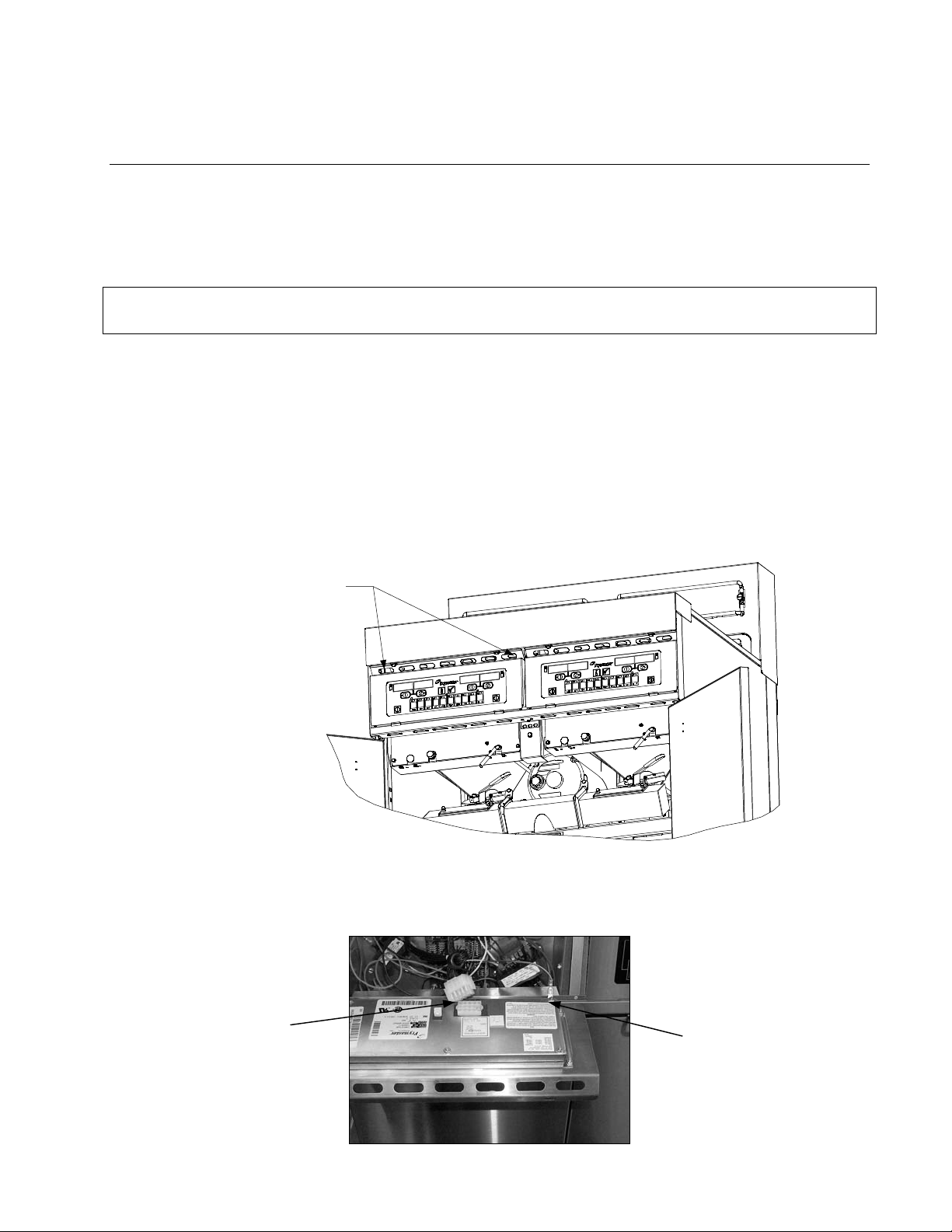
BIPH14/MPH14 SERIES ELECTRIC FRYERS
Ground Wire Terminal
15-Pin Connector
CHAPTER 1: SERVICE PROCEDURES
1.1 General
Before performing any maintenance on your Frymaster fryer, disconnect the fryer from the electrical
power supply.
To ensure the safe and efficient operation of the fryer and hood, the electrical plug for the 120-volt
line, which powers the hood, must be fully engaged and locked in its pin and sleeve socket.
When electrical wires are disconnected, it is recommended that they be marked in such a way as to
facilitate re-assembly.
1.2 Replacing a Computer
1. Before removing controllers from Euro-look models (round top-cap and drains), slide the metal
bezel up to release the bottom tabs; then, remove it.
2. Remove the two screws from the upper corners of the control panel. The control panel is hinged
at the bottom and will swing open from the top.
Remove screws in upper
corners of control panel and
swing control panel down.
3. Unplug the wiring harness from the connector on the back of the computer and disconnect the
grounding wire from terminal adjacent to the connector. Remove the control panel assembly by
lifting it from the hinged slots in the control panel frame.
1-1
Page 6
4. Remove the controller from the control panel assembly and install the replacement computer.
Reinstall the control panel assembly by reversing steps 1 and 2.
1.3 Replacing Component Box Components
1. Remove the two screws from the upper corners of the control panel and allow the control panel
to swing down (see steps 1 and 2 of section 1.2 on preceding page).
2. Unplug the wiring harness from the 15-pin connector on the interface board and disconnect the
grounding wire from terminal adjacent to the 15-pin connector on the back of the controller.
Remove the control panel assembly by lifting it from the hinge slots in the control panel frame.
3. Disconnect the wiring from the component to be replaced, being sure to make a note of where
each wire was connected.
NOTE: If replacing the interface board, connectors J1 and J2 must also be disconnected from
the 12-pin connectors on the rear of the component box, directly behind the interface board.
4. Dismount the component to be replaced and install the new component, being sure that any
required spacers, insulation, washers, etc. are in place.
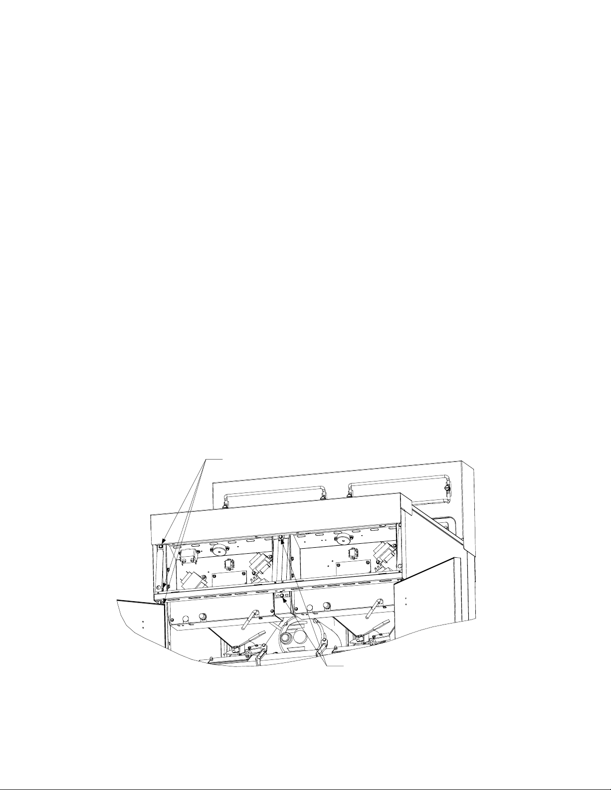
NOTE: If more room to work is required, the control panel frame and top cap assembly may be
removed by removing the hex head screws that secure it to the fryer cabinet (see illustration
below). If this option is chosen, all control panel assemblies must be removed per steps 1 and 2
above. The cover plate on the lower front of the component box may also be removed if desired.
Removing the component box itself from the fryer is not recommended due to the difficulty
involved in disconnecting and reconnecting the oil-return valve rods, which pass through
openings in the component box.
Remove these three
screws at each end.
Remove these two screws
from the center supports.
Removing the Control Panel Frame and Top Cap Assembly
1-2
Page 7
5. Reconnect the wiring disconnected in step 3, referring to your notes and the wiring diagrams on
the fryer door to ensure that the connections are properly made. Also, verify that no other wiring
was disconnected accidentally during the replacement process.
6. Reverse steps 1 and 2 to complete the replacement and return the fryer to service.
1.4 Replacing a Temperature Probe or High-Limit Thermostat
1. Remove the filter pan and lid from the unit. Drain the frypots into an oil disposal unit (MSDU)
or other appropriate metal container.
DANGER
DO NOT drain more than one full frypot or two split frypots into the MSDU at one time.
2. Disconnect the fryer from the electrical power supply and reposition it to gain access to the rear
of the fryer.
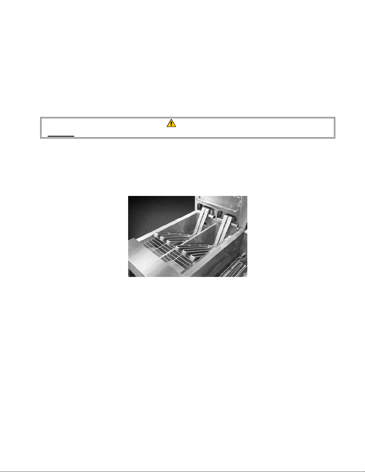
3. Remove the tilt housing and back panels from the fryer. The tilt housing must be removed first in
order to remove the upper back panel. To remove the tilt housing, raise the elements and allow
them to rest on the basket support racks as shown in the photo below.
Next, remove the hex head screws from the rear edge of the housing. The housing can then be
lifted straight up and off the fryer. Lift up on the upper back panel to disengage the tabs on its
upper corners from the cutouts in the fryer frame.
4. Disconnect the wire harness at connector C6 and, using a pin pusher, disconnect the probe leads
or high-limit leads from the connector.
5. If replacing a temperature probe, remove the screw securing the probe bracket to the element
and slide the bracket off the element and probe. Pull the probe out of the tilt housing assembly,
install the replacement probe, and reattach the element bracket. Secure the upper portion of the
probe with a replacement metal wire tie.
1-3
Page 8
Probe Leads
Probe Bracket
Metal Wire Tie
If replacing a high-limit thermostat, unscrew the thermostat to be replaced. Apply Loctite™ PST
567 or equivalent sealant to the threads of the replacement and screw it securely into the frypot.
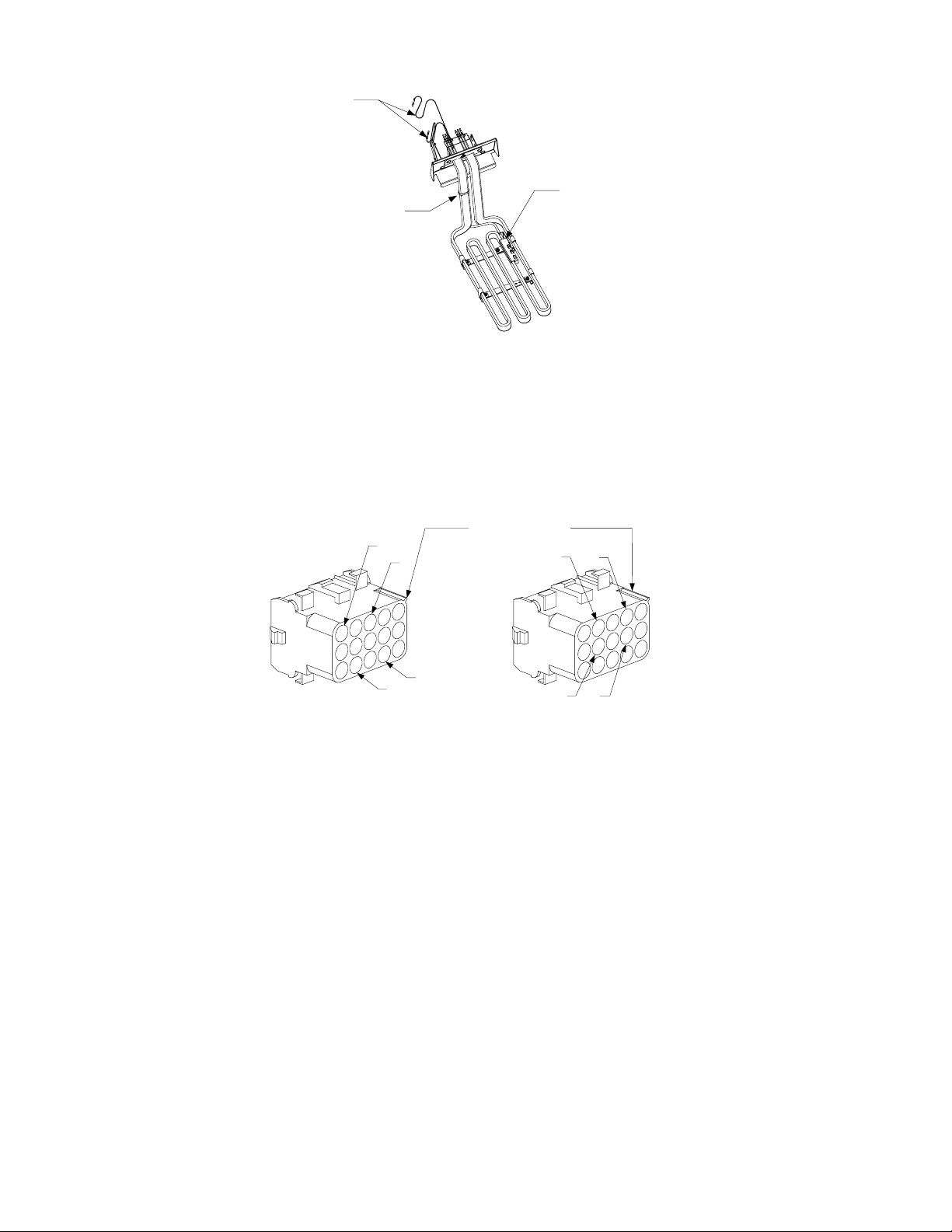
6. If a temperature probe was replaced, insert the probe leads into the connector (see left
illustration below). For full-vat units or the right half of a dual-vat unit, the red lead goes into
position 6 and the white into position 7. For the left half of a dual-vat unit, the red lead goes into
position 12 and the white into position 13. NOTE: Right and left refer to the fryer as viewed
from the rear.
Rib marks Position 1
13
7
10
4
6
12
Probe Lead Positions High-Limit Lead Positions
11
5
If a high-limit thermostat was replaced, insert the leads into the connector (see right illustration
above). For full-vat units or the right half of a dual-vat unit, the leads go into positions 4 and 5
of the connector. For the left half of a dual-vat unit, the leads go into positions 10 and 11. In
either case, polarity does not matter. NOTE: Right and left refer to the fryer as viewed from the
rear.
7. Reinstall the back panels and tilt housing to complete the installation, then reverse steps 1 and 2
to return the fryer to service.
1.5 Replacing a Heating Element
1. Perform steps 1-3 of section 1.4, Replacing a Temperature Probe.
2. On dual-vat fryers, and on full-vat fryers where the temperature probe is attached to the element
being replaced, disconnect the wire harness containing the probe wiring (connector C6). Using a
pin pusher, disconnect the probe wires from the connector.
1-4
Page 9
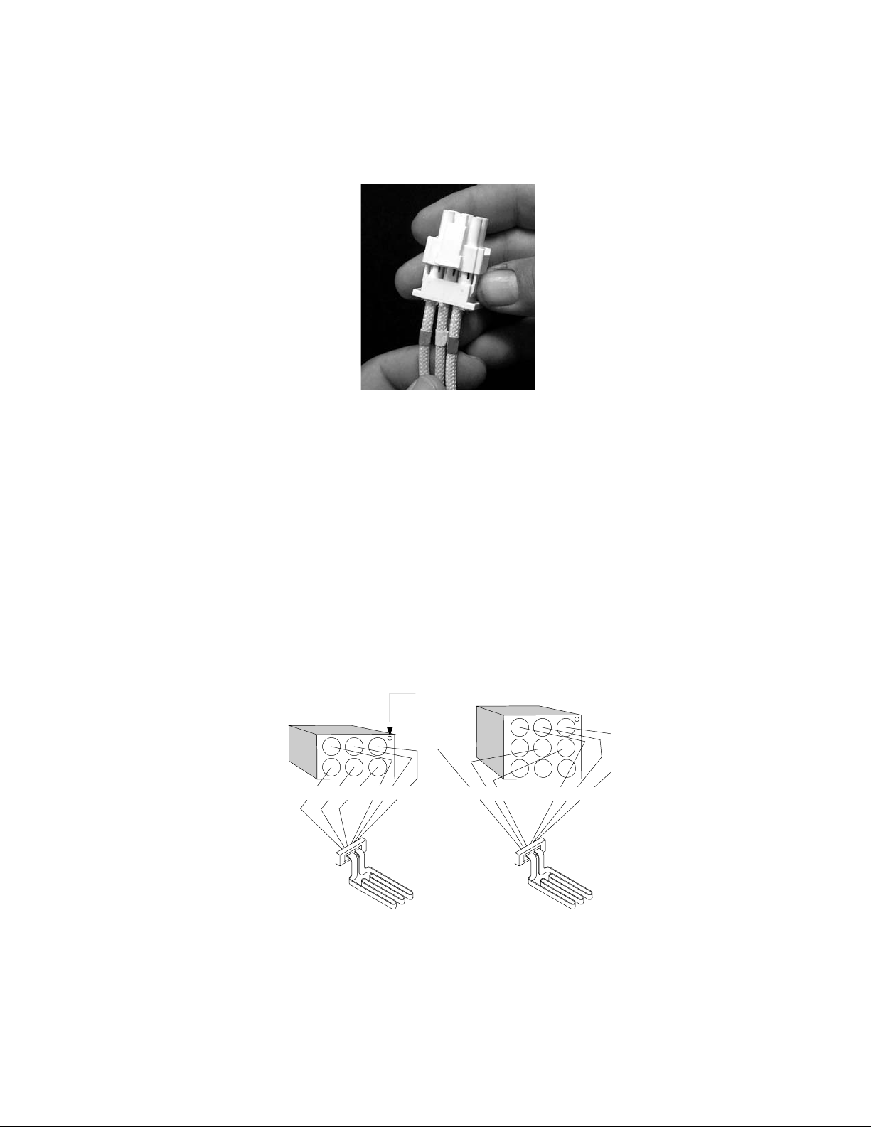
3. On the front of the contactor box, disconnect the 6-pin connector for the left element (as viewed
from the front of the fryer) or the 9-pin connector for the right element and pull the harness out
through the rear of the fryer. Press in on the tabs on each side of the connector while pulling
outward on the free end to extend the connector and release the element leads (see photo below).
Pull the leads out of the connector and out of the plastic wire loom.
4. Raise the element to the full up position and disconnect the element springs.
5. Remove the nuts and machine screws that secure the element to the tilt plate assembly and pull
the element out of the frypot. NOTE: Full-vat elements consist of two dual-vat elements
clamped together. For full-vat units, remove the element clamps before removing the nuts and
machine screws that secure the element to the tilt plate assembly.
6. If applicable, recover the probe bracket and probe from the element being replaced and install
them on the replacement element, then install the replacement element in the frypot, securing it
with the nuts and screws removed in Step 5.
7. Route the element leads through the wire loom to prevent chafing and press the pins into the
connector in accordance with the diagram below, then close the connector to lock the leads in
place.
Pip marks Position 1
1
253
1
2
3
5
6
5L 4L6L 1L2L3L
6
4
5R 4R6R 1R2R3R
4
789
8. Insert the element connector into the receptacle on the front of the contactor box, ensuring that
the latches lock.
9. If disconnected in step 2, insert the temperature probe leads into the wiring harness connector
(see illustration below). For full-vat units or the right half of a dual-vat unit, the red lead goes
1-5
Page 10
into position 6 and the white into position 7. For the left half of a dual-vat unit, the red lead goes
into position 12 and the white into position 13. NOTE: Right and left refer to the fryer as
viewed from the rear.
13
7
Rib marks Position 1
6
12
10. If disconnected in step 2, reconnect connector C6 of the wiring harness.
11. Reconnect the element springs and lower the element back down onto the basket rack.
12. Reinstall the tilt housing and back panels, reposition the fryer under the exhaust hood, and
reconnect it to the electrical power supply.
1.6 Replacing Contactor Box Components
1. Remove the filter pan and lid from the unit. Drain the frypots into an oil disposal unit (MSDU)
or other appropriate metal container.
DANGER
DO NOT drain more than one full frypot or two split frypots into the MSDU at one time.
2. Disconnect the fryer from the electrical power supply.
3. Unplug the wiring harnesses from the contactor box to be serviced.
4. Remove the two screws that secure the box in place. NOTE: If you remove the screws from
both boxes at the same time, the boxes will jam against each other and neither can be removed.
Remove these screws to dismount the left contactor box.
The right contactor box is secured in a similar manner.
1-6
Page 11
5. Carefully lower the box to the floor and pull it out the front of the fryer. Remove the top cover
to access contactors and other components.
6. After performing necessary service, reverse steps 1-5 to return the fryer to operation.
1.7 Replacing a Frypot
1. Remove the filter pan and lid from the unit. Drain the frypots into an oil disposal unit (MSDU)
or other appropriate metal container.
DANGER
DO NOT drain more than one full frypot or two split frypots into the MSDU at one time.
2. Disconnect the fryer from the electrical power supply and reposition it to gain access to both the
front and rear.
3. On Euro-look models, slide the metal bezel up to release the bottom tabs; then, remove it.
4. On all models, remove the two screws from the upper corners of the control panels and allow
them to swing down (see illustration and photo on page 1-1).
5. Unplug the wiring harnesses and ground wires from the backs of the controllers. Remove the
controllers by lifting them from the hinge slots in the control panel frame.
6. Remove the tilt housing and back panels from the fryer. The tilt housing must be removed first in
order to remove the upper back panel. To remove the tilt housing, raise the elements and allow
them to rest on the basket support racks (see photo on page 1-3).
Next, remove the hex head screws from the rear edge of the housing. The housing can then be
lifted straight up and off the fryer. Lift up on the upper back panel to disengage the tabs on its
upper corners from the cutouts in the fryer frame.
7. Dismount the top cap by removing the hex head screws at each end that secure it to the control
panel frame.
8. Remove the hex head screw that secures the front of the frypot to the cabinet cross brace.
9. Remove the top-connecting strip that covers the joint with the adjacent frypot.
10. On standard models, unscrew the Teflon vent/vacuum-breaker tube fitting, open the drain tube
cleanout covers, unscrew the retainer nuts from the drain valve nipples, and remove the tube
assembly from the fryer.
On Euro-look models, unscrew the Teflon vent/vacuum-breaker tube fitting, unscrew the nut
located on the front of each section of drain tube, and remove the tube assembly from the fryer.
11. Remove the covers from the drain safety switch(es) and disconnect the switch wiring at the
switch(es).
1-7
Page 12
12. At the rear of the fryer, unplug the C6 connector and, using a pin pusher, disconnect the highlimit thermostat leads.
13. Disconnect the oil return flexline(s) at the frypot end(s).
14. Raise the elements to the full up position and disconnect the element springs.
15. Remove the machine screws and nuts that secure the tilt plate and element assembly to the
frypot. Carefully lift the tilt plate and element assembly from the frypot and secure it to the cross
brace on the rear of the fryer with wire ties or tape.
16. Carefully lift the frypot from the fryer and place it upside down on a stable work surface.
17. Recover the drain valve(s), oil return flexline connection fitting(s), and high-limit thermostat(s)
™
from the frypot. Apply Loctite
PST 567 or equivalent sealant to the threads of the recovered
parts and install them in the replacement frypot.
18. Carefully lower the replacement frypot into the fryer. Reinstall the hex head screw removed in
step 7 to attach the frypot to the fryer.
19. Position the tilt housing and element assembly in the frypot and reinstall the machine screws and
nuts removed in step 14.
20. Reconnect the oil return flexlines to the frypot, and replace aluminum tape, if necessary, to
secure heater strips to the flexlines.
21. Insert the high-limit thermostat leads disconnected in step 11 (see illustration on page 1-4 for pin
positions).
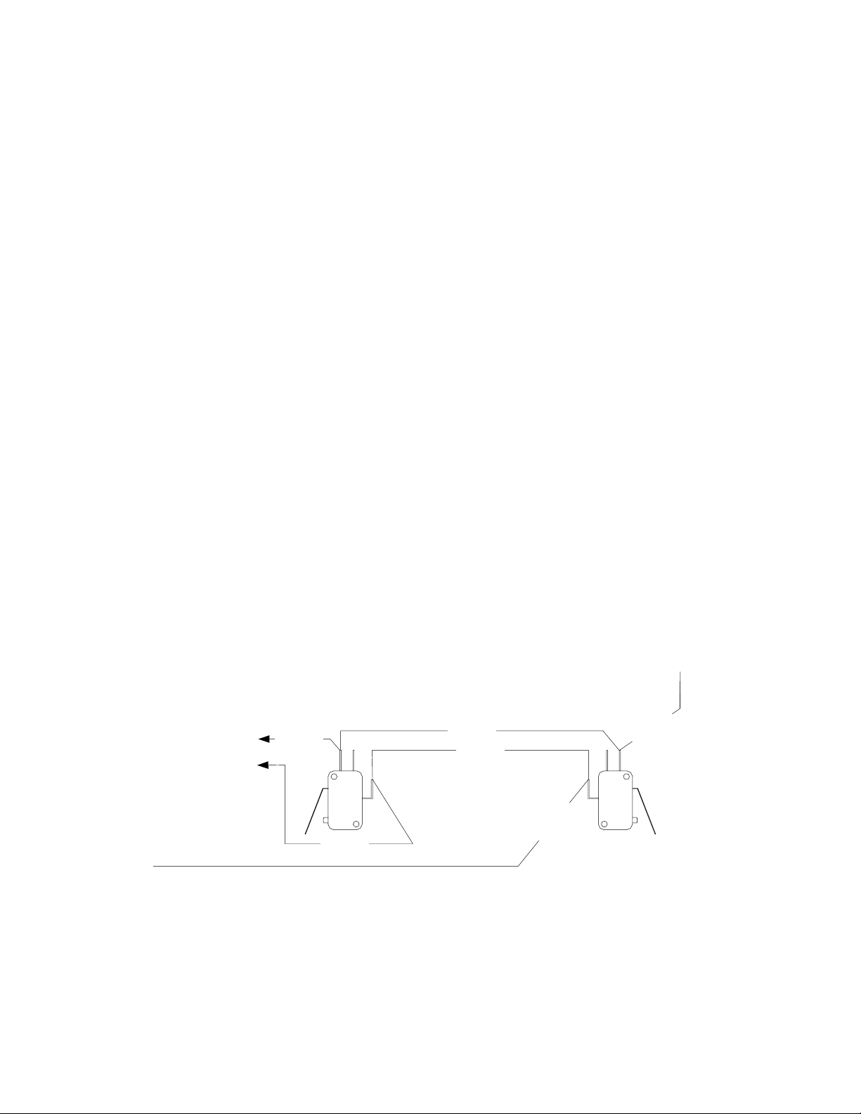
22. Reconnect the drain safety switch wiring to the switch(es) in accordance with the diagram below
then reinstall the switch covers.
Left Dual-Vat
TO SWITCHES ON
ADJACENT FRYER
Oil Return Switch
71C RED
71C RED
70C RED
D
RE
C
7
1
D
E
R
C
6
70C RED
2
Right Dual-Vat or Full-Vat
Oil Return Switch
23. Reinstall the drain tube assembly.
24. Reinstall the tilt housing and back panels, top cap, and top connecting strip.
25. Reinstall controllers in the control panel frame and reconnect the wiring harnesses and ground
wires.
26. Reposition the fryer under the exhaust hood and reconnect it to the electrical power supply.
1-8
Page 13
1.8 Built-in Filtration System Service Procedures
1.8.1 Filtration System Problem Resolution
One of the most common causes of filtration problems is placing the filter paper on the bottom of the
filter pan rather than over the filter screen.
CAUTION
Ensure that filter screen is in place prior to filter paper placement and filter pump
operation. Improper screen placement is the primary cause of filtration system
malfunction.
Whenever the complaint is “the pump is running, but no oil is being filtered,” check the installation
of the filter paper, and ensure that the correct size is being used. While you are checking the filter
paper, verify that the O-ring on the bottom of the filter pan is present and in good condition. A
missing or worn O-ring allows the pump to take in air and decreases its efficiency. Also, oil leaks
on the floor each time a vat is drained.
If the pump motor overheats, the thermal overload will trip and the motor will not start until it is
reset. If the pump motor does not start, press the red reset switch (button) located on the rear of the
motor.
If the pump starts after resetting the thermal overload switch, then something is causing the motor to
overheat. A major cause of overheating is when several frypots are filtered sequentially, thus
overheating the pump and motor. Allow the pump motor to cool at least 30 minutes before resuming
operation. Pump overheating can be caused by:
• Solidified shortening in the pan or filter
Sediment Particle
lines, or
• Attempting to filter unheated oil or
shortening (cold oil and shortening are
Oil Flow
more viscous, overloading the pump
motor and causing it to overheat).
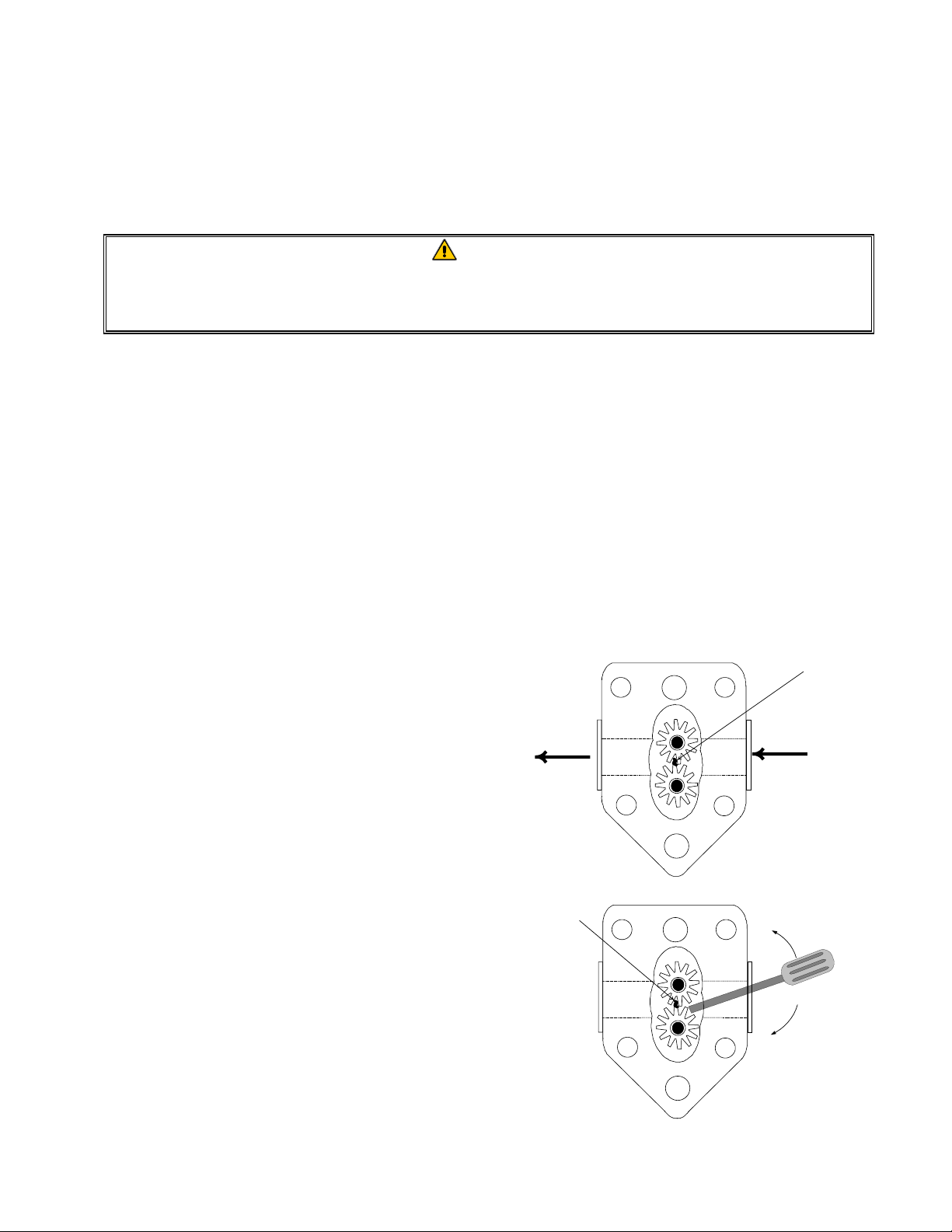
If the motor runs but the pump does not, there is
a blockage in the pump. Incorrectly sized or
installed paper/pads will allow food particles
and sediment to pass through the filter pan and
into the pump. When sediment enters the pump,
Sediment Particle
Up for reverse
the gears bind, causing the motor to overload,
again tripping the thermal overload. Shortening
that has solidified in the pump will also cause it
to seize, with the same result.
Down for forward
A pump seized by debris or hard shortening can
usually be freed by manually moving the gears
with a screwdriver or other instrument.
1-9
Page 14
Disconnect power to the filter system, remove the input plumbing from the pump, and use a
screwdriver to manually turn the gears.
● Turning the pump gears in reverse will release a hard particle.
● Turning the pump gears forward will push softer objects and solid shortening through the
pump and allow free movement of the gears.
Incorrectly sized or installed paper/pads will also allow food particles and sediment to pass through
and clog the suction tube on the bottom of the filter pan. Particles large enough to block the suction
tube may indicate that the crumb tray is not being used. Pan blockage can also occur if shortening is
left in the pan and allowed to solidify. Blockage removal can be accomplished by forcing the item
out with an auger or drain snake. Compressed air or other pressurized gases should not be used to
force out the blockage.
1.8.2 Replacing the Filter Motor, Filter Pump, and Related Components
1. Remove the filter pan and lid from the unit. Drain the frypots into an oil disposal unit (MSDU)
or other appropriate metal container.
DANGER
DO NOT drain more than one full frypot or two split frypots into the MSDU at one time.
2. Disconnect the fryer from the electrical power supply and reposition it to gain access to both the
front and rear.
3. Remove the two lower back panels, unplug the wiring harnesses from the contactor boxes, and
remove the two screws that secure one of the boxes in place (it doesn’t matter which one; see
illustration on page 1-6). NOTE: If you remove the screws from both boxes at the same time,
the boxes will jam against each other and neither can be removed.
4. Carefully lower the box to the floor and pull it out the front of the fryer. Remove the remaining
box following the same procedure.
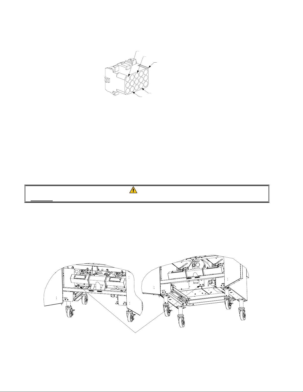
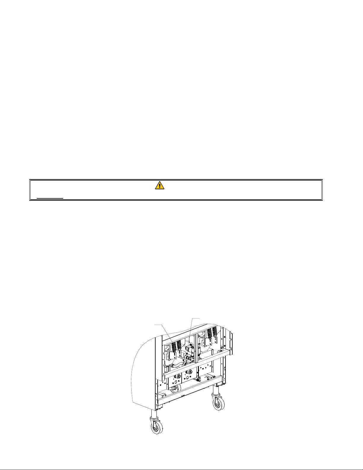
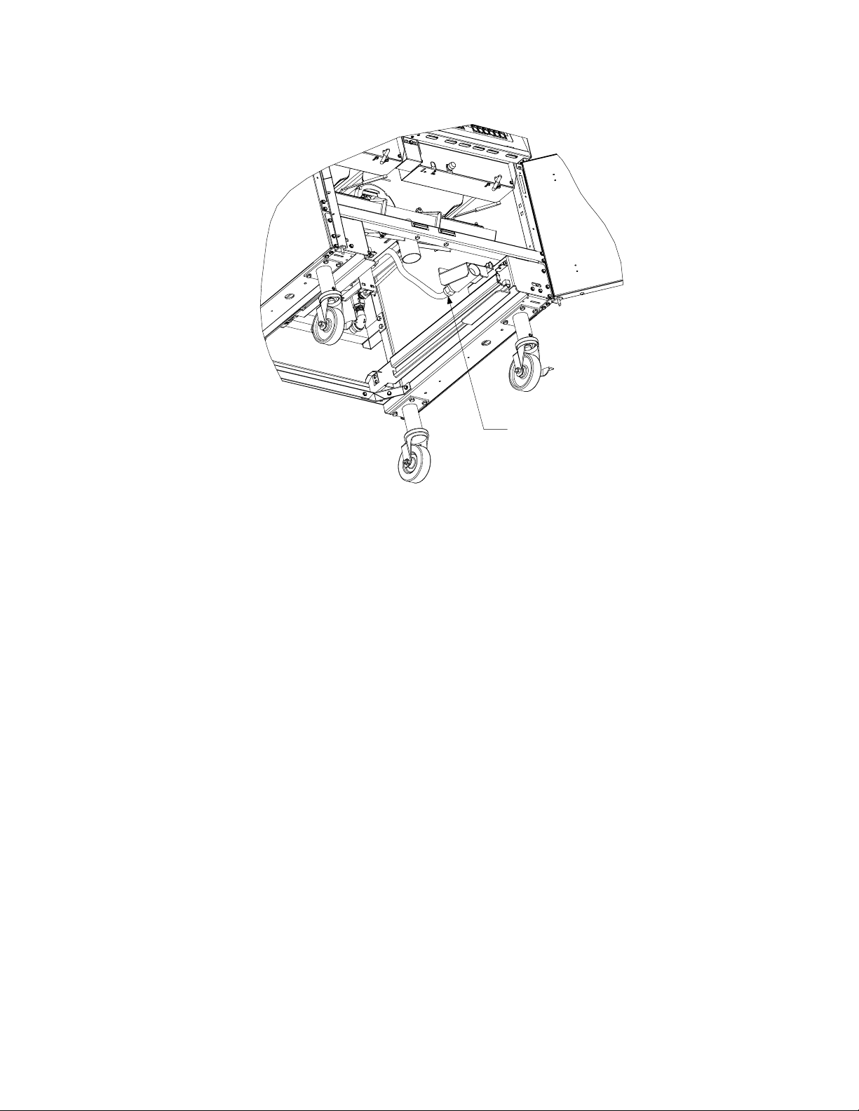
5. Disconnect the two flexlines running to the oil-return manifold at the rear of the fryer. Remove
the nut and bolt that secures the bridge to the oil-return manifold.
Disconnect vacuum-breaker
Disconnect pump
solenoid flexline here.
solenoid flexline here.
1-10
Page 15
6. Disconnect the pump suction flexline at the filter pan connection end.
Disconnect pump suction
flexline here.
7. Remove the cover plate from the front of the motor and disconnect the motor wires.
8. Unplug the 15-pin connector from the rear of the left component box and, using a pin pusher,
disconnect the solenoid valve wires (pins 4, 6, 10 and 12). NOTE: If the vacuum-breaker
solenoid valve is connected to the manifold rather than the pump, its wires (pins 4 and 6) do not
need to be disconnected.
9. Remove the two nuts and bolts that secure the front of the bridge to the cross brace and carefully
slide the bridge rearward off the cross brace until its front end can be lowered to the floor. Be
careful not to let the rear of the bridge slip off the manifold at this point. NOTE: In some early
production units, the bridge will not slide far enough to the rear to clear the front brace. In such
cases, the front brace must be removed. It is held in place by two hex head screws on each end
and a nut and bolt inside the brace near each end.
10. Get a good grip on the bridge, carefully pull it forward off the oil-return manifold, and lower the
entire assembly to the floor. Once on the floor, pull the assembly out the front of the fryer.
11. When required service has been completed, reverse steps 6-12 to reinstall the bridge. NOTE:
The black motor wires go on the top terminal, the white on the bottom. The pump solenoid valve
wires go in positions 10 and 12 of the 15-pin connector; the vacuum-breaker solenoid valve
wires go in positions 4 and 6. In both cases, polarity does not matter.
12. Once the bridge is back in place, reverse steps 4 and 5 to reinstall the contactor boxes.
13. Reconnect the unit to the electrical power supply, and verify that the pump is functioning
correctly (i.e., when a filter handle is placed in the ON position, the motor should start and there
should be strong suction at the intake fitting and outflow at the power shower or rear flush port).
1-11
Page 16
14. When proper operation has been verified, reinstall the back panels and the filter pan and lid, and
return the fryer to service.
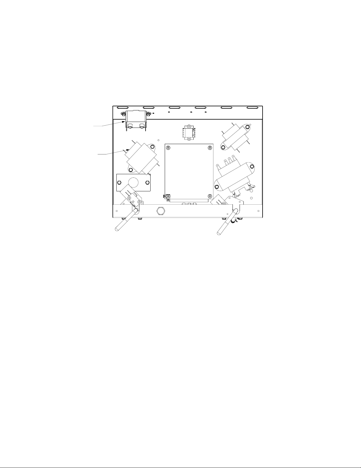
1.8.3 Replacing the Filter Transformer or Filter Relay
Remove the left controller from the fryer to expose the interior of the left component box. The filter
transformer and relay are located as shown in the illustration below. NOTE: The right component
box is identical to the left except that the filter transformer and relay are not present.
Filter
Relay
Filter
Transformer
Dual-vat configuration illustrated. In full-vat units, left filter handle is not present.
1-12
Page 17
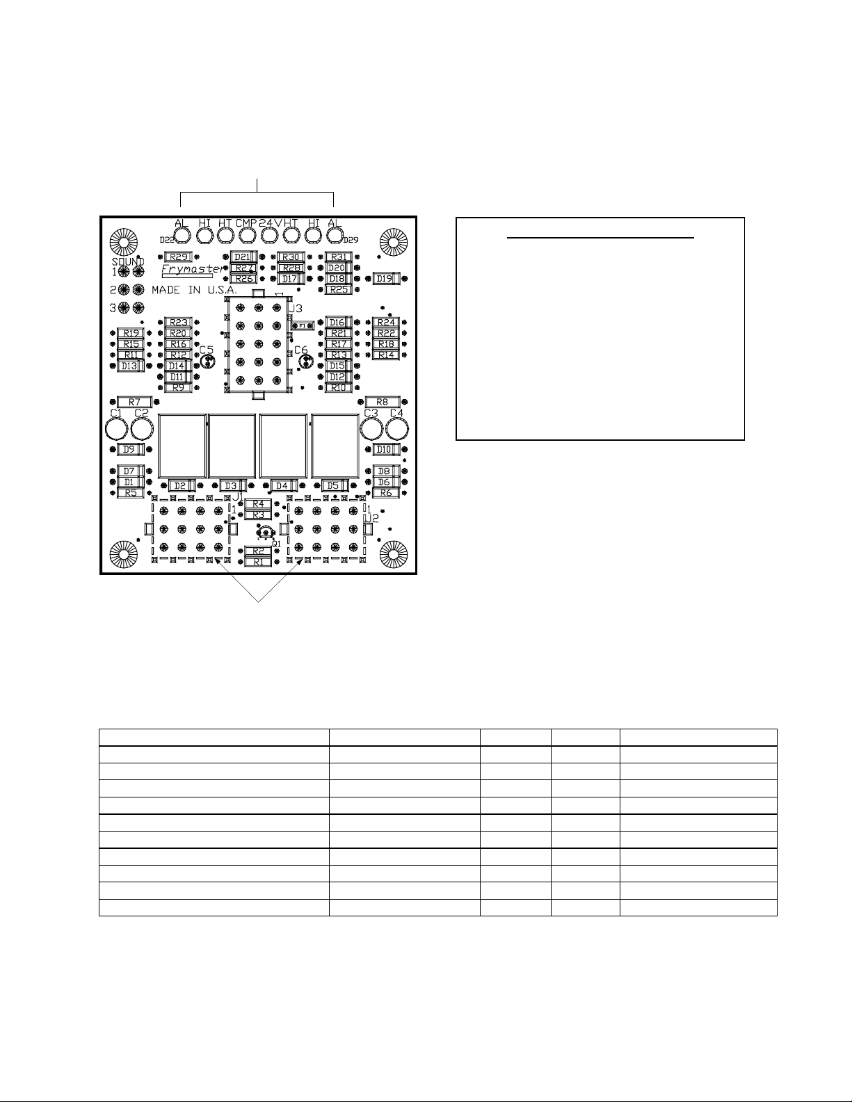
1.9 Interface Board Diagnostic Chart
The following diagram and charts provide ten quick system checks that can be performed using only
a multimeter.
Diagostic LEDs
Diagnostic LED Legend
CMP indicates power from 12V transformer
24 indicates power from 24V transformer
HI (RH) indicates output (closed) from right latch
relay
HI (LH) indicates output (closed) from left latch
relay
HT (RH) indicates output from right heat relay
HT (LH) indicates output from left heat relay
AL (RH) indicates output (open) from right latch
relay
AL (LH) indicates output (open) from left latch
relay
K1
Latch
Left
Relay
K2
Left
Heat
Relay
23
6
5
8
9
12
11
15
14
K3 K4
Relay
1
4
7
10
13
Right
Heat
Right
Latch
Relay
4
1
7
10
5
2
8
11
6
3
9
12
4
1
7
10
5
2
8
11
6
3
9
12
Test Points
J1 Left J2 Right
Meter Setting Test Pin Pin Results
12 VAC Power 50 VAC Scale 1 of J2 3 of J2 12-16 VAC
24 VAC Power 50 VAC Scale 2 of J2 Chassis 24-30 VAC
*Probe Resistance (RH) R X 1000 OHMS 11 of J2 12 of J2 See Chart
*Probe Resistance (LH) R X 1000 OHMS 3 of J1 2 of J1 See Chart
Hi-Limit Continuity (RH) R X 1 OHMS 7 of J2 4 of J2 0 - OHMS
Hi-Limit Continuity (LH) R X 1 OHMS 4 of J1 7 of J1 0 - OHMS
Latch Contactor Coil (RH) R X 1 OHMS 8 of J2 Chassis 3-10 OHMS
Latch Contactor Coil (LH) R X 1 OHMS 5 of J1 Chassis 3-10 OHMS
Heat Contactor Coil (RH) R X 1 OHMS 9 of J2 Chassis 18-25 OHMS
Heat Contactor Coil (LH) R X 1 OHMS 6 of J1 Chassis 18-25 OHMS
* Disconnect 15-Pin harness from the computer/controller before testing the probe circuit.
1-13
Page 18

1.10 Wiring Diagrams
COMPONENT WIRING
1-14
Page 19

CONTACTOR BOX – DELTA CONFIGURATION
1-15
Page 20

CONTACTOR BOX – WYE CONFIGURATION
1-16
Page 21

BIPH14/MPH14 SERIES ELECTRIC FRYERS
2.1 Accessories
CHAPTER 2: PARTS LIST
1
2
6
3
4
5
7
10
8
9
11
STANDARD
ITEM
PART #
1 809-0171 Thumbscrew, ¼ -20 X 1
EURO-LOOK
PART #
COMPONENT
3
/
-inch
8
2 810-1403 Hanger, Wireform Basket
* 809-0921 Spacer, Basket Hanger
3 803-0197 Cleanout Rod, 27-inch
4 803-0209 Brush, Frypot
5 823-1885 Connecting Strip, Frypot
6 806-3068 Cover, Full-Vat Frypot
* 806-3071 Cover, Dual-Vat Frypot
7 803-0099 Basket, Full-Vat
8 803-0271 Basket, Dual-Vat (Twin)
9 803-0122 Sediment Tray, Left Dual-Vat
* 803-0123 Sediment Tray, Right Dual-Vat
* 803-0113 Sediment Tray, Full-Vat
10 803-0132 Rack, Full-Vat Basket Support
11 803-0106 Rack, Dual-Vat Basket Support
* 803-0002 Powder, Filter (80 1-Cup Applications)
* 803-0046 Cup, Plastic Measuring
* 803-0170 Pack, 100-Sheet Filter Paper
* Not illustrated. Use standard part.
2-1
Page 22

2.2 Cabinetry
2.2.1 Back Panels, Control Panel Frames, Doors, Sides, Tilt Housings, and Top Caps
1
2
3
8
7
9
4
5
13
1211
6
10
2-2
Page 23

ITEM
STANDARD
PART #
EURO-LOOK
PART # COMPONENT
1 Back Panel, Upper (Panel for five station fryer shown)
200-2299 200-6630 Two Station Fryer
200-2380 200-6785 Three Station Fryer
200-3490 200-6786 Four Station Fryer
200-3670 200-6787 Five Station Fryer
2 Back Panel, Center (Panel for five station fryer shown)
200-2298 Two Station Fryer
200-2379 Three Station Fryer
200-3489 Four Station Fryer
200-3669 Five Station Fryer
3 Back Panel, Lower (Panel for five station fryer shown)
200-4430 200-4426 Two Station Fryer
200-4431 200-4427 Three Station Fryer
200-4432 200-4428 Four Station Fryer
200-4433 200-4429 Five Station Fryer
4 Frame, Control Panel (Frame for five station fryer shown)
806-7172SP 106-4378 Two Station Fryer (use 106-5221SP for fryers mfd. After 6.22.05)
806-7173SP 106-4391 Three Station Fryer (use 106-5018SP for fryers mfd. After 6.22.05)
806-7174SP 106-4392 Four Station Fryer (use 106-5019 for fryers mfd. After 6.22.05)
806-9776SP 106-4393 Five Station Fryer (use 106-5020 for fryers mfd. After 6.22.05)
5 210-4435 Side, Standard Cabinet Left or Right
6 810-2346 Magnet, Door
7 Tilt Housing (Housing for five station fryer shown)
824-1061 824-1303 Two Station, S/S
824-1057 824-1327 Two Station, Aluminized Steel
824-1062 824-1335 Three Station, S/S
824-1058 824-1338 Three Station, Aluminized Steel
824-1063 824-1336 Four Station, S/S
824-1059 824-1339 Four Station, Aluminized Steel
824-1064 824-1337 Five Station, S/S
824-1060 824-1340 Five Station, Aluminized Steel
8 826-1351 809-0015 Nut Retainer, ¼-20 (Pkg. of 10 – receives basket hanger thumbscrew)
9 Top Cap (Top cap for five station fryer shown) (Also requires 809-
0078 Nutserts)
824-0869 106-4436 Two Station (use 106-5196 for fryers mfd. After 6.22.05)
824-0870 106-4438 Three Station (use 106-5197 for fryers mfd. After 6.22.05)
824-0871 106-4440 Four Station (use 106-5198 for fryers mfd. After 6.22.05)
824-0872 106-4442 Five Station (use 106-5199 for fryers mfd. After 6.22.05)
Cap-N-Splash
* 823-3074 Two Station
* 823-3075 Three Station
* 823-3077 Four Station
* 823-3076 Five Station
10 806-6545SP 106-4397 Door, Left or Right (Left shown – move handle to bottom for right)
11 809-0266 Screw, #10 X ½-inch Phillips Truss Head
12 810-1422 210-6816 Handle, Wireform Door
13 106-0554 Pin Assembly, Door
* 810-0275 Spring, Door Pin
* 824-0532 Housing, MAC114 HE Tilt with cap/splash
* 824-0534 Housing, MAC214 HE Tilt with cap/splash
* 824-0535 Housing, MAC314 HE Tilt with cap/splash
* 824-0536 Housing, MAC414 HE Tilt with cap/splash
* Not illustrated. Use standard part.
2-3
Page 24

2.2.2 Cabinet Bases, Braces, and Associated Parts
See Page 2-2 for cabinet sides.
See Page 2-30 for rear bridge
2
support/oil return manifold.
1
20
2414
2415
4
282218
17
3
8 25
21 23
7
16
2410
9 24
2412
2410
26
11 24
6
5
17
See Page 2-26 for filter rails
and associated hardware.
27 28 33
27 28 32
30
31
29
19
The 5-Station cabinet illustrated is typi cal of all
BIPH14/MPH14 cabinets. All components used
in BIPH14/MPH14 cabinets are identified, but not
all components are used in every configuration.
2-4
Page 25

ITEM
STANDARD
PART #
EURO-LOOK
PART # COMPONENT
1 106-1265SP Upright Assembly, Left
2 106-1266SP Upright Assembly, Right
3 200-1651 Support, Cross Cabinet
4 200-1659 Divider, Cabinet
5 200-2293 Brace, Single Station Lower
6 200-3774 Brace, Double Station Lower
7 Brace, Front Horizontal
200-2331 Two-Station Fryer
200-2296 Three-Station Fryer
200-2733 Four-Station Fryer
200-3590 Five-Station Fryer
8 Brace, Rear Horizontal
200-2284 Two-Station Fryer
200-2295 Three-Station Fryer
200-2725 Four-Station Fryer
200-3592 Five-Station Fryer
9 200-4422 Support, Contactor Box Right Station 3 or Station 5
10 201-4425 Support, Contactor Box Left Station 4 or Station 5
11 202-4425 Support, Contactor Box Right Station 3
12 200-4423 Support, Contactor Box Stations 3 and 4
13 200-4447 Support, Contactor Box Front to Rear
14 201-5369 Support, Contactor Box Station 2
15 202-5369 Support, Contactor Box Station 1
16 200-4424 Post, Door
17 810-2346 Magnet, Door
18 200-4786 Support, Oil Return Manifold
19 210-5595 Hinge, Door
20 210-1490 Bracket, Rear Support
21 900-1224 Bracket, Frypot
22 809-0131 Bolt, ¼-20 X ¾-inch Hex Head (also used w/Item 27 to mount filter rails)
23 826-1371 Screw, #8 X ½-inch Drill Point Hex Head (Pkg. of 25)
24 826-1330 Screw, 10-32 X ⅜-inch Slotted (Pkg. of 25, used to attach contactor box)
25 809-0256 Nut, 10-32 Keps Hex
26 809-0412 Screw, #10 X ½-inch Hex Washer Head (primary cabinet screw)
27 809-0417 Nut, ¼-20 Hex Flange
28 809-0429 Bolt, ¼-20 X 2-inch Hex Head
29 200-5417 Brace, Rear Channel Corner
30 Channel, Base Rear
200-5463 Two-Station Fryer
200-5538 Three-Station Fryer
200-5537 Four-Station Fryer
200-5536 Five-Station Fryer
31 824-1131 Channel, Base Side
32 810-0326 Caster with Brake
33 810-0327 Caster without Brake
Use standard part.
2-5
Page 26

2.3 Drain System Components
2.3.1 Drain Tube Sections and Associated Parts
See Page 2-10 for Drain Valves
5
6
7
8
12
14
1
2
11
3
4
17
1618
13
6
7
10
19
5
1
2
3
4
9
15
2-6
Page 27

STANDARD
ITEM
PART # **
COMPONENT
1 813-0284 Nipple, ¾ X 1-inch NPT
2 816-0092 Grommet, 1-inch Drain
3 826-1345 Washer, 1-inch Drain (Pkg. of 25)
4 809-0347 Nut, 1-inch NPT Retainer
5 809-0893 Nut, 8-32 High Crown Acorn
6 826-1348 Cover, Drain Cleanout (Pkg. of 5)
7 816-0021 Gasket, Drain Cleanout
8 Drain Tube, Left End Short
823-3380 Full-Vat
823-3379 Dual-Vat
9 Drain Tube, Right End Short
823-1549 Full-Vat
823-1551 Dual-Vat
10 Drain Outlet
823-3229 With Vacuum Breaker Vent
823-2336 Without Vacuum Breaker Vent
11 810-2492 Fitting, Quick-Connect Straight (receives Teflon vent tube)
12 Drain Tube, Left End Short Vented
823-2637 Full-Vat
823-2636 Dual-Vat
13 Drain Tube, Right End Long
823-1508 Full-Vat
823-1543 Dual-Vat
14 Drain Tube, Open End Short
823-0718 Full-Vat
823-0725 Dual-Vat
15 Drain Tube, Open End Long
823-0717 Full-Vat
823-0724 Dual-Vat
16 810-0396 Clamp, Square Drain
17 809-0401 Screw, 10-32 X ¾-inch Hex Head
18 809-0256 Nut, 10-32 Keps Hex
19 816-0032 Gasket, Square Drain
* 826-0877 Kit, Square Drain Clamp (2 each of Items 16-18 and 1 of Item 19)
* 811-1071 Tube, Teflon Vent
* Not illustrated.
** See page 2-9 for an Euro-Look parts list.
2-7
Page 28

2.3.2 Euro-Look Drain Tube and Associated Parts
1
7
6
2
2
5
8
3
3
See Page 2-12 for Drain Valves
7
6
1
2-8
4
4
Page 29

EURO-LOOK
ITEM
PART# **
COMPONENT
1 Drain Tube, Left/Right End Short
823-4625 Full-Vat
823-4624 Dual-Vat
2 Drain Tube, Left/Right Open Short
823-4643 Full-Vat
823-4642 Dual-Vat
3 Drain Tube, Right End Long
823-4639 Full-Vat
823-4638 Dual-Vat
4 Drain Tube, Left/Right Open Long
823-4641 Full-Vat
823-4640 Dual-Vat
5 823-4892 Drain Outlet
6 816-0625 Sleeve
7 809-0969 Clamp
8 810-2492 Fitting, Quick-Connect Straight (receives Teflon vent tube)
* KIT6033 Kit, Round Drain Clamp (2 or Item 7 and 1 of Item 6)
* 811-1071 Tube, Teflon Vent
* Not illustrated.
** See page 2-7 for a standard parts list.
2-9
Page 30

2.3.3 Drain Valves and Associated Parts (Units with Built-In Filtration)
2-10
Page 31

STANDARD
ITEM
PART # **
COMPONENT
1 809-0539 Nut, ⅜-16 2-Way Hex Lock
2 900-2934 Retainer, Dual-Vat Drain Valve Nut
3 823-4133 Handle, Dual-Vat Drain Valve
4 810-0677 Grip, Drain Handle
5 809-0237 Nut, 4-40 Keps Hex
6 901-2348 Cover, Dual Vat Drain Safety Switch
7 807-2103 Microswitch, CE Straight Lever
8 816-0220 Insulation, Drain Safety Switch
9 810-1165 Washer, Teflon Drain Valve
10 809-0196 Washer, ⅜-inch Flat
11 106-2671SP Bracket Assembly, Dual-Vat Drain Safety Switch
12 810-1338 Valve, 1-inch Dual-Vat Drain
13 809-0540 Nut, ½-13 2-Way Hex Lock
14 824-1602 Handle, Full-Vat Drain Valve
15 816-0639 Cap, Red Handle
16 806-8137SP Bracket Assembly, Full-Vat Drain Safety Switch
17 810-1020 Valve, 1.25-inch Full-Vat Drain
* WIR0572 Wire Bundle, Drain Safety Switch
* Not illustrated.
** See page 2-13 for an Euro-Look parts list.
2-11
Page 32

2.3.4 Euro-Look Drain Valves and Associated Parts (Units with Built-In Filtration)
4
1
2
3
Dual-Vat Drain Valve
Assembly 106-3761
Compression Washers
10
18
9
Flat Washer
Plastic Washer
20
15
5
6
7
8
11
12
13
19
14
Full-Vat Drain Valve
Assembly 106-3760
Compression Washers
6
5
7
8
9
16
18
17
20
2-12
Page 33

EURO-LOOK
ITEM
PART # **
COMPONENT
1 809-0539 Nut, ⅜-16 2-Way Hex Lock
2 900-2934 Retainer, Dual-Vat Drain Valve Nut
3 823-4133 Handle, Dual-Vat Drain Valve
4 810-0677 Grip, Drain Handle
5 809-0237 Nut, 4-40 Keps Hex
6 901-2348 Cover, Dual Vat Drain Safety Switch
7 807-2103 Microswitch, CE Straight Lever
8 816-0220 Insulation, Drain Safety Switch
9 810-1165 Washer, Teflon Drain Valve
10 809-0196 Washer, ⅜-inch Flat
11 106-2671 Bracket Assembly, Dual-Vat Drain Safety Switch
12 810-1114 Valve, 1-inch Dual-Vat Drain
13 809-0540 Nut, ½-13 2-Way Hex Lock
14 824-1602 Handle, Full-Vat Drain Valve
15 816-0639 Sleeve, Red Handle
16 806-8137 Bracket Assembly, Full-Vat Drain Safety Switch
17 810-1018 Valve, 1.25-inch Full-Vat Drain
18 200-6496 Support, 3” Drain
19 900-2936 Retainer, Full-Vat Drain Valve Nut
20 816-0135 Round Drain O-Ring
* WIR0572 Wire Bundle, Drain Safety Switch
*Not illustrated.
** See page 2-11 for a standard parts list.
2.3.5 Drain Valves and Associated Parts (Units without Built-In Filtration)
1
4
5
2
3
ITEM
STANDARD
PART #
EURO-LOOK
PART #
COMPONENT
1 810-1569 Valve, 1.25-inch Non-Filter Full-Vat Drain
2 806-7915SP Valve, 1-inch Non-Filter Dual-Vat Left Drain
3 806-7916SP Valve, 1-inch Non-Filter Dual-Vat Right Drain
4 812-1226 Drain Extension, 1.25-inch
5 812-1227 Drain Extension, 1-inch
Use standard part.
2-13
Page 34

2.4 Electronics and Wiring Components
2.4.1 Component Boxes
169
1911
6
1
3 15 18
194
191113 19
10 19
3 15 18
8 10 191948 8 19194
5
192
6
5
21
87 16 17 20
24
19
1
21
22
120V and 480V Boxes 208-240V NON-CE Boxes
192192
23
6
8 12 19
3 15 18
208-240V CE Boxes
9 19
1
5
21
87 16 17 20 87 16 17 20
NOTE 1: The transformer on the left side of the
component box is present only in units with built-in
filtration and then only in the left component box.
NOTE 2: See Page 2-25 for Component Box 15-Pin
Wiring Harnesses.
2-14
Page 35

ITEM
STANDARD
PART #
EURO-LOOK
PART #
COMPONENT
1 106-1531SP Box Assembly, Component
2 200-3300 Bracket, Component Box Strain Relief
3 806-9495SP Terminal Block and Wire Assembly
4 807-0012 Relay, 18 Amp ⅓ HP 24V Coil
5 807-0037 Terminal, ¼-inch Push-on
6 807-0121 Bushing, Heyco Plastic AB-625-500
7 807-1321 Holder, AGC Panel-Mount ¼-inch Fuse
8 807-1597 Fuse, 3 Amp Slow-Blow
9 807-2180 Transformer, 208-240V 50VA
10 807-2181 Transformer, 100-120V/24V 60VA
11 807-0680 Transformer, 208-240V/24V 20VA
12 807-2191 Transformer, 208-240V/12V 30VA
13 807-0855 Transformer, 100-120V/12V 20VA
14 807-0979 Transformer, 208-240V/12V 43VA
15 826-1366 Nut, 4-40 Keps Hex (Pkg. of 25)
16 809-0250 Nut, 6-32 Keps Hex
17 809-0349 Spacer, 4mm X 6mm Aluminum
18 826-1359 Screw, 4-40 X ¾-inch Slotted Round Head (Pkg. of 25)
19 809-0359 Screw, #8 X ¼-inch Hex Washer Head
20 Interface Board
806-6336SP Standard (Non-Triac), Full- or Dual-Vat
806-6347SP Triac, Full- or Dual-Vat
21 807-3932 Relay, Heat/Latch 12VDC SPDT 12A
22 200-3844 Guard, Finger
23 810-2445 Plug Button
24 200-3243 Brace, Component Box
* 807-3520 Speaker, 4-Watt
* Not illustrated. Use standard part.
2-15
Page 36

2.4.2 Contactor Boxes
12 30
262213
299
241110
4 30
3 30
8 24 27
15 16 31
5 7 22 26
1
2
31
OR
6 30
CONVENTIONAL CONFIGURATION
WYE configurations
also have Item 19,
mounted with Items 25
and 28, here.
304
303
27248
17 23
OR
18 23
1
5
TRIAC CONFIGURATION
NOTE: See Pages 2-21 and 2-22 for Contactor Box Wiring Harnesses
2-16
311615
2
3126227
OR
306
Page 37

NOTES: Left and right contactor box assemblies are mirror images of one another. With the
exception of the box itself, all components of a left-hand assembly are the same as those in the
corresponding right-hand assembly and vice versa. The configurations illustrated show all possible
components, but a particular configuration may not have all the components shown.
ITEM
STANDARD
PART #
EURO-LOOK
PART # COMPONENT
1 106-1536SP Box Assembly, Left Contactor
2 106-1537SP Box Assembly, Right Contactor
3 200-3111 Cover, Cord Cutout
4 900-2752 Plate, Cordset Adapter
5 200-2334 Door, Contactor Box Hinged
6 200-4712 Door, Contactor Box
7 810-0519 Hinge, Contactor Box Door
8 807-0070 Terminal, Ground Lug
9 200-2336 Bracket, Contactor Box Fuse Block
10 807-0501 Fuse Block, 3-Pole
11 807-2240 Fuse, 60 Amp 300VAC
12 200-2337 Bracket, Mercury Contactor
13 807-1071 Contactor, 24V 30 Amp Mercury
14 807-0884 Contactor, 24V 35-50 Amp Mercury
15 810-1202 Contactor, 24V 40 Amp 3-Pole
16 809-0448 Clip, Tinnerman
17** 806-8674 Heatsink Assembly, DV Solid State Relay (See components below)
18** 806-8673 Heatsink Assembly, FV Solid State Relay (See components below)
19 806-9124 Filter Assembly, Triac (used in Wye-configured Triac units only)
20 826-1358 Nut, 6-32 Keps Hex (Pkg. of 25)
21 826-1365 Screw, 6-32 X ⅜-inch Slot Head (Pkg. of 25)
22 809-0104 Screw, 8-32 X ½-inch Slot Head
23 826-1330 Screw. 10-32 X ⅜-inch Slot Head (Pkg. of 25)
24 809-0123 Screw, #10 X ¾-inch Slot Head
25 826-1366 Nut, 4-40 Keps Hex (Pkg. of 25)
26 809-0247 Nut, 8-32 Keps Hex
27 826-1376 Nut, 10-32 Keps Hex (Pkg. of 10)
28 826-1359 Screw, 4-40 X ¾-inch Slot Head (Pkg. of 25)
29 809-0359 Screw, #8 X ¼-inch Hex Washer Slot Head
30 809-0360 Screw, #8 X ⅜-inch Hex Washer Slot Head
31 826-1374 Screw, #10 X ½-inch Hex Head (Pkg. of 25)
* 200-5627 Lid, Left or Right Contactor Box
* Components of Items 17 and 18
** 807-2751 Relay, Solid State 50 Amp 280V
* 826-1562 Heatsink, Solid State
* 807-0037 Terminal, ¼-inch Push-on
* 809-0096 Screw, 6-32 X ⅝-inch Slot Head
Use standard part.* Not illustrated.
** Dual-vat assembly has six relays (826-1562); full-vat assembly has three relays.
2-17
Page 38

2.4.3 Heating Element Assemblies and Associated Parts
FULL-VAT ELEMENT ASSEMBLY
3
4
9
7
6
8
18
5
11
10
DUAL-VAT ELEMENT ASSEMBLY
17
1
2
1312
15
1
1413
16
20
NOTES:
The dual-vat assem bly is the sam e as the f ull-vat asse mbly except for havin g two of Item s 2, four of Item 17 ins tead of
two of Item 16, and t wo of Item 10 ins tead of one of I tem 10 and one of Item 11. The only diff erence between elem ent
assemblies for different voltage and k W ratings is t h e el ement itself (I tem 1)
Items 19 and 20 are s hown as as sociated parts. They are no t part of ei t h er el ement assembly.
19
2-18
Page 39

ITEM
STANDARD
PART #
EURO-LOOK
PART #
COMPONENT
1 Element
826-2151 200V 17.0 kW
826-2149 208V 17.0 kW
826-2155 220V 17.0 kW
826-2152 230V 17.0 kW
826-2153 230V/400V 7.0/8.5 kW (used in export 3-phase 4-wire wye units)
826-2154 240V 17.0 kW
826-2161 480V 17.0 kW
2 826-1526 Probe, Temperature
3 106-0004SP Tilt Plate Assembly
4 106-0572SP Bracket, Left Spring Slot
5 106-0573SP Bracket, Right Spring Slot
6 910-9641 Tilt Plate
7 810-0035 Hinge
8 826-1330 Screw, 10-32 X ⅜-inch Slotted Truss Head (Pkg. of 25)
9 826-1376 Nut, 10-32 Keps Hex (Pkg. of 10)
10 826-1339 Bushing, .375-inch Split (Pkg. of 10)
11 816-0480 Plug, .375-inch Dome
12 910-5022 Bracket, Temperature Probe
13 809-0518 Screw, 8-32 X ⅜-inch Slotted Hex Head
14 910-2042 Clamp, Element (Short)
15 910-5213 Clamp, Element (Long)
16 910-3681 Support, Full-Vat Element Rear
17 910-5214 Support, Dual-Vat Element Rear
18 809-0567 Tie-Wrap, Metal
19 200-2060 Bracket, Lower Spring Slot
20 810-0297 Spring, Element
* 826-1061 Tilt Switch, Mercury Non-CE (Full-Vat requires one switch
and Dual-Vat requires two.)
* 826-2228 Tilt Switch (CE fryers) (Full-Vat requires one switch and
Dual-Vat requires two.)
* Not illustrated. Use standard part.
2-19
Page 40

2.4.4 Computers
NOTE: See Page 2-25 for Interface Board to Computer Wiring Harness
STANDARD
ITEM
PART #
COMPONENT
Replacement Computer (without bezel), Dual- or Full-Vat
106-0529B Non-CE
106-2436B CE
823-2986 Replacement Bezel
EURO-LOOK
ITEM
PART # COMPONENT
Replacement Computer (without bezel)
106-1269 Non-CE
106-0672 CE
106-3755 Replacement Frame Assembly
2-20
Page 41

2.4.5 Wiring
2.4.5.1 Contactor Box Wiring Assemblies – 12-Pin Dual-Vat C-1
1
2
3
4
5
1
2
6
7
8
9
10
11
12
1
2
3
4
5
6
7
8
9
10
11
12
BLACK
GREEN/YELLOW
WHITE
BROWN
ORANGE
BLACK
ORANGE
WHITE
BLACK
BLACK
BLACK
GREEN/YELLOW
WHITE
BROWN
ORANGE
BLACK
ORANGE
WHITE
BLACK
YELLOW
BLACK
ITEM
STANDARD
PART #
EURO-LOOK
PART # COMPONENT
1 106-2428SP Standard
2 106-2343SP Triac
Use standard part.
2-21
Page 42

2.4.5.2 Contactor Box Wiring Assemblies – 12-Pin Full-Vat C-1
1
2
3
4
5
1
6
7
8
9
10
11
12
BLACK
GREEN/YELLOW
WHITE
BROWN
WHITE
BLACK
ORANGE
BLACK
1
2
3
4
5
2
6
7
8
9
10
11
12
BLACK
GREEN/YELLOW
WHITE
BROWN
WHITE
BLACK
ORANGE
BLACK
YELLOW
ITEM
STANDARD
PART #
EURO-LOOK
PART # COMPONENT
1 Standard
106-2474SP Other than 480V
106-2522SP 480V
2 106-2475SP Triac
Use standard part.
2.4.5.3 Contactor Box Wiring Assembly – 6-Pin (Left Element)
1
2
3
4
5
6
BLUE
BLUE
BLUE
BLACK
BLACK
BLACK
106-2426SP
2.4.5.4 Contactor Box Wiring Assembly – 9-Pin (Right Element)
1
2
3
4
5
6
7
8
9
BLUE
BLUE
BLUE
BLACK
BLACK
BLACK
106-2425SP
2-22
Page 43

2.4.5.5 Main and Multi-Fryer Wiring Harnesses
15-Pin Male Connector
807-0804
C6
1
C1
J6
4-Pin Female Connector
807-3232
12-Pin Male Connector
807-0160
J1
J4
J5
J2
15-Pin Male Connector
807-0804
6-Pin Male Connector
807-0157
12-Pin Male Connector
807-0160
12-Pin Male Connector
FRYER #3
807-0160
Male Disconnect Pin
807-1049
Female Disconnect Pin
807-0701
FRYER #4
Female Disconnect Pin
807-0701
2
Male Disconnect Pins
807-1049
12-Pin Male Connector
807-0160
FRYER #5
Item 3: 807-371 6
12-Pin Connector
Wiring for 807-3716
Item 4: 807-37 17
Item 5: 807-3718
12-Pin Connector
Wiring for 807-3717
2-23
12-Pin Connector
Wiring for 807-3718
Page 44

ITEM
STANDARD
PART #
EURO-LOOK
PART #
COMPONENT
1 807-3769 Main
2 807-3715 Two-Fryer Battery
3 807-3716 Three-Fryer Battery
4 807-3717 Four-Fryer Battery
5 807-3718 Five-Fryer Battery
NOTE: Harnesses for 3-, 4-, and 5-Fryer Batteries are similar to 807-
3715 but have extra sets of leads as appropriate for the number of fryers
in the battery. The connections to Fryer #1 J2 and J4 are the same for all.
2.4.5.6 Component Box Wiring Harnesses – 15-Pin
Use standard part.
1
2 3
4
ITEM
STANDARD
PART #
EURO-LOOK
PART #
COMPONENT
1 106-2506SP 208-480V (With Filter)
2 106-2507SP 208-480V (Without Filter)
3 106-2508SP 120V (With Filter)
4 106-2509SP 120V (Without Filter)
Use standard part.
2.4.5.7 Interface Board to Controller Wiring Harness – 15-Pin
806-2071SP
2-24
Page 45

2.5 Filtration System Components
NOTE: Some early production
1
units were configured thi s way.
37
38
24
29
2
3
4
19
17
25
16
30
28
12119
14
8
20
121110
18
36
35
34
25
18
22
24
23
21
8
27
26
32
33
31
7
6
15
5
13
2-25
Page 46

ITEM
STANDARD
PART #
EURO-LOOK
PART # COMPONENT
* 826-1979 Filter Pan Roller Kit (four each of Items 7 and 8)
* 826-1980 Service Filter Pan (Item 5, four of Items 7 & 8, two o-rings, two 813-0568)
* 826-1981 826-1981 Service Filter Pan Assembly (Service Filter Pan plus Items 3 and 4)
* 826-1392 O-Ring (Pkg. of 5; used with Item 5)
* 813-0568 Plug, ⅛-inch Socket Head Pipe (used with Item 5; two required)
* 811-1071 Tubing, ¼-inch OD Teflon Vent (sold by the foot)
* 106-2851SP Heater Strip Assembly, 100-120V
* 106-2852SP Heater Strip Assembly, 208-250V
1 823-4637 823-4787 Lid (for units built before Feb 04, use 823-4391)
2 810-2743 Crumb Tray
3 810-2183 Hold-Down Ring
4 200-2240 SanaGrid Filter Screen
5 106-2617SP Pan, One-Piece Filter (includes Item 2)
6 810-2012 Rail Set, Filter Pan Roller (includes one left and one right)
7 810-2198 Roller, Filter Pan and Rail
8 826-1368 809-0417 Nut, ¼-20 Hex Flange (Pkg. of 10)
9 823-4589 Bracket, Lid Support (for units built before Feb 04, use 823-3875)
10 Guide, Filter Pan Lid
200-3556 Left
200-6709 Right
11 809-0104 809-0103 Screw, 8-32 X ½-inch Slotted Truss Head
12 809-0247 Nut, 8-32 Hex Keps
13 823-3879 Suction Tube
14 200-4408 Rail, Left Filter
15 200-4409 Rail, Right Filter
16 Motor and Gasket Kit
826-1785 807-3858 100V 50/60 Hz
826-1712 807-3859 115V 50/60 Hz
826-1756 807-3860 208V 50/60 Hz
826-1757 807-3861 220-240V 50/60 Hz
826-1755 807-3862 250V 50/60 Hz
17 826-1264 Pump and Gasket Kit
810-2716 Pump, Viking 4GPM 2-piece
816-0093 Gasket, Pump/Motor
18 807-2484 Valve, ¼-inch Solenoid
19 813-0165 Elbow, ½-inch 90° Street
20 813-0342 Elbow, ½-inch 45° Street
21 813-0530 Tee, ½-inch X ¼-inch X ½-inch Reducing
22 813-0022 Nipple, ½-inch Close
23 813-0838 Nipple, ¼-inch Close
24 813-0304 Bushing, ½-inch to ¼-inch Flush
25 810-1668 Adapter, ⅝-inch to ½-inch NPT Male
26 810-1669 Adapter, ⅝-inch to ½-inch NPT Female
27 810-1680 Flexline, 6.5-inch Oil Return
28 810-1369 Flexline, 17.5-inch Oil Return
Use standard part.
Continued on next page…
2-26
Page 47

29 810-1055 Flexline, 11.5-inch Oil Return
30 807-3828 Cable, FootPrint Pro Pump Motor
31 826-1375 809-0401 Screw, 10-32 X ¾-inch Hex Trim Head (Pkg. of 5)
32 200-5950 200-8467 Bridge, Filter Motor
33 210-3149 Support, Contactor Box
34 813-0003 813-0003 Tee, ½-Inch
35 813-0298 813-0298 Nipple, ½-inch 2.0-inch
36 813-0537 813-0537 Nipple, ¼-inch 2.0-inch
37 810-2493 810-2493 Fitting, ¼-inch X 90° Quick-Connect
38 810-1160 Flexline, 3.0-inch Oil Return
* 810-1043 Flexline, 0.5-inch Oil Return
* 810-1057 Flexline, 13.0-inch Oil Return
* Not illustrated. Use standard part.
2-27
Page 48

2.6 Frypot Assemblies and Associated Parts
3
5
4
7
3
4
4
1
4
4
2
5
6
8
2-28
Page 49

STANDARD
ITEM
PART #
COMPONENT
1 823-4775 Frypot, McDonald's, Full-vat
2 823-4778SP Frypot, McDonald's, Dual-vat
3 Thermostat Assembly, High-Limit
806-7543 Non-CE Full Vat 425°F (218°C) (Color Coded Black)
806-8035 Non-CE Dual Vat 435°F (224°C) (Color Coded Red)
806-8132 CE Full and Dual Vat 415°F (213°C) (Color-Coded Yellow)
4 812-0211 Insulation, Kaowool 17-inch X 10-inch X ½-inch (4 required per pot)
5 900-4100 Retainer, Side Insulation
6 900-4101 Retainer, Front Insulation
7 900-1345 Retainer, Rear Insulation
8 826-1376 Nut, 10-32 Keps Hex (Pkg. of 10)
2-29
Page 50

2.7 Oil Return System Components
26
25
24
17
12
16
20
19
13
1514
21
18
16
22
11
21
18
17
18
13
23
19
16
12
Rear-Flush Oil Return Plumbing
Full-vat rear-flush plumbing is shown on
the left side of the oil return manifold;
dual-vat plumbing is shown on the right
20
side. Plumbing for a two-fryer battery is
Typical
illustrated, but all components except the
oil return manifold are the same
regardless o f the num ber of f ryers in th e
battery.
14 15
17
19
20
14 15
10
21
1
2
4
3
1
2-30
6
7
5
8
9
Page 51

ITEM
STANDARD
PART #
EURO-LOOK
PART #
COMPONENT
1 106-2465SP Handle Assembly, Full-Vat and Right Dual-Vat Rear Flush Complete
2 106-2687SP Handle Assembly, Left Dual-Vat Rear Flush Complete
3 807-2103 Microswitch, Straight Lever
4 106-3349 Bracket Assembly, Microswitch
5 200-5401 Bracket, Handle Retainer
6 816-0220 Insulation, Oil Return Microswitch
7 826-1366 Nut, 4-40 Keps Hex (Pkg. of 25)
8 810-2534 Rod, Full-Vat and Right Dual Vat Rear Flush (use 810-2533 for Left DV)
9 810-0677 Grip, Oil Return Valve Handle
10 809-0601 Clip, Clevis
11 810-2532 Flexline, 7.0-inch
12 810-1067 Flexline, 8.5-inch
13 810-0278 Valve, ½-inch Ball
14 200-5438 Handle, Rear Flush Valve
15 900-2935 Retainer, Oil Return Valve Nut
16 810-1668 Adapter, ⅝-inch to ½-inch NPT Male
17 810-1669 Adapter, ⅝-inch to ½-inch NPT Female
18 813-0165 Elbow, ½-inch X 90° Street
19 813-0570 Elbow, 180° ½-inch NPT
20 813-0022 Nipple, ½-inch X Close NPT
21 813-0298 Nipple, ½-inch X 2.0-inch NPT
22 813-0469 Cap, ½-inch NPT Pipe
23 810-2255 Manifold, Two-Station Fryer (use 810-2543 for non-filter units)
24 810-2256 Manifold, Three-Station Fryer (use 810-2544 for non-filter units)
25 810-2257 Manifold, Four-Station Fryer (use 810-2545 for non-filter units)
26 810-2312 Manifold, Five-Station Fryer (use 810-2546 for non-filter units)
Use standard part.
2-31
Page 52

2.8 Wiring Connectors, Pin Terminals, and Power Cords
1 2
6
STANDARD
ITEM
PART #
7 9 10
11
EURO-LOOK
PART #
Power Cords
3
8
12
4
13
5
COMPONENT
* 807-0154 100/120V–15A 3-wire, w/grounded plug
* 807-1685 100/208/240V–18A 3-wire, w/o plug
* 806-6083 120V 5-wire, w/grounded plug
* 807-3817 208/240V 3-Phase 4-wire w/grounded plug
Connectors
1 807-1068 2-Pin Female
2 807-0158 6-Pin Female
3 807-0156 9-Pin Female
5 807-0159 12-Pin Female
5 807-0875 15-Pin Female
6 807-1067 2-Pin Male
7 807-0157 6-Pin Male
8 807-0155 9-Pin Male
9 807-0160 12-Pin Male
10 807-0804 15-Pin Male
11 826-1341 Terminal, Female Split Pin (Pkg of 25)
12 826-1342 Terminal, Male Split Pin (Pkg of 25)
13 807-2518 Plug, Mate-N-Lock (Dummy Pin)
* Not illustrated. Use standard part.
2-32
Page 53

2.9 Control Cord Box
10
1
7
9
5
3
6
4
8
11
2
STANDARD
ITEM
PART #
806-9794
EURO-LOOK
PART #
COMPONENT
Control Cord Box
1 200-3379 Cover, MAC Control Cord Box
2 806-9795 Harness Assembly, MAC
3 807-0070 Terminal, Ground Lug
4 807-1683 Relay, 12 VDC Hood
5 807-1973
Terminal, Post
6 809-0104 Screw, 8-32 x ½” Truss Slotted Head
7 809-0123 Screw, #10 x ¾” Truss Slotted Head
8 809-0247 Nut,8-32 Hex Keps
9 809-0256 Nut,10-32 Hex Keps
10 809-0359 Screw, #8 x ¼” Washer Slotted Hex Head
11 900-8024 Box, MAC Control Cord
* WIR0324 Wiring Assembly
* Not illustrated.
Use standard part.
2-33
Page 54

Frymaster, L.L.C., 8700 Line Avenue, PO Box 51000, Shreveport, Louisiana 71135-1000
Shipping Address: 8700 Line Avenue, Shreveport, Louisiana 71106
TEL 1-318-865-1711 FAX (Parts) 1-318-219-7140 (Tech Support) 1-318-219-7135
PRINTED IN THE UNITED STATES
SERVICE HOTLINE
1-800-551-8633
819-6011
MAY 2006
 Loading...