

Page 1
Ultimate Electric Series Fryers
Service & Parts Manual
Frymaster Dean, a member of the Commercial Food Equipment Service Association,
recommends using CFESA Certified Technicians.
24-Hour Service Hotline 1-800-551-8633
www.frymaster.com
E-mail: service@frymaster.com
Price: $28.00
819-5981
APRIL 2011
Page 2
Please read all sections of this manual and retain for future reference.
NOTICE
This appliance is intended for professional use only and is to be operated by qualified
personnel only. A Frymaster Dean Factory Authorized Servicer (FAS) or other qualified
professional should perform installation, maintenance, and repairs. Installation, maintenance,
or repairs by unqualified personnel may void the manufacturer’s warranty. See Chapter 1 of
this manual for definitions of qualified personnel.
NOTICE
This equipment must be installed in accordance with the appropriate national and local codes of
the country and/or region in which the appliance is installed.
NOTICE TO U.S. CUSTOMERS
This equipment must be installed in accordance with the appropriate national and local codes of
the country and/or region in which the appliance is installed.
NOTICE
Drawings and photos used in this manual are intended to illustrate operational, cleaning and
technical procedures and may not conform to onsite management operational procedures.
NOTICE TO OWNERS OF UNITS EQUIPPED WITH CONTROLLERS
U.S.
This device complies with Part 15 of the FCC rules. Operation is subject to the following two
conditions: 1) This device may not cause harmful interference, and 2) This device must accept
any interference received, including interference that may cause undesired operation. While
this device is a verified Class A device, it has been shown to meet Class B limits.
CANADA
This digital apparatus does not exceed the Class A or B limits for radio noise emissions as set
out by the ICES-003 standard of the Canadian Department of Communications.
Cet appareil numerique n’emet pas de bruits radioelectriques depassany les limites de classe A
et B prescrites dans la norme NMB-003 edictee par le Ministre des Communications du Canada.
DANGER
Improper installation, adjustment, maintenance or service, and unauthorized alterations or
modifications can cause property damage, injury, or death. Read the installation, operating and
service instructions thoroughly before installing or servicing this equipment.
Page 3
DANGER
The front ledge of the fryer is not a step. Do not stand on the fryer. Serious injury can result
from slips or contact with the hot oil.
DANGER
Do not store or use gasoline or other flammable vapors and liquids in the vicinity of this or any
other appliance.
DANGER
The crumb tray in fryers equipped with a filter system must be emptied into a fireproof container
at the end of frying operations each day. Some food particles can spontaneously combust if left
soaking in certain shortening material. Additional information can be obtained in the filtration
manual included with the system.
WARNING
No structural material on the fryer should be altered or removed to accommodate placement of
the fryer under a hood. Questions? Call the Frymaster Dean Service Hotline at 1-800-551-8633.
WARNING
Do not bang fry baskets or other utensils on the fryer’s joiner strip. The strip is present to seal
the joint between the frypot. Banging fry baskets on the strip to dislodge shortening will distort
the strip, adversely affecting its fit. It is designed for a tight fit and should only be removed for
cleaning.
NOTICE
IF, DURING THE WARRANTY PERIOD, THE CUSTOMER USES A PART F OR THIS MANITOWOC
FOOD SERVICE EQUIPMENT OTHER THAN AN UNMODIFIED NEW OR RECY CLED PART
PURCHASED DIRECTLY FROM FRYMASTER DEAN, OR ANY OF ITS AUTHORIZED SERVICE
CENTERS, AND/OR THE PART BEING USED IS MODIFIED FROM ITS ORIGINAL
CONFIGURATION, THIS WARRANTY WILL BE VOID. FURTHER, FRYMASTER DEAN AND ITS
AFFILIATES WILL NOT BE LIABLE FOR ANY CLAIMS, DAMAGES OR EXPENSES INCURRED BY
THE CUSTOMER WHICH ARISE DIRECTLY OR INDIRECTLY, IN WHOLE OR IN PART, DUE TO
THE INSTALLATION OF ANY MODIFIED PART AND/OR PART RECEIVED FROM AN
UNAUTHORIZED SERVICE CENTER.
Page 4
Ultimate Electric Series Fryers
Service & Parts Manual
TABLE OF CONTENTS
Page #
1. SERVICE PROCEDURES 1-1
1.1 General 1-1
1.2 Replace Computer/Controller 1-1
1.3 Replace Interface Board 1-2
1.4 Replace Transformer 1-3
1.5 Replace Temperature Probe 1-3
1.6 Replace Heating Element 1-6
1.7 Replace High-Limit 1-9
1.8 Replace Frypot 1-10
1.9 Replace Contactor (Latching or Heating) 1-11
1.10 Built-in Filter System Service Procedures 1-11
1.11 Basket Lift Service Procedures 1-13
1.12 Electric Interface Board Diagnostic Chart 1-17
1.13 Probe Resistance Chart 1-18
1.14 Element Wattage/Amperage Calculation Charts 1-18
1.15 Wiring Diagrams, Main 1-19
1.15.1 208/240V 1721, 18E and 18UE 1-19
1.15.2 FAST: 1721, 18E and 18UE 1-20
1.15.3 KSCFH218E FAST Export India 1-21
1.15.4 480V 18UE and EH1721 1-22
1.15.5 208V 18UE and EH1721 1-23
1.15.6 KSCFH218E 1-24
1.15.7 BIH1721 1-25
1.16 Wiring Diagrams, Basket Lifts 1-26
1.16.1 Modular Basket Lifts 1-26
1.16.2 Bell Crank Style Basket Lifts 1-27
1.17 Wiring Diagrams, Built-in Filtration 1-28
1.17.1 480V Systems 1-28
1.17.2 208V Systems 1-29
1.17.3 115/230V KFC Systems 1-30
Page 5
Ultimate Electric Series Fryers
Service & Parts Manual
TABLE OF CONTENTS (CONT.)
Page #
2. PARTS LIST 2-1
2.1 Accessories 2-1
2.2 Basket Lift Assembly (Modular) and Related Components 2-2
2.3 Cabinetry and Related Components 2-5
2.3.1 EH1721 & 18UE Electric 2-5
2.3.2 KFC18E Electric 2-8
2.3.3 Door Components – Spring-Loaded Door Pins 2-10
2.3.4 Top Caps and Tilt Housing Components 2-11
2.4 Computer and Related Components 2-12
2.5 Contactor/Wireway Box and Related Components 2-14
2.6 Filter Pan and Related Components 2-16
2.6.1 Under Fryer Filter (UFF) – UFF 80 (100 Lb Capacity) 2-16
2.6.2 Under Fryer Filter (UFF) – KFC18E Only 2-17
2.6.3 Under Fryer Filter (UFF) – KFC18E Export India Only 2-19
2.6.4 Under Fryer Filter (UFF) – Filter-Leaf/Suction Tube Assembly 2-20
2.6.5 Single Under Fryer Filter (SUFF) – BIH1721 & 18UE 2-21
2.7 Frypot and Drain Valve Components 2-22
2.8 Oil Drain Flush Components 2-23
2.9 Oil Drain Manifold Components 2-24
2.10 Oil Return Manifold, Motor and Pump Components 2-25
2.11 Oil Return Line Assemblies 2-28
2.12 Probes, High-Limits, Elements and Related Components 2-30
2.13 Tilt Safety Switch Components 2-33
Page 6
ULTIMATE ELECTRIC SERIES FRYERS
CHAPTER 1: SERVICE PROCEDURES
1.1 General
Before performing any maintenance on your Frymaster Dean Ultimate Electric fryer, you must
disconnect the electrical power supply.
When electrical wires are disconnected, it is recommended that they be marked in such a way as to
facilitate reassembly.
DANGER
Hot cooking oil or shortening will cause severe burns. Never attempt to move this appliance
when filled with hot cooking oil or shortening, or to transfer hot cooking oil or shortening
from one container to another.
DANGER
This equipment should be unplugged when servicing, except when electrical circuit tests are
required. Use extreme care when performing such tests.
This appliance may have more than one electrical power supply connection point.
Disconnect all power cords before servicing.
Inspection, testing and repair of electrical components should be performed by an
authorized service agent only.
1.2 Replace Controller
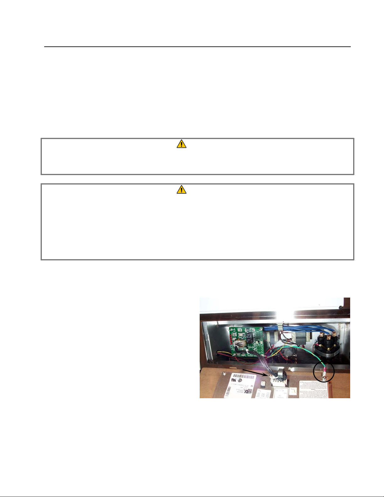
1. Unscrew and remove two control panel
screws on control panel front. Swing the
panel open from the top.
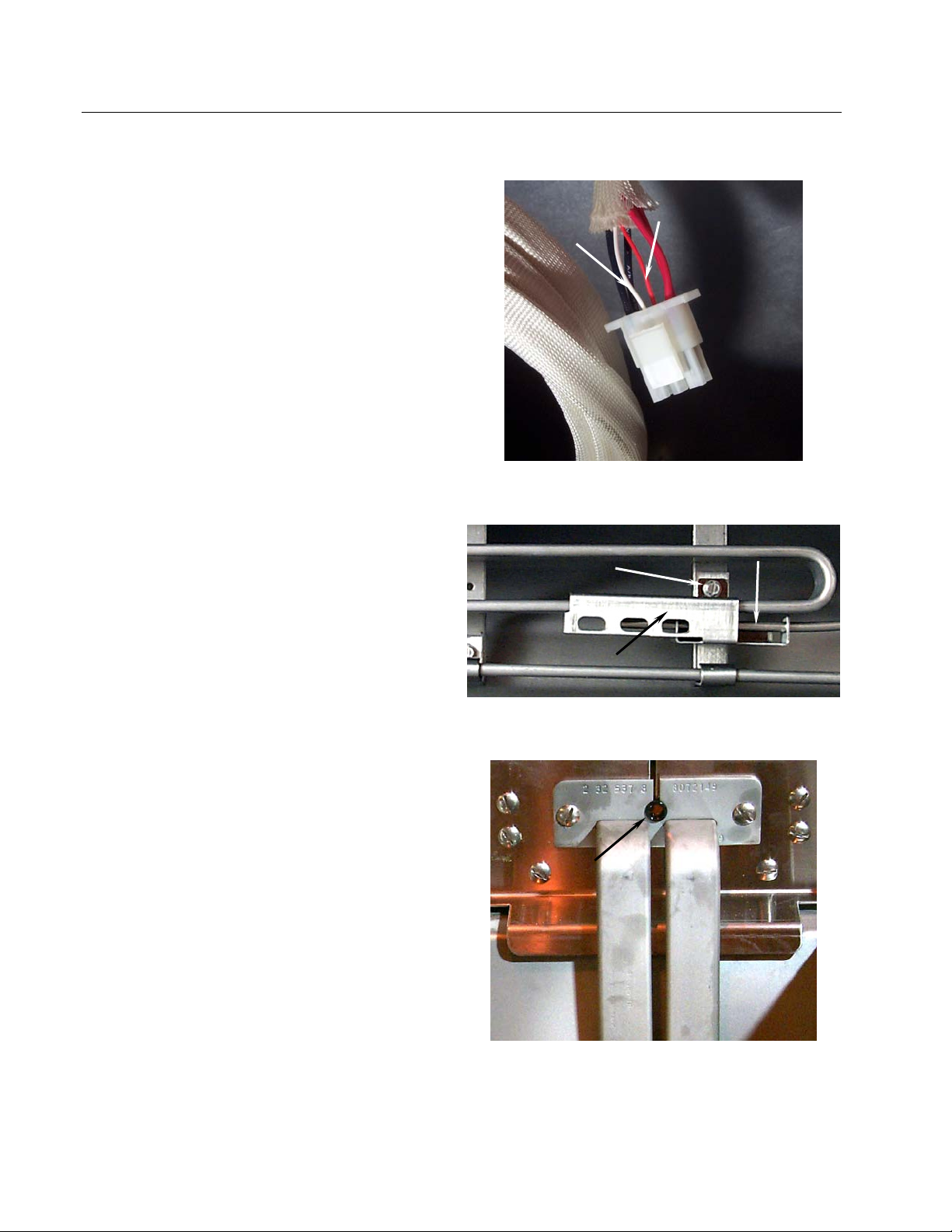
2. Unplug wiring harness at plug on back of
controller (arrow). Unplug controller ground
wire from controller (circle).
3. Remove the control panel/controller by lifting
the assembly from the hinged slots in the
control-panel frame.
4. Reverse procedures to install new controller.
Wire harness/connector and ground wire on controller
back.
1-1
Page 7
ULTIMATE ELECTRIC SERIES FRYERS
CHAPTER 1: SERVICE PROCEDURES
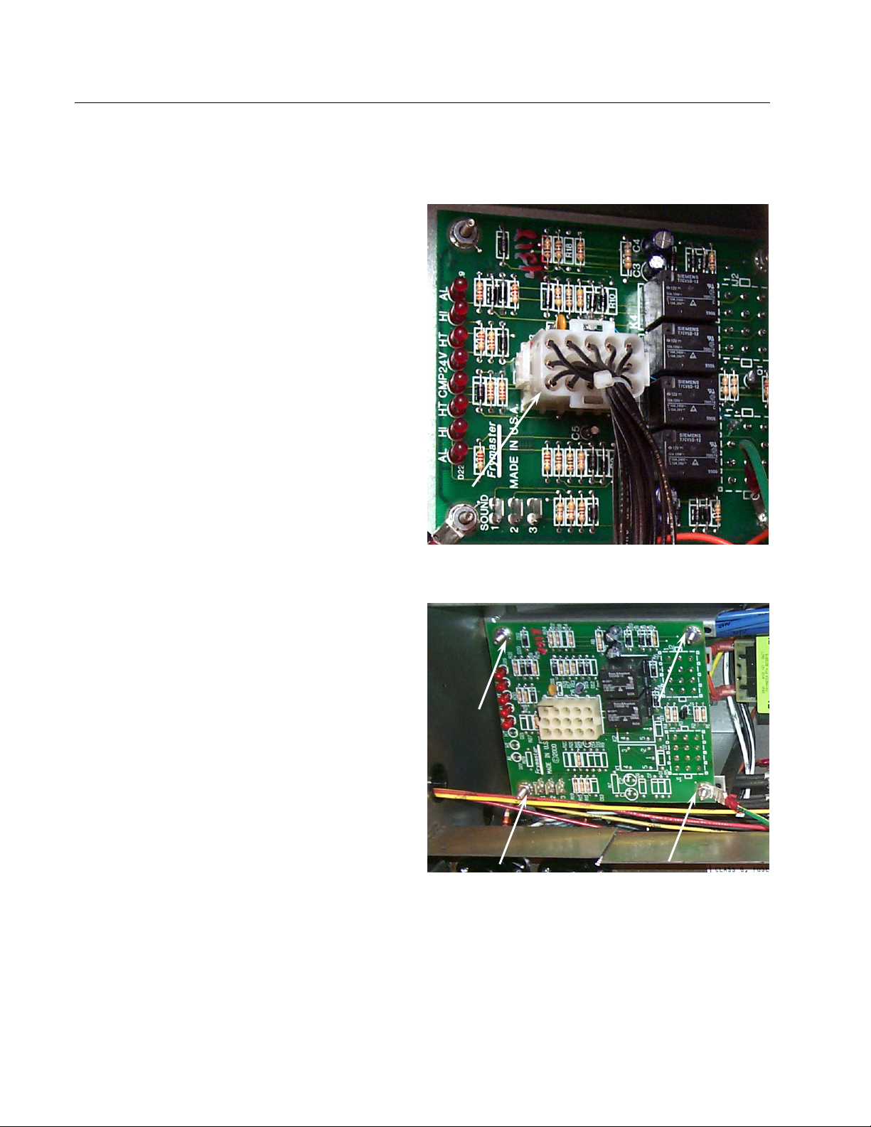
1.3 Replace Interface Board
1. Unplug all power cords. Perform Procedure 1.2, Steps 1-4, Replace Controller.
2. Unplug wire harness from the interface board
(arrow). Remove all wiring from the
terminals of the interface board, ensuring that
each wire is marked for reattachment.
3. Remove the nuts from each corner of the
interface board and slide the board from the
studs. Unplug connectors J1 and J2, mark
and unplug all other wiring on rear of the
interface board. Ensure that standoffs remain
in place on studs, prior to installing new
interface board. Install the new interface
board by reversing the previous procedures.
Ensure that wire harnesses are connected to
back of interface board prior to securing
interface board. Also, ensure that wiring and
wire harnesses are connected to the proper
terminals.
Wire harness/connector.
Nuts securing interface board (arrows).
1-2
Page 8
ULTIMATE ELECTRIC SERIES FRYERS
CHAPTER 1: SERVICE PROCEDURES
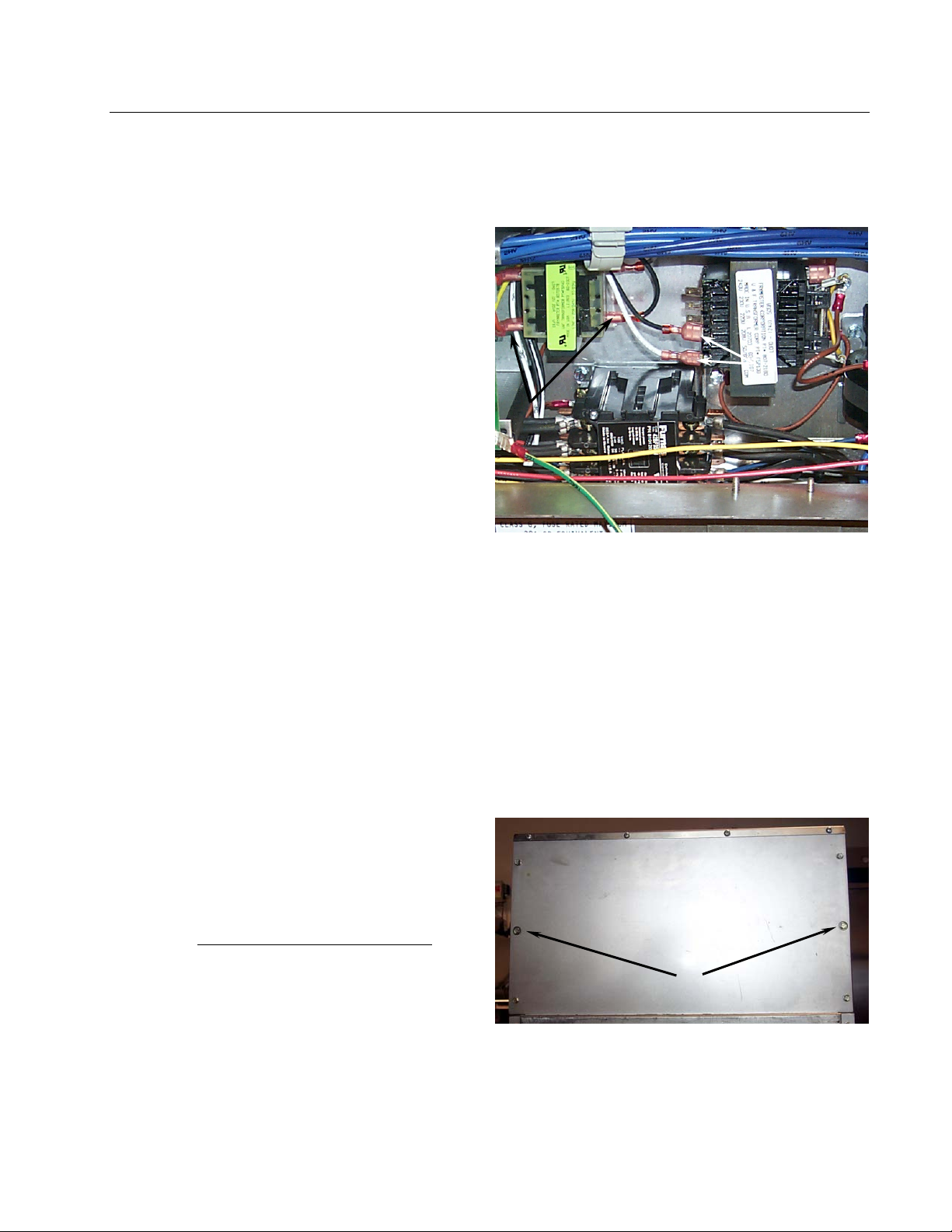
1.4 Replace Transformer
1. Unplug all power cords. Perform Procedure 1.2, Steps 1-4, Replace Controller.
2. Remove all wiring from the terminals of the
transformer to be replaced (arrows).
3. Remove the screws that secure the
transformer to the component box.
4. Install the new transformer by reversing the
preceding procedures. Make sure you
reconnect the wiring to the proper terminals
and the harnesses to the correct connectors.
Mark and disconnect wiring from the transformer
being replaced.
1.5 Replace Temperature Probe
1. Unplug fryer from the electrical source.
2. Drain the cooking oil from the frypot.
3. Remove the fryer from the exhaust hood to gain access to the rear of the fryer.
4. Remove the screws from the back cover(s).
Set the cover(s) and screws aside.
5. After removing back(s), remove two
remaining screws securing the tilt housing
cover (arrows). Remove the tilt housing.
Note: Early production model shown.
Current production units have a one-piece
back panel (remove all screws securing back
panel). Older units have a three-piece back
panel.
Screws securing back cover and tilt housing.
Remove two tilt-housing screws (arrows) after
removing all other screws and back panel(s).
1-3
Page 9
p
ULTIMATE ELECTRIC SERIES FRYERS
CHAPTER 1: SERVICE PROCEDURES
1.5 Replace Temperature Probe (cont.)
6. Disconnect the wire harness containing the
probe wiring (arrows). It may be necessary
to remove the wire ties.
7. Use a pin-pusher (P/N 806-4855 or P/N 807-
0928—see Section 1.7) to remove the red and
white probe wires from the connector. Note
probe pin location in plug. Pull the probe
wires out of the insulation.
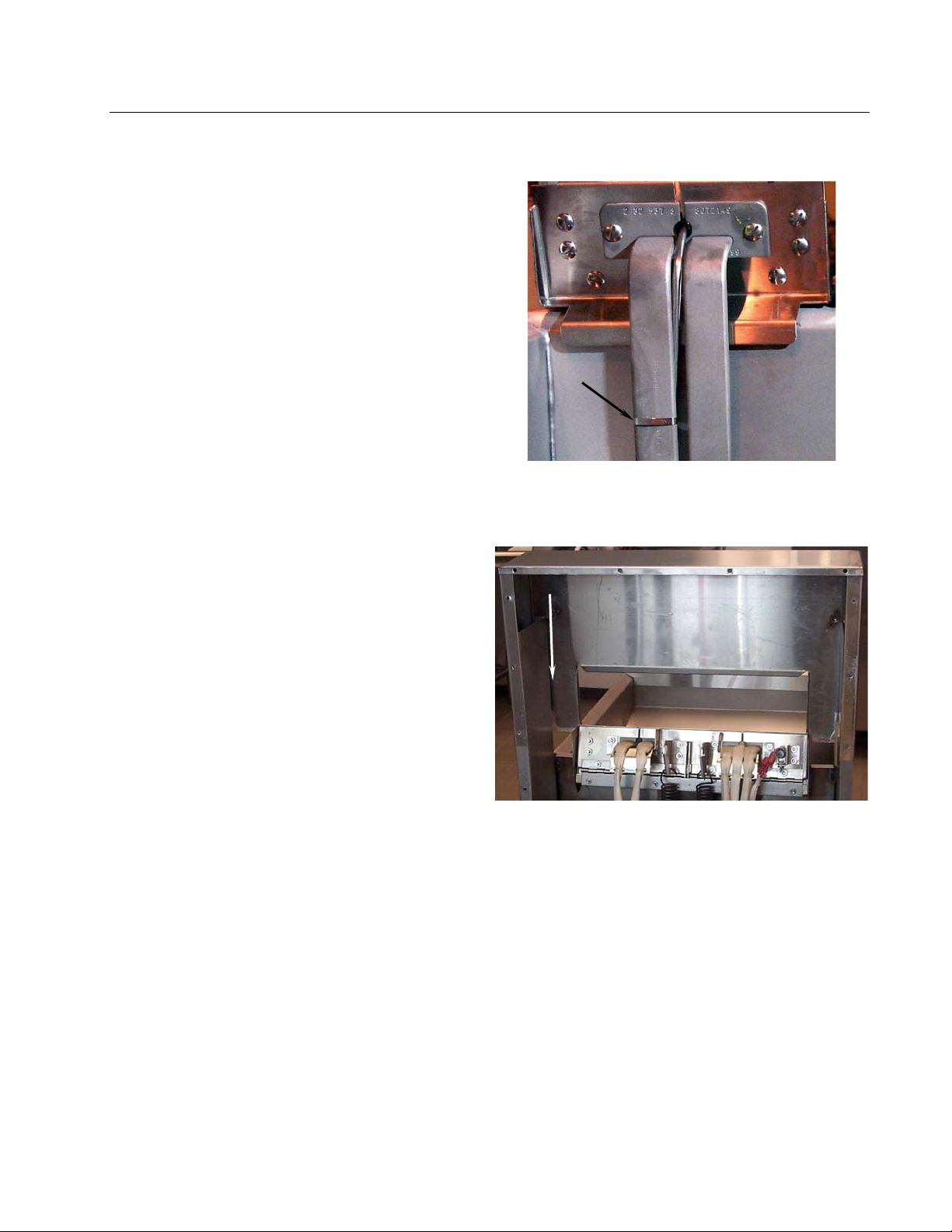
8. Remove the screw(s) securing the probe
bracket to the element. Remove the metal
wraps securing the probe to the element.
9. Remove the probe bracket and the securing
components from the probe bulb and element.
Thread the probe wire through the hole
(arrow) in the tilt plate assembly and remove
the probe.
Use a pin-pusher to remove probe wires from
connector (arrows).
Remove probe bracket screw and bracket to remove
robe.
Probe Bulb
Bracket Screw
Probe Bracket
Pull old probe wire through grommet to remove
probe.
1-4
Page 10
ULTIMATE ELECTRIC SERIES FRYERS
CHAPTER 1: SERVICE PROCEDURES
1.5 Replace Temperature Probe (cont.)
10. Thread the new probe wire through the hole
in tilt plate. Place the new temperature probe
assembly onto the element and secure with
the bracket and screws removed earlier. Clip
the probe onto the rear of the element (arrow)
in two places. The temperature probe
assembly should be oriented in the same
manner as the probe being replaced.
11. Thread the probe wires into the harness
insulation. Note the pin positions and insert
pins in the connector. Reconnect the harness
and secure with a wire-tie.
12. Lower the element into the frypot with the lift
handle.
13. Place the tilt housing cover over the tilt
housing assembly and secure with screws.
Slightly raising the elements will facilitate
tilt-housing installation.
14. Install back cover(s) and secure with screws
Secure probe bulb to the element back in two places
with metal wire wrap (arrow).
Install tilt housing and cabinet backs after probe
installation is complete.
1-5
Page 11
ULTIMATE ELECTRIC SERIES FRYERS
CHAPTER 1: SERVICE PROCEDURES
1.6 Replace Heating Element
1. Perform Procedure 1.5, Replace Temperature Probe, Steps 1-7.
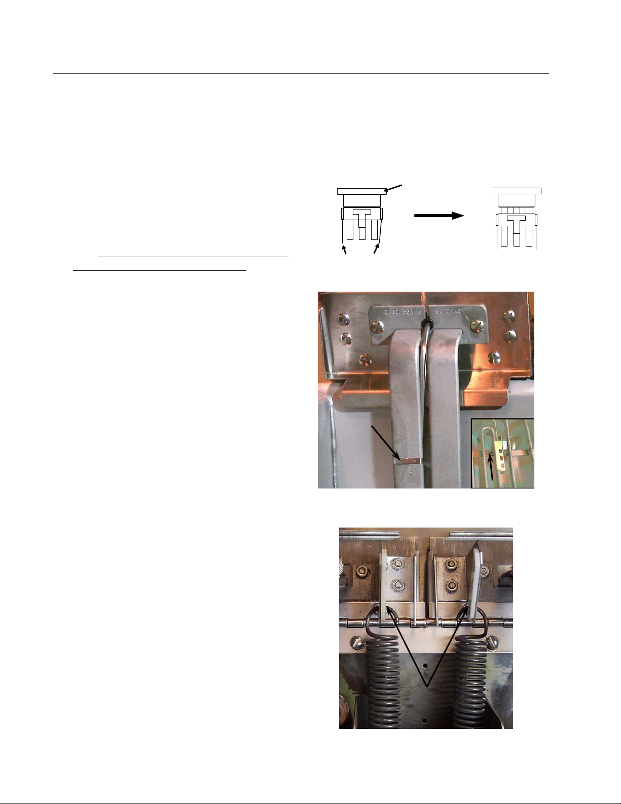
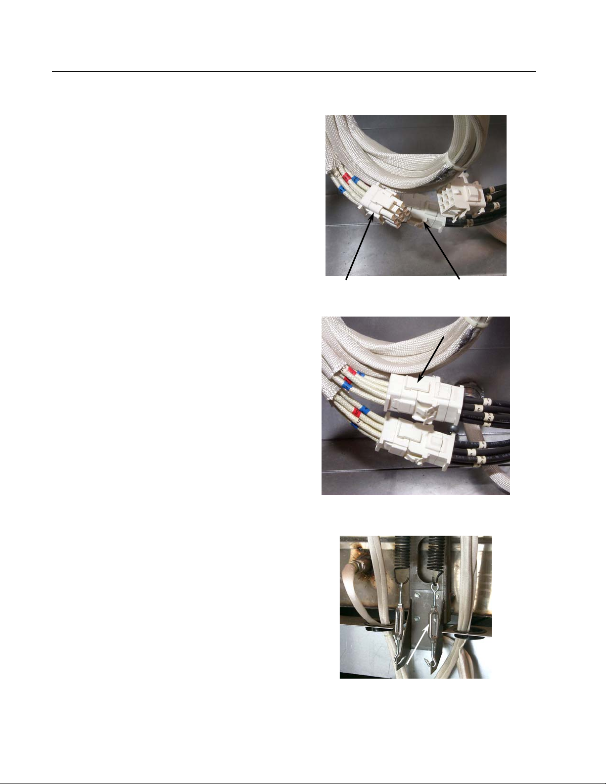
2. Unplug the element connectors for the
element being removed (right element- 6-pin
harness connector; left element- 9-pin harness
connector). Remove the element wires from
the connector. Press down on either side of
the connector while pulling up on the top
portion. The connector will open from the
top. Note wiring configuration in connector
before removing element wire pins. Pull all
wires from the connector.
3. Remove the screws securing the temperature
probe bracket from the element. Remove the
probe clamp (metal wire-wrap). Set the
temperature probe and probe-securing
components aside.
NOTE: Temperature probe removal is not
required if the left element is being replaced.
4. Disconnect the element springs from the tilt
brackets.
Push in on tabs to release
Remove metal wire wrap (arrow), and screws
securing probe bracket to element (inset, arrow).
Harness
Connector
Closed
top portion
Harness
Connector
Open
Top Portion
Disconnect element springs here.
1-6
Page 12
ULTIMATE ELECTRIC SERIES FRYERS
CHAPTER 1: SERVICE PROCEDURES
1.6 Replace Heating Element (cont.)
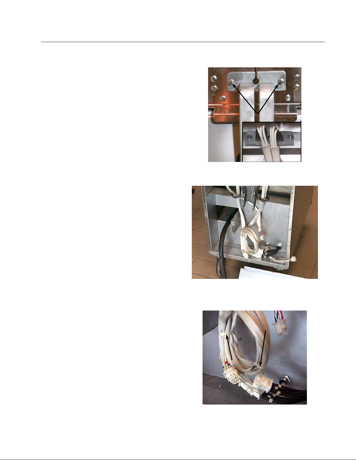
5. Remove the element clamps and hardware
before removing mounting-screws and nuts
on the defective element. Remove all wireties securing element wiring, and then
remove element from frypot.
6. Install the replacement element in the frypot
and secure with the mounting hardware
removed in Step 5.
7. Reinstall the temperature probe and probe-
bracket components onto the replacement
element.
8. Route the element leads (terminals) to the
rear of the fryer. Ensure the element-harness
insulation is in place prior to installing
connectors.
9. Secure element wiring with wire-ties.
Element mounting screws on tilt-plate front. (Inset:
element mounting plate on tilt-plate back.)
Ensure element wire insulation is installed and that
the wires are properly routed to prevent wire chafing.
Use wire-ties (arrows) to secure element wiring.
1-7
Page 13
ULTIMATE ELECTRIC SERIES FRYERS
CHAPTER 1: SERVICE PROCEDURES
1.6 Replace Heating Element (cont.)
10. When replacing the left element (as viewed
from the rear of the fryer), use the 9-pin
connector, inserting the leads from the
replacement element. Ensure the pin
numbers match the numbers of the defective
element wires. When all pin terminals have
been fully inserted, close the connector by
sliding the halves together until the tabs snap
back into place (reverse procedure in this
section, Step 2). Check wire numbers to
ensure correct wiring of the replacement
element.
When replacing the right element (as viewed
from the rear of the fryer), follow the above
procedure, inserting pin terminals into the
corresponding holes in the 6-pin connector.
11. Connect the connectors, ensuring the latches
lock in place (arrow).
12. Install the temperature probe wires (marked
for re-assembly) in the corresponding pin
locations.
13. Reconnect the element springs. Older models
have turnbuckles (arrow) to allow adjustment
of the spring tension.
14. Place the tilt housing cover over the tilt
housing assembly and secure with screws.
15. Install back covers and secure with screws.
16. Position fryer under exhaust hood.
Left Element—
9-Pin Connector
Right Element—
Connector
6-Pin
Ensure the connection is complete and the latches
(arrow) are locked in place.
Older units have turnbuckles to adjust spring tension.
Current production models are not adjustable.
1-8
Page 14
ULTIMATE ELECTRIC SERIES FRYERS
CHAPTER 1: SERVICE PROCEDURES
1.7 Replace High-Limit
1. Perform Procedure 1.5, Replace Temperature
Probe, Steps 1-4.
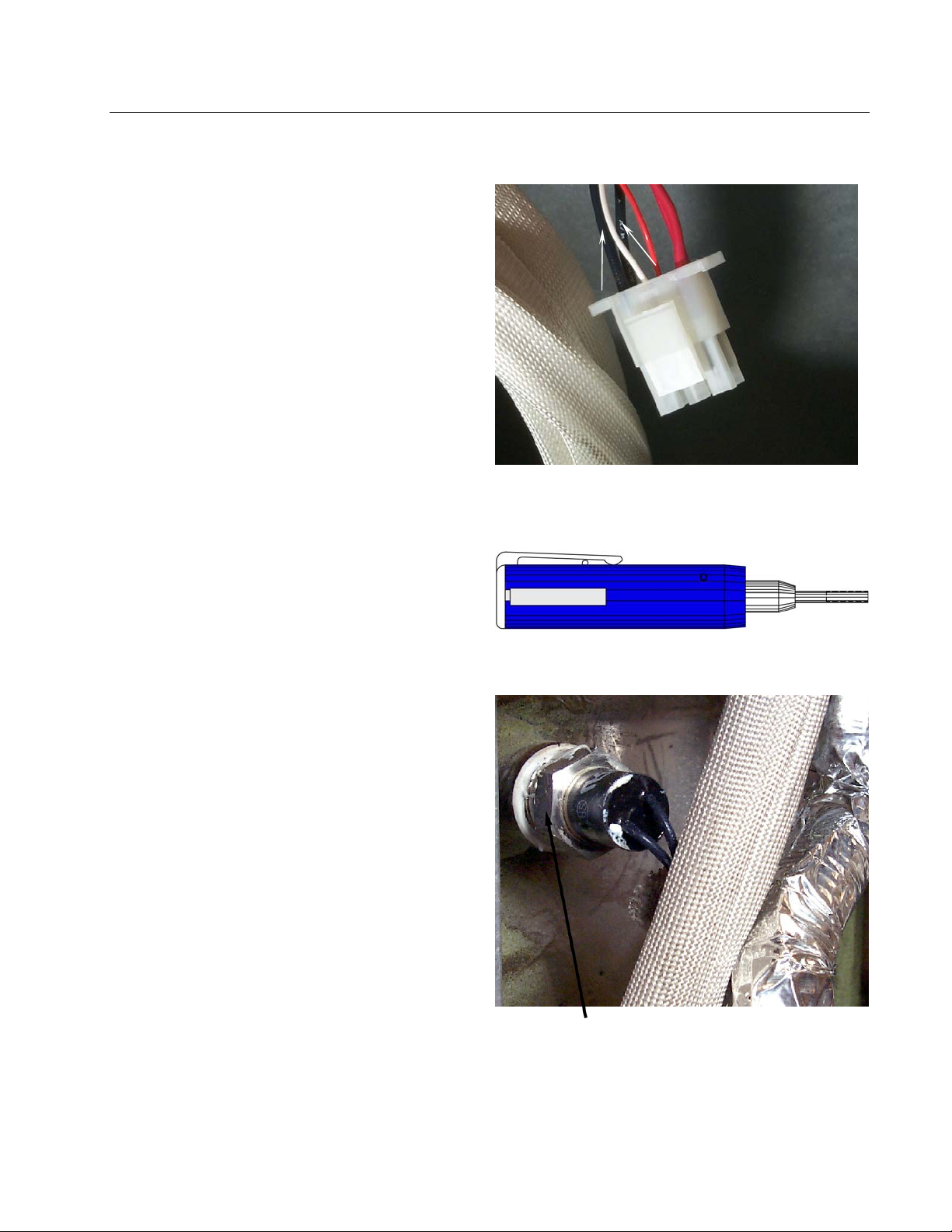
2. Disconnect the wire harness containing the
high-limit wires.
3. Use a pin-pusher (P/N 806-4855 or P/N 807-
0928) to remove the two high-limit wires
from the wire harness connector (arrows).
Note pin location in connector before
removing wires.
4. Remove the high-limit from the frypot using
an open-end wrench or other suitable tool.
5. Apply Loc-Tite PST 567 sealant to the
replacement high-limit threads.
6. Screw the replacement high-limit into the
frypot and tighten to 170-180 inch-pounds
torque. DO NOT OVERTIGHTEN.
7. Insert the replacement high-limit wires into
the connector, ensuring each wire is in the
correct hole..
8. Reconnect the high-limit wire-harness
connector.
9. Install and secure the back cover(s).
10. Return fryer to operation.
Using a pin-pusher, remove two high-limit wires
(arrows) from connector.
Pin Pusher— P/N 807-0928
Place wrench here when removing and installing
high-limit.
1-9
Page 15

ULTIMATE ELECTRIC SERIES FRYERS
CHAPTER 1: SERVICE PROCEDURES
1.8 Replace Frypot
1. Perform Procedure 1.5, Replace Temperature Probe, Steps 1-7.
2. Perform Procedure 1.2, Replace Computer/Controller, Steps 1-3.
3. Perform Procedure 1.7, Replace High-Limit, Steps 1-4.
4. Disconnect the element wire harnesses.
5. Remove the screws securing the capping piece from the fryer. Remove the capping piece and set
aside.
6. If the fryer has a built-in filtration system, remove all the plumbing from the frypot, including
oil-return and drain plumbing.
7. Remove the screws securing the frypot to the front frame of the fryer.
8. Carefully lift the frypot from the cabinet.
9. Remove the drain valve from the old frypot and install on the new frypot.
10. Apply Loc-Tite Sealant PST 567 to the high-limit threads. Install high-limit into the new frypot.
11. Disconnect the tilt plate springs from the old frypot.
12. Remove the securing screws from the tilt plate. Lift the tilt plate/heating element assembly from
the old frypot and install on the new frypot.
13. Follow the preceding steps in reverse to install the new frypot into the fryer.
14. NOTE: Apply Loc-Tite Sealant PST 567 to all pipefittings prior to installation.
1-10
Page 16
ULTIMATE ELECTRIC SERIES FRYERS
CHAPTER 1: SERVICE PROCEDURES
1.9 Replace Contactor (Latching or Heating)
1. Perform Procedure 1.2, Replace Computer/Controller, Steps 1-3.
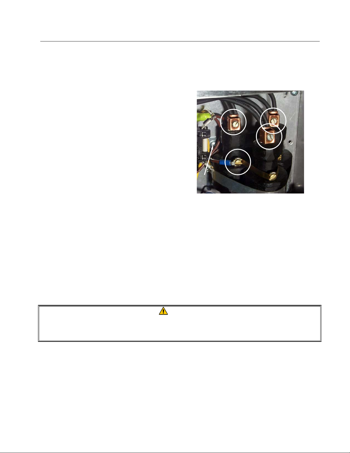
2. Identify faulty contactor. Remove all wiring
connected to the contactor terminals (circles)
inside the component box. Tape wire-pairs
together and mark each wire-set or wire for
reassembly.
3. Remove contactor-mounting screws (arrow)
and remove the contactor.
4. Install the new contactor and connect the
wiring removed in Step 2.
Remove contactor-mounting screws after removing
all wiring from the contactor (circles).
1.10 Built-in Filter System Service Procedures
Troubleshooting Built-In Filtration Systems
One of the most common errors is placing the filter paper on the bottom of the filter pan rather than
over the filter screen.
CAUTION
Ensure that the paper support screen is in place prior to filter paper placement and
filter pump operation. Improper screen placement is the major cause of filter system
malfunction.
Whenever the complaint is "the pump is running, but no oil is being filtered", check the installation
of the filter paper, and ensure that the correct size is being used. While you are checking the filter
paper, verify that the O-rings on the supply line connection are present and in good condition.
Missing or worn O-rings allow the pump to take in air, decreasing its efficiency. In addition, oil
leaks into the fryer and on the floor each time a frypot is filtered.
1-11
Page 17
ULTIMATE ELECTRIC SERIES FRYERS
CHAPTER 1: SERVICE PROCEDURES
1.10 Built-in Filter System Service Procedures (cont.)
If the pump motor overheats, a circuit breaker will trip and the motor will not start until the breaker
is reset. If the pump motor does not start, press the white reset button located under the component
box, inside the cabinet.
If the pump starts after resetting the breaker, then something is causing the motor to overheat. A
major cause of overheating is when several frypots are filtered sequentially, thus overheating the
pump and motor. Allow the pump motor to cool at least 30 minutes before resuming operation, and
allow time for the motor to cool between sequential frypot filtering.
Pump overheating can be caused by:
• Solidified shortening in the pan or filter lines,
or
• Attempting to filter unheated oil or shortening.
Cold oil and shortening are more viscous, causing the pump motor to load up and overheat. Always
filter with the oil or shortening at operating temperature [~350°F (177°C)].
If the motor runs but the pump does not, there is a blockage in the pump. Incorrectly sized or
installed paper/pads will allow food particles and sediment to pass through the filter pan and into the
pump. When sediment enters the pump, the gears bind, causing the motor to overload, again
tripping the thermal overload. Shortening that has solidified in the pump will also cause it to seize,
with the same result.
A pump seized by debris or hard shortening must be disassembled, cleaned, and then reassembled
before continuing use. Use the following procedure:
1. Disconnect power to the filter system.
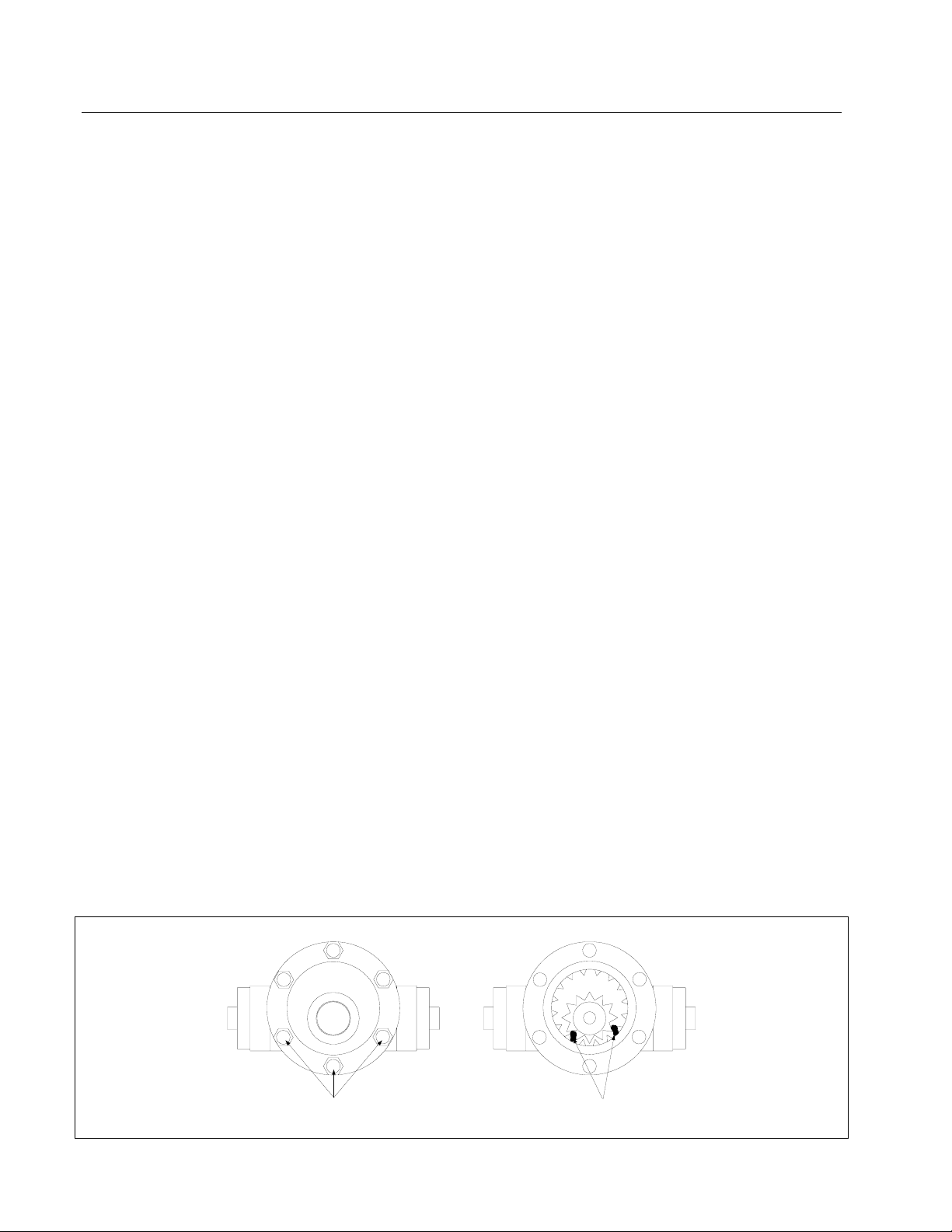
2. Remove the front cover of the pump to access the gears inside (see illustration below- 8-GPM
pump shown), if the pump is accessible while still inside the cabinet.
Remove bolts to remo ve
pump cover.
1-12
Remove debris or hardened
shortening to free gears.
Page 18
ULTIMATE ELECTRIC SERIES FRYERS
CHAPTER 1: SERVICE PROCEDURES
1.10 Built-in Filter System Service Procedures (cont.)
3. If the front cover is not accessible, the pump must be removed from the pump motor (remove
input/output plumbing from the pump prior to removing pump). Remove three setscrews from
the pump-shaft housing to disengage the pump from the motor. Remove the gears and
thoroughly clean all internal components. Ensure the inside of the pump housing is free of any
debris or hardened shortening before reassembling. Failure to completely clean the inside
housing and ring gear will cause gear binding after reassembly.
Filter paper/pads that are the wrong size or installed incorrectly will also allow food particles and
sediment to pass through and clog the suction tube in the bottom of the filter pan. Particles large
enough to block the suction tube may indicate that the crumb tray is not being used.
1.11 Basket Lift Service Procedures
Ultimate Electric Series fryers may optionally be equipped with automatic basket lifts to ensure
uniform cooking times. Electric fryers can be equipped with "modular" or "bell-crank" basket lifts.
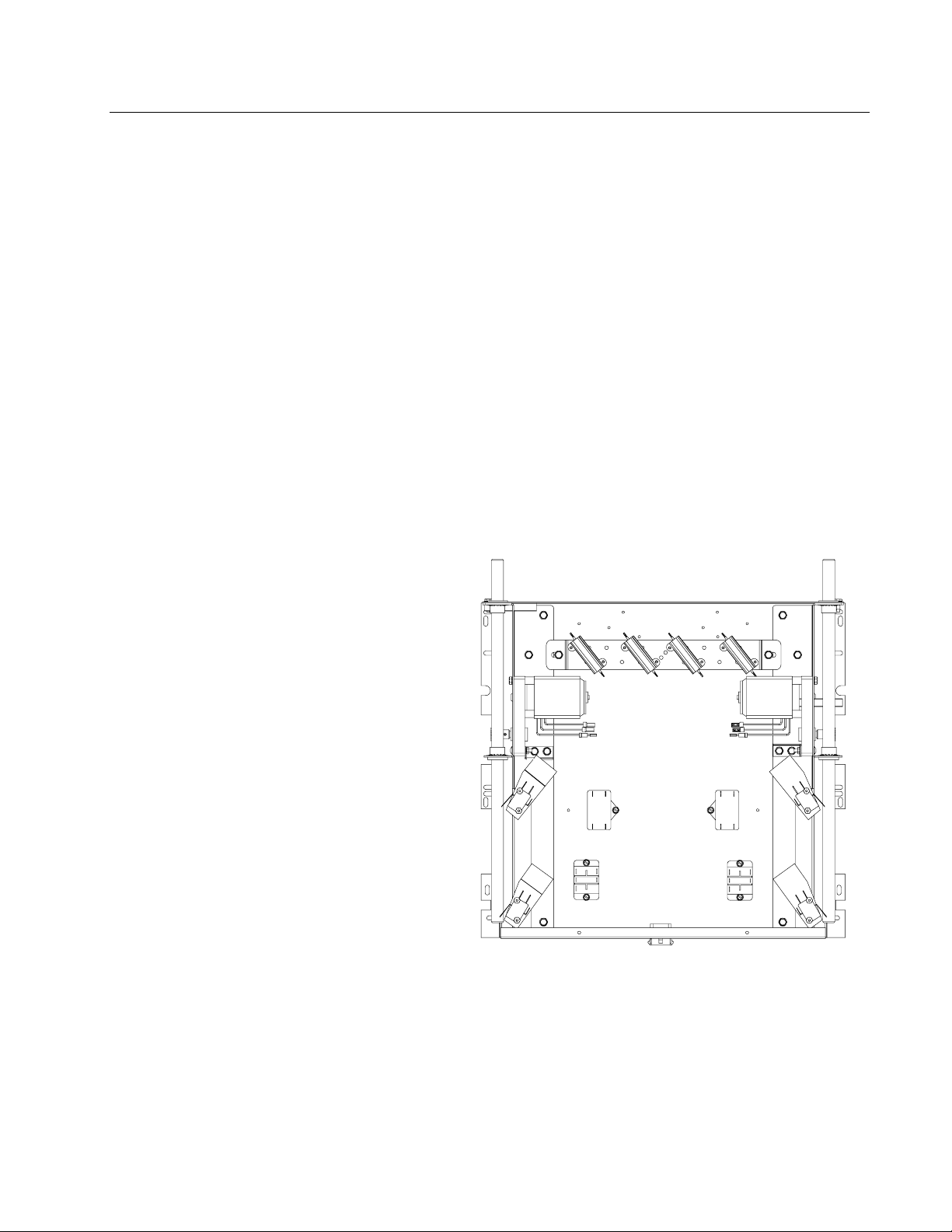
A modular basket lift (illustrated) consists
of a toothed rod to which the basket lift arm
is attached, a reversible-drive gear motor
and a pair of roller-activated microswitches.
The gear motor engages the teeth in the rod,
moving it up or down, depending upon the
direction of rotation of the motor.
Microswitches at the upper and lower limits
of movement stop the motor when the
basket is in the full up or full down position.
Timing circuitry in the controller initiates
and stops basket lift operation depending
upon the variables programmed by the
operator. When the product button is
pressed, or the manual control is activated,
the timing circuitry activates a coil in the
basket lift relay to supply power to the lower
microswitch. The microswitches stop the
motor at the lift’s upper and lower travel
limits and reverse the direction of current
flow thus reversing the motor direction.
Modular Basket Lift Assembly (Typical).
1-13
Page 19
ULTIMATE ELECTRIC SERIES FRYERS
CHAPTER 1: SERVICE PROCEDURES
1.11 Basket Lift Service Procedures (cont.)
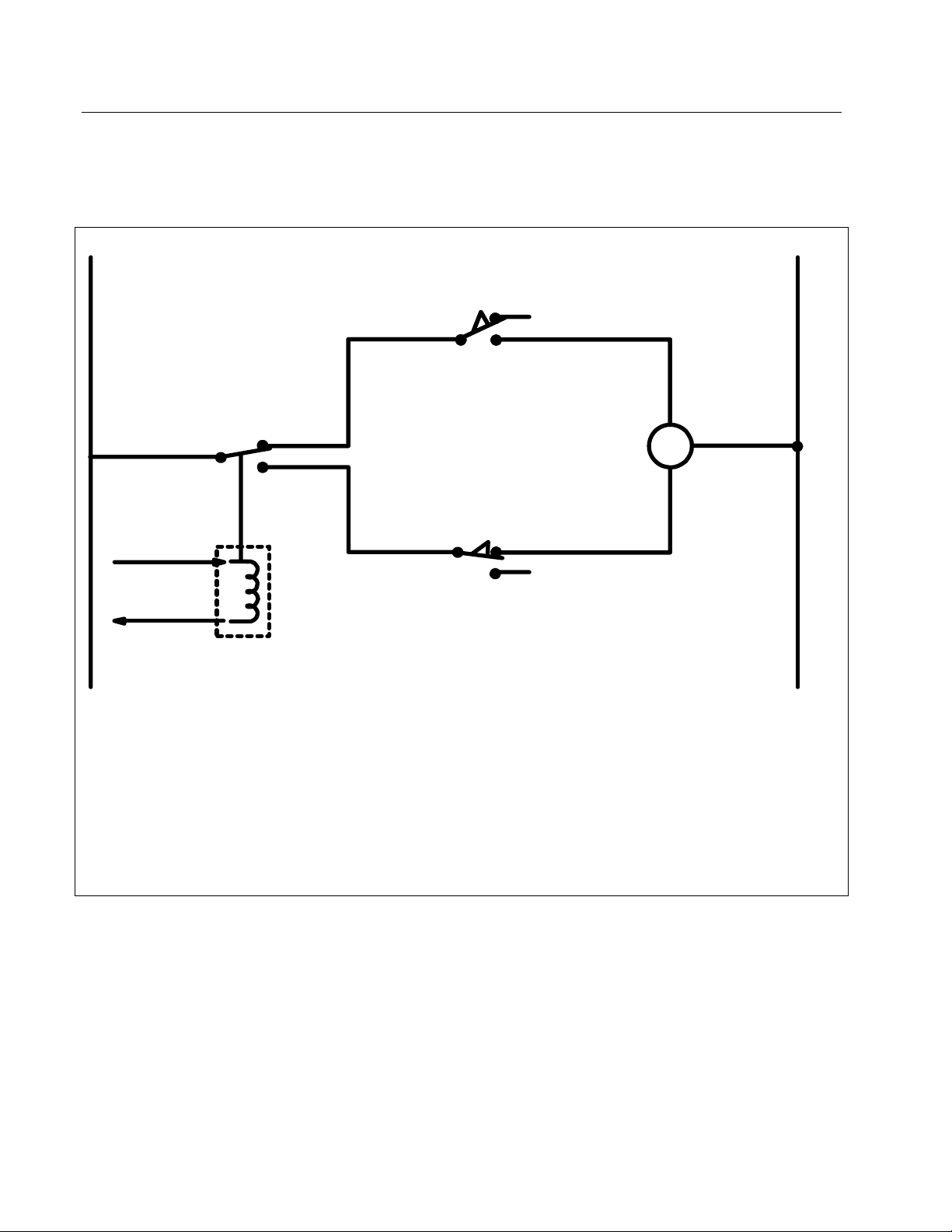
Simplified Schematic
H
5
1 or 4
3
To computer/controller via
interface board
Basket Lift
Relay
Normally Open Upper-limit
Microswitch
M
Normally Closed Lo wer-limit
Microswitch
N
6
When the product button is pushed on the computer/controller, current flows through a coil in the
basket lift relay, causing the lower circuit to be activated. The basket lift lowers, closing the
normally open upper-microswitch. When the lower normally closed microswitch is opened by the
downward moving lift rod, power to the motor ceases to flow. When the computer/controller timesout, the current to the relay coil is interrupted, allowing the upper circuit to be activated. The basket
lift then raises and closes the lower microswitch. When the basket lift rod clears the upper
microswitch, the microswitch opens, and power to the circuit is interrupted, stopping the motor.
Pushing the product button or activating the manual control (if equipped) restarts the cycle.
Problems with the modular basket lift design can be grouped into three categories:
● Binding/jamming problems
● Motor and gear problems
● Electronics problems
1-14
Page 20

ULTIMATE ELECTRIC SERIES FRYERS
CHAPTER 1: SERVICE PROCEDURES
1.11 Basket Lift Service Procedures (cont.)
BINDING/JAMMING PROBLEMS
Noisy, jerky or erratic movement of the lifts is usually due to lack of lubrication of the rods and their
bushings. Apply a light coat of Lubriplate or similar lightweight white grease to the rod and
bushings to correct the problem.
With the modular basket lift, another possible cause of binding is improper positioning of the motor,
which prevents the gear from correctly engaging the teeth in the rod. To correct the problem, loosen
the screws that hold the motor in place and move it forward or backward until the rod has just
enough slack to be rotated slightly.
MOTOR AND GEAR PROBLEMS
With the modular basket lift, the most likely problem to be encountered in this category is erratic
motion of the lift due to a worn drive gear. Failure to keep the lift rod and bushings properly
lubricated will cause unnecessary wear of the gear. The problem is corrected by replacing the worn
gear.
If the lift cycles correctly but fails to remain in the up position (i.e., goes up, but then slowly settles
back down into the frypot), the problem is a failed motor brake. The motor must be replaced.
If power is reaching the motor but the motor fails to run, the motor is burned out and must be
replaced.
ELECTRONICS PROBLEMS
Within this category are problems associated with the relays, microswitches, capacitors, resistors,
interface board, wiring, and controls. The most common problem in this category is a lift that
continuously travels up and down. This is usually caused by a microswitch that is out of adjustment.
Troubleshooting the electronics of a modular-type basket lift is simply a process of verifying current
flow through the individual components up to and including the motor. Using a multimeter set to the
250 VAC range, check the connections on both sides of the component for the presence of the
applied line voltage. The accompanying simplified wiring diagrams identify the components and
wiring connection points.
1-15
Page 21
ULTIMATE ELECTRIC SERIES FRYERS
CHAPTER 1: SERVICE PROCEDURES
1.11 Basket Lift Service Procedures (cont.)
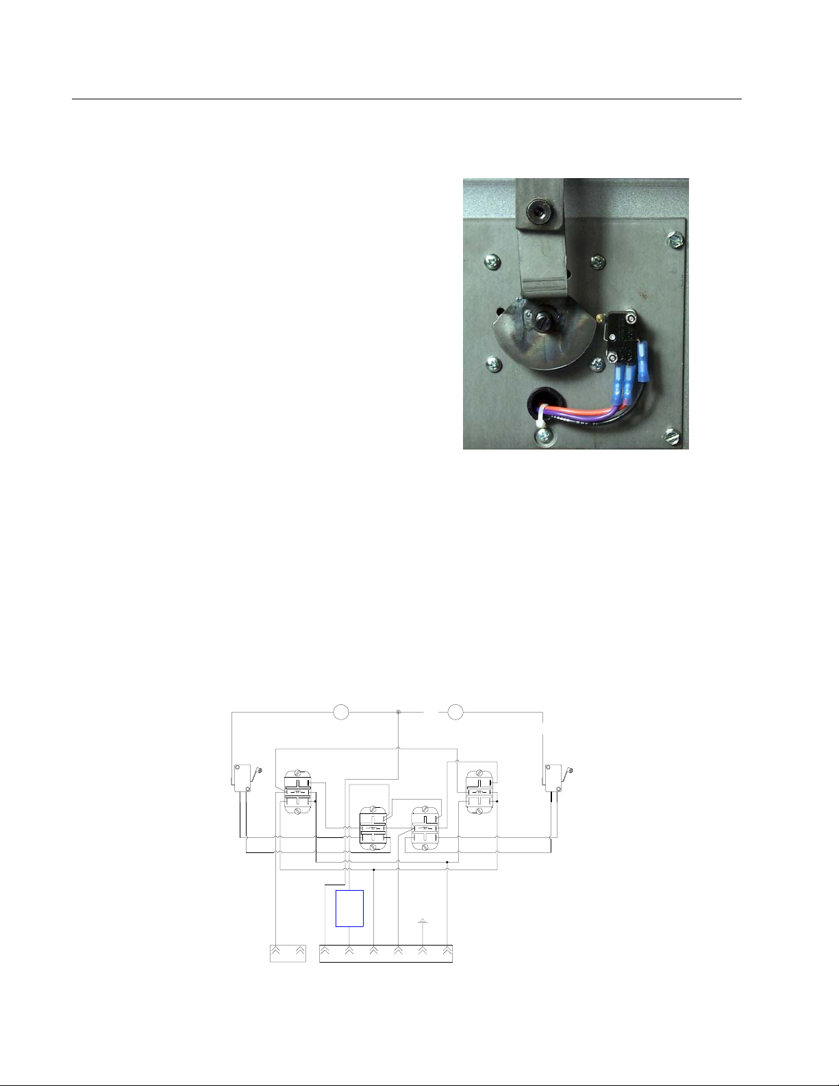
Ultimate Electric Series fryers, used to cook large
amounts of bone-in chicken in a single drop, are
equipped with bell-crank style basket lifts.
Two components, a cam and bell crank, are
connected to the basket lift arm by a flat metal
link. The cam is attached to a drive motor. The
motor rotates the cam, thus raising or lowering
the lift arm linked to the bell crank. A rolleractivated microswitch is used to limit travel.
When the roller in the microswitch is in contact
with the cam, the motor is energized. As the cam
rotates, the roller loses contact with the cam and
the motor power circuit is broken, de-energizing
the motor.
Bell-crank style basket lift.
Timing circuitry in the controller initiates and stops basket lift operation. When the product button is
pressed, the timing circuitry activates a coil in the basket lift relay to supply power to the motor. The
microswitch stops the motor at the lift’s lower travel limit and the switch contacts are reversed. At
the end of the programmed cooking time, the timing circuit activates the coil once more and the lift
rises until the microswitch again loses contact with the cam, opening the motor power circuit and
stopping the motor. A typical bell-crank wiring diagram is shown below.
REFERENCES TO LEFT & RIGHT ARE FROM REAR OF
FRYER
M
LH SIDE
ALL RELAYS
12VDC COIL
N.O.
N.C.
RED
BLU
132
NC
5 4
2 1
B.L.COM 2
COM
NO
6 5 4
WHT
COM
3
1
2 1
NC
NO
5
4
FUSE
5AMP
LINE LOAD
LINE COM
B.L. LH
WHT
RH SIDE
COM
3
2
NO
NC
5
4
3 2 1
GRD
B.L. COM
M
BLK
COM
3
1
2
NC
NO
5
4
B.L. RH
PUR
ORG
N.O.
N.C.
1-16
Page 22

ULTIMATE ELECTRIC SERIES FRYERS
CHAPTER 1: SERVICE PROCEDURES
1.12 Electric Interface Board Diagnostic Chart
The following diagram and charts provide ten quick system checks that can be performed using
only a multimeter.
Note: The sealed relays
are not replaceable. If a
relay fails, the interface
board must be replaced.
1
K1
K2
23
6
5
8
9
12
11
15
14
K3 K4
4
7
10
13
CMP indicates power from 12V transformer
24 indicates power from 24V transformer
HI (RH) indicates output (closed) from right latch
HI (LH) not applicable to Ultimate Electric fryers
HT (RH) indicates output from right heat relay
HT (LH) not applicable to Ultimate Electric fryers
AL (RH) indicates output (open) from right latch
AL (LH) not applicable to Ultimate Electric fryers
Diagnostic LED Legend
relay
relay
4
1
7
10
5
2
8
11
6
3
9
12
4
1
7
10
5
2
8
11
6
3
9
12
Meter Setting Test Pin Pin Results
12 VAC Power 50 VAC Scale 1 of J2 3 of J2 12-16 VAC
24 VAC Power 50 VAC Scale 2 of J2 Chassis 24-30 VAC
*Probe Resistance R X 1000 OHMS 11 of J2 12 of J2 See Chart
Hi-Limit Continuity R X 1 OHMS 7 of J2 4 of J2 0 - OHMS
Latch Contactor Coil R X 1 OHMS 8 of J2 Chassis 3-10 OHMS
Heat Contactor Coil R X 1 OHMS 9 of J2 Chassis 18-25 OHMS
*Disconnect 15-Pin harness from the computer/controller before testing the probe circuit.
1-17
Page 23

ULTIMATE ELECTRIC SERIES FRYERS
CHAPTER 1: SERVICE PROCEDURES
1.13 Probe Resistance Chart
Use the chart below when testing temperature probes and probe circuits for proper operation.
Probe Resistance Chart
F OHMS C F OHMS C F OHMS C F OHMS C F OHMS C
60 1059 16 130 1204 54 200 1350 93 270 1493 132 340 1634 171
65 1070 18 135 1216 57 205 1361 96 275 1503 135 345 1644 174
70 1080 21 140 1226 60 210 1371 99 280 1514 138 350 1654 177
75 1091 24 145 1237 63 215 1381 102 285 1524 141 355 1664 179
80 1101 27 150 1247 66 220 1391 104 290 1534 143 360 1674 182
85 1112 29 155 1258 68 225 1402 107 295 1544 146 365 1684 185
90 1122 32 160 1268 71 230 1412 110 300 1554 149 370 1694 188
95 1133 35 165 1278 74 235 1422 113 305 1564 152 375 1704 191
100 1143 38 170 1289 77 240 1432 116 310 1574 154 380 1714 193
105 1154 41 175 1299 79 245 1442 118 315 1584 157 385 1724 196
110 1164 43 180 1309 82 250 1453 121 320 1594 160 390 1734 199
115 1174 46 185 1320 85 255 1463 124 325 1604 163 395 1744 202
120 1185 49 190 1330 88 260 1473 127 330 1614 166 400 1754 204
125 1195 52 195 1340 91 265 1483 129 335 1624 168 405 1764 207
1.14 Element Wattage/Amperage Calculation Charts
Use the charts below when changing voltages or determining amperage for a given element
configuration.
L1
L1
Three Phase
Amperage
L2
L3
To determine Three P hase Amperage, solve fo r
Single Phase first:
Wattage
Voltage
Then divide the Single Phase Amperage by 1.73 to
determine Three Phase Amperage.
Example:
17,000W
= 40.944 Amps per Phase
= Single Phase Amps
70.833 Amps
240V
=
1.73
Three Phase
Wattage
L2
L3
To compute the New Wattage Rating of an element if a
different voltage is applied, use the following formula:
208V
240V
2
2
kW Listed
X
X
17,000 Watts
New Voltage
[]
Old Voltage
= New Wattage Rating
Example:
If 208V supply is applied to a 17 kW element
rated for 240V, the calculation is as follows:
[]
= 12.77 kW
1-18
Page 24

ULTIMATE ELECTRIC SERIES FRYERS
CHAPTER 1: SERVICE PROCEDURES
1.15 Wiring Diagrams, Main
1.15.1 Wiring Diagram, Main- 208/240V: 1721, 18E and 18UE
1-19
Page 25

ULTIMATE ELECTRIC SERIES FRYERS
CHAPTER 1: SERVICE PROCEDURES
1.15.2 Wiring Diagram, FAST: 1721, 18E and 18UE
1-20
Page 26

ULTIMATE ELECTRIC SERIES FRYERS
CHAPTER 1: SERVICE PROCEDURES
1.15.3 Wiring Diagram, Main- KSCFH218E FAST Export (India)
1-21
Page 27

ULTIMATE ELECTRIC SERIES FRYERS
CHAPTER 1: SERVICE PROCEDURES
1.15.4 Wiring Diagram, Main- 480V: 18UE and EH1721
L1
L3
L2
1,2
3,6
4,5
3 WIRE
3 PHASE
5
4
3
DRAIN
2
SWITCH
BLK 48C
6
RED 39C*
RED 38C*
Lift Position
* Non Basket
RED 30C
RED 31C
YEL 72C
480V ELEMENTS
R
L
9
76 854312
5 632 4
1
HEAT
CONTACTOR
LATCH
CONTACTOR
GROUND
TERMINAL
BLU 6H
BLU 6H
BLU 2H
BLK 5H
BLK 3H
BLK 1H
480V
BRN 40C
K2
624
120V
3 51
K1
BRN 40C
WHT 42C
ORG 15C
ORG 14C
12V
120V
1
9
11 1298 10
6 7345
12
TERMINAL
BLOCK
8051401D
15141310 11 12985 6 7341 215
(NO. 8067158)
FRY CM 3.5 COMPUTER
TO INTERFACE BOARD
J1
9
14
131110 1287 965
4
321
BOARD (NO. 8067965)
COMPUTER INTERFACE
TO FRY BM 3.5 COMPUTER
GND
J2
1298 10
11
67345
12
YEL 12C
BRN 40C
RED 73C
24V
120V
21436 5
GRN/YEL 74C
To Basket Lift
FUSE
BLK 5C
WHT 4C
WHT 1C
FUSE
BLK 6C
WHT 3C
BLK 2C
BLK 71C
T1
WHT 70C
T2
PUR 75C
RED 34CBLK
C6
BLU 29C
BLU 28C
HIGH LIMIT
THERMOSTAT
NC
C
BLU 36C
BLU 37C
RED 35C
RED 32C
WHT 33C
432
6
5
432
6
5
1 1
RED
BLK
WHT
BLU 61C
BLU 60C
RED
WHT
PROBE
TILT SWITCH
1-22
Page 28

ULTIMATE ELECTRIC SERIES FRYERS
CHAPTER 1: SERVICE PROCEDURES
1.15.5 Wiring Diagram, Main- 208V- 18UE and EH1721
GROUND
TERMINAL
BLU 6H
BLU 6H
BLU 2H
BLK 5H
BLK 3H
R
9
76 854312
5 632 4
208V ELEMENTS
1
L
HEAT
BRN 40C
CONTACTOR
K2
624
3 51
K1
BRN 40C
LATCH
CONTACTOR
BLK 1H
WHT 42C
ORG 15C
ORG 14C
12V
208V
4 WIRE
3 PHASE
L41,3,5
5
YEL 72C
L24
L3
2L1
6
3
2
641
TERMINAL
3 WIRE
BLOCK
3 PHASE
L1
L3
L2
1,2
3,6
4,5
2
5
4
3
6
BLOCK
TERMINAL
1
8051412A
15141310 11 12985 6 7341 215
SWITCH
DRAIN
(NO. 8067158)
TO INTERFACE BOARD
FRY CM 3.5 COMPUTER
BLK 48C
J1
9
9
BOARD (NO. 8067965)
COMPUTER INTERFACE
GND
14
131110 1287 965
4
TO FRY BM 3.5 COMPUTER
321
11 1298 10
6 7345
12
1298 10
11
67345
12
J2
YEL 12C
BRN 40C
RED 73C
BLU 28C
24V
208V
21436 5
GRN/YEL 74C
To Basket Lift
FUSE
BLK 5C
WHT 4C
WHT 1C
FUSE
BLK 6C
WHT 3C
BLK 2C
BLK 71C
T1
WHT 70C
T2
PUR 75C
RED 34CBLK
C6
BLU 29C
BLU 28C
HIGH LIMIT
THERMOSTAT
NC
C
BLU 36C
BLU 37C
RED 35C
RED 32C
WHT 33C
432
6
5
432
6
5
1 1
RED
BLK
WHT
BLU 61C
BLU 60C
RED
WHT
PROBE
TILT SWITCH
1-23
Page 29

ULTIMATE ELECTRIC SERIES FRYERS
CHAPTER 1: SERVICE PROCEDURES
1.15.6 Wiring Diagram, Main- KSCFH218E
HEATING
ELEMENT
6C
L3
6C
4C
L2
4C
CYCLING
2C
CONTACTOR
L1
2C
6
54321
9
6
3
2
8
5
1
7
4
77C
76C
24C
27C
26C
25C
L2
L1 L3
LATCH CONTACTOR
6C
6C
4C
4C
2C
2C
CYCLING
CONTACTOR
60A FUSE EACH
FUSE BLOCKS
23C
22C
21C
L3
19C
L2
L1
20C
18C
L2
L3
16C
L1
GROUND
L3L2
17C
L1
BLOCK
TERMINAL
LATCH
CONTACTOR
DELTA
3 PHASE, 3 WIRE
LATCH CONTACTOR
1C ARE ELIMINATED
WIRE 7C GOES FROM
HOLDER AND WIRE
NOTE: RIGHT FUSE
TO T2.
24C
23C
8C
22C
27C
26C
25C
7C TO T2
GROUND
L3
L2
L1
N
BLOCK
TERMINAL
KSCFH218
4 WIRE WYE
CONNECTION
65432
TILT
SWITCH
58C
WHT
RED
3
614
5
2
1
4
5C
3C
5C
3C
1C
1C
12
7
4
8
5
9
1C
3C
1C
3C
5C
4
5
6
6
5
4
2C
6
3
4C
6C
5C
2C
4C
1
2
3
3
2
1
CABLE TO REAR
24V
TRANSF
240
220
230
208
COM
6C
3C
5C
12C
HEATING
ELEMENT
COM
208V
12V
TRANSF
1
8C BLK
TO
FILTER
75C
RED
BLK
SPEAKER
44C
DRAIN SWITCH
43C
7
9
8
6C
T1T2
4C
240V
15C
14C
4563
1
2
COMPUTER (BACK)
13C
33C
36C
32C
59C
5
2
3
6
OIL
SENSOR
ON ELEMENT
TEMPERATURE
34C
35C
33C
32C
36C
37C
CABLE TO REAR
35C
34C
6
3
1210 11
2
5
897
1
4
654
11 1210
1 2 3
7 89
15 PIN CABLE
37C
BOARD
INTERFACE
2C BLK
8C BLK
41C
110C
1C WHT
7C WHT
FUSE
HOLDER
FUSE
HOLDER
AMP
PINS
FEMALE
8051429B
HIGH LIMIT
BLK
FLOAT
SWITCH
BLK
AMP
PINS
MALE
1-24
Page 30

ULTIMATE ELECTRIC SERIES FRYERS
CHAPTER 1: SERVICE PROCEDURES
1.15.7 Wiring Diagram, Main- BIH1721
R
6 7 8 9
6H BLU
CONTACTOR
HEAT
132 54
6
208V OR 240V ELEMENTS
1 3254
L
K2
K1
LATCH
CONTACTOR
37C BLU
4H BLU
41C BRN
40C BRN
2H BLU
5H BLU
64231 5
3H BLU
1H BLU
42C WHT
15C ORG
14C ORG
BLOCK
240V ONLY
4 WIRE
1514
1311 126 7891034512
TERMINAL
N
L2
L1
L3
L4
3 PHASE
331
5
2,4,6
4
2
6
1
5
BLOCK
TERMINAL
GROUND
3 WIRE, 3 PHASE
FUSES USED ONLY FOR
NC
COM
SWITCH
DRAIN
L3
3 WIRE, 3 PHASE
3,6
6
3
1C WHT
20A
FUSE
NO
48C BLK
12
119107856
3421
TERMINAL
L1
L2
1,2
4,5
1
5
2
4
12
119107856
3421
BOARD (NO. 806-7965)
COMPUTER INTERFACE
J2
GND
32C RED
36C BLU
34C RED
35C RED
33C WHT
37C BLU
1
453
66
12V
240V
28C BLK
29C WHT
6C BLK
3C WHT
24V
240V
20A FUSE
BLK
WHT
2C BLK
T1
T2
2
C6
YEL
YEL
29C WHT
3
4
5
2
1
RED
BLK
WHT
61C BLU
RED
60C BLU
NC
BLK
C
HIGH LIMIT
THERMOSTAT
SWITCH
BY-PASS
BLK 10C
BLK 23C
BLK 26C
BLK 20C
WHT
PROBE
TILT SWITCH
POSITION
MICRO SWITCH83C
OIL RETURN
SHOWN IN OFF
WHT 22C
NC
NO
COM
NC
NO
RELAY
WHT 46C
BLK 11C
YEL
24V
COM
T8
RED 25C
RED 80C
LOW VOLTAGE SHOWN
24V
WHT 45C
T5
CB
HIGH VOLTAGE SHOWN
CIRCUIT
BREAKER
WHT
ON THE MOTOR
MOTOR
FOR CHANGE OF ROTATIO N
INTERCHANGE LEADS T5 AND T8
T2T4T3P2T5
T4
T8
T3
2 AMP FUSE
HEAT TAPE - 25 WATT
P1
WHT
RED
TAIL
BOMB
P2
T2
P1
100C WHT
101C RED
BLK
104C WHT
105C BLK
BOMB TAIL
8051445B
1-25
Page 31

ULTIMATE ELECTRIC SERIES FRYERS
CHAPTER 1: SERVICE PROCEDURES
1.16 Wiring Diagrams, Basket Lifts
1.16.1 Modular Basket Lifts
LEFT
SIDE
RESISTORS**
RIGHT
SIDE
MM
NO
NC
UPPER
SWITCH
NO
NC
LOWER
SWITCH
COM
COM
COM
1
NC
4 3 26 5
LIN COM
LINE LOAD
**120V UNITS: TWO 13 OHM
**208-220V UNITS: FOUR 50 OHM
3
2
NO
45
1
GND
B.L. LH
B.L. RH
B.L. COM
12.5 µF12.5 µF
NC
NO
COM
COM
3
2
1
NO
NC
45
UPPER
SWITCH
NO
COM
NC
LOWER
SWITCH
240V Basket Lifts OnlyThree Sets of Resistors
LEFT SIDE RIGHT SIDE
MM
25 Ohm 25 Ohm
50 Ohm
1-26
Page 32

ULTIMATE ELECTRIC SERIES FRYERS
CHAPTER 1: SERVICE PROCEDURES
1.16.2 Bell-Crank Style Basket Lifts
REFERENCES TO LEFT & RIGHT ARE FROM REAR OF FRYER
M
LH SIDE
WHT
RH SIDE
M
BLK
ALL RELAYS
12VDC COIL
COM
N.O.
N.C.
132
NC
5 4
NO
RED
WHT
1
NC
5
COM
3
2 1
NO
4
COM
3
2
NO
NC
5
4
BLU
FUSE
5AMP
2 1
6 5 4
3 2 1
COM
3
1
2
NC
NO
5
4
N.O.
N.C.
PUR
ORG
LINE LOAD
B.L.COM 2
LINE COM
B.L. LH
GRD
B.L. COM
B.L. RH
1-27
Page 33

ULTIMATE ELECTRIC SERIES FRYERS
CHAPTER 1: SERVICE PROCEDURES
1.17 Wiring Diagrams: Built-in Filtration
1.17.1 Wiring Diagram, 480V Systems With Built-in Filtration
NC
NO
RED 82C
COM
YEL 85C
NC
NONO
RED 81C
YEL 84C
(TRIPLE)(DOUBLE)
RH FRYER
OIL RETURN
OIL RETURN
CENTER FRYER
MICROSWITCH
8051403F
SHOWN IN
OFF POSITION
SCF OIL RETURN
TRANSFORMER/RELAY ASSY
NC
RED 80C
COM COM
NC
NO
24V
COM
YEL 83C
LH FRYER
OIL RETURN
RELAY
BLK 26C
BLK 23C
RED 25C
MOTOR
24V
120V
BLK 20C
WHT 45C
WHT 46C
T8T4T2
LOW VOLTAGE SHOWN
T3
T5
P2
T4
T5
T2
T3
T8
LEADS T5 AND T8 ON THE MOTOR
P1
FOR CHANGE OF ROTATION INTERCHANGE
HEAT TAPE - 25 WATT
GRN
FUSE
2 AMP
J BOX
FUSE HOLDER
FUSE
JUCTION BOX
COVER PLATE
P2
P1
HIGH VOLTAGE SHOWN
5 AMP-480V
CB
BLK 11C
115V
INPUT
CIRCUIT
7 AMP-120V
CIRCUIT BREAKER
WHT#1
BLK
WHT#2
BLK #2
1-28
Page 34

ULTIMATE ELECTRIC SERIES FRYERS
CHAPTER 1: SERVICE PROCEDURES
1.17.2 Wiring Diagram, 208V Systems With Built-in Filtration
SCF OIL RETURN
TRANSFORMER/RELAY ASSY
BLK 10C
NC
NO
RED 82C
YEL 85C
RED 81C
BY-PASS SWITCH
BLK 26C
BLK 23C
WHT 22C
NC
NO
24V
COM
RELAY
PN 1932
RED 25C
YEL 84C
RED 80C
YEL 83C
COM
NC
NC
COM COM
RH FRYER
OIL RETURN
NONO
OIL RETURN
CENTER FRYER
LH FRYER
OIL RETURN
8051413A
(TRIPLE)(DOUBLE)
OFF POSITION
MICRO SWITCH SHOWN IN
MOTOR
LEADS T5 AND T8 ON THE MOTOR
T5T4T2
T8
T3
208V
24V
P2
FOR CHANGE OF ROTATION INTERCHANGE
P1
HIGH VOLTAGE SHOWN
BLK 20C
T4
T5
WHT 45C
WHT 46C
CB
BLK 11C
208V
INPUT
CIRCUIT
LOW VOLTAGE SHOWN
WHT#1
P2
T2
T3
T8
P1
BLK
1-29
Page 35

ULTIMATE ELECTRIC SERIES FRYERS
CHAPTER 1: SERVICE PROCEDURES
1.17.3 Wiring Diagram, 115/230V KFC Systems With Built-in Filtration
BLK
BLU
115V
230V
TO 24 VAC
115 VAC OR 230 VAC
RH FRYER TRANFORMER
RH FRYERLH FRYER
WHT
INPUT
115V/230V
FILTER CIRCUIT
24V OUT
YEL
CIRCUIT
YEL
TO RH FRYER
CIRCUIT
BREAKER
115 V - 7 AMP
BLK
BLK
BLK
CB
230 V - 5 AMP
8051366B
SWITCH
MANUAL
ORG
YEL
YEL
24V
ORG
BLK
NC
NO
24V
COM
PUR
RED
YEL #1
NC
NO
24V
COM
BY PASS
YEL #1
2
1
YEL
WHT
PUR
YEL
ORG
KSCFH18E FILTER CIRCUIT
NC
RED
2
1
COM
NO
OIL RETURN
MICROSWITCH
MOTOR
T5
T4
T8T2T3
T1
LEADS T5 AND T8 ON THE MOTOR
FOR CHANGE OF ROT AT I ON I NTE RC HA NGE
WHT
PUR
ORG
YEL
2
1
11
2
1
WHT#1
NC
2 2
COM
BLK
NO
OIL RETURN
MICRO SWITCH
1-30
Page 36

ULTIMATE ELECTRIC SERIES FRYERS
2.1 Accessories
CHAPTER 2: PARTS LIST
1
2
5
3
4
6
7
Item Part Number Description
1 810-2092 Basket Hanger
* 106-1968 Cover, Vat- All Ultimate Electrics
2 809-0171 Thumbscrew, Basket Hanger
3 210-1288 Joiner Strip
4 803-0209 Brush, Frypot
* 810-2120 Grid, Frypot W/Standoff
* 803-0149 Grid, Frypot- FPH1721 Systems
5 803-0306 Fry Basket, Twin Basket
* 803-0017 Fry Basket, Full Basket
6 826-1117 Caster, 5"- W/O Brake (Mounting Hardware Included)
7 826-1118 Caster, 5"- With Brake (Mounting Hardware Included)
* 803-0197 Fryer’s Friend (Clean-out Rod)
* Not Illustrated
2-1
Page 37

ULTIMATE ELECTRIC SERIES FRYERS
CHAPTER 2: PARTS LIST
2.2 Basket Lift Assembly (Modular) and Related Components
120V Basket Lifts Only
18
8
1
208-230V Basket
Lifts Only
20
9
3
1415
5
13
22
16
21
2
19
7
11
17
6
12
Item Part Number Description
* Not Illustrated
10
4
1 200-2564 Mount, Basket Lift Assembly
2 806-5964 Motor Assembly- All EH1721 Basket Lifts
3 106-2770SP Resistor Assembly, 200/208/220V
* 106-2771SP Resistor Assembly, 230/240/250V
806-8530SP Resistor Assembly, 120V (Used On 480V Fryers)
* 807-2661 Resistor, 13 Ohm-120V (For 480V Fryers)
* 807-3893
Resistor, 50 Ohm- 200V/250V (For 208/220V and
230/250 Fryers)
* 807-2511 Resistor, 25 Ohm- 230V/250V (For 230/250V Fryers)
2-2
Page 38

ULTIMATE ELECTRIC SERIES FRYERS
CHAPTER 2: PARTS LIST
2.2 Basket Lift Assembly (Modular) and Related Components (cont.)
Item Part Number Description
4 807-0159 Connector, 12-Pin
5 807-2133 Capacitor, 120V Basket Lifts
* 807-2513 Capacitor, 208V Basket Lifts
6 807-2572 Microswitch
7 809-0082 Ring, Truarc
8 809-0111 Screw, 8-32
9 809-0186 Washer, Lock #6
10 809-0237 Nut, 4-40
11 809-0247 Nut, 8-32, Hex Keps
12 809-0354 Screw, 4-40 x ¾"
* 809-0358 Screw, 4-40 x ¼" (Use with 208V Basket Lifts)
13 809-0361 Screw, (Drill #8)
14 809-0412 Screw #10-1/2 Hex
15 809-0503 Screw, Hex 8-32 x ½"
16 810-1012 Basket Lift Rod
17 812-0442 Insulation, Switch Box
18 813-0035 Bushing, Bronze .620 ID
19 900-5529 Gusset
20 901-8499 Chassis, Left
21 902-8499 Chassis, Right
22 807-1683 Relay, 12VDC
* 200-2565 Enclosure, Basket Lift Assembly
* 200-3232 Mount, Conduit- Basket Lift Wire Harness Cover
* 200-3224 Cover, Basket Lift Wire Harness
* Not Illustrated
2-3
Page 39

ULTIMATE ELECTRIC SERIES FRYERS
CHAPTER 2: PARTS LIST
2.2 Basket Lift Assembly (Modular) and Related Components (cont.)
1
7
6
5
4
2
Item Part Number Description
1 106-1594SP Roller Assembly, Bracket
2 809-0508 Bolt, ¼-20 x 1-¼" Hex Head S/S
3 809-0190 Washer, Flat- ¼" S/S
3
8 9
4 810-0374 Spacer, Tubular Basket Lift Roller
5 810-0194 Roller, Basket Lift
6 809-0047 Nut, Cap- ¼-20 S/S
7 809-0132 Screw, ¼-20 x ¾" Round Slotted S/S
8 823-3992 Basket Lift Arm- Left
9 823-3993 Basket Lift Arm- Right
2-4
Page 40

ULTIMATE ELECTRIC SERIES FRYERS
CHAPTER 2: PARTS LIST
2.3 Cabinetry and Related Components
2.3.1 EH1721 & 18UE
1
5
2
24
39
38
19
20
16
17
22
6
31
26
9
18
25
30
12
27
10
23
29
11
3
14
154
13
7
28
21
8
33
34
35
37
32
36
2-5
Page 41

ULTIMATE ELECTRIC SERIES FRYERS
2.3.1 EH1721 & 18UE (cont.)
Item Part Number Description
1 106-1724SP Cover Assembly, Dump Station Front
2 200-1254 Guard, Rear Wire- Top
3 200-1255 Guard, Rear Right Center Wire, Side
4 200-1263 Channel, Bus Electric
5 200-1284 Channel, Vessel- Outer Back Panel
6 200-1285 Channel, Vessel- Outer Back Panel
7 200-1331 Shield, Burner- Heat
8 200-1675 Bracket, Lower Hinge
9 200-2308 Post, Door
10 200-2493
* 200-2534 Channel, Front & Rear- 3-Battery With Dump Station
CHAPTER 2: PARTS LIST
Channel, Front & Rear- Single and 2-Battery With
Dump Station
11 200-2526 Channel, Base
12 200-3215 Frame, Base- 1721 Systems
* 200-3491 Frame, Base- BIH1721
13 200-3264 Base, Cabinet Lower Frame- 1721 Systems
* 200-3494 Base, Cabinet Lower Frame- BIH1721
14 200-3242 Guard, Center Rear Wire
15 200-2842 Cover, Structural Back- Lower
16 201-3216 Panel, Inner-Left Side
17 201-2533 Side, Cabinet- Left (With Hole)
18 201-2552 Gusset, Side Panel- Left
19 202-3216 Panel, Inner- Right Side
20 202-2533 Side, Cabinet- Right (With Hole)
21 202-2552 Gusset, Side Panel- Right
22 210-2756 Duct, Door Access
23 210-2848 Bracket, Cabinet Batter
24 211-2532 Side, Cabinet- Left Side
25 212-2532 Side, Cabinet- Right Side
26 823-3248 Support, Leg
27 823-3458 Wireway, Control Panel
* Not Illustrated
2-6
Page 42

ULTIMATE ELECTRIC SERIES FRYERS
2.3.1 EH1721 & 18UE (cont.)
Item Part Number Description
28 823-3468 Channel, Leg Support
29 823-3559 Slide, Filter Pan Support
30 200-3240 Bottom, Bus Channel
31 823-3688 Cover, Bus Channel (With Bracket)
32 106-0855SP
33 200-1185 Panel, Door- Inner
34 200-1301 Door Pin
35 210-1271 Panel, Door- Outer
36 810-0180 Handle, Door
CHAPTER 2: PARTS LIST
Door Assembly (Door Pin Not Included) See Section
2.3.3 For Additional Door Components
* Not Illustrated
* 809-0918 Screw, 10-24 x ½" Slotted Head (Use With 810-2105)
* 809-0191 Washer, ¼ Spring-Lock (Use With 810-2105)
37 810-0066 Magnet, Door
38 200-1252 Back, Upper Cabinet
39 200-1283 Cover, Vent- Cabinet Back
2-7
Page 43

2.3.2 KFC18E Electric
ULTIMATE ELECTRIC SERIES FRYERS
CHAPTER 2: PARTS LIST
32
30
31
29
35
34
24
25
28
18
1
19
3
26
22
21
20
33
14
27
2
23
17
16
15
8
6 7
5
4
9 10
11
12 13
2-8
Page 44

ULTIMATE ELECTRIC SERIES FRYERS
2.3.2 KFC18E Electric (cont.)
Item Part # Description
1 201-1299 Side Panel, Painted, LH ( use 222-3782 for India)
2 202-1299 Side Panel, Painted, RH (use 222-3781 for India )
3 810-0378 Caster, Stationary- 5" Rigid
4 806-5043 Leg
0 823-3180 Support, Channel- Leg/Caster
6 201-1182 Gussets, L/H (use 221-786 3 for India)
7 202-1182 Gussets, R/H use 222-7863 for India)
8 200-1675 Lower Hinge Bracket (Door)
9 200-1185 Door Panel, Inner (use 220-4850 for India)
10 210-1271SP Door Panel, Outer use 230-4198 for India)
* 106-0855SP
11 810-1105 Magnetic Door Catch
12 810-0180 Handle, Door use 210-8077 for India)
* 809-0918 Screw, 10-24 x ½" Slotted Head (Use With 810-2105)
* 809-0191 Washer, ¼ Spring-Lock (Use With 810-2105)
13 200-1301 Door Pin
14 210-1262
15 210-1806 Slide, UFF Filter Pan- Front (Long) (use 230-7861 for India)
16 210-2128 Slide, UFF Filter Pan- Rear (Short) (use 230-7862 for India)
17 200-1331 Shield, Heat
18 200-1297 Base, Lower Frame
19 200-1198 Channel, Base
20 200-2134 Plate, Mounting (UFF)
21 200-1611 Base, Upper
22 200-1263 Channel, Bus
23 200-1471 Cover, Access Duct
24 202-1245 Panel, Inner- Right Side
25 201-1245 Panel, Inner- Left Side
26 200-2308 Post, Door
27 210-1278 Guard, Wire- Center
28 200-1254 Guard, Wire- Top
29 200-1255 Guard, Wire- Right Side Center
30 200-1252 Back, Cabinet
* 200-3362 Closure, Lower Structural Back (Single Fryers)
* Not Illustrated
CHAPTER 2: PARTS LIST
Door Assembly (Door Pin Not Included) (use 106-9122 for India
See Section 2.3.3 For Additional Door Components
Top Cap use 824-1547 for India 318E)(use 210-1262 for 218E
Injdia)
2-9
Page 45

ULTIMATE ELECTRIC SERIES FRYERS
CHAPTER 2: PARTS LIST
2.3.2 KFC18E Electric (cont.)
Item Part # Description
31 200-1283 Cover, Back Vent
* 809-0360 Screw, Hex Slotted Head – With Washer- #8 x 3/8"
32 823-3551
33 210-1288
34 810-2092
35 809-0171 Thumbscrew, ¼ x 1-3/8" Nickel-Plated
* Not Illustrated
Housing, Tilt (use 823-7830 with studs for India 318E)
(use 823-8201 for 218E India)
Joiner Strip (use 230-8109 with slots for hooks for
India)
Hanger, Basket (use 230-7856 with keyholes for India
318E) (use 230-8829 for 218E India)
2.3.3 Door Components – Spring-Loaded Door Pins
Item Part # Description
* Not Illustrated
4
5
6
2
1
3
1 824-1146 Panel, Door- Outer (Current Production UE Only)
2 200-4610 Liner, Door (Current Production UE Only)
3 810-0180
4 810-1105 Magnet, Door (Offset)
5 106-0554SP Pin, Door Slotted (With Keeper)
6 810-0275 Spring, Door Hinge
Handle, Door (See Section 2.3.1 and 2.3.2 for
connecting hardware)
2-10
Page 46

ULTIMATE ELECTRIC SERIES FRYERS
CHAPTER 2: PARTS LIST
2.3.4 Top Cap and Tilt Housing Components
1
4
7
2 3
5
8
9
6
10
Item Part Number Description
* Not Illustrated
1 106-1722SP
2 106-1723SP Tilt Housing - EH1721 W/Dump Station
3 823-3551 Tilt Housing, 2-Battery EH1721
4 824-0946 Tilt Housing, 3-Battery EH1721 W/Dump Station
5 823-3855 Tilt Housing, BIH/EH1721- Single
6 824-0944 Top Cap, 4-Battery EH1721
7 824-0945 Top Cap, 3-Battery EH1721
8 823-3436 Dump Station, EH1721
* 823-2335 Strainer (Screen), Dump Station Drain
9 803-0310 Grid, Dump Station
10 106-1724SP Cover Assy, Dump Station- Front
Tilt Housing (With Nutsert), 2-Battery EH1721 W/Dump
Station
2-11
Page 47

ULTIMATE ELECTRIC SERIES FRYERS
CHAPTER 2: PARTS LIST
2.4 Computers, Controllers and Related Components
12345
1 2
1
9
8
67
4
0
CM4-S
3
5
6
7
8
2-12
Page 48

ULTIMATE ELECTRIC SERIES FRYERS
CHAPTER 2: PARTS LIST
2.4 Computers, Controllers and Related Components (cont.)
Item Part Number Description
1 106-1827 Computer, CM-III Full-Vat
2 106-1503 Controller, Digital- Full-Vat
* 106-2510 Controller, Digital- Full-Vat- CE
3 106-0063 Computer, KFC-1 Electric (Non-CE)
* 106-0064 Computer, KFC-1 Electric (CE)
4 106-3028 Computer, CM4-S (Segmented Programming)
5 806-7422 Controller, Analog- Solid State (3 On, 12 Off)
6 210-1256 Control Panel- All Ultimate Electrics
All Computers/Controllers Come With Bezels
Except Item #5
7 823-3433 Bezel, Computer- All Except KFC18E
* 823-2882 Bezel, Computer- KFC18E Only
8
210-1985 Faceplate, Potentiometer Assembly- 18UE
802-2052 Label, Faceplate- Electronic Thermostat Controller
106-0801SP Pot Assy, Electronic Thermostat Controller- 18UE
816-0534
* Not Illustrated
Electronic Thermostat Controller
Knob, Pot Assy- Electronic Thermostat Controller 18UE
2-13
Page 49

ULTIMATE ELECTRIC SERIES FRYERS
CHAPTER 2: PARTS LIST
2.5 Contactor/Wireway Box and Related Components
2
15
3
1
8
10
7
PUMP
OFF
12
911
14
4
5
6
13
2-14
Page 50

ULTIMATE ELECTRIC SERIES FRYERS
CHAPTER 2: PARTS LIST
2.5 Contactor/Wireway Box and Related Components (cont.)
Item Part Number Description
1 806-6336 Interface Board- (All Except Electronic Thermostat Controller)
2 807-3722 Interface Board- (Electronic Thermostat Controllers Only)
3 807-0855 Transformer, 120V, 50/60 Hz –12V 20VA (480V Units)
* 807-0979 Transformer, 208-240V, 50/60Hz –12V 20VA
4 807-0800 Transformer, 120V 50/60 Hz –24V 50VA (480V Units)
* 807-0680 Transformer, 208-240V, 50/60Hz –24V 20VA
* 807-2180 Transformer, 208-240V 50/60Hz –24V 50VA
5 807-3611 Relay, 24VAC
6 807-1071 Contactor, Mercury- 240VAC 30-Amp (17 kW Units)
* 807-0884 Contactor, Mercury- 240VAC 50-Amp (21 kW Units)
* 807-2283 Contactor, Mechanical – 240VAC 63-Amp
7 810-1202 Contactor, Latching- 40-Amp, 3-Pole
8 807-0922 Fuse Holder, Buss Fuse
* 807-2278 Fuse, 20-Amp
9 806-3660 Sound Device- All Except KFC18E
10 806-3660 Speaker, Sound- KFC18E Only
11 807-3538 Breaker, Circuit- 5 Amp (230V Filter Circuit)
* 807-3577 Breaker, Circuit- 7 Amp (120V Filter Circuit)
12 807-3539 Switch, Toggle- Filter Bypass- ON-OFF
13 807-0501 Fuse Block, Buss #2968, 3-Pole
14 807-2465 Power Block– 3-Phase- WYE Only
* 807-3610 Power Block– 3-Phase- DELTA Only
15 823-3458 Wireway Control Panel (Box)- All Ultimate Electrics
* 816-0570 Cover, Wireway Control Box (Clear Lexan)
* 807-0331 Transformer, 480V-250VA (With Basket Lift)
* 807-0064 Transformer, 480V-150VA (Without Basket Lift)
* 807-0800
* 807-0680
* 824-0955 Cover, 480V Transformer- Left Side
* 200-1291
* 18-0350-1 Cover, Terminal Block- Electronic Thermostat Controller Only
Transformer, 120V 50/60 Hz -24V 50VA (UFF 100 Pump Motor
Relay)
Transformer, 208V, 50/60Hz –24V 20VA (UFF 100 Pump Motor
Relay)
Cover, Terminal Block- All Except Electronic Thermostat
Controller
* Not Illustrated
2-15
Page 51

ULTIMATE ELECTRIC SERIES FRYERS
CHAPTER 2: PARTS LIST
2.6 Filter Pan and Related Components- Built-in Filtration
2.6.1 Under Fryer Filter (UFF) – UFF 80 (100 Lb Capacity)
6
7
5
4
3
2
10
1
11
8
9
12
Item Part Number Description
1 106-1584SP Filter Pan, UFF 80 (100 Pound Capacity)
2 823-3365 Support Grid (Bottom Pan Screen)
3 803-0303 Filter Paper, 26 x 34" (100 Sheets)
4 823-3439 Hold-down Ring, Weighted
5 823-3443 Crumb Basket
6 106-1587SP Filter Pan Cover, Front
7 106-1588SP Filter Pan Cover, Back
8 809-0822 Bolt, ¼-20 x ½" Steel
9 210-2291 Insert, Caster
10 809-0820 Nut, Oval Locking- ¼-20
11 809-0805 Screw, ¼-20 x ½"
12 810-0006 Caster, 2"
2-16
Page 52

ULTIMATE ELECTRIC SERIES FRYERS
CHAPTER 2: PARTS LIST
2.6.2 Under Fryer Filter (UFF) – KFC18E Only
6
5
7
4
24
23
13
22
14
3
21
2
1
8
9
18
19
20
19
15
16
17
18
11
12
10
2-17
Page 53

ULTIMATE ELECTRIC SERIES FRYERS
CHAPTER 2: PARTS LIST
2.6.2 Under Fryer Filter (UFF) – KFC18E Only (cont.)
Item Part Number Description
1 823-3240 Pan, Filter- KFC18E
2 810-2119 Grid, Filter- KFC18E
3 803-0170 Paper, Filter- 16-½ x 25-¾" (100 Sheets)
4 823-3201 Ring, Hold-Down (No Handles)- KFC18E
* 823-3202 Handle, Hold-Down Ring- KFC18E
5 823-3204 Crumb Basket- KFC18E
6 106-0903SP Lid, Filter Pan- Front
7 106-0905SP Lid, Filter Pan- Back
8 809-0866 Screw, SS- ¼-10 x ½" Phillips Head
9 210-1293 Insert, Mounting Plate- Caster
10 810-0006 Caster, 2"
11 809-0823 Nut, Nylock- ¼-20
12 809-0822 Bolt, ¼-20 x ½" Hex Head
13 813-0679 Plug, SS- 1/8 Square Head
14 810-2100 Motor, Filter Pump- 120/230V 1/3 HP
15 810-2098 Pump, Filter- 8GPM
16
813-0022 Nipple, ½" NPT x Close BM
813-0003 Tee, ½" NPT BM
813-0156 Plug, ½" NPT BM
17 813-0674 Nipple, ½ NPT x 7-¼"
18 813-0062 Elbow, ½" x 90°
19 813-0247 Nipple, ½ NPT x 3-½"
20 813-0173 Union, ½" NPT BM
21 823-3282 Tube, Suction Assembly
22 813-0608 Coupling, Full
Fitting, Oil Suction Start
23 810-0697 Disconnect, Male
* 826-1392 O-Ring, Disconnect (Qty: 5)
24 106-0820SP Drip Cup Assembly
* Not Illustrated
2-18
Page 54

ULTIMATE ELECTRIC SERIES FRYERS
CHAPTER 2: PARTS LIST
2.6.3 Under Fryer Filter (UFF) – KFC18E Export India Only
Item Part Number Description
* Not Illustrated
1 823-7904 Basket, Crumb
2 810-3195 Ring, Hold-down
3 823-7834 Lid
4 106-7330SP Screen Assembly, Filter
5 823-7534 Pan, Filter
6 813-0568 Plug, ⅛" SS NPT, Sq-Head
7 810-2805 Caster, 2" Filter Pan
* 809-0823 Nut, Nylock, ¼-20
2-19
Page 55

ULTIMATE ELECTRIC SERIES FRYERS
CHAPTER 2: PARTS LIST
2.6.4 Under Fryer Filter (UFF) – Filter-Leaf /Suction Tube Assembly
7
8
4
3
1
5
2
12
9
11
6
10
13
Item Part Number Description
1 823-4184 Filter Pan, UFF 80- Filter-Leaf Equipped
2 810-2350 Filter Leaf
3 810-2583 Fitting, Bottom- Filter Leaf
4 810-2582 Fitting, Upper- Filter Leaf
5 823-4112 Suction Tube Assembly- Filter Leaf
* 813-0679 Plug, 1/8 Square S/S (Suction Port)
6 823-3443 Crumb Basket
7 106-2953SP Filter Pan Cover, Front
8 106-2952SP Filter Pan Cover, Back
9 809-0822 Bolt, ¼-20 x ½" Steel
10 210-2291 Insert, Caster
11 809-0820 Nut, Oval Locking- ¼-20
12 809-0805 Screw, ¼-20 x ½"
13 810-0006 Caster, 2"
* Not Illustrated
2-20
Page 56

ULTIMATE ELECTRIC SERIES FRYERS
CHAPTER 2: PARTS LIST
2.6.5 Single Under Fryer Filter (SUFF) – BIH1721 and 18UE
10
6
9
7
5
4
1
3
2
8
Item Part Number Description
1 106-2225SP Filter Pan, SUFF 60 BIH1721 and 18UE
2 810-2141 Caster, 2"-Swivel
3 809-0823 Nut, Nylock ¼-20
4 813-0679 Plug, 1/8" SS Square Head
* Not Illustrated
* 813-0684 Plug, Hex Socket, 3/8" NPT
5 823-3769 Support Grid (Bottom Pan Screen)- SUFF 60 BIH1721
6 803-0289 Paper, Filter- 22 x 34"
7 823-3768 Hold-Down Ring, Weighted- SUFF 60 BIH1721
8 823-3736 Crumb Basket
9 823-3766 Filter Pan Cover, Front
10 823-3767 Filter Pan Cover, Back
2-21
Page 57

ULTIMATE ELECTRIC SERIES FRYERS
CHAPTER 2: PARTS LIST
2.7 Frypot and Drain Valve Components
1
High-Limit Location
3
4
5
6
7
Included with Drain Valve
2
Included with Drain Valve
8
Item Part Number Description
1 823-3235 Frypot- EH1721, 18UE & 18E
* 823-4290 Frypot- EH1721 With 3 Oil-Level Lines
2 823-4233 Handle, Drain Valve- Filter Units Only
* 823-4187 Handle, Drain Valve- Single Fryers Only
* Not Illustrated
* 816-0547 Cap, Drain Valve Handle- Red
3 200-1257 Retainer, Drain Valve Nut
4 816-0220 Insulation, Microswitch
5 807-2104 Microswitch (Domestic and CE)
6 210-1269 Guard, Drain Valve Microswitch
7 809-0237 Nut, 4-40 Keps Hex- With External Teeth
8 823-3236 Drain Valve- 1-½" Full Port W/ Microswitch Bracket
2-22
Page 58

ULTIMATE ELECTRIC SERIES FRYERS
CHAPTER 2: PARTS LIST
2.8 Oil Drain Flush Components
10
11
8
23
4
6
1
7
9
5
Item Part Number Description
1 813-0686 Bell Reducer, 1-½ x ½"
2 813-0165 Elbow, Street- ½ x ½" 90°
3 810-1668 Adapter, Male- 5/8 O.D. x ½"
4 810-1069 Flexline, 5/8 x 29-½"
5 813-0051 Coupling, Full- ½" NPT BM
6 900-1958 Bracket, Flush Line Support
7 813-0022 Nipple, ½" x Close NPT BM
8 813-0460 Nipple, ½ x 3" NPT BM
9 813-0062 Elbow, ½" 90° NPT BM
10 810-1057 Flexline, 5/8 x 13"
11 810-0278 Valve, Ball- ½"
* 823-3481 Handle, Oil Flush Valve
* 816-0549 Cap, Oil Flush Valve Handle- Blue
* 807-1419 Heater Strip- 240V/45W 36" L
* Not Illustrated
2-23
Page 59

ULTIMATE ELECTRIC SERIES FRYERS
CHAPTER 2: PARTS LIST
2.9 Oil Drain Manifold Components
To Dump Station
11
10
7
To Drain
9
Valve
5
To Drain
Valve
1
2
4
6
8
3
Item Part Number Description
1 823-3221 Elbow, with Bracket (Drain Valve Handle)
2 823-3558 Drain Pipe, Left Side
3 210-2311 Clamp, Center- Drain Pipe
4 823-3441 Drain Pipe, Right Side
5 813-0722 Tee, 1-½" NPT Male x 5-½" Long
* Not Illustrated
6 200-1840 Drain Manifold Tube
7 813-0659 Pipe Cap, 1-½" NPT BM
8 809-0884 Nut, Slip Joint- 1-½"
* 816-0544 O-ring (Slip-Joint Nut)
9 813-0818 Coupling, Full 1-½"-SS
10 813-0723 Nipple, 1-½" x 8" NPT BM
11 813-0667 Elbow, 1-½" x 90° SS
2-24
Page 60

ULTIMATE ELECTRIC SERIES FRYERS
CHAPTER 2: PARTS LIST
2.10 Oil Return Manifold, Motor and Pump Components
PUMP
MOTOR
PUMP
1 2
VESSEL
OUTLET
(REF)
46
47
DETAIL A
5 6
4
3
SEE DETAIL B
VESSEL
ASSEMBLY
(REF)
4445
SEE DETAIL A
8
7
BRIDGE
10
9
11
12
(REF)
VESSEL
OUTLET
SEE DETAIL C
(REF)
VESSEL
ASSEMBLY
(REF)
43
42
17
16
14
18
15
13
31
VESSEL
OUTLET
(REF)
VESSEL
ASSEMBLY
(REF)
PUMP
MOTOR
(REF)
40
BRIDGE
41
19
32
(REF)
DETAIL C
20
21
DETAIL B
23
22
26
25
24
27
28
29
20
30
33
34
35
36
38
39
37
2-25
Page 61

ULTIMATE ELECTRIC SERIES FRYERS
CHAPTER 2: PARTS LIST
2.10 Oil Return Manifold, Motor and Pump Components (cont.)
Item Part Number Description
NOTE: Oil Return Components Will Vary From
1 823-4234 Handle, 3-Way Valve- Wand/Dispose
2 809-0056 Nut, 5/16-18 Hex
* 809-0681 Washer, Nylon- .340 ID, .740 OD
* 809-0194 Washer, Flat- 5/16" SAE
3 900-2110 Cover, Microswitch
* 809-0256 Nut, Microswitch Cover
4 807-2104 Microswitch, Roller
System To System- The Most Common
Components Are Included Below
Rinse Hose/Disposal Plumbing Components
5 812-0442 Insulation, Microswitch Switchbox
6 900-2112 Support, Microswitch Mount
7 810-0487 Coupling Disconnect- Male
8 813-0165 Elbow, Street- ½" 90° NPT BM
9 813-0265 Nipple, ½ x 2-½" NPT BM
10 810-1003 Valve, Ball- Three-Way 180°
11 823-4196 Nipple Weld Assembly- Three-Way Valve
12 200-4996 Bracket, Mounting Base
* 809-0131 Screw, ¼-20 x ¾" Hex Head
* 809-0070 Nut, ¼-20 Hex S/S
13 810-1669 Adapter, Female- 5/8 OD x ½"
14 810-1369 Flexline, 5/8 x 17-½"
15 810-1069 Flexline, 5/8 x 29-½"
16 810-1668 Adapter, Male- 5/8 OD x ½"
17 813-0331 Elbow, Side Outlet- ½" NPT
18 813-0247 Nipple, ½ x 3-½" NPT BM
19 813-0062 Elbow, ½" 90° NPT BM
20 810-0278 Valve, Ball- ½"
21 813-0342 Elbow, ½" 45° NPT BM
22 810-2626 Tubing, Flare- Oil Return- 3-Battery Church’s
* Not Illustrated
Drain Flush Components- 3-Battery & Larger Units
2-26
Page 62

ULTIMATE ELECTRIC SERIES FRYERS
CHAPTER 2: PARTS LIST
2.10 Oil Return Manifold, Motor and Pump Components (cont.)
Item Part Number Description
23 823-4220 Handle, Drain Flush Valve
* 816-0549 Handle, Vinyl- Blue (Drain Flush/Rinse/Dispose Valve)
24 807-2104 Microswitch (Same as Item #4)
25 810-2144 Spacer, Microswitch
26 200-5056 Bracket, Microswitch- Drain Flush
27 210-5057 Bracket, Main Mount- Microswitch Drain Flush
28 200-1341 Bracket, Microswitch Rod
29 813-0022 Nipple, ½" x Close NPT BM
30 813-0087 Nipple, ½ x 1-½" NPT BM
31 809-0885 Washer, 3/8 x 1 x .083"
* 809-0843 Pin, Cotter (For Retaining Washer/Rod to Arm)
32 901-0883 Arm, Oil Return Valve
33 823-3238 Handle Assembly, Oil Return
34 202-1233 Bracket, Oil Return Microswitch
35 809-0846 Screw, 4-40 x 1" Slotted
36 809-0237 Nut, Keps- 4-40 (With External Teeth)
37 816-0548 Handle, Vinyl- Yellow (Oil Return)
38 810-2100 Motor, Filter Pump- 120V/230V 1/3 HP
39 810-2098 Pump, Filter- 8GPM
40 810-1159 Flexline, 5/8 x 5"
41 813-0429 Nipple, ½ x 13" NPT BM
42
►►► See Oil Return Line Assemblies, Section 2.11
Oil Return Valve/Handle Components
43 813-0381 Nipple, ½ x 18-½" NPT BM
44 813-0673 Nipple, ½ x 8-½" NPT BM
45 813-0003 Tee, ½" NPT BM
46 810-1680 Flexline, 5/8 x 6-½"
47 813-0156 Plug, ½" NPT BM Hex Head
* Not Illustrated
2-27
Page 63

ULTIMATE ELECTRIC SERIES FRYERS
CHAPTER 2: PARTS LIST
2.11 Oil Return Line Assemblies
1
2
3
9 10
6
8
4
5
17
16
Item Part Number Description
1 813-0165 Elbow, Street- ½" 90°
15
14
6
Oil Return Line Assemblies Will Vary From System
To System- Use The Above Illustration To Identify
Components
7
11
12
13
2 810-1668 Adapter, Male- 5/8 x ½"
3 810-1159 Flexline, 5/8 x 5"
4 810-1669 Adapter, Female- 5/8 x ½"
5 813-0429 Nipple, ½ x 13" NPT BM
6 813-0062 Elbow, ½" 90° NPT BM
7 813-0609 Nipple- ½ NPT x 1"
8 813-0156 Plug, ½" NPT Hex Head
9 813-0003 Tee, ½" NPT BM
* Not Illustrated
2-28
Page 64

ULTIMATE ELECTRIC SERIES FRYERS
CHAPTER 2: PARTS LIST
2.11 Oil Return Line Assemblies (cont.)
Item Part Number Description
10 813-0281 Nipple- ½ NPT x 5" NPT BM
11 813-0091 Nipple- ½ NPT x 2-½" NPT BM
12 813-0173 Union- ½" NPT BM
13 813-0381 Nipple- ½ NPT x 18-½" BM
14 823-3562 Tube, Suction
15 813-0608 Coupling- ½" NPT- Full
16 810-0697 Disconnect, Male
17 826-1392 O-ring, Suction Tube- 2 Required (Qty:5)
* 806-5932 Heater Strip- 240V/45W 36" L
* Not Illustrated
2-29
Page 65

ULTIMATE ELECTRIC SERIES FRYERS
CHAPTER 2: PARTS LIST
2.12 Probes, High-Limits, Elements and Related Components
4
5
3
2
1
6
18
7
4
9
11
17
16
10
8
13
12
14
15
19
2-30
Page 66

ULTIMATE ELECTRIC SERIES FRYERS
CHAPTER 2: PARTS LIST
2.12 Probes, High-Limits, Elements and Related Components (cont.)
Item Part Number Description
1 807-3652 Element- 208V 8.5 kW
807-3675 Element- 480V 10.25 kW
807-3655 Element- 240V 8.5 kW
807-3657 Element- 208V 9.0 kW
807-3658 Element- 240V 9.0 kW
807-2557 Element- 208V 10.25 kW
807-3655 Element- 240V 8.5 kW (USE FOR 220V 7 kW)
807-3660 Element- 220V 8.5 kW
807-3661 Element- 220V 10.25 kW
807-3662 Element- 230V 7 kW
807-3663 Element- 230V 8.5 kW
807-3664 Element- 230V 10.25 kW
807-2637 Element- 240V 10.25 kW
807-3660 Element- 220V 8.5 kW (USE FOR 200V 7 kW)
* 807-2137 Connector, Element- Male, 9-Pin
* 807-2138 Connector, Element- Female, 9-Pin
* 807-2135 Connector, Element- Male (High Amp), 6-Pin
* 807-2136 Connector, Element- Female (High Amp), 6-Pin
* 810-2120 Grid, Frypot- Over Element- Full Vat- BIH1721
* 803-0149 Grid, Frypot- FPH1721 Systems
2 826-1339 Bushing, .375 x .188" I.D. (Qty: 10)
3 826-1330 Screw, 10-32 x 3/8" Slotted Head- SS (Qty: 25)
4 210-1313 Tilt Plate
* 900-5378 Bracket, Tilt Plate Spring
* 809-0358 Turnbuckle, Tilt Plate Spring (Early Production Units)
* 810-0297 Spring, Tilt Plate
* 200-2932 Cover, Lower Back Wire
5 826-1376 Nut, Keps- 10-32 Hex (Qty: 10)
6 826-1791
* 807-3653
* 807-1068 Connector, 2-Pin
Probe, Temperature- 15" (With Ty Wrap)- All Except
Electronic Thermostat Controller
Probe, Temperature- Electronic Thermostat Controller
Only
7 910-5022 Bracket, Probe Guard
* Not Illustrated
2-31
Page 67

ULTIMATE ELECTRIC SERIES FRYERS
CHAPTER 2: PARTS LIST
2.12 Probes, High-Limits, Elements and Related Components (cont.)
Item Part Number Description
8 201-1573 Bracket, Element Support- Left Side
9 202-1573 Bracket, Element Support- Right Side
10 816-0214
11 810-0035 Hinge, Tilt- 14" Continuous
12 910-5459 Support, Back- Full-vat Element
13 810-1212 Spring Pin, Heating Element Handle
14 823-2534
15 210-1610 Support, Bottom- Full-vat Element
16 910-2042 Clamp, Element to Support
Nylon Bar, Tilt Plate Spring Bracket (Use .123 x .379"
Pop Rivet To Attach)
Support, Front- Full-vat Element (Without Handle and
Spring Pin)
* Not Illustrated
17 810-1233 Handle, Lift- Full-vat Element
18 809-0518 Screw, 8-32 x 3/8" Hex Washer Slotted
19 806-8035 High-Limit Thermostat- 435°F
2-32
Page 68

ULTIMATE ELECTRIC SERIES FRYERS
CHAPTER 2: PARTS LIST
2.13 Tilt Safety Switch Components
3
1
Item Part Number Description
* Not Illustrated
2
1 806-6849SP Switch, Tilt Safety
* 809-0874 Ty Wrap, Plastic- 4" (Operating Temperature 265°F)
2 807-1570 Clip, Tilt Switch
3 807-1397 Terminal, Push-On- Fully Insulated
* 809-0250 Nut, Keps- 6-32 Hex
* 809-0096 Screw, 6-32 x 5/8"- Binding, Slotted-Head
* 826-1374 Screw, #10-½ - Hex Washer Head (Qty: 25)
* 809-0766 Nut, SS- 10-32
2-33
Page 69

THIS PAGE INTENTIONALLY LEFT BLANK
Page 70

Frymaster L.L.C. Dean, 8700 Line Avenue, Shreveport, Louisiana 71106
TEL 1-318-865-1711 FAX (Parts) 1-31 8-219-7140 FAX (Tech Support) 1-31 8-219-7135
PRINTED IN THE UNITED STATES
SERVICE HOTLINE
1-800-551-8633
Price: $28.00
819-5981
APRIL 2011
 Loading...