

Page 1
BIGLA30 Series
LOV™ Gas Fryer
Parts Manual
This manual is updated as new information and models are released. Visit our website for the latest manual.
This equipment chapter is to be installed in the Fryer Section of the
FOR YOUR SAFETY
Do Not Store or use gasoline or other
flammable vapors and liquids in the vicinity
of this or any other appliance.
*8197259*
Part Number: FRY_P_8197259 10/2016
Equipment Manual
.
Page 2
NOTICE
IF, DURING THE WARRANTY PERIOD, THE CUSTOMER USES A PART FOR THIS MANITOWOC FOOD
SERVICE EQUIPMENT OTHER THAN AN UNMODIFIED NEW OR RECYCLED PART PURCHASED
DIRECTLY FROM FRYMASTER DEAN, OR ANY OF ITS AUTHORIZED SERVICE CENTERS, AND/OR THE
PART BEING USED IS MODIFIED FROM ITS ORIGINAL CONFIGURATION, THIS WARRANTY WILL BE
VOID. FURTHER, FRYMASTER DEAN AND ITS AFFILIATES WILL NOT BE LIABLE FOR ANY CLAIMS,
DAMAGES OR EXPENSES INCURRED BY THE CUSTOMER WHICH ARISE DIRECTLY OR INDIRECTLY, IN
WHOLE OR IN PART, DUE TO THE INSTALLATION OF ANY MODIFIED PART AND/OR PART RECEIVED
FROM AN UNAUTHORIZED SERVICE CENTER.
NOTICE
This appliance is intended for professional use only and is to be operated by qualified personnel only. A
Frymaster DEAN Authorized Service Agency (ASA) or other qualified professional should perform
installation, maintenance, and repairs. Installation, maintenance, or repairs by unqualified personnel may
void the manufacturer’s warranty.
NOTICE
This equipment must be installed in accordance with the appropriate national and local codes of the
country and/or region in which the appliance is installed. Refer to the operators manual.
NOTICE TO U.S. CUSTOMERS
This equipment is to be installed in compliance with the basic plumbing code of the Building Officials and
Code Administrators International, Inc. (BOCA) and the Food Service Sanitation Manual of the U.S. Food
and Drug Administration.
NOTICE
Drawings and photos used in this manual are intended to illustrate operational, cleaning and technical
procedures and may not conform to onsite management operational procedures.
NOTICE TO OWNERS OF UNITS EQUIPPED WITH COMPUTERS
U.S.
This device complies with Part 15 of the FCC rules. Operation is subject to the following two conditions:
1) This device may not cause harmful interference, and 2) This device must accept any interference
received, including interference that may cause undesired operation. While this device is a verified Class
A device, it has been shown to meet the Class B limits.
CANADA
This digital apparatus does not exceed the Class A or B limits for radio noise emissions as set out by the
ICES-003 standard of the Canadian Department of Communications.
Cet appareil numerique n’emet pas de bruits radioelectriques depassany les limites de classe A et B
prescrites dans la norme NMB-003 edictee par le Ministre des Communcations du Canada.
WARNING
To ensure the safe and efficient operation of the fryer and hood, the electrical plug for the 120-volt line,
which powers the hood, must be fully engaged and locked in its pin and sleeve socket.
DANGER
No structural material on the fryer should be altered or removed to accommodate placement of the fryer
under a hood. Questions? Call the Frymaster Dean Service Hotline at 1-800-551-8633.
NOTICE
The instructions in this manual for using a bulk oil system for filling and discarding oil are for an RTI
system. These instructions may not be applicable to other bulk oil systems.
Page 3
WARNING
After installation of a gas fryer and after any maintenance to the gas system of a gas fryer-manifold, valve,
burners, etc. – check for gas leaks at all connections. Apply a thick soapy solution to all connections and
ensure there are no bubbles. There should be no smell of gas.
DANGER
Improper installation, adjustment, maintenance or service, and unauthorized alterations or modifications
can cause property damage, injury, or death. Read the installation, operating, and service instructions
thoroughly before installing or servicing this equipment. Only qualified service personnel may convert
this appliance to use a gas other than that for which it was originally configured.
DANGER
Adequate means must be provided to limit the movement of this appliance without depending upon the
gas line connection. Single fryers equipped with legs must be stabilized by installing anchor straps. All
fryers equipped with casters must be stabilized by installing restraining chains. If a flexible gas line is
used, an additional restraining cable must be connected at all times when the fryer is in use.
DANGER
The front ledge of the fryer is not a step! Do not stand on the fryer. Serious injury can result from slips
or contact with the hot oil.
DANGER
Do not store or use gasoline or other flammable liquids or vapors in the vicinity of this or any other
appliance.
DANGER
Instructions to be followed in the event the operator smells gas or otherwise detects a gas leak must be
posted in a prominent location. This information can be obtained from the local gas company or gas
supplier.
DANGER
This product contains chemicals known to the state of California to cause cancer and/or birth defects or
other reproductive harm.
Operation, installation, and servicing of this product could expose you to airborne particles of glasswool
or ceramic fibers, crystalline silica, and/or carbon monoxide. Inhalation of airborne particles of glasswool
or ceramic fibers is known to the State of California to cause cancer. Inhalation of carbon monoxide is
known to the State of California to cause birth defects or other reproductive harm.
DANGER
The crumb tray in fryers equipped with a filter system must be emptied into a fireproof container at the
end of frying operations each day. Some food particles can spontaneously combust if left soaking in
certain shortening material.
WARNING
Do not bang fry baskets or other utensils on the fryer’s joiner strip. The strip is present to seal the joint
between the fry vessels. Banging fry baskets on the strip to dislodge shortening will distort the strip,
adversely affecting its fit. It is designed for a tight fit and should only be removed for cleaning.
Page 4

BIGLA30 SERIES LOV™ GAS FRYERS
PARTS MANUAL
TABLE OF CONTENTS
CHAPTER 1: Parts List
1.1 Accessories .................................................................................................................................................................................. 1-1
1.2 Doors, Sides, Flue Caps, Cap-N-Splash, Top Caps and Casters .................................................................................. 1-2
1.3 Drain Valves and Associated Parts ...................................................................................................................................... 1-3
1.3.1 Linear Actuator Drain Valves ........................................................................................................................... 1-3
1.3.2 Rotary Actuator Drain Valve ............................................................................................................................. 1-3
1.4 Drain Tube Sections and Associated Parts ....................................................................................................................... 1-4
1.5 Electronics and Electrical Components ............................................................................................................................. 1-5
1.5.1 High-Limit Thermostat and Temperature Probe ...................................................................................... 1-5
1.5.2 Component Boxes ............................................................................................................................................... 1-5
1.5.3 Transformer Boxes .............................................................................................................................................. 1-7
1.5.4 Computers and Associated Components ................................................................................................... 1-8
1.6 Wiring ............................................................................................................................................................................................ 1-9
1.6.1 Main Wiring Harnesses ...................................................................................................................................... 1-9
1.6.2 Miscellaneous Wiring ...................................................................................................................................... 1-10
1.6.3 M3000, MIB, AIF and ATO Wiring Harnesses ........................................................................................... 1-10
1.7 Frypots and Associated Components ............................................................................................................................. 1-11
1.7.1 Full-Vat Frypot Components ........................................................................................................................ 1-11
1.7.2 Dual-Vat Frypot Components ...................................................................................................................... 1-13
1.7.3 Frypot Assemblies and Associated Parts .................................................................................................. 1-15
1.7.3.1 Frypots with Linear Actuators ........................................................................................................ 1-15
1.7.3.2 Frypots with Rotary Actuators ........................................................................................................ 1-16
1.8 Oil Return Manifolds ............................................................................................................................................................. 1-17
1.9 Return Valves and Associated Components ................................................................................................................. 1-17
1.10 Gas Supply and Combustion System Components ................................................................................................... 1-18
1.11 Gas Valves and Associated Components ....................................................................................................................... 1-20
1.12 Filtration System Components ......................................................................................................................................... 1-22
1.13 Auto Intermittent Filtration Components ..................................................................................................................... 1-23
1.13.1 LOV Indicator Light and MIB Assembly .................................................................................................... 1-23
1.13.2 AIF (Automatic Intermittent Filtration) Linear Actuator Board Assembly ..................................... 1-24
1.14 ATO (Automatic Top-Off) Components .......................................................................................................................... 1-24
1.14.1 JIB Cradle, JIB Cap and Pick-Up Assembly and ATO(Automatic Top-Off) Board ......................... 1-24
1.14.2 ATO Pump Assembly ....................................................................................................................................... 1-25
1.14.3 ATO Pump Assembly Larger Lines .............................................................................................................. 1-26
1.14.4 Shortening Melting Unit ................................................................................................................................ 1-27
1.15 RTI System Components ....................................................................................................
1.15.1 RTI Dispose Waste Valve and Test Box ...................................................................................................... 1-28
1.15.2 RTI Manifold and Accessories prior to Oct 2010 .................................................................................... 1-28
1.15.3 RTI Manifold and Accessories after Oct 2010 .......................................................................................... 1-30
1.16 Oil Quality Sensor (OQS) and Associated Parts ............................................................................................................ 1-32
................................................. 1-28
i
Page 5
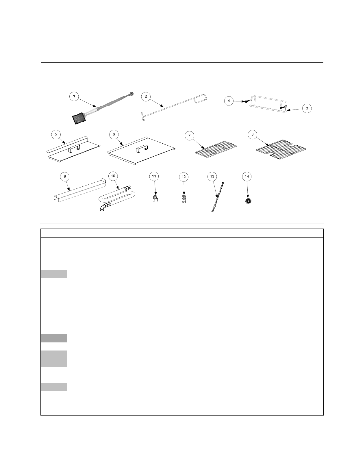
1.1 Accessories
BIGLA30 SERIES LOV™ GAS FRYERS
CHAPTER 1: PARTS LIST
ITEM PART # COMPONENT
1 8030430 Brush, Frypot Ecolab
2 8030388 Fryers Friend LOV™
3 8102793 Hanger, Basket
4 8090171
8090402 Thumbscrew, ¼ -20 X ½-inch Cap-N-Splash Hood
5 1068931 Cover, Frypot, Dual Vat
6 1068930 Cover, Frypot, Full Vat
* 8260993SP Handle Kit, Frypot Cover (includes handle and screws)
7 8030372 Basket Support Rack, Dual Vat
8 8030375 Basket Support Rack, Full Vat
* 8030136 Basket Support Screen, Full Vat (screen w/handle used in place of Item 8)
9 2302975
1086156SP
10 8100478 Gas Line, 1-Inch Dormont Flexible
8061698SP 36-Inch (for gas line only (w/o Items 11 and 12), use 8100088)
8061699 48-Inch (for gas line only (w/o Items 11 and 12), use 8100085)
11 8100074 Quick-Disconnect Fitting, 1-Inch Male
12 8100073 Quick-Disconnect Fitting, 1-Inch Female
8103745 Quick Disconnect Fittings, ¾-inch set (includes male and female connectors)
13 8260900 Kit, Chain Restraint
14 8261045 Bushing, Flexible Gas Line (8130032)
* 8261157 Kit, Fuse and Fuse Puller (2 Fuses)
* Not illustrated.
Thumbscrew, ¼-20 X 1⅜-inch Universal Hood (use 8090921 for Spacer)
Connecting Strip, Frypot prior to 07/2014
Connecting Strip, Frypot after 06/2014
1-1
Page 6
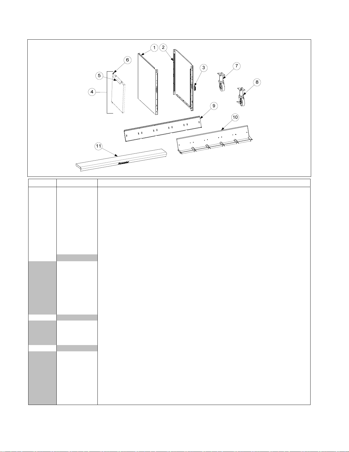
1.2 Doors, Sides, Flue Caps, Cap-N-Splash, Top Caps and Casters
ITEM PART # COMPONENT
1 2317908 Side, Standard Cabinet Left SS (use 2210323 for Enameled Steel)
2 2327908 Side, Standard Cabinet Right SS (use 2220323 for Enameled Steel)
3 8101105 Magnet, Door (vertical) (use 8102346 for horizontal over filter pan)
4 1064397 Door, Left or Right (move handle to bottom for right) (use 1080915 for Door w/ Manual Holder)
5 2304960 Handle, Eurolook Door
6 1064067SP Pin Assembly, Door
* 8100275 Spring, Door Pin
* 8090970 Retaining Ring
* 2307192 Hinge, Door Lower
7 8100327 Caster without Brake
8 8100944 Caster with Brake
9
8237656
8238926
8237657
8238927
8237658
8238928
8238064
8238930
Flue Cap-Stainless Steel (Use Aluminized steel with Cap-N-Splash)
Two Station (8236666 for Alz Steel)(Use 2302635 for Hood Strip) prior to 07/2014
Two Station(8239031 for Alz Steel)(Use 2302635 for Hood Strip) after 06/2014
Three Station (8236681 for Alz Steel) (Use 2302405 for Hood Strip) prior to 07/2014
Three Station (8239032 for Alz Steel)(Use 2302405 for Hood Strip) after 06/2014
Four Station (8236680 for Alz Steel) (Use 2302636 for Hood Strip) prior to 07/2014
Four Station (8239033 for Alz Steel)(Use 2302636 for Hood Strip) after 06/2014
Five Station (8238100 for Alz Steel) (Use 2302637 for Hood Strip) prior to 07/2014
Five Station(8239034 for Alz Steel)(Use 2302637 for Hood Strip) after 06/2014
10 Cap-N-Splash Assemblies
8237659 Two Station Fryer
8237660 Three Station Fryer
8237661 Four Station Fryer
8238101 Five Station Fryer
11 Top Cap (Cap for 5-staion fryer shown)
1081522
1086158SP
1081523
1086159SP
1081524
1086160SP
1083030
1086161
Two Station Fryer prior to 07/2014
Two Station Fryer after 06/2014
Three Station Fryer prior to 07/2014
Three Station Fryer after 06/2014
Four Station Fryer prior to 07/2014
Four Station Fryer after 06/2014
Five Station Fryer prior to 07/2014
Five Station Fryer after 06/2014
* Not illustrated.
1-2
Page 7
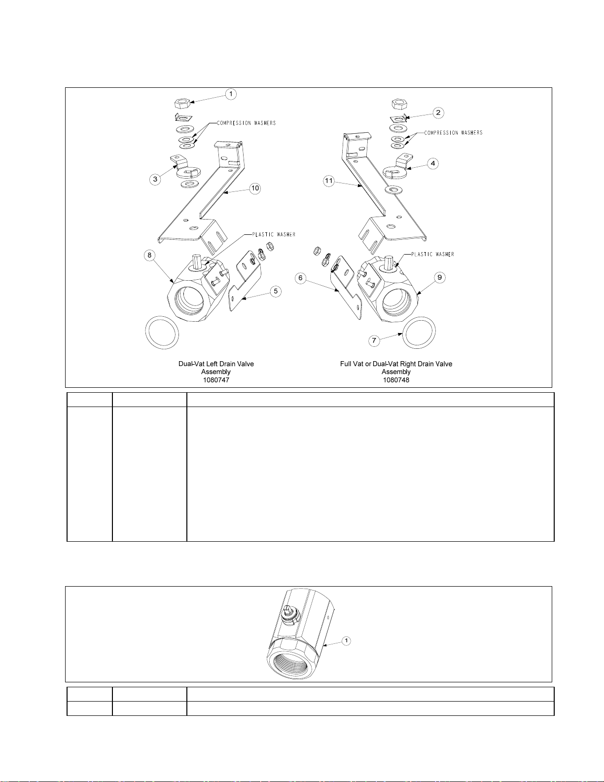
1.3 Drain Valves and Associated Parts
1.3.1 Linear Actuator Drain Valves
ITEM PART # COMPONENT
1 8090540 Nut, ½-13 2-Way Hex Lock
2 9002936 Retainer, Nut Drain Valve
3 2316294 Handle, Drain Valve DV Left
4 2326294 Handle, Drain Valve FV or DV Right
5 2216306 Bracket, Drain Valve Lt.
6 2226306 Bracket, Drain Valve Rt.
7 8160544 O-Ring, Round Drain Seal
8 8237230
9 8237231
Valve, 1¼-inch Drain Lt. (02/2010-04/2012)
Valve, 1¼-inch Drain Rt. (02/2010-04/2012)
10 8242146 Mount, Stud Drain Actuator Gas Lt.
11 8242147 Mount, Stud Drain Actuator Gas Rt.
1.3.2 Rotary Actuator Drain Valves
ITEM PART # COMPONENT
1 8103755
Valve, 1¼-inch NPT Rotary Actuator
(05/2012 – Present)
1-3
Page 8
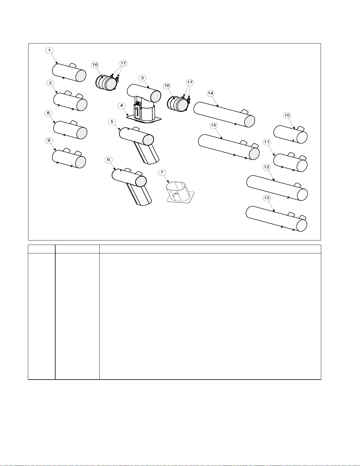
1.4 Drain Tube Sections and Associated Parts
See Section 1.3 for Drain Valves
ITEM PART # COMPONENT
1 8237323 Drain Tube, Full-Vat Left Closed/Right End Open
2 8237325 Drain Tube, Dual-Vat Left Closed/Right End Open
3 1080887SP Drain Tube, Dump
4 8237468 Shroud, Filter Pan Lid (attaches to item # 3)
5 1081118SP Drain Tube, Full-Vat 2 Bat. Dump Left Closed/Right End Open
6 1081120 Drain Tube, Dual-Vat 2 Bat. Dump Left Closed/Right End Open
7 8237480 Shroud, Filter Pan Lid 2 Bat. (attaches to item # 5 and 6)
8 8237322 Drain Tube, Full-Vat Left and Right Open
9 8237324 Drain Tube, Dual-Vat Left and Right Open
10 8237330 Drain Tube, Full-Vat 2 Bat. Left Open/Right End Closed
11 8237331 Drain Tube, Dual-Vat 2 Bat. Left Open/Right End Closed
12 8237329 Drain Tube, Full-Vat Left Open/Right End Closed
13 8237326 Drain Tube, Dual-Vat Left Open/Right End Closed
14 8237328 Drain Tube, Full-Vat Left and Right Open
15 8237327 Drain Tube, Dual-Vat Left and Right Open
16 8160772 Sleeve
17 8090969 Clamp
* 8160630 Vinyl Cap
* Not illustrated.
1-4
Page 9
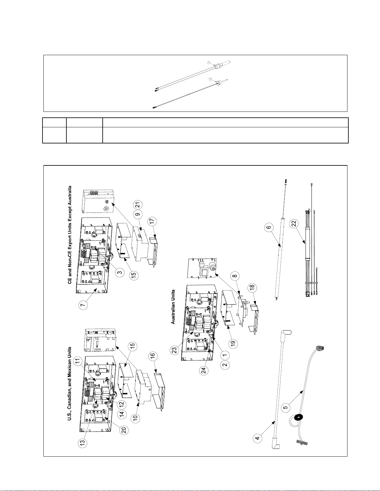
1.5 Electronics and Electrical Components
1.5.1 High-Limit Thermostat and Temperature Probe
ITEM PART # COMPONENT
√ 1 8261177
√ 2 8262900
√ Recommended parts.
Thermostat Assembly, HE FM High-Limit 425F/218C
Temperature Probe, LOV™
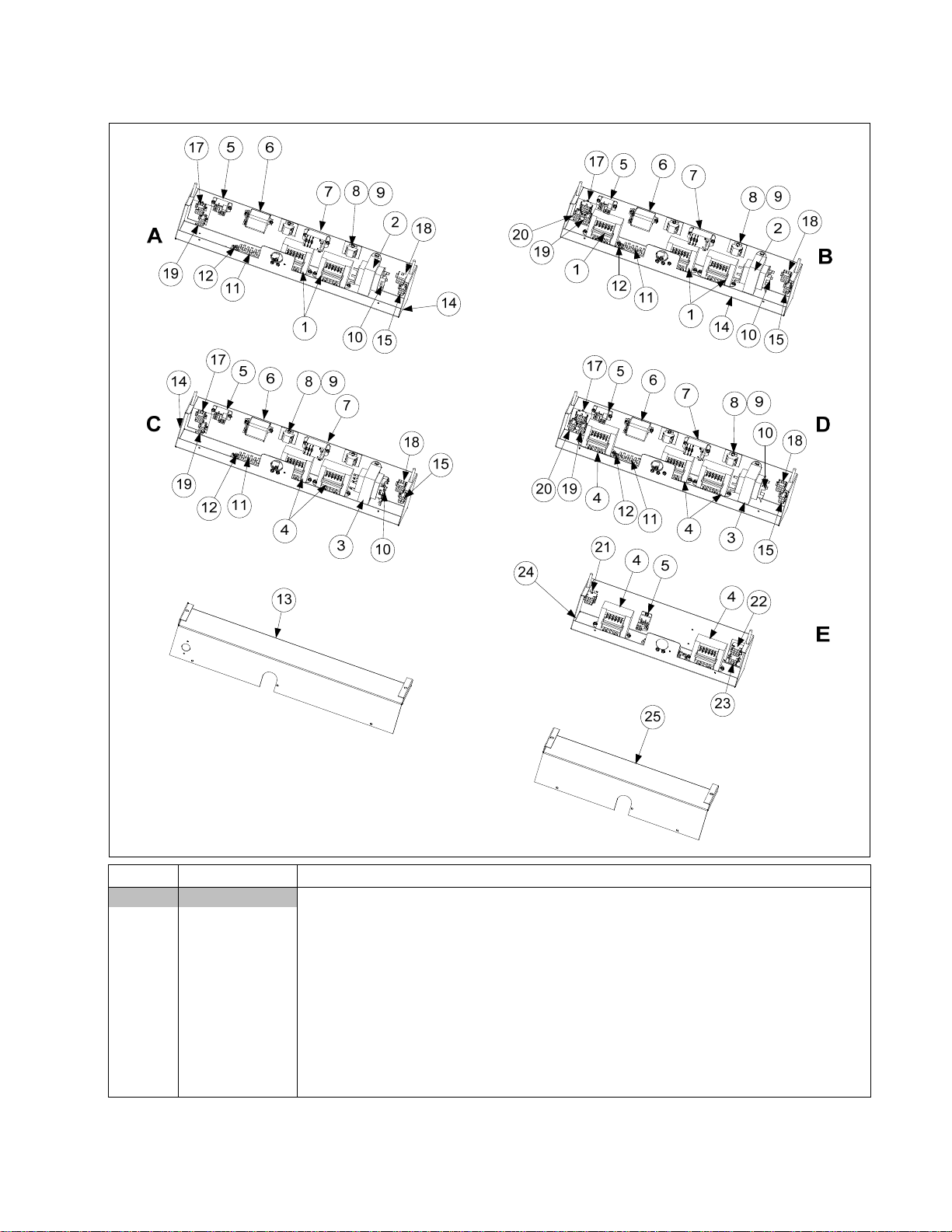
1.5.2 Component Boxes
1-5
Page 10

1.5.2 Component Boxes cont.
ITEM PART # COMPONENT
1 8101164 Block, One-Piece Screwless Terminal
2 8160217 Insulation, Terminal Block Paper
3 8073843 Fuse 3A 250V Domestic
√
8073293
4 8075008 Cable, 21-inch Ignition – For 8073366/8073365 Modules
√
* 8075009 Cable, Ignition 19” (CE)
* 8075266 Cable, Ignition, Australian units
* 8073484 Connector, Rajah
5 8074199 Cable, 20-pin Computer to 15-pin Interface Board - SMT
6 8066085SP Wire Assembly, Ignitor
7 2206102 Box, One-Piece Component
8 8072971 Ignition Module, (Australia)
√
9 8071006 Ignition Module, CE Honeywell
√
10 8075691~ Ignition Module Capable Controls Single-Spark Full-Vat and Dual-Vat CE/Non-CE
√
8073366† Ignition Module, Honeywell Dual-Spark Full-Vat (Domestic and Non-CE export unit
√
8073365† Ignition Module, Honeywell Single-Spark Dual-Vat (Domestic and Non-CE export
√
11 8262264 Interface Board Kit SMT
√
8074330 Speaker Adapter Harness SMT
8074343 Wire Harness, SMT Interface Board to Ignition Module
12 8070833
√
13 8070834
√
14 8102243 Spring, Relay Retaining
15 1081094 Plate, Ignition Module
16 8242090 Cover, Ignition Module
17 8242091 Cover, Ignition Module CE
18 2207085 Cover, Ignition Module Australia
19 1081544 Plate, Ignition Module Australia
20 8074812
8074934
21 1060531SP Fuse Assembly, Inline (not used on all models)
* 8072659 Switch, Momentary (Control Power Reset, only used in far left component box)
* 8074403 Speaker SMT
22 1081260SP Wire Assembly, Ignition Module Domestic and Non-CE export, except Australia.
1082353 Wire Assembly, Ignition Module CE
23 8064973 Interface Board – Australia Only
24 8071683 Relay, 12VDC Reset Switch
* Not illustrated.
√ Recommended parts.
~ For Full-vat or Dual-vat units, use two 8075691 Single Spark Ignition Modules (see NOTE 1).
† For Full-vat units, use one 8073366 Honeywell Dual Spark Ignition Module (see NOTE 3).
† For Dual-vat units, use two 8073365 Honeywell Single Spark Ignition Modules (see NOTE 3).
NOTE 1: Fryers using 8075691 Single-Spark Capable Controls modules use two modules for both Full-Vat and DualVat Fryers. Also, in full-vat units, only two latch relays (Item 12) are used, located in the sockets on the right side of
the interface board. These relays are located in the bottom sockets of the interface board and control the heating
circuit.
NOTE 2: The relays in the top sockets control the oil level sensors.
NOTE 3: Domestic U.S. and Non-CE Export except Australia units use two different modules depending upon the
configuration of the frypot. Full-Vat units use one 8073366 Dual-Spark Ignition Module while Dual-Vat units use two
8073365 Single-Spark Ignition Modules. Also, in full-vat units, only two latch relays (Item 12) are used, located in the
sockets on the right side of the interface board. These relays are located in the bottom sockets of the interface board
and control the heating circuit.
Fuse 5A 125V International Only
except Australia)
unit except Australia)
Relay, DPDT 5A 12VDC Latch (See NOTE 1.)
Relay, SPDT 15A 12VDC Oil Level Sensor (See NOTE 2.)
Relay, 7-second Time Delay 120V (U.S., Canadian and Mexico units)
Relay, 7-second Time Delay 220V, 230V, 240V and 250V units (International units)
1-6
Page 11
1.5.3 Transformer Boxes
ITEM PART # COMPONENT
Box Assembly, Transformer
A 1068135SP GL230 and 430 (430 has added cordset 1080871)
B 1068122SP GL330
C 1069734 GL230 and 430 CE Export (430 has added cordset 1080871) (1069750 430 CE Ex-
port with 1080871)
D 1069710SP GL330 CE Export
E 1081423 GL 430 CE Export
1 8072176 Transformer, 100-120V V/F Dual Voltage
√
2 8072181 Transformer, 100-120V/24V 62VA Filter and MIB
√
3 8072180 Transformer, 100-120VV/24V 50VA Filter and MIB
√
4 8071999 Transformer, V&F Dual Voltage 208/222/230/240V
√ Recommended parts.
1-7
Page 12
1.5.3 Transformer Boxes cont.
ITEM PART # COMPONENT
5 8071683 Relay, Hood 12V DC
√
6 8074346 Relay, DPDT 20A 120VAC (Control Reset Button) (used for control power reset in
√
domestic units)
8074770 Relay, DPDT 20A 240V (used for control power reset in international units)
√
7 8074482 Relay, Filter 30A 24VDC DPDT
√
8 8160217 Insulation, Terminal Block Paper
9 8101164 Block, One-Piece Screwless Terminal
10 8071597 Fuse, 3amp Slo-Blow
√
11 8071973 Terminal, Post
12 8070070 Terminal, Ground Lug
13 2203191 Cover, Large Transformer Box
14 8236324 Box, Large Transformer/Filter
15 1068133SP Cable Assembly, Transformer Box Line GL230, 330, 430, 230 and 330 CE Export
and 430 CE Export
16 1068168 Cable Assembly, Transformer Box Line GL230 CE Export
17 1068170 Cable Assembly, Transformer Box Filter Pump GL230, 330, 230 and 330 CE Export
18 1080994SP Cable Assembly, Transformer Box #1 GL230,330, 230 and 330 CE Export
19 1080995SP Cable Assembly, Transformer Box #2 GL230, 330, 230 and 330 CE Export
20 1080996SP Cable Assembly, Transformer Box #3 GL330 and 330 CE Export
21 8068706 Plug Assembly, LT #252
22 8068707 Plug Assembly, RT #252
23 1066996 Harness Assembly, Cord set Female McD
24 8237400 Box, Transformer/Filter GL30 4-Battery
25 2206514 Cover, GL30 4-Battery Transformer Box
* WIR 0100 Wire Assembly, GL 430 McD Double (used in Item E)
* WIR 0623 Wire Assembly, GL230/430 Hood Relay (used in Item A, B, C and D)
* WIR 0798 Wire Assembly, GL330 Transformer/Filter Box (used in Item B, C and D)
* WIR 0799 Wire Assembly, GL230/430 Transformer/Filter Box (used in Item A)
* Not illustrated
√ Recommended parts.
1.5.4 Computers and Associated Components
NOTE: See Page 1-5 for Interface Board to Computer Wiring Harness.
ITEM PART # COMPONENT
Computer, McDonald’s M3000 Gas Fryer SMT
√ 1081284SP
√ 1081282
√ 1082969
√ 1081290
Non-CE M3000 (For use in US, Canada, Mexico and other non-CE countries)
CE M3000 (For use in European CE countries)
M3000 (For use in Russia only)
M3000 (Australia Only)
* 8074403 M3000 Speaker SMT
* Not illustrated.
√ Recommended parts.
1-8
Page 13

1.6 Wiring
1.6.1 Main Wiring Harnesses
2-PIN FEMALE
CONNECTOR
12-PIN MALE
CONNECTOR
12-PIN MALE
CONNECTOR
2-PIN FEMALE
CONNECTOR
807-1978
9-PIN MALE
CONNECTOR
12-PIN MALE
CONNECTOR
807-4014
12-PIN MALE
CONNECTOR
ITEM PART # COMPONENT
8071978 Main Wiring Harness Vat 1 (Far left controller) (9-pin)
8074014 Main Wiring Harness Vat 2, 3, 4 and 5 (6-pin)
1-9
6-PIN MALE
CONNECTOR
Page 14

1.6.2 Miscellaneous Wiring
ITEM PART # COMPONENT
1 8074316 Power Cord, 120V w/Grounding Plug 5 wire (w/Ring Terminals, no Clamp)
2 8074317 Power Cord, CE
8075225 Power Cord, 3-Wire 15A, 250V (Korea)
3 8069678SP Plug Assembly, CE Gas Valve
1.6.3 M3000, MIB, AIF and ATO Wiring Harnesses (Refer to wiring diagram on page 1-60 in the
BIGLA30 LOV Service Manual.)
ITEM PART # COMPONENT
* 8074546 Computer Communication (used from Computer to Computer)
* 8074547 AIF Communication/Power (used from AIF to AIF and AIF to ATO)
* 8074850 Communication/Power (used from MIB to AIF)
* 8074562
* 8074655 FV/DV Harness RTD Extension 20” (used from RTD to ATO Board)
* 8074845 FV/DV Harness RTD Extension 28” (used from RTD to ATO Board)
* 8262569 FV/DV ATO/RTD Probe Kit
* 8074621 FV/DV Harness RTD Short (used from RTD to ATO Board)
* 8074771 ATO Power (used from Transformer to ATO Board)
* 8074555 ATO Yellow LED (used from ATO Board to Yellow LED)
* 8074573
* 8074552
* 1068977SP Long Top-off Power (used between Transformer Box to ATO Box) Domestic
* 1081589SP Long Top-off Power (used between Transformer Box to ATO Box) CE and Export
* 1069544 ATO Power to Secondary ATO box (4 and 5 battery only)
* 8074671
√ * 8074660PK SMT Pin Service Repair Kit
√ * 2302345 SMT Pin Extractor
* Not illustrated.
√ Recommended parts.
See page 1-27, 1-32, 1-39 and 1-50 in the BIGLA30 Service Manual for Pin Positions.
MIB Power/Blue LED/Pan Sw (used from Transformer and Fltr Rly to MIB to Blue
LED and Pan Sw)
Computer Locator Wire (used from Computer to Interface Board) See wiring dia-
gram 805-1725 for locator pin positions.
Communications Terminator (used on Computer pin J6 and ATO board pin J10 to
terminate network)
Harness, LOV™ RTI-MIB connector
1-10
Page 15

1.7 Frypots and Associated Components
1.7.1 Full-Vat Frypot Components
NOTE: All insulation and
gaskets can be ordered in
a single kit, P/N 826-2595.
Kit 826-2592 contains the
insulation and gaskets re-
quired when replacing
burners.
1-11
Page 16

1.7.1 Full-Vat Frypot Components cont.
ITEM PART # COMPONENT
1080858SP
1081752SP
8262595 Insulation Kit, Complete Full-Vat
8262592 Insulation Kit, Burner Full-Vat
1 1080925SP Flue Assembly, Full-Vat
2 2206470 Back, Lower Full-Vat Combustion Chamber
3 2206529 Retainer, Full-Vat Upper Insulation
4 2206664 Retainer, Outer Frypot
5 2306960 Plate, FV Collector Mounting
6 2202851 Brace, FV Rear Insulation
7 2202920 Brace, Foam Deck Insulation
√ 8 8103435 Burner, Universal Replacement LOV™
9 8120356 Insulation, Burner Sight Glass
10 8160900 Insulation, Burner
11 8120706 Insulation, Upper Burner Rail
12 8121029 Insulation, Combustion Chamber Side
13 8140048SP Glass, Burner Sight
14 8160837 Insulation, FV Rear Lower
15 8160731 Insulation, FV LH/RH Front Seal
16 8160976
17 8160733 Insulation, FV Front Upper
18 8160978
19 8160746 Insulation, Foam Deck
20 8237283
8238932
21 8238193 Retainer, FV LH Upper Burner
22 8238194 Retainer, FV RH Upper Burner
23 8238577 Retainer, FV Front Insulation
24 8238575 Retainer, FV Outer Front
25 8242164 Front Upper Seal Weldment, FV LH
26 8242165 Front Upper Seal Weldment, FV RH
27 9001031 Retainer, Burner Sight Glass
28 9300818 Bracket, Flue to Pot
29 9004253 Strip, Fluecap Retainer
30 9001049 Retainer, Plenum Gasket
31 8160057 Gasket, Plenum
32 8238574
* 8160059 Gasket, Ignitor
* 9102474 Pot-to-Pot Gap Clip
* Not illustrated.
√ Recommended parts.
Frypot Assembly Full-Vat LOV™ HE (NAT/PRO) prior to 07/2014
Frypot Assembly Full-Vat LOV™ HE (NAT/PRO) after 06/2014
Insulation, FV Lower Inner Front (may require 8238577 for serial #’s after 1209)
Insulation, FV Outer Front (may require 8238575 for serial #’s after 1209)
Frypot, FV LOV™ 30 439 SS prior to 07/2014
Frypot, FV LOV™ 30 439 SS ) after 06/2014
Plenum, Full-Vat LOV™ (use 8238590 for CE and Export Non-CE units)
1-12
Page 17

1.7.2 Dual-Vat Frypot Components
NOTE: All insulation and
gaskets can be ordered
in a single kit, P/N 826-
2596. Kit 826-2593 contains the
insulation and gaskets
required when replacing
burners.
1-13
Page 18

1.7.2 Dual-Vat Frypot Components cont.
ITEM PART # COMPONENT
* 1080860SP
* 1081753SP
* 8262596 Insulation Kit, Complete Dual-Vat
* 8262593 Insulation Kit, Burner Dual-Vat
1 1080926SP Flue Assembly, Dual-Vat
2 1067960 Plate Assembly, Dual-Vat Collector
3 2206530 Retainer, Dual-Vat Upper Insulation
4 2206665 Retainer, Dual-Vat Outer Frypot
5 2206180 Back, Dual-Vat Lower Combustion Chamber
6 2202920 Brace, Foam Deck Insulation
7 2202972 Brace, Dual-Vat Rear Insulation
√ 8 8103435 Burner, Universal Replacement
9 8120356 Insulation, Burner Sight Glass
10 8160900 Insulation, Burner
11 8120706 Insulation, Upper Burner Rail
12 8121029 Insulation, Combustion Chamber Side
13 8140048SP Glass, Burner Sight
14 8160838 Insulation, Dual-Vat Rear Lower
15 8160741 Insulation, Dual-Vat LH/RH Front Seal
16 8160977
17 8160743 Insulation, Dual-Vat Front Upper
18 8160979
19 8160746 Insulation, Foam Deck
20 8120688 Insulation, Flue Collection
21 8238196 Retainer, Dual-Vat RH Upper Burner
22 8238195 Retainer, Dual-Vat LH Upper Burner
23 8238578 Retainer, Dual-Vat Front Insulation
24 8238576 Retainer, Dual-Vat Outer Front
25 8241796 Riser W/A Dual-Vat Pot
26 8242166 Dual-Vat LH Upper W/A Seal
27 8242167 Dual-Vat RH Upper W/A Seal
28 9001031 Retainer, Sight Glass
29 9300818 Bracket, Flue to Pot
30 9004253 Strip, Fluecap Retainer
31 9001049 Retainer, Plenum Gasket
32 8160057 Gasket, Plenum
* 8160059 Gasket, Ignitor
33 8238573
34 8237288
8238942
* 9102474 Pot-to-Pot Gap Clip
* Not illustrated.
√ Recommended parts.
Frypot Assembly Dual-Vat w/RF HE (NAT/PRO) prior to 07/2014
Frypot Assembly Dual-Vat w/RF HE (NAT/PRO) after 06/2014
Insulation, Dual-Vat Lower Inner Front (may require 8238578 for serial #’s after
1209)
Insulation, Dual-Vat Outer Front (may require 8238576 for serial #’s after 1209)
Plenum, Dual-Vat LOV™ (use 8238589 for CE units and Export Non-CE units)
Frypot, Dual-Vat LOV™ 30 439 SS prior to 07/2014
Frypot, Dual-Vat LOV™ 30 439 SS after 06/2014
1-14
Page 19

1.7.3 Frypot Assemblies and Associated Parts
1.7.3.1 Frypots with Linear Actuators (02/2010-04/2012)
See Page 1-21 for
Return Valve
Full Vat Dual Vat
Assemblies.
ITEM PART # COMPONENT
1 1080858SP Frypot Assembly, Full-Vat LOV™ Natural/Propane
2 1080860SP Frypot Assembly, Dual-Vat LOV™ Natural/Propane
√ 3 8262587 Actuator, Linear AIF 24VDC Kit (includes 8101776)
√ 4 8091012 Pin, Clevis, ¼ x 1¼
√ 5 8091036 Pin, Clevis, ¼ x 2
√ 6 8101776 Cotter Pin, Toaster Ring
7
8
9
10
11
12
13
√ 14 8262706 Probe, RTD AIF/ATO Kit
√ 15 8074817 Probe, Temperature Cooking
√ 16 8074815 Sensor Assy, Oil 120V
√ 17
18 2206472 Bracket, Rear AIF Mounting
19 2203183 Brace, DV AIF Support
20 2206666 Bracket, Actuator Support
21 2205299 Bracket, Front AIF Mounting
√ Recommended parts.
1080748SP
1080747SP
1080750SP
1080749SP
8130165
8101668
8101055
8074947
8074935
8074942
8261177
Valve, Drain Assy. LOV™ AIF FV or DV Right viewed front of frypot. (02/10-04/12)
Valve, Drain Assy LOV™ AIF DV Left as viewed front of frypot. (02/10-04/12)
Valve, Return Assy LOV™ AIF FV or DV Right viewed from front of frypot. (02/10-
04/12)
Valve, Return Assy LOV™ AIF DV Left as viewed from front of frypot. (02/10-04/12)
Elbow, Street ½” x ½” NPT 90 BM
Adaptor, Male ⅝” OD x ½”
Flexline, ⅝” OD x 11.50” Long
Sensor Assy, Oil 220V International
Sensor Assy, Oil 230V International
Sensor Assy, Oil 240V and 250V International
Thermostat Assembly, HE High-Limit 425F/218C Standard
See Page 1-3
for Drain Valve
Assemblies.
1-15
Page 20

1.7.3.2 Frypots with Rotary Actuators (05/2012-Present)
Full Vat Dual Vat
ITEM PART # COMPONENT
1 1081752SP Frypot Assembly, Full-Vat LOV™ Natural/Propane
2 1081753SP Frypot Assembly, Dual-Vat LOV™ Natural/Propane
√ 3
√
4
√
5
√
6
7
8
9
√ 10 8262706 Probe, RTD AIF/ATO Kit
√ 11 8263196 Probe, Temperature Kit
√ 12 8074815 Sensor Assy, Oil 120V
√ 13
√ Recommended parts.
8074961
8074962
8104353
8103754
8130165
8101668
8101055
8074947
8074935
8074942
8261177
Actuator, Rotary 24VDC (#1) Blue (05/2012-Present)
Actuator, Rotary 24VDC (#2) Black (05/2012-Present)
Valve, 1¼ Drain Rotary Actuator LOV™ (05/2012-Present)
Valve, ½ NPT Return Rotary Actuator LOV™ (05/2012-Present)
Elbow, Street ½” x ½” NPT 90 BM
Adaptor, Male ⅝” OD x ½”
Flexline, ⅝” OD x 11.50” Long
Sensor Assy, Oil 220V International
Sensor Assy, Oil 230V International
Sensor Assy, Oil 240V and 250V International
Thermostat Assembly, HE High-Limit 425F/218C Standard
1-16
Page 21

1.8 Oil Return Manifolds
ITEM PART # COMPONENT
1 8103275 Manifold, Two-Station Fryer
2 8103245 Manifold, Three-Station Fryer
3 8103368 Manifold, Four-Station Fryer
* 8130907 Cap, 15/16-inch Valve
* Not illustrated
1.9 Return Valves and Associated Parts
1.9.1 Return Valves and Associated Parts (Linear Actuators) (02/2010-04/2012)
Dual-Vat
Left Return Valve
Assy.
1080749SP
ITEM PART # COMPONENT
1 2316295 Handle, Return Valve Gas LOV™ DV Left
2 2326295 Handle, Return Valve Gas LOV™ FV or DV Right
3 2306011 Brace, Gas Return Actuator Bracket
4 8102201
Valve, ½-inch Ball
(02/2010-04/2012)
5 8237273 Mount, Gas Return Actuator LH
6 8237274 Mount, Gas Return Actuator RH
7 9002935 Retainer, Nut Oil Return Valve
1.9.2 Return Valve (Rotary Actuators) (05/2012-Present)
Full-Vat or DualVat Right ReturnValve Assy.
1080750SP
Full-Vat or Dual-
1
Vat Return Valve
ITEM PART # COMPONENT
1 8103754
Valve, ½-inch NPT Rotary Actuator (05/2012-Present)
1-17
Page 22

1.10 Gas Supply and Combustion System Components
See pages 1-13 through 1-15
for burners and burner insulation part numbers.
1-18
See Page 1-20 – 1-21 for details of gas
valves and related components.
Page 23

1.10 Gas Supply and Combustion System Components cont.
ITEM PART # COMPONENT
√ 1 Ignitor
8263054 Natural Gas (G20, G25) (includes gasket 8160981, which may be ordered sepa-
rately)
8262994 Propane (G30, G31) (includes gasket 8160981, which may be ordered separately)
√ 2 Blower Assembly, Combustion Air (includes harness and Item 3)
1087153SP 115V 50/60 Hz (Right)
1087155 220V 60 Hz (Right)
1062998SP 208-240V 50/60 Hz (Right) Non-CE International
1082360SP 230V 50Hz CE FV Australia
1082361SP 230V 50Hz (Right) CE DV Australia
1063001SP 230V 50/60 Hz CE (Right) CE (Wide Body)
3 8160554 Cover, Blower Motor (component of most blowers listed above)
* 8068806SP Harness Assembly, Blower Motor (component of all blowers listed above)
4 Orifice, Burner
8103977 1.88mm 75% Butane/25% Butane (Standard Elevation)
** 8103865 1.95mm Propane/Butane (G30, G31) Australia Only
** 8103860 2.05 mm Propane/Butane (G30, G31) (0-4999 Ft, 0-1524 M)
** 8103863 2.10 mm Propane/Butane (G30, G31) (5000-6999 Ft, 1525-2133 M)
** 8103867 2.84mm Natural Gas (G20, G25) Australia Only DV
** 8103866 2.92mm Natural Gas (G20, G25) Australia Only FV
** 8103864 3.18 mm Natural Gas (G20, G25) (0-4999 Ft, 0-1524 M) CE, Non-CE
** 8103861 3.26 mm Natural Gas (G20, G25) (0-4999 Ft, 0-1524 M)
** 8103862 3.40 mm Natural Gas (G20, G25) (5000-6999 Ft, 1525-2133 M)
** 8262965 Conversion Kit, Natural Gas FV (G20, G25) to Propane/Butane(G30,G31) Non-CE
** 8262966 Conversion Kit, Natural Gas DV (G20, G25) to Propane/Butane(G30,G31) Non-CE
** 8262967 Conversion Kit, Propane/Butane FV(G30, G31) to Natural Gas (G20,G25) Non-CE
** 8262968 Conversion Kit, Propane/Butane DV(G30, G31) to Natural Gas (G20,G25) Non-CE
** 8262969 Conversion Kit, Nat Gas FV (G20, G25) to Prop/Butane(G30,G31) Aust Non-CE
** 8262970 Conversion Kit, Nat Gas DV (G20, G25) to Prop/Butane(G30,G31) Aust Non-CE
** 8262971 Conversion Kit, Prop/But FV(G30, G31) to Natural Gas (G20,G25) Aust Non-CE
** 8262972 Conversion Kit, Prop/But DV(G30, G31) to Natural Gas (G20,G25) Aust Non-CE
** 8262975 Conversion Kit, Nat Gas (G20, G25) to Prop/Butane(G30,G31) CE
** 8262976 Conversion Kit, Prop/But (G30, G31) to Natural Gas (G20,G25) CE
√ 5 1081455SP Switch, Air Pressure Assembly DV (8122141 switch alone)
√ 1083346 Switch, Air Pressure Assembly FV (8122226 switch alone)
* Not illustrated.
√ Recommended parts.
8121138 1.85 mm Propane/Butane (G30, G31) (0-4999 Ft, 0-1524 M) (CE)
8121137 1.95mm Propane/Butane (G30, G31) Australia Only
8100416 2.05 mm Propane/Butane (G30, G31) (0-4999 Ft, 0-1524 M)
8100386 2.10 mm Propane/Butane (G30, G31) (5000-6999 Ft, 1525-2133 M)
8121135 2.15 mm Propane/Butane (G30, G31) (7000-10,999 Ft, 2134-3352 M)
8103840 2.84mm Natural Gas (G20, G25) Australia Only DV
8103839 2.92mm Natural Gas (G20, G25) Australia Only FV
8103740 3.18 mm Natural Gas (G20, G25) (0-4999 Ft, 0-1524 M) CE
8103269 3.26 mm Natural Gas (G20, G25) (0-4999 Ft, 0-1524 M)
8100403 3.40 mm Natural Gas (G20, G25) (5000-6999 Ft, 1525-2133 M)
8120909 3.45 mm Natural Gas (G20, G25) (7000-8999 Ft, 2134-2743 M)
8121133 3.50 mm Natural Gas (G20, G25) (9000-10,999 Ft, 2744-3352 M)
**For fryers manufactured OCT 2010 and after. NPT Threads
For fryers manufactured prior to OCT 2010
1-19
Page 24

1.11 Gas Valves and Associated Components
1-20
Page 25

1.11 Gas Valves and Associated Components cont.
ITEM PART # COMPONENT
√ 1 Valve, Non-CE Gas
8261122 Natural Gas (G20, G25)
8261120 Kit Natural Gas w/ flexlines and hardware
8261123 Propane Gas (G30, G31)
8261121 Kit, Propane Gas w/ flexlines and hardware
√ 2 8101715 Valve, CE Gas (G20, G25, G30, G31)
3 8101041 Accessory Kit (contains parts to adapt Item 2 to specific fryer configuration)
4 8100691
Tube, ⅛-inch Vent
5 8100494 Ferrule (Nut), Orifice
6 8101355
7 8101354
8101353
8 8110800
* 8103807
9 8130301
10 8130302
Gas Line, ⅜-inch OD X 15-inch SS Flexible
Gas Line, ⅜-inch OD X 12-inch SS Flexible
Gas Line, ⅜-inch OD X 9-inch SS Flexible (Used on some split pots)
Tube, ⅛-inch OD X 12.5-inch Enrichment (cut and form to fit)
Tube, ⅛-inch OD X 6.5-inch Enrichment (Used after Oct 2010)
Tee, ¼-inch Male NPT to ⅜-inch Tube
Elbow, ¼-inch Male NPT to ⅜-inch Tube 90° (used on DV valve)
11 8130304 Bushing, ½-inch NPT to ¼-inch NPT Flush Reducing
12 8130405
13 8130378
14 8130340
15 8130154
16 8101176
17 8130377
18 8130354
19 8130016
20 8101006
Nipple, ⅛-inch NPT X 2-inch
Fitting, ⅛-inch NPT Cross
Adapter, ⅛-inch NPT to ⅛-inch Tube
Plug, ⅛-inch NPT Hex Head Pipe
Tap, ⅛-inch NPT Pressure
Tee, ⅛-inch NPT Female
Elbow, ⅛-inch NPT X ⅛-inch Tube Compression
Nipple, ⅛-inch NPT X Close
Bushing, ¼-inch NPT to ⅛-inch NPT Reducing
21 8130495 Tee, ¼-inch Male NPT to Female NPT
22 8101025
Connector, ¼-inch Male NPT to ⅜-inch Tube
23 8101026 Tee, ¼-inch Male NPT to Female NPT Street
24 8130700 Nipple, ¼-inch NPT x 3-inch
25 8103147 Bushing, ¾-inch OD x ½ -inch ID NPT Flush
26 8103807 Tube, FPGL Gas Enrichment
27 8130449 Tee, ¼ -inch NPT Brass
√ Recommended parts.
1-21
Page 26

1.12 Filtration System Components
Pump plumbing may differ somewhat from
illustration depending on configuration and
date of manufacture.
ITEM PART # COMPONENT
1 8237602 Lid, Multi-Vat Fryers, Standard Size Filter Pan
8237502 Lid, Two-Vat Fryer, Half Size Filter Pan
2 8103276 Crumb Tray, Standard Size Filter Pan 3, 4 and 5 Vat
8103288 Crumb Tray, Two-Vat Fryer, Half Size Filter Pan
3 8103268
8103289
4 2002240 SanaGrid Filter Screen, Standard Size Filter Pan
2202901 SanaGrid Filter Screen, Two-Vat Fryer, Half Size Filter Pan
5 1081209SP Pan, One-Piece Filter LOV™ Standard Size (Use 1069148 for French Pan)
1068211SP Pan, Two-Vat Fryer, LOV™ Half Size
√ * 8261392 O-Ring (Pkg. of 5; used with Item 5)
* 8130568
6 8233879 Suction Tube Standard LOV™
8236458 Suction Tube Two Vat LOV™
7 8103007 Magnet, Pull Ring
* Not illustrated. √ Recommended parts
Hold-Down Ring 16.56” x 22.32”, Standard Size Pan (3, 4, and 5 Vat Fryers)
Hold-Down Ring 11.20” x 19.10”, Half Size Filter Pan (2-Vat Fryer)
Plug, ⅛-inch Socket Head Pipe (used with Item 5; two required)
1-22
Page 27

1.12 Filtration System Components cont.
ITEM PART # COMPONENT
8 1082218SP Assembly, Filter Pan Switch 3, 4 and 5 Battery
1080839SP Assembly, Filter Pan Switch 2 Battery
√ * 1065876SP Sensor, Magnet
9 2203879 Rail, Filter Pan Retaining Standard
2314821 Rail, Filter Pan Retaining Two Vat Left (use 2324822 for Right)
9a 2304820 Rail, RH LH Lower Two Vat
10 2207911 Support, Left Filter Pan
2207909 Support, Left Filter Pan Two Vat LOV™
11 2207912 Support, Right Filter Pan
2207910 Support, Right Filter Pan Two Vat LOV™
√ 12 Motor and Gasket Kit
8261785 100V 50/60 Hz
8261712 115V 50/60 Hz
8261756 208V 50/60 Hz
8261270 220-240V 50/60 Hz
8261755 250V 50/60 Hz
√ 13 8263191 Pump and Gasket Kit, 4 GPM
8160093 Gasket, Pump/Motor
* 8091062 Cap Screw, 5/16-inch-18 4.00” NC Hex (Connects pump to motor use 8090194 washers)
14 8130165 Elbow, ST ½-inch x ½-inch NPT 90° BM
15 8101668
Adapter, ⅝-inch to ½-inch NPT Male
16 8101067 Flexline, 8.5-inch Oil Return
17 8101057 Flexline, 13-inch Oil Return
18 8130342 Elbow, Street 45° x ½-inch NPT
19 8130002 Nipple, ½-inch x Close NPT BM
20 8100667 Check Valve ½-inch NPT
21 2206190 Brace, Pump Motor
* 8071105 Heater Strip Assembly, 100-120V 25W 18”
* 8071098 Heater Strip Assembly, 208-250V 25W 18”
* Not illustrated. √ Recommended parts.
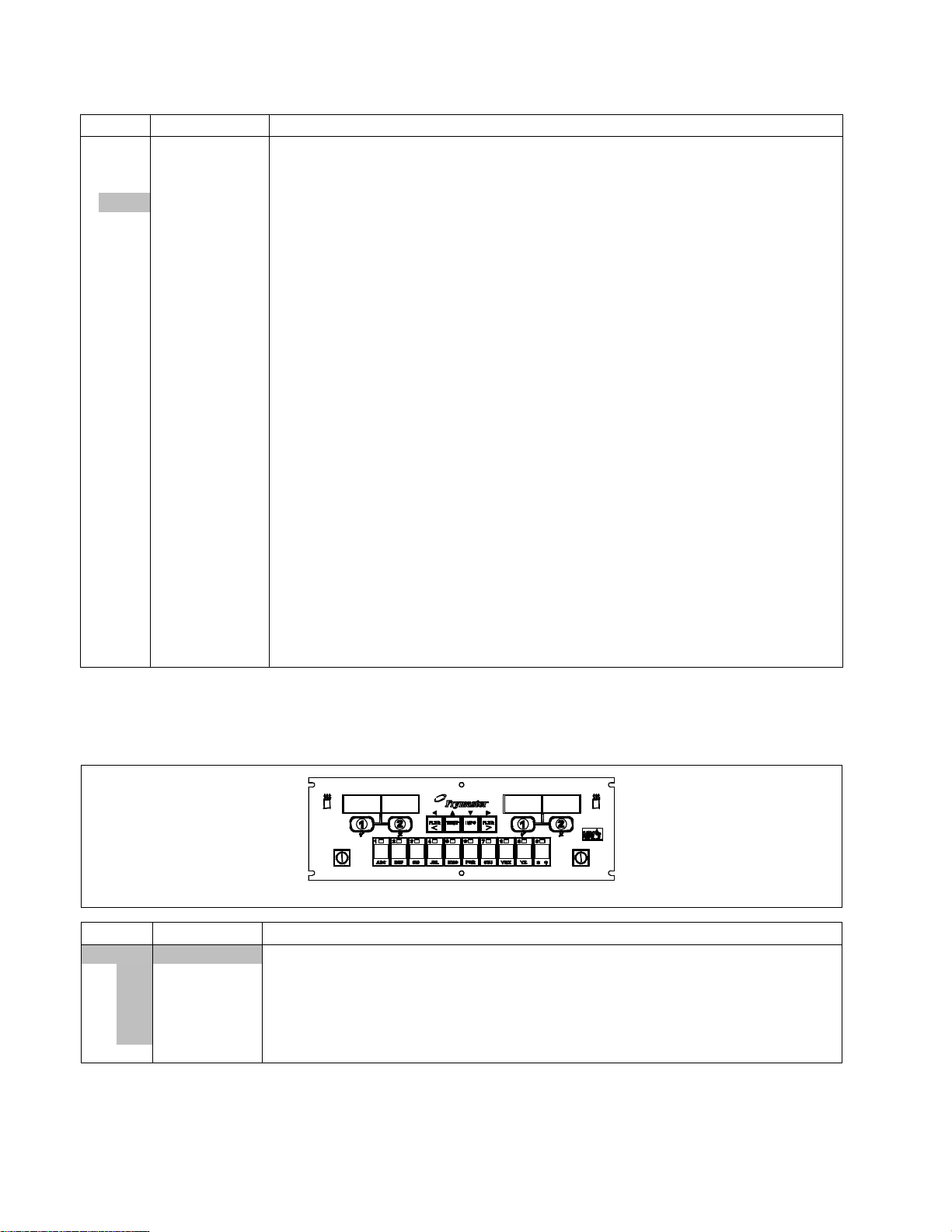
1.13 Auto Intermittent Filtration Components
1.13.1 LOV™ Indicator Light and MIB (Manual Interface Board) Assembly
1068231SP LOV™ Panel Assembly
ITEM PART # COMPONENT
1 1068106SP Light, Blue 24VDC LED Flush
2 1068105SP Light, Yellow 24VDC LED Flush
3 2206554 Cover, MIB
√ 4 1082158SP Assembly, MIB Computer w/ Metalwork ( use 8074481 for overlay)
5 1069999 Assembly Back, Box MIB
6 8091021 Screw, 10x 3/8 Torx Pan
√ Recommended parts.
1-23
Page 28

1.13.2 AIF (Automatic Intermittent Filtration) Linear Actuator Board Assembly and ATO
(Auto Top-Off) Components
1081306 AIF Actuator Board Assembly
ITEM PART # COMPONENT
√ 1081306 AIF Assembly
1 8241991 Cover, Linear Actuator Board
2 8160814 Gasket, Linear Actuator Board
3 8160815 Gasket, Computer Board
4 1081304 Board, AIF Linear Actuator
5 8160820 Seal, Linear Actuator Board
6 1080097 Box, Linear Actuator Stud
√ Recommended parts.
1.14 ATO (Auto Top-Off) Components
1.14.1 JIB Cradle, JIB Cap/ Pick-Up Assembly and ATO Board Assemblies
1080506SP
120V Assy
ITEM PART # COMPONENT
1 2208363 Cradle, JIB Gas LOV™
2 1082005SP Cap, JIB Assembly (use 1082002SP for BIB [Europe])(use 1087215SP Middle East)
3 1082001SP Cap, JIB (use 8239175 for BIB [Europe]) (use 8122390 Metal Cap Middle East)
4 8072469 Bushing, Heyco (use 8104716 Middle East)
5 8103823 Hose, JIB
6 8237738 Tip Assy (use 8238742 for BIB [Europe] and Middle East)
7 1080653 Box, Assembly Auto Top Off Board ( used 2205679 for ATO Box Cover)
√ 8 1081279 PCB Board, Automatic Top Off
√ 9 8072181 Transformer, 100-120V/24V 62VA
√ 10 8070855 Transformer, 120V 50/60-12V 20VA
√ 11 8072180 Transformer, 208-240V/24V 50VA
√ 12 8072191 Transformer, 208/230/240 -12V 30VA
13 8071321 Holder, Fuse AGC Panel Mount ¼”
√ * 8071597 Fuse, 3A Slow-Blow
√ 14 8070012 Relay, 18AMP 1/3 HP 24V Coil (Top off pump)
* Not illustrated. √ Recommended parts.
NOTE: Top off boxes for vats 4 and 5 have either item 9 or item 11, both have item 8.
1080507SP
208-240V
Assy
1-24
Page 29

1.14.2 ATO Pump Assembly
International Units
JIB hose connects here.
JIB hose connects here.
Domestic Units
Item 2
connects
to a check
valve before going
into the oil
return
manifold.
ITEM PART # COMPONENT
√ 1 1080639 Pump, Shurflo 24VAC
2 8103263 Flexline, ½” OD x 36-inch (Out to oil check valve and to return manifold)
8103375 Flexline, ½” OD x 17-inch (Out to oil check valve and to return manifold) Two battery
only)
* 8100667 Check valve, ½ NPT 1 PSI
3 8101069
Flexline, ⅝” OD x 29.5-inch 2-Battery(In from RTI fresh oil solenoid) Domestic units
only
8103669
Flexline, ⅝” OD x 45-inch 3, 4 and 5-Battery(In from RTI fresh oil solenoid) Domestic
units only
4 8103666 Fitting, Shurflow Pump
5 8160782 O-Ring, Viton #111
6 8130940
Elbow, ¼” NPT x ⅜ Flare
7 8103770 Fitting, ¼” NPT Male Barb
8 8160710 Fitting, Elbow ¼” NPT x ½” Barb
9 8111139 Hose, Silicone Braided 5”
10 8237380 Bracket W/A, RTI Gas JIB Connection
11 8130304 Bushing, ½” x ¼” BM Flush
12 8237167 Bracket W/A, GL 30 JIB Connection
13 1082234 Stud Assy, 2 Battery Topoff Tray
1082238 Stud Assy, 3, 4, and 5 Battery Topoff Tray
14 8101668
Adaptor, Male ⅝” OD x ½”
15 1069206SP Assembly, JIB Reset Button Bracket
√ 16 8074678 Switch, Momentary JIB Reset
* Not illustrated.
√ Recommended parts.
1-25
Page 30

1.14.3 ATO Pump Assembly Service Kit (Larger Top Off Lines)
m
Item 2 connects to a check valve
before going into the oil return
anifold.
TO TOPOFF MANIFOLD
1
3
4
2
TO FILL POT
FROM BULK
IN FROM FRESH
OIL COUPLING
(FROM RTI)
18
17
18
14
12
16
20
TO/FROM JIB
19
8
14
21
5
15
14
11
9
7
10
6
INSTALL
O-RINGS
HERE
11
13
12
ITEM PART # COMPONENT
1083392SP Pump, Assy GL230 RTI ATO (use 1083447 for GL330 RTO ATO)
√ 1 1080639 Pump, Shurflo 24VAC
2 8103263 Flexline, ½” OD x 36-inch (Out to oil check valve and to return manifold)
8103375 Flexline, ½” OD x 17-inch (Out to oil check valve and to return manifold) Two battery
* 8100667 Check valve, ½ NPT 1 PSI
3 8101055
4 8101369
Flexline, ⅝” OD x 11.50-inch (Inlet to Top Off Pump) Domestic units only
Flexline, ⅝” OD x 17.50-inch
5 1066830SP Solenoid
6 8130940
Elbow, ¼” NPT x ⅜ Flare
7 1083403 Fitting, Shurflow Connect
8 8130530 Tee, Reducing ½” x ¼” x ½” (JIB hose connects here)
9 1082054SP Fitting Assy, Shurflow Connect
10 8160782 O-Ring, Viton #111
11 8130062 Elbow, ½” BM 90°
12 8130165 Elbow, Street ½” x ½” NPT 90° BM
13 8130304 Bushing, BM Flush
14 8101668
Adaptor, Male ⅝” OD x ½”
15 8130838 Nipple, ¼” NPT BM Close
16 8130003 Tee, ½” x ½” x ½” BM
17 8103583 Check Valve ½” NPT 4 PSI
18 8103738 Adapter, Check Valve Close NPT
19 8101669
Adapter, Female ⅞” OD x ½”
20 8130022 Nipple, ½” x Close NPT BM
21 8130537 Nipple, ¼” x 2.00” NPT
* Not illustrated.
√ Recommended parts.
1-26
Page 31

1.14.4 Shortening Melting Unit
14
10
9
8
2
12
9
6
15
7
1
4
5
3
16
11
ITEM PART # COMPONENT
1083406SP Assembly, Heated Shortening
1 1082983 Box Assembly, Heated Shortening
2 1083001 Assembly, Heated Shortening Lid
3 8103957 Pan, Heated Shortening
4 1083372SP Cover, Shortening Box Front
5 8100180 Handle
√ 6 8261392 O-Ring (Pkg. of 5)
7 8130568
8 8238079 Bracket W/A, Shortening Suction 3 battery
8238147 Bracket W/A, Shortening Suction 4 battery
9 8101669
10 8101055
11 8071321 Holder, Fuse
√ * 8071555 Fuse 5 Amp
12 8130908 Adapter, ½” NPT 90°
13 8103820 Fitting, Quick Connect Shurflo Pump
14 8160782 O-Ring, Viton #111
15 8075268 Strips, Hot Box Heater with controller
16 8074036 Switch
* 8071098 Heater Strip Assembly, 240V, 25W 18”
* 8071419 Heater Strip Assembly, 240V, 45W 36”
* 8071473 Heater Strip Assembly, 240V, 70W 56”
17 8103578 Fitting, LOV Shurflo Pump
* 8160782 O-Ring, Viton #111
18 8130940
19 8103375 Flexline, ½” OD x 17-inch (Out to oil return manifold)
20 1080639 Pump, Shurflo 24VAC
* Not illustrated. √ Recommended parts.
Plug, ⅛-inch Socket Head Pipe
Adaptor, Female ⅞” OD x ½”
Flexline, ⅝” OD x 11.5-inch
Elbow, ¼” NPT x ⅜ Flare
1-27
Page 32

1.15 RTI System Components
1.15.1 RTI Dispose Waste Valve and Test Box
ITEM PART # COMPONENT
1081433 Valve, RTI Dispose Waste
1 1081437 Bracket, RTI Waste Valve
2 2205899 Handle, RTI Waste Valve
3 8074936 Microswitch, Gold Sealed
4 8100278 Valve, ½” Ball
5 9002935 Retainer, Nut Return Valve
6 9012348 Cover, DV Safety Switch
7 9022348 Cover, DV Safety Switch
8 8160220 Insulation, RF Switch
9 1080716SP Box, LOV™ RTI Test
1.15.2 RTI Manifold and Accessories Prior to Oct. 2010
3
15
9
19
7
OUT TO
DISPOSE OIL
COUPLING
(TO RTI)
18
8
IN FROM
FRESH OIL
COUPLING
(FROM RTI)
TO TOP OFF
PUMP INTAKE
AND TO FILL
RTI JIB
1114
17
14
13
14
17
10
6
5
TO OIL
RETURN
MANIFOLD
3
4
21
WASTE OIL
TO RTI
DISPOSE
TANK
22
FRESH OIL
FROM RTI
TANK
2
1
13
16
12
20
25
24
23
26
1-28
Page 33

1.15.2 RTI Manifold and Accessories prior to Oct 2010 cont.
ITEM PART # COMPONENT
√ 1 1066830SP Solenoid Assembly
2 1081433 Valve, RTI Waste Assembly (see page 1-29 for parts)
3 8101668
Adaptor, Male ⅝” OD x ½”
4 8074760 Harness, RTI – MIB connection
5 8101669
6 8101680
8101055
7 8101055
8 8103669
8101069
9 8101057
Adaptor, Female ⅝” OD x ½”
Flexline, ⅝” OD x 6.50-inches long (used on 3, 4 and 5 battery units)
Flexline, ⅝” OD x 29-inches long (used on 2 battery units)
Flexline, ⅝” OD x 11.50-inches long
Flexline, ⅝” OD x 45-inches long (used on 3, 4 and 5 battery units)
Flexline, ⅝” OD x 29-inches long (used on 2 battery units)
Flexline, ⅝” OD x 13-inches long
10 8130251 Nipple, ½” x 4.50-inches NPT BM (used on 3, 4 and 5 battery units)
11 8103583 Valve, Check ½” NPT 4 PSI RTI Manifold
12 8130087 Nipple, ½” x 1.50-inches NPT BM
13 8130003 Tee, ½” x ½” x ½” BM
14 8103738 Adaptor, Check Valve Close Nipple
15 8130304 Bushing, ½” x ¼”
16 8130571 Nipple, ¼” x 1.50-inches NPT BM
17 8130062 Elbow, ½” BM 90°
18 8130838 Nipple, ¼” NPT
19 8130555 Reducer, Bell Fitting, ½” to ¼” NPT BM
20 8130298 Nipple, ½” x 2-inches NPT BM
21 8237205 Bracket W/A, Gas LOV™ RTI
1080686SP Handle and Lock Assy, Gas LOV™ RTI
22 8090657 Clip, Clevis Right Rod End
23 2205656 Brace, RTI Handle
24 2205657 Cover, RTI Handle
25 8237208 Handle, Gas LOV™ RTI Waste Pull
26 8103587 Lock, RTI Waste Handle (includes keys)
√ Recommended parts.
1-29
Page 34

1.15.3 RTI Manifold and Accessories after Oct. 2010
1-30
Page 35

1.15.3 RTI Manifold and Accessories after Oct 2010 cont.
ITEM PART # COMPONENT
√ 1 1066830SP Solenoid Assembly
2 1081433 Valve, RTI Waste Assembly (see page 1-29 for parts)
3 8101669
4 8074760 Harness, RTI – MIB connection
5 8101669
6 8101067
8101057
7 8101055
8 8101369
9 8130022 Nipple, ½ ” x Close NPT BM
10 8130251 Nipple, ½” x 4.50-inches NPT BM (used on 3, 4 and 5 battery units)
11 8103583 Valve, Check ½” NPT 4 PSI RTI Manifold
12 8130958 Tee, ¼” NPT BM
13 8130003 Tee, ½” x ½” x ½” BM
14 8103738 Adaptor, Check Valve Close Nipple
15 8130304 Bushing, ½” x ¼”
16 8103160 Adaptor, ½ ” NPT x 15/16”
17 8130062 Elbow, ½” BM 90°
18 8130838 Nipple, ¼” NPT
19 8160708 Fitting, ¼” NPT Male Barb
20 8130298 Nipple, ½” x 2-inches NPT BM
21 8237863 Bracket W/A, Gas LOV™ RTI Dispose
1080686SP Handle and Lock Assy, Gas LOV™ RTI
22 8090657 Clip, Clevis Right Rod End
23 2205656 Brace, RTI Handle
24 2205657 Cover, RTI Handle
25 8237208 Handle, Gas LOV™ RTI Waste Pull
26 8103587 Lock, RTI Waste Handle (includes keys)
27 8130265 Nipple, ½ ” x 2.50-inches NPT BM
28 8130336 Plug, ½ ” NPT SQ HD SS
29 8237838 Bracket W/A, Gas LOV™ RTI Fresh Oil
30 8100667 Valve, Check ½” NPT 1 PSI RTI Manifold
31 8103270
32 8130165 Elbow, ST ½ ” NPT 90° BM
33 8130093 Nipple, ½” x 4-inches NPT BM
34 1082192 Stud Assy, GL Solenoid Bracket
√ Recommended parts.
Adaptor, Male ⅝” OD x ½”
Adaptor, Female ⅝” OD x ½”
Flexline, ⅝” OD x 8.50-inches long (used on 3, 4 and 5 battery units)
Flexline, ⅝” OD x 13-inches long (used on 2 battery units)
Flexline, ⅝” OD x 11.50-inches long
Flexline, ⅝” OD x 17.50-inches long
Fitting, ⅜” Flare x ¼” NPT
1-31
Page 36

1.16 Oil Quality Sensor (OQS) and Associated Parts
3, 4, 5 - Battery Gas
2- Battery Gas
2- Battery Gas
3, 4, 5 - Battery Gas
1-32
Page 37

1.16 Oil Quality Sensor (OQS) and Associated Parts cont.
ITEM PART # COMPONENT
8263194 Kit, OQS LOV Gas 2-Battery (Kit to add to existing LOV Gas Fryers w/out OQS)
8263193 Kit, OQS LOV Gas 3, 4 and 5 Battery (Kit to add to existing LOV Gas Fryers w/out
OQS)
1 8263292 Sensor, LOV OQS Replacement (Kit for LOV Fryers with OQS)
2 8101055
Flexline, ⅝” OD x 11.5-inch
3 2400931 Clamp, Bracket EBRO Sensor
4 2400930 Bracket, Vertical EBRO Sensor
5 2400929 Bracket, Horizontal EBRO Sensor
6 8238335 Screen, Suction Line Filter
7 8238903 Body W/A, Pre-Filter Final EBRO BIGL230
8 8104167 Lanyard, In-Line Filter
9 8101369
10 8101067
11 8101668
Flexline, ⅝” OD x 17.50-inch
Flexline, ⅝” OD x 8.50-inch
Adapter, ⅝” to ½” NPT Male
12 2401086 Wrench, Pre-Filter Cap
13 8238901 Body, W/A Pre-Filter EBRO Sensor
14 8101400
Flexline, ⅝” OD x 21-inch
15 2400924 Strap, Bracket EBRO Sensor
16 1086101 Bracket Assy, EBRO Sensor 3, 4 & 5 Battery
17 2401035 Support, EBRO Sensor Bracket
* 8238990 Wrench, 1-1/16” (27mm)
* 8238991 Wrench, 1-1/16” (27mm) crows foot
1-33
Page 38

THIS PAGE INTENTIONALLY LEFT BLANK
Page 39

8700LINEAVENUE,SHREVEPORT,LA71106‐6800
FRYMASTER
WWW.FRYMASTER.COM
EMAIL:FRYSERVICE@MTWFS.COM
318‐865‐1711
800‐551‐8633
844‐724‐CARE(2273)
*8197259*
Every new piece of Manitowoc Foodservice equipment comes with KitchenCare™ and you choose the level of service that meets
your operational needs from one restaurant to multiple locations.
– Warranty & lifetime service, certified OEM parts, global parts inventory, performance audited
StarCare
– CareCode, 24/7 Support, online/mobile product information
ExtraCare
– Install & equipment orientation, planned maintenance, KitchenConnect™, MenuConnect
LifeCare
Talk with KitchenCare™
To learn how Manitowoc Foodservice and its leading brands can equip you, visit our global web site at
www.manitowocfoodservice.com, then discover the regional or local resources available to you.
©2016 Manitowoc Foodservice except where explicitly stated otherwise. All rights reserved. Continuing product improvement may necessitate change of specifications without notice.
Part Number FRY_P_8197259 10/2016
- 1-844-724-CARE - www.mtwkitchencare.com
 Loading...