

Frymaster BIELA14-T Series Service Manual
Your Growth Is Our Goal
BIELA14-T Series
Gen III LOV™ Electric Fryer
Service Manual
This manual is updated as new information and models are released. Visit our website at
www.frymaster.com for the latest manual.
FOR YOUR SAFETY
Do Not Store or use gasoline or other
flammable vapors and liquids in the
vicinity of this or any other appliance.
*8197548*
Part Number: FRY_SM_8197548 10/2018
OriginalInstructions
NOTICE
IF, DURING THE WARRANTY PERIOD, THE CUSTOMER USES A PART FOR THIS FRYMASTER FOOD SERVICE
EQUIPMENT OTHER THAN AN UNMODIFIED NEW OR RECYCLED PART PURCHASED DIRECTLY FROM FRYMASTER,
OR ANY OF ITS FACTORY AUTHORIZED SERVICERS, AND/OR THE PART BEING USED IS MODIFIED FROM ITS
ORIGINAL CONFIGURATION, THIS WARRANTY WILL BE VOID. FURTHER, FRYMASTER DEAN AND ITS AFFILIATES
WILL NOT BE LIABLE FOR ANY CLAIMS, DAMAGES OR EXPENSES INCURRED BY THE CUSTOMER WHICH ARISE
DIRECTLY OR INDIRECTLY, IN WHOLE OR IN PART, DUE TO THE INSTALLATION OF ANY MODIFIED PART AND/OR
PART RECEIVED FROM AN UNAUTHORIZED SERVICER.
NOTICE
This appliance is intended for professional use only and is to be operated by qualified personnel only. A
Frymaster Authorized Servicer (FAS) or other qualified professional should perform installation, maintenance,
and repairs. Installation, maintenance, or repairs by unqualified personnel may void the manufacturer’s
warranty. See Chapter 1 of this manual for definitions of qualified personnel.
NOTICE
This equipment must be installed in accordance with the appropriate national and local codes of the country
and/or region in which the appliance is installed. See NATIONAL CODE REQUIREMENTS in Chapter 2 of this
manual for specifics.
NOTICE TO U.S. CUSTOMERS
This equipment is to be installed in compliance with the basic plumbing code of the Building Officials and Code
Administrators International, Inc. (BOCA) and the Food Service Sanitation Manual of the U.S. Food and Drug
Administration.
NOTICE
This appliance is intended to be used for commercial applications, for example in kitchens of restaurants,
canteens, hospitals and in commercial enterprises such as bakeries, butcheries, etc., but not for continuous
mass production of food.
NOTICE
Drawings and photos used in this manual are intended to illustrate operational, cleaning and technical
procedures and may not conform to onsite management operational procedures.
NOTICE TO OWNERS OF UNITS EQUIPPED WITH TOUCH SCREEN CONTROLLERS
U.S.
This device complies with Part 15 of the FCC rules. Operation is subject to the following two conditions: 1) This
device may not cause harmful interference, and 2) This device must accept any interference received, including
interference that may cause undesired operation. While this device is a verified Class A device, it has been
shown to meet the Class B limits.
CANADA
This digital apparatus does not exceed the Class A or B limits for radio noise emissions as set out by the ICES-003
standard of the Canadian Department of Communications.
Cet appareil numerique n’emet pas de bruits radioelectriques depassany les limites de classe A et B prescrites
dans la norme NMB-003 edictee par le Ministre des Communcations du Canada.
DANGER
When installed, this appliance must be electrically grounded in accordance with local codes, or in the absence of
local codes, with the National Electrical Code, ANSI/NFPA 70, the Canadian Electrical Code, CSA C22.2, or the
appropriate national code of the country in which installed.
ii
WARNING
The appliance must be installed and used in such a way that any water cannot contact the fat or oil.
DANGER
Improper installation, adjustment, maintenance or service, and unauthorized alterations or modifications can
cause property damage, injury, or death. Read the installation, operating, and service instructions thoroughly
before installing or servicing this equipment.
DANGER
The front ledge of this appliance is not a step! Do not stand on the appliance. Serious injury can result from
slips or contact with the hot oil.
DANGER
Do not store or use gasoline or other flammable liquids or vapors in the vicinity of this or any other appliance.
DANGER
The crumb tray in fryers equipped with a filter system must be emptied into a fireproof container at the end of
frying operations each day. Some food particles can spontaneously combust if left soaking in certain shortening
material.
WARNING
Do not bang fry baskets or other utensils on the fryer’s joiner strip. The strip is present to seal the joint
between the fry vessels. Banging fry baskets on the strip to dislodge shortening will distort the strip, adversely
affecting its fit. It is designed for a tight fit and should only be removed for cleaning.
DANGER
Adequate means must be provided to limit the movement of this appliance without depending on or
transmitting stress to the electrical conduit. A restraint kit is provided with the fryer. If the restraint kit is
missing contact your local KES.
DANGER
This fryer has a power cord (three-phase) for each frypot and may have a single five-wire cord for the entire
system. Prior to movement, testing, maintenance and any repair on your Frymaster fryer; disconnect ALL
electrical power cords from the electrical power supply.
Keep all items out of drains. Closing actuators may cause damage or injury.
This appliance is not intended for use by children under the age of 16 or persons with reduced physical, sensory
or mental capabilities, or lack of experience and knowledge, unless they have been given supervision
concerning use of the appliance by a person responsible for their safety. Do not allow children to play with this
appliance.
To ensure the safe and efficient operation of the fryer and hood, the electrical plug for the 120-volt line, which
powers the hood, must be fully engaged and locked in its pin and sleeve socket.
The instructions in this manual for using a bulk oil system for filling and discarding oil are for an RTI system.
These instructions may not be applicable to other bulk oil systems.
DANGER
WARNING
WARNING
NOTICE
iii
DANGER
This appliance must be connected to a power supply having the same voltage and phase as specified on the
rating plate located on the inside of the appliance door.
WARNING
Use caution and wear appropriate safety equipment to avoid contact with hot oil or surfaces that may cause
severe burns or injury.
DANGER
Do not spray aerosols in the vicinity of this appliance while it is in operation.
DANGER
No structural material on the fryer should be altered or removed to accommodate placement of the fryer under
a hood. Questions? Call the Frymaster Dean Service Hotline at 1-800-551-8633.
WARNING
Do not block the area around the base or under the fryers.
WARNING
Do not use water jets to clean this equipment.
WARNING
Operation, installation, and servicing of this product may expose you to chemicals/products including
[Bisphenol A (BPA), glass wool or ceramic fibers, and crystalline silica], which is [are] known to the State of
California to cause cancer, birth defects or other reproductive harm. For more information go to
www.P65Warnings.ca.gov.
iv

Table of Contents
Section 1: Service Procedures
1.1 M4000 Menu Summary Trees ............................................................................................................................1-1
1.1.1 M4000 Menu Tree .............................................................................................................................1-1
1.1.2 M4000 Information Statistics Menu Tree .......................................................................................1-2
1.2 M4000 Password Codes ......................................................................................................................................1-3
1.3 Service Required Errors .......................................................................................................................................1-3
1.4 Error Log Codes ....................................................................................................................................................1-3
1.5 Component Check ................................................................................................................................................1-5
1.6 Troubleshooting and Problem Isolation … ........................................................................................................1-6
1.6.1 General ...............................................................................................................................................1-6
1.6.2 Accessing Fryers for Servicing ..........................................................................................................1-6
1.7 Heating Failure .....................................................................................................................................................1-7
1.7.1 Troubleshooting the 24VAC Circuit .................................................................................................1-7
1.7.2 Smart Interface Board (SIB) ..............................................................................................................1-8
1.7.3 Full/Split Vat flow through the SIB Board .......................................................................................1-9
1.7.4 Frequently Used Test Points for SIB ............................................................................................. 1-10
1.7.5 SIB (Smart Interface Board) Troubleshooting ............................................................................. 1-10
1.7.6 SIB (Smart Interface Board) Pin Positions and Harnesses ......................................................... 1-11
1.7.7 Replacing Control Box Components (Smart Interface Board (SIB)), Transformer .................. 1-12
1.8 Improper Temperature Control ...................................................................................................................... 1-12
1.8.1 Thermostats .................................................................................................................................... 1-12
1.8.2 Troubleshooting the Temperature Probe ................................................................................... 1-13
1.8.3 Probe Resistance Chart .................................................................................................................. 1-13
1.8.4 Replacing the High-Limit Thermostat .......................................................................................... 1-13
1.8.5 Replacing the Temperature Probe .............................................................................................. 1-14
1.9 Controller Malfunctions .................................................................................................................................... 1-14
1.9.1 M4000 Controller Troubleshooting .............................................................................................. 1-15
1.9.2 M4000 Controller Functional Troubleshooting ........................................................................... 1-17
1.9.3 Replacing the Controller or the Controller Wiring Harnesses ................................................... 1-18
1.10 Filtration Malfunctions ...................................................................................................................................... 1-19
1.10.1 Built-in Filtration System Service Procedures ............................................................................. 1-19
1.10.2 Filtration System Problem Resolution ......................................................................................... 1-19
1.10.3 Filtration Troubleshooting ............................................................................................................. 1-20
1.10.4 FIB (Filter Interface Board) Service Procedures .......................................................................... 1-21
1.10.5 Manually Draining, Refilling, Filtering or Topping off - Manual Filtration Mode .................... 1-21
1.10.6 M4000 Filter Error Flowchart ........................................................................................................ 1-22
1.10.7 Replacing the Filter Motor or Filter Pump ................................................................................... 1-23
1.11 ATO (Automatic Top-Off) and Filtration Malfunctions and Service Procedures ........................................ 1-23
1.11.1 ATO (Automatic Top-Off Troubleshooting) .................................................................................. 1-23
1.11.2 Test points on rear of FIB box ....................................................................................................... 1-27
1.11.2.1 12-pin connector on rear FIB box ............................................................................... 1-27
1.11.2.2 Connections on rear of FIB box ................................................................................... 1-27
1.11.3 FIB (Filter Interface Board) LED’s and Test Points ....................................................................... 1-28
1.11.4 FIB (Filter Interface Board) Filtration Top-off Pin Positions and Harnesses ............................ 1-29
1.11.5 Replacing FIB Board, Power Supply or SUI Communication Board .......................................... 1-30
1.11.6 Replacing the ATO Pump or Solenoid .......................................................................................... 1-30
1.11.7 Replacing the ATO or VIB (AIF) Probe ........................................................................................... 1-30
1.12 VIB (Valve Interface Board) Service Procedures ............................................................................................ 1-31
1.12.1 VIB (Valve Interface Board) Troubleshooting .............................................................................. 1-32
v

1.12.2 VIB (Valve Interface Board) Pin Positions and Harnesses .......................................................... 1-33
1.12.3 Replacing a VIB (Valve Interface Board) Board ........................................................................... 1-34
1.12.4 Replacing a Rotary Actuator .......................................................................................................... 1-34
1.13 Control Power Switch ........................................................................................................................................ 1-34
1.14 Leakage…... ......................................................................................................................................................... 1-34
1.15 Loading and Updating Software Procedures ................................................................................................. 1-35
1.16 Replacing Fryer Components ........................................................................................................................... 1-36
1.16.1 Replacing the Contactor Box Components ................................................................................. 1-36
1.16.2 Replacing a Heating Element ........................................................................................................ 1-36
1.16.3 Replacing a Frypot .......................................................................................................................... 1-38
1.17 Wiring Diagrams ................................................................................................................................................ 1-39
Appendix A RTI Service Issues ........................................................................................................................................ A-1
vi

LOV-T™ ELECTRIC WARRANTY STATEMENT
Frymaster, L.L.C. makes the following limited warranties to the original purchaser only for this
equipment and replacement parts:
A. WARRANTY PROVISIONS - FRYERS
1. Frymaster L.L.C. warrants all components against defects in material and workmanship
for a period of two years.
2. All parts, with the exception of the frypot, O-rings and fuses, are warranted for two
years after installation date of fryer.
3. If any parts, except fuses and filter O-rings, become defective during the first two years
after installation date, Frymaster will also pay straight-time labor costs up to two hours
to replace the part, plus up to 100 miles/160 km of travel (50 miles/80 km each way).
B. WARRANTY PROVISIONS - FRYPOTS
The frypot has a lifetime parts and labor warranty. If a frypot develops a leak after
installation, Frymaster will replace the frypot, allowing up to the maximum time per the
Frymaster time allowance chart hours of straight-time labor. Components attached to the
frypot, such as the high-limit, probe, gaskets, seals, and related fasteners, are also covered
by the lifetime warranty if replacement is necessitated by the frypot replacement. Leaks
due to abuse or from threaded fittings such as probes, sensors, high-limits, drain valves or
return piping are not included.
C. WARRANTY PROVISIONS – EASY TOUCH – TOUCH SCREEN CONTROLLER
Frymaster L.L.C. warrants the Easy Touch - Touch Screen Controllers against defective
material or workmanship for a period of three years parts and labor from the original
installation date.
D. PARTS RETURN
All defective in-warranty parts must be returned to a Frymaster Authorized Servicer within
60 days for credit. After 60 days, no credit will be allowed.
E. WARRANTY EXCLUSIONS
This warranty does not cover equipment that has been damaged due to misuse, abuse,
alteration, or accident such as:
improper or unauthorized repair (including any frypot which is welded in the field);
failure to follow proper installation instructions and/or scheduled maintenance procedures
as prescribed in your MRC cards. Proof of scheduled maintenance is required to maintain
the warranty;
ii
improper maintenance;
damage in shipment;
abnormal use;
removal, alteration, or obliteration of either the rating plate or the date code on the
heating elements;
operating the frypot without shortening or other liquid in the frypot;
no fryer will be warranted for which a proper start-up form has not been received.
This warranty also does not cover:
transportation or travel over 100 miles/160 km (50 miles/80 km each way), or travel over
two hours;
overtime or holiday charges;
consequential damages (the cost of repairing or replacing other property which is
damaged), loss of time, profits, use or any other incidental damages of any kind.
There are no implied warranties of merchantability or fitness for any particular use or purpose.
This warranty is applicable at the time of this printing and is subject to change.
ELECTRICAL POWER SPECIFICATIONS
WIRE
VOLTAGE PHASE
208 3 3 6 (16) 39 39 39
240 3 3 6 (16) 34 34 34
480 3 3 8 (10) 17 17 17
220/380 3 4 6 (16) 21 21 21
240/415 3 4 6 (16) 20 20 21
230/400 3 4 6 (16) 21 21 21
SERVICE
MIN.
SIZE
AWG
(mm2)
AMPS PER LEG
L1 L2 L3
iii
BIELA14-T SERIES GEN III LOV™ ELECTRIC FRYERS
CHAPTER 1: SERVICE PROCEDURES
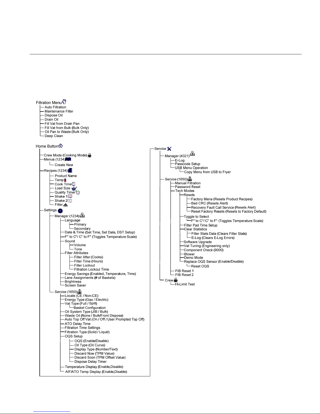
1.1 M4000 Menu Summary Trees
1.1.1 M4000 Menu Tree
Reflected below are the major programming sections in the M4000 and the order in which the headings will
be found in the controller.
1-1
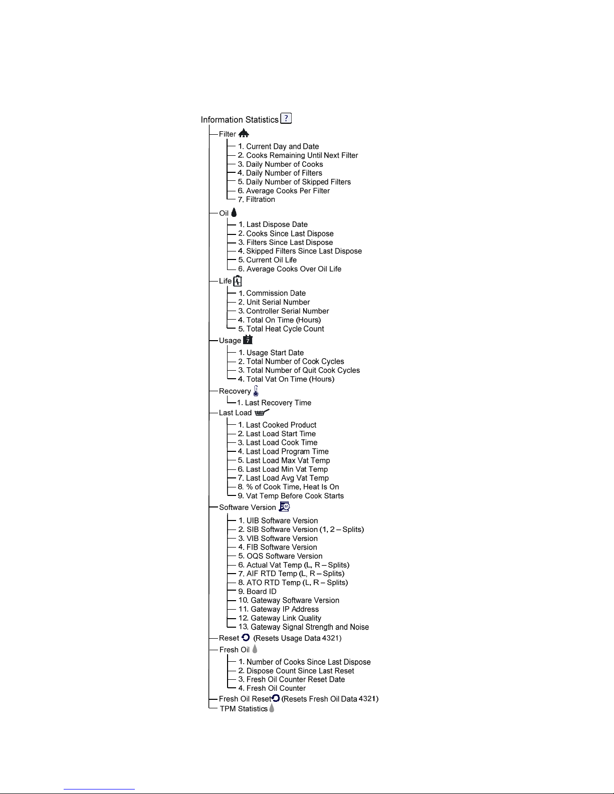
1.1.2 M4000 Information Statistics Menu Tree
Reflected below are the information statistics in the M4000 and the order in which the headings will be found
in the controller.
1-2
1.2 M4000 Password Codes
Press the HOME button to enter MENUS, RECIPES, SETTINGS or SERVICE menus.
1234 – MENUS, RECIPES, SETTINGS (MANAGER)
4321 – SERVICE (MANAGER)
1650 – SETTINGS (SERVICE), SERVICE (SERVICE) Enter Tech Mode
9000 – Component Check [SETTINGS (SERVICE), SERVICE (SERVICE) Enter Tech Mode]
The following code is entered when prompted to do so.
1111 – Reset SERVICE REQUIRED Message – Enter when the issue is fixed and prompted to enter
code.
1.3 Service Required Errors
A SERVICE REQUIRED error with a description of the error displays on the controller. After YES is pressed the
alarm is silenced. The controller displays an error message from the list below three times with the location of
the error. Then the controller displays SYSTEM ERROR FIXED? YES/NO. If yes is chosen, enter code 1111. If NO
is chosen, the system returns to cook mode if possible for 15 minutes, then redisplays error until issue is fixed.
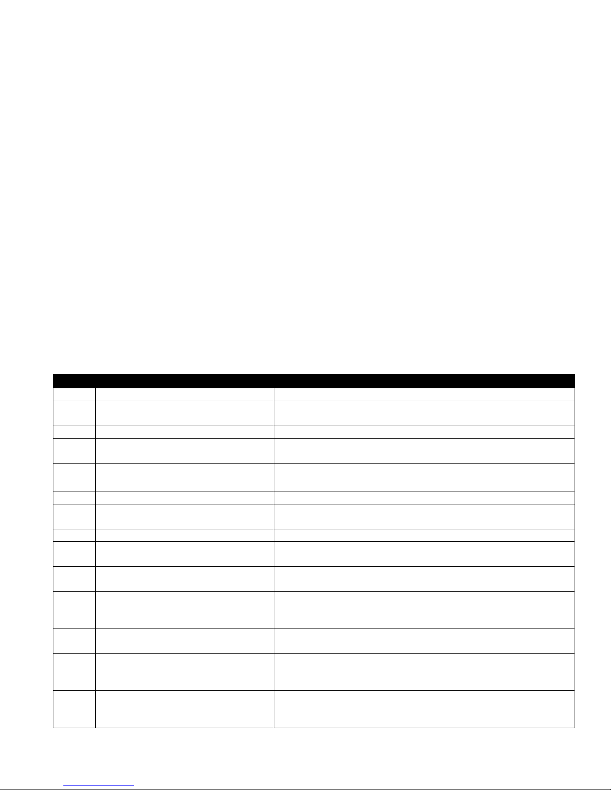
1.4 Error Log Codes
To access the error log, press the home button. Press the service button. Press the manager button. Enter
4321 and press the check button. Press the E-log button. The ten most recent errors are listed from top to
bottom, with the top error being the most recent error. A “G” indicates a global error such as a filtration error.
Side specific errors in split vats are indicated by L for left or R for right. Pressing the left down arrow allows
scrolling through the errors. If no errors are present the screen will be blank
.
Code ERROR MESSAGE EXPLANATION
E13 TEMPERATURE PROBE FAILURE TEMP Probe reading out of range
E16 HIGH LIMIT 1 EXCEEDED High limit temperature is past more than 410°F (210°C), or in CE
countries, 395°F (202°C)
E17 HIGH LIMIT 2 EXCEEDED High limit switch has opened.
E18 HIGH LIMIT PROBLEM
DISCONNECT POWER
E19 HEATING FAILURE – XXX F or XXX C Heating Control latch circuit failed.
E25 HEATING FAILURE - BLOWER The air pressure switch(s) failed to close.
E27 HEATING FAILURE - PRESSURE SWITCH -
CALL SERVICE
E28 HEATING FAILURE – XXX F or XXX C The fryer has failed to ignite and has locked out the ignition module.
E29 TOP OFF PROBE FAILURE - CALL
SERVICE
E32 DRAIN VALVE NOT OPEN - FILTRATION
AND TOP OFF DISABLED - CALL SERVICE
E33 DRAIN VALVE NOT CLOSED -
FILTRATION AND TOP OFF DISABLED CALL SERVICE
E34 RETURN VALVE NOT OPEN - FILTRATION
AND TOP OFF DISABLED - CALL SERVICE
E35 RETURN VALVE NOT CLOSED -
FILTRATION AND TOP OFF DISABLED CALL SERVICE
E36 VALVE INTERFACE BOARD FAILURE -
FILTRATION AND TOP OFF DISABLED CALL SERVICE
Vat temperature exceeds 460°F (238°C) and the high limit has failed
to open. Immediately disconnect power to the fryer and call service.
Heat Contactor failed to latch.
The air pressure switch has failed closed.
ATO RTD reading out of range
Drain valve was trying to open and confirmation is missing
Drain valve was trying to close and confirmation is missing
Return valve was trying to open and confirmation is missing
Return valve was trying to close and confirmation is missing
Valve Interface Board connections lost or board failure.
1-3
Code ERROR MESSAGE EXPLANATION
E37 AUTOMATIC INTERMITTENT FILTRATION
PROBE FAILURE - FILTRATION DISABLED
- CALL SERVICE
E39 CHANGE FILTER PAD 25-hour timer has expired or dirty filter logic has activated.
E41 OIL IN PAN ERROR The system detects that oil may be present in the filter pan.
E42 CLOGGED DRAIN (Gas) Vat did not empty during filtration
E43 OIL SENSOR FAILURE - CALL SERVICE Oil level sensor may have failed.
E44 RECOVERY FAULT Recovery time exceeded maximum time limit.
E45 RECOVERY FAULT – CALL SERVICE Recovery time exceeded maximum time limit for two or more cycles.
E46 SYSTEM INTERFACE BOARD 1 MISSING -
CALL SERVICE
E51 DUPLICATE BOARD ID - CALL SERVICE Two or more controllers have the same location ID.
E52 USER INTERFACE CONTROLLER ERROR -
CALL SERVICE
E53 CAN BUS ERROR - CALL SERVICE Communications are lost between boards.
E55 SYSTEM INTERFACE BOARD 2 MISSING -
CALL SERVICE
E62 SLOW HEATING FAILURE XXXF OR XXXC
- CHECK ENERGY SOURCE - CALL
SERVICE
E63 RATE OF RISE Rate of rise error occurred during a recovery test.
E64 FILTRATION INTERFACE BOARD FAILURE
- FILTRATION AND TOP OFF DISABLED CALL SERVICE
E65 CLEAN OIB SENSOR – XXX F OR XXX C -
CALL SERVICE
E66 DRAIN VALVE OPEN – XXXF OR XXXC Drain valve is opened during cooking.
E67 SYSTEM INTERFACE BOARD NOT
CONFIGURED - CALL SERVICE
E68 OIB FUSE TRIPPED – CALL SERVICE The VIB board OIB fuse has tripped and didn’t reset.
E69 RECIPES NOT AVAILABLE The controller has not been programmed with product recipes.
E70 OQS TEMP HIGH Oil temperature is too high for a valid OQS reading. Filter at a
E71 OQS TEMP LOW Oil temperature is too low for a valid OQS reading. Filter at a
E72 TPM RANGE LOW The TPM is too low for a valid OQS reading. This may also be seen
E73 TPM RANGE HIGH The TPM reading is too high for a valid OQS reading. Dispose the oil.
E74 OQS ERROR The OQS has an internal error. If issue continues contact a FAS.
E75 OQS AIR ERROR The OQS is detecting air in the oil. Check the O-rings and
E76 OQS ERROR The OQS sensor has a communication error. Check connections to
AIF (VIB Probe) RTD reading out of range.
SIB board 1 connection lost or board failure.
The controller has an unknown error.
SIB board 2 connection lost or board failure.
The vat is not heating properly.
Filtration Interface Board connections lost or board failure.
Gas -The oil is back sensor does not detect oil. Clean oil sensor (see
section 6.6.2 in BIGLA30-T IO manual).
Controller is turned on when the SIB board is not configured.
Replace controller with factory programmed controller.
temperature between 300ºF (149ºC) and 375ºF (191ºC).
temperature between 300ºF (149ºC) and 375ºF (191ºC).
with fresh new oil. The incorrect oil type may be selected in the
setup menu. The sensor may not be calibrated for the oil type. See oil
type chart in instruction document 8197316. If issue continues
contact a FAS.
check/tighten prescreen filter to ensure no air is entering the OQS
sensor. If issue continues contact a FAS.
the OQS sensor. Power cycle the entire fryer battery. If issue
continues contact a FAS.
1-4
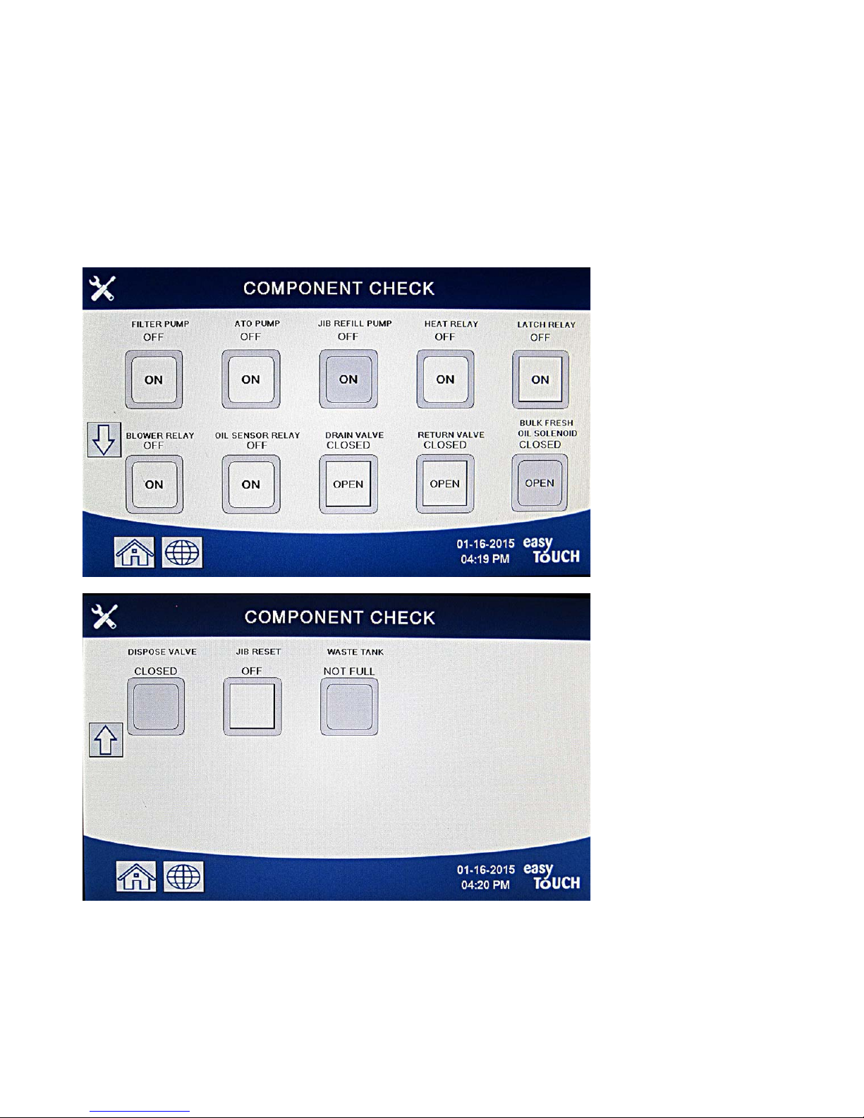
1.5 Component Check
The M4000 controller has a function to check the major components and their status.
With the controller soft powered OFF, press the HOME button. Select Service, Service, Enter 9000, Select Tech Modes, and
scroll down and select Component Check.
The component name is above each button. The status of the component is below the function. Pressing the button will
change the status of the function to what is stated on the button. If the button is shaded that function is not available
unless that function is enabled (such as bulk). The JIB reset button and Waste Tank full only displays the status of the
switch.
Pressing the home button to exit the function will display driving valves to ensure all valves return to home state. Once
completed the controller will display FILL VAT FROM DRAIN PAN? YES NO. Press YES to ensure that any oil in the filter pan
is returned to the vat.
1-5
1.6 Troubleshooting and Problem Isolation
Because it is not feasible to attempt to include in this manual every conceivable problem or trouble condition that might be
encountered, this section is intended to provide technicians with a general knowledge of the broad problem categories
associated with this equipment, and the probable causes of each. With this knowledge, the technician should be able to
isolate and correct any problem encountered.
Problems you are likely to encounter can be grouped into six categories:
1. Heating failure
2. Improper temperature control
3. Controller or board malfunctions
4. Filtration malfunctions
5. Auto Top Off malfunctions
6. RTI malfunctions
7. Leakage
The probable causes of each category are discussed in the following sections. A series of Troubleshooting Guides is also
included in each section to assist in solving some of the more common problems. The troubleshooting guides on the
following pages are intended to assist service technicians in quickly isolating the probable causes of equipment
malfunctions by following a logical, systematic process. An additional set of operators troubleshooting guides are contained
in Chapter 7 of the BIELA14-T Series Installation and Operation Manual. It is suggested that service technicians thoroughly
familiarize themselves with both sets.
1.6.1 General
Before performing any maintenance on your Frymaster fryer, disconnect the fryer from the electrical power supply.
WARNING
To ensure the safe and efficient operation of the fryer and hood, the electrical plug for the
120-volt line, which powers the hood, must be fully engaged and locked in its pin and sleeve
socket.
When electrical wires are disconnected, it is recommended that they be marked in such a way as to facilitate re-assembly.
1.6.2 Accessing Fryers for Servicing
DANGER
Moving a fryer filled with oil may cause spilling or splattering of the hot liquid. Follow the
draining instructions in section 5.3.7 in Chapter 5 of the BIELA14-T Installation and Operation
Manual before attempting to relocate a fryer for servicing.
1. Unplug the power cords.
2. Remove any attached restraining devices and relocate the fryer for service accessibility.
3. After servicing is complete, reattach restraining devices, and plug in the electrical cords. NOTE: To ensure the safe and
efficient operation of the fryer and hood, the electrical plugs for the 100-120-volt line, which may power the
hood, must be fully engaged and locked in its pin and sleeve socket.
1-6

1.7 Heating Failure
Heating failure occurs when the heating contactor fails to stay engaged and locks out. When this happens, the module
sends 24 VAC through the interface board alarm circuit to the controller.
M4000 controllers display “HEATING FAILURE”.
The three primary reasons for heating failure, listed in order of probability, are problems related to:
1. Electrical power supplies
2. Electronic circuits
3. Contactor issues
PROBLEMS RELATED TO THE ELECTRICAL POWER SUPPLIES
The main indicators of this are that the fryer does not operate and there are no indicator lights illuminated on the fryer
experiencing heating failure. Verify that the fryer is plugged in with connector twisted and locked and the circuit breaker
for the fryer electrical supply is not tripped.
PROBLEMS RELATED TO THE ELECTRONIC CIRCUITS
If electrical power is being supplied to the fryer, the next most likely cause of heating failure is a problem in the 24 VAC
circuit. Verify that the transformer is operating correctly. Refer to Section 1.7.4.
TROUBLESHOOTING THE 24 VAC CIRCUIT.
Some typical causes of heating failure in this category include a defective transformer, a defective relay, a defective
contactor, defective smart interface board (SIB) or defective elements.
1.7.1 Troubleshooting the 24 VAC Circuit
Prior to checking for problems associated with the 24 VAC circuit, ensure that the unit is connected to a power supply, and
the controller is on and is calling for heat (heat indicator appears and displays PRE-HEAT).
NOTE: All voltage measurements must be made within 4 seconds of the unit calling for heat. If unit has an error the
controller may lock out and controller must be turned off, then on to reset.
DO NOT CHECK WITH HARNESSES UNPLUGGED AS SHORTING THE PINS MAY OCCUR WHICH WILL DAMAGE THE
BOARD.
The following processes will assist you in troubleshooting the 24 VAC circuit and ruling it out as a probable cause:
24 VAC is not present on the interface board J1 pin 1.
1. If LED’s 2, 4 and 6 are not continually lit, the probable causes are a loose or blown fuse, failed 24 VAC transformer,
or failed wiring between the transformer and interface board.
24 VAC is present on interface board J1 pin 1.
1. If 24 VAC is not present at the latch contactor, the probable causes are an open high-limit thermostat, a failed latch
relay or a failed wire between the interface board and the latch contactor or a failed interface board.
a. Check continuity of high-limit thermostat. If it is zero, problem is in wiring.
2. If 24 VAC is not present at the heat contactor, the probable causes are a failed heat relay, latch contactor a failed
latch contactor, or a failed wire between the interface board and the heat contactor, a failed optional tilt switch or
a failed interface board.
3. If LED 3 is not continually lit with the controller in the ON position, the probable cause is a defective latch relay.
4. If LED 1 is not continually lit with the controller in the ON position and calling for heat, the probable cause is a
defective heat relay.
1-7
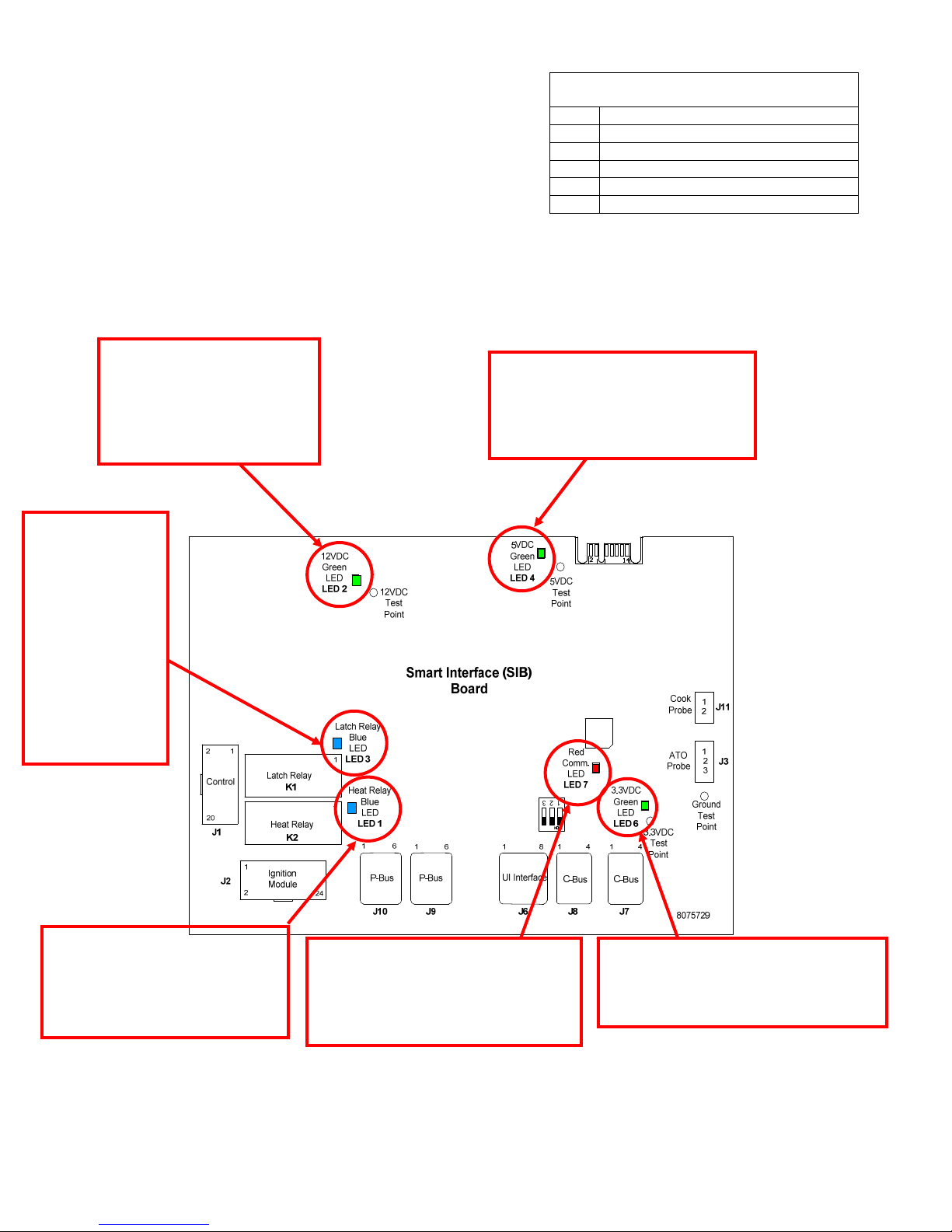
SMART INTERFACE BOARD LED DIAGNOSTIC
1.7.2 Smart Interface Board (SIB)
All fryers in this series have a smart interface board (SIB) located in the
component box behind the controller panel. The SIB board provides a
link between the controller and the fryer’s individual components
without requiring excessive wiring and executes commands from one
central point.
K2 is a single-pole-double throw (SPDT) relay that supplies 24VAC to the latch and heat circuits. The relays on this board
are soldered to the board. If a relay fails, the board must be replaced. K1 is a single-pole-double throw (SPDT) relay that
supplies voltage through the high limit switch.
The SIB LEDs (labeled LED1 through LED7) are arrayed around the board to assist in troubleshooting.
LED 1 24VAC Heat Relay
LED 2 12VDC to Controller
LED 3 24VAC Latch Relay
LED 4 5VDC to probes and switches
LED 6 3.3VDC to Micro Processor
LED 7 Communication to/from Micro Processor
LIGHTS
12VDC should be lit and
bright at all times. If LED (2) is
dim then something is pulling
voltage down. Short to
ground on 12VDC circuit will
cause dim LED.
5VDC should be lit and bright at all
times. If LED (4) is dim then
something is pulling voltage down.
Short to ground on 5VDC circuit will
cause dim LED.
When UI is soft
powered on this
Latch Relay LED
(3) will come on
first confirming
high limit is
closed. The relay
is a true latch
circuit and when
broken or turned
off the heat relay
will also turn off.
When UI calls for HEAT LED (1)
will come on with the heat relay
only after latch relay has been
latched in. This LED will cycle with
the call for heat.
Blinking red LED (7), (Heart Beat). This
LED should be blinking and bright at
all times when board is powered. The
other green LED’s being dim or off will
cause this LED to be off.
3.3VDC LED (6) should be lit and bright
at all times. If dim then something is
pulling voltage down. Short to ground
on 3.3VDC circuit will cause dim LED.
The chart in section 1.7.3 illustrates current flow through the board, and the table in section 1.7.4 identifies frequently used
test points.
1-8
 Loading...