


www.frsky-rc.com
FrSky Electronic Co., Ltd
Tel: (86) 0510-85187718 Fax: (86) 0510-85187728 E-mail: frsky@frsky-rc.com Technical Support: sales4tech@gmail.com
FrSky 2.4GHz ACCST
TARANIS X9D Digital Telemetry Radio System
User Guide

www.frsky-rc.com
FrSky Electronic Co., Ltd
Tel: (86) 0510-85187718 Fax: (86) 0510-85187728 E-mail: frsky@frsky-rc.com Technical Support: sales4tech@gmail.com
1
TABLE OF CONTENTS
BUTTON NAVIGATION ........................................................ 2
MAIN SCREENS....................................................................... 2
TELEMETRY VIEW ................................................................ 3
RADIO GENRAL SETTING MENU .................................... 4
PAGE1: RADIO SETUP..................................................... 4
PAGE2: SD CARD ............................................................... 5
PAGE3: TRAINER .............................................................. 5
PAGE4: VERSION .............................................................. 6
PAGE5: SWITCH TEST .................................................... 6
PAGE6: ANALOG INPUTS .............................................. 6
PAGE7: CALIBRATION .................................................... 6
MODEL SETTING MENU ..................................................... 7
PAGE1: MODEL SELECTION ......................................... 7
PAGE2: MODEL SETUP ................................................... 7
PAGE3: HELI SETUP ........................................................ 9
PAGE4: FLIGHT MODES ................................................. 9
PAGE5: STICKS ................................................................ 10
PAGE6: MIXER ................................................................. 10
PAGE7: SERVOS ............................................................ 112
PAGE8: CURVES............................................................... 14
PAGE9: GLOBAL VARIABLES ..................................... 12
PAGE10: CUSTOM SWITCHES ................................... 12
PAGE11: CUSTOM FUNCTIONS ................................. 13
PAGE12: TELEMETRY .................................................. 14
PAGE13: TEMPLATES ................................................... 18
GET START! ........................................................................... 16
FIRST STEPS ..................................................................... 16
SETTING UP A MODEL ................................................. 19
TARANIS BASICS ....................................................... 19
EVERYTHING ABOUT THE MIXER SCREEN ... 16
SERVOS SCREEN ........................................................ 19
STICKS SCREEN .......................................................... 20
MODEL SETUP GUIDELINES...................................... 20
ADVANCED FEATURES..................................................... 21
FLIGHT MODES ............................................................... 21
TELEMETRY ..................................................................... 21
AUDIO ................................................................................. 22
GLOBAL VARIABLES ..................................................... 22
A FEW INTERACTION EXAMPLES .......................... 22
MORE INFO: .......................................................................... 27
www.frsky-rc.com
FrSky Electronic Co., Ltd
Tel: (86) 0510-85187718 Fax: (86) 0510-85187728 E-mail: frsky@frsky-rc.com Technical Support: sales4tech@gmail.com
2
BUTTON NAVIGATION
TARANIS has 6 input keys: a standard set of +//ENTER/EXIT, plus 2 contextual MENU and PAGE
keys. On the main views, the PAGE key will switch
between the different views described in the next
section. A long press of the PAGE key will bring up
the telemetry display from main screen. A short
press of the MENU key will call the model menu,
while a long press will call the radio settings menu.
In those 2 menus, a short press of the PAGE key
goes to the next page, while a long press goes back
to the previous one. EXIT goes back to the main
views. On the STICKS and MIXER model menu
pages, a long press of the MENU key will bring up a
channel monitor to allow quickly looking at the
result of a change in settings.
The navigation in a menu is simple: The +/- keys
will navigate up/down between editable fields, or
lines of fields depending on the screen. ENTER will
enter the line of fields when applicable, then edit
mode. In edit mode, +/- will change the value,
ENTER or EXIT will validate the input and return to
navigation. EXIT always goes back to the previous
navigation level.
In edit mode, we have four 2-key shortcuts
available: +/- together: Invert value -/ENTER : Set
value to 100 EXIT/PAGE: Set value to -100
MENU/PAGE: Set value to 0
Another handy feature is the auto selection of
physical inputs in the relevant fields. Instead of
choosing a source or switch with the + and - keys,
just move the pot or flick the switch you want, and
it will be recognised. For switches the position is
also auto-selected, and the +/- double key
combination will allow selecting the opposite
position in a pinch.
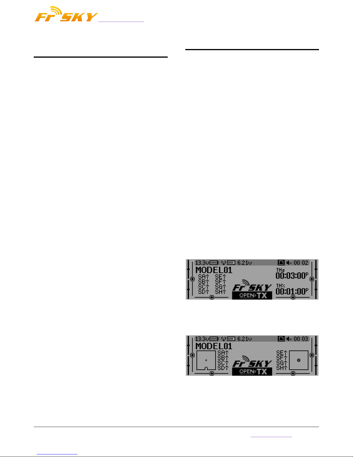
MAIN SCREENS
TARANIS has 4 main views showing the same
basic information in the top part and different
inputs/outputs on the lower part. On the main
views a long press of the ENTER key brings up a
menu where you can reset the timers, telemetry
data (min/max), all of those, or bring up a statistics
view (throttle graph, timers). As mentioned above,
a short press of the PAGE key switches views. The
new title bar includes radio battery voltage,
receiver signal strength (for FrSky receivers), main
onboard voltage (can be receiver battery, flight
battery, or anything else depending on sensors the
"Voltage" parameter in the telemetry settings),
status icons (micro SD present, USB connected,
trainer port mode, logging in progress), audio
volume and time. The other "always present" items
are model name, flight mode, and trim/pot
positions. The logo is of course customisable - if you
have a micro SD card in your radio, you'll be able to
load your model's photo there!
The first view lists the physical switch states in
the bottom left zone, and the 2 timers (when
enabled) on the right.
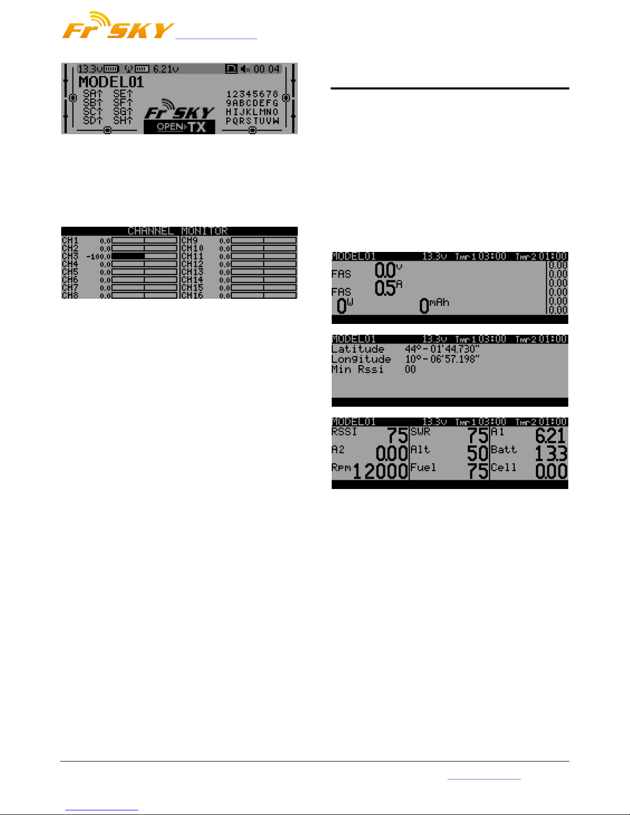
The second shows the gimbal and switches
positions, and is handy to check that all the physical
controls respond as intended.
The third shows again the physical switches on
the left, and the states of the 32 custom (logic)
switches on the right.
www.frsky-rc.com
FrSky Electronic Co., Ltd
Tel: (86) 0510-85187718 Fax: (86) 0510-85187728 E-mail: frsky@frsky-rc.com Technical Support: sales4tech@gmail.com
3
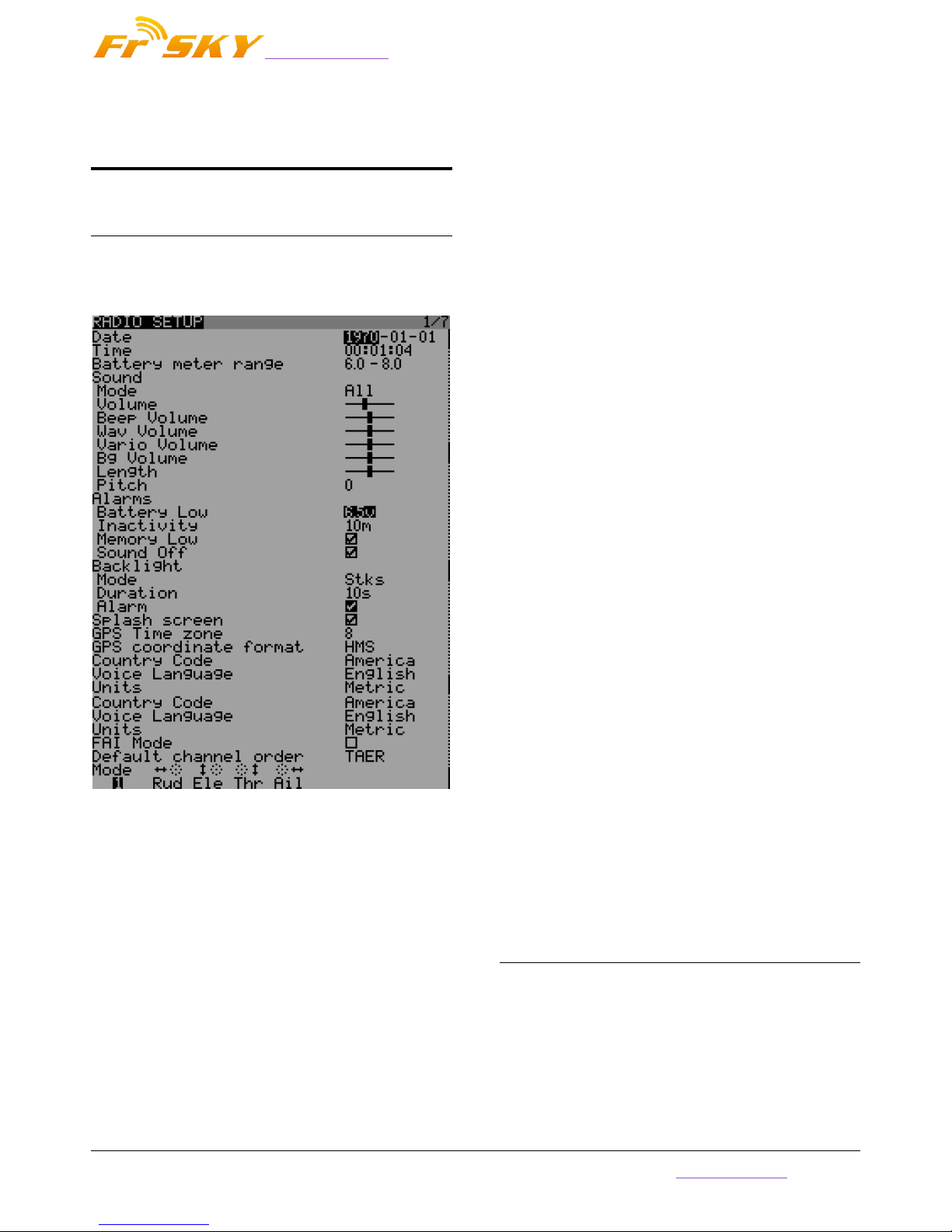
The last view is a channel monitor showing the
servo outputs for all 32 channels (+/- change page).
If channel names are defined on the SERVOS page,
they will show up here instead of the numbers for
convenience.
TELEMETRY VIEW
A long press of the PAGE key from any of the
main views brings up the telemetry views. The
PAGE and +/- keys will then cycle between the
power status screen (voltage, current, power or
A1/A2 if not set, cell voltages from an FLVS-01
sensor if connected), the min/max and GPS
coordinates screen, and if defined from one to three
customs screens that can hold up to 12 items each,
configured in the telemetry setup menu.
www.frsky-rc.com
FrSky Electronic Co., Ltd
Tel: (86) 0510-85187718 Fax: (86) 0510-85187728 E-mail: frsky@frsky-rc.com Technical Support: sales4tech@gmail.com
4
RADIO GENRAL SETTING
MENU
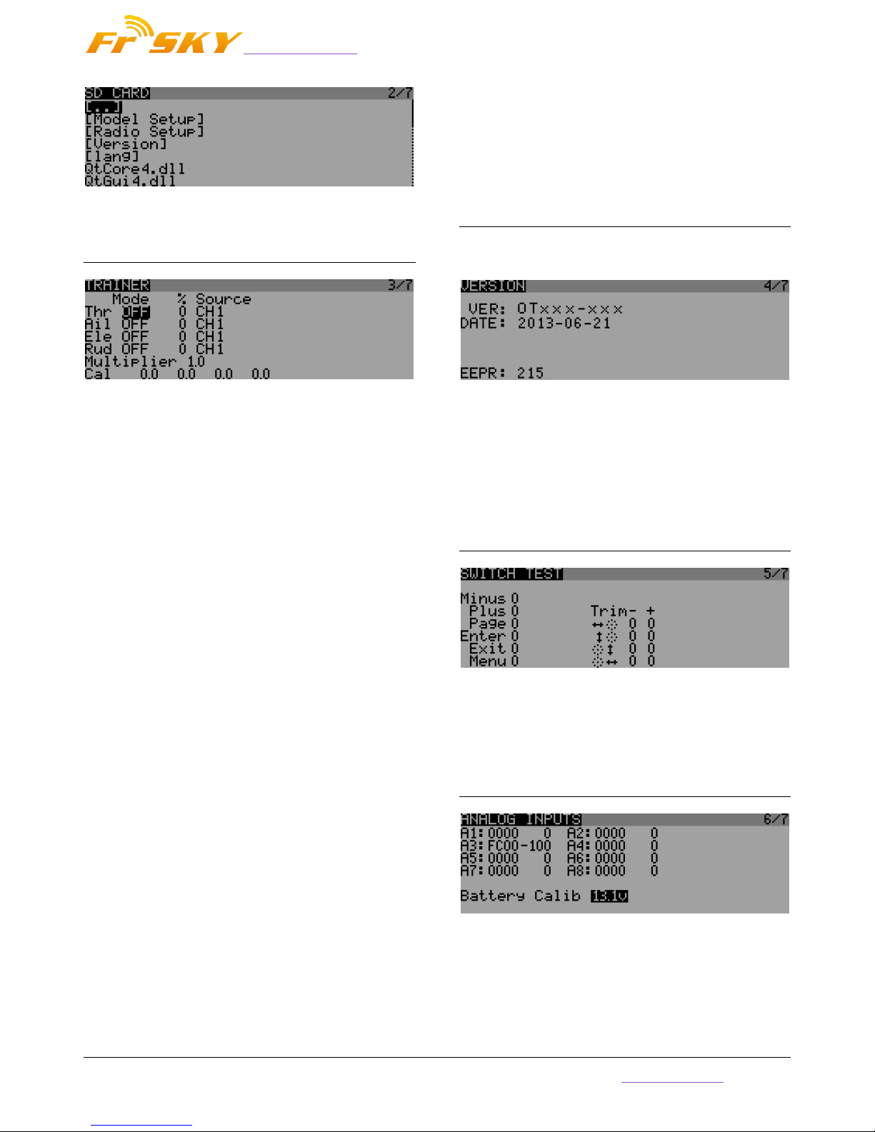
PAGE1: RADIO SETUP
A long press of the MENU key from any of the
main views brings up the mostly self-explanatory
radio setup menu:
Date/Time: To be set, they serve as info but
also to give a correct time stamp to files and
logs saved by the radio.
Battery range: range of the graphical radio
battery meter on the main views. To be set
accordingly with the battery type you use .
Sound: set the mode, length, pitch, volume of
the system beep.
Alarms: set the alarm values for battery low,
inactivity and memory low . Sound off: if
"Sound Mode" is "Quiet", the radio will not
even sound warnings like a low battery. This
alarm will remind you of that when turning the
radio on.
Backlight -> Mode: If set to Stks, Keys or Both,
the backlight will turn on when a stick is
moved and/or a key is pressed, for the
duration set below.
Backlight -> Duration: set the duration for each
lighting.
Backlight -> Alarm: Backlight will flash when
an alarm sounds if it's not already on at that
time.
Splash screen: On TARANIS the splash will
always be shown as the EEPROM takes some
time to load. Setting this on will just show it for
longer.
GPS Time Zone: set the time zone of your area.
Country code: Must match your geographical
location to keep RF transmission parameters
within regulatory requirements.
Default channel order: Defines the order of the
4 default mixers that are inserted on channels
1-4 when creating a new model. Set this to
your preference. They can of course always be
moved later, this is just a time-saving option.
Mode: This is your stick mode, e.g. Mode 1 for
throttle and aileron on the right stick, Mode 2
for throttle and rudder on the left stick.
PAGE2: SD CARD
By short pressing the PAGE key from RADIO
SETUP view it will bring up the micro SD browser
where you can copy/rename/delete files and
preview sounds
www.frsky-rc.com
FrSky Electronic Co., Ltd
Tel: (86) 0510-85187718 Fax: (86) 0510-85187728 E-mail: frsky@frsky-rc.com Technical Support: sales4tech@gmail.com
5
PAGE3: TRAINER
Pressing the PAGE again,TARANIS will show the
trainer function menu. This menu allows the PPMin
(trainer) inputs to be configured. It enables the
RAW PPM inputs to be selected to replace the sticks
for training purposes. The student transmitter does
not need to have the same model setup as the
instructor. All the mixes on the instructors Tx will
be applied to the student inputs. If, for example, you
have expo on your sticks, this will be applied to the
raw trainer inputs when they are selected.
The mode entry selects how the PPMin value is
used:
off unused
+= add to instructor stick value
:= replace instructor stick value
The % entry applies a weighting to the PPMin
value -100 to 100, Use -100 to reverse the
input. Use values closer to 0 to reduce the
students control sensitivity.
Multiplier 0.0 to 5.0 scale for PPMin values.The
multiplier does as it's name suggests. It
multiplies the ppm Input by a set amount.
Great for dealing with different tx's whose
makers don't know how to encode PPM.
CAL: Center calibration for first 4 PPMin
values.This entry allows you to calibrate the
mid point for the first 4 input PPM
channels.Highlighting “Cal” and pressing
[MENU] will calibrate the mid point for all PPM
IN channels.
PAGE4: VERSION
This screen shows the version information for
the current firmware version.
VER: The version of the current firmware.
DATE: Compile date for the current
firmware.
EEPR: The eeprom space has been used
PAGE5: SWITCH TEST
This menu will help you to visualize the current
state of the trims and navigation keys.
PAGE6: ANALOG INPUTS
Here you can see the analog inputs in
hexadecimal format to save space and annoy
you at the same time.
A1..A4 are the gimbals (sticks).
www.frsky-rc.com
FrSky Electronic Co., Ltd
Tel: (86) 0510-85187718 Fax: (86) 0510-85187728 E-mail: frsky@frsky-rc.com Technical Support: sales4tech@gmail.com
6
A5..A8 are the pots and slides.
Battery Calibration: you can calibrate the
voltage value of the tx’s battery here.
Do not change it if you have not measure the
battery voltage by voltmeter.
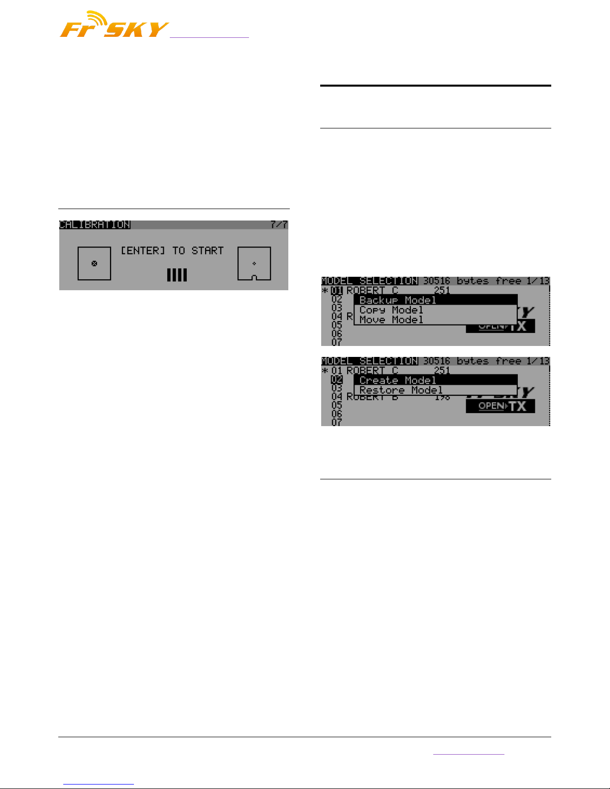
PAGE7: CALIBRATION
This screen allows you to calibrate the analog
channels (A1..A8).If you want to do this, just follow
the word displayed on the screen.
MODEL SETTING MENU
PAGE1: MODEL SELECTION
A short press of the MENU key from the main
views brings up the model selection screen. There
models can be selected, deleted, backed up and
restored to/form SD card using the menu brought
up by a long press on the ENTER key. They can also
be copied or moved (one short press on ENTER key
highlights the line, +/- create and place a copy of
the model on the desired slot, while two short
presses create a dotted outline where +/- simply
move the current model to another slot.)
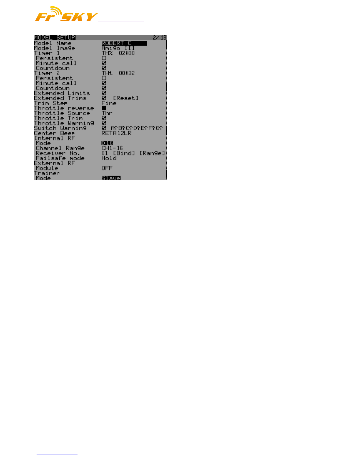
PAGE2: MODEL SETUP
A short press of the PAGE key brings up the
basic model setup page:
www.frsky-rc.com
FrSky Electronic Co., Ltd
Tel: (86) 0510-85187718 Fax: (86) 0510-85187728 E-mail: frsky@frsky-rc.com Technical Support: sales4tech@gmail.com
7
Model image: There you can select a 64x32px,
4-grayscale .bmp file located in the BMP folder
of the micro SD as your model logo.
Timers: Persistent, if ticked, means the value is
stored in memory when the radio is powered
off or model is changed, and will be reloaded
next time the model is used. Minute call will
beep / say the time every full minute, while
countdown will also give announcements
several more times during the last minute. ABS
counts up all the time, THs runs whenever the
throttle stick isn't at idle, THt starts the timer
the first time throttle is advanced, TH% counts
up as a percentage of the full stick range.
Extended limits allow setting servo movement
limits up to 125% instead of 100%.
Extended trims allows trims to cover the full
stick range instead of +/-25%. The "Reset"
item will reset all trims (for all flight modes).
Trim step sets the precision of trim clicks.
Exponential means very fine steps close to the
trim center, but larger one the farther you get
from center.
Throttle reverse: Ensures correct operation of
throttle-based timers and functions for people
who like having full throttle with the stick
down.
Throttle source defines what triggers the THx
functions of the timers. It's common to set it to
the throttle channel instead of the stick, so that
throttle cut or other modifiers are taken into
account.
Throttle Warning: TARANIS would give you a
warning if the throttle is not idle when power
on.
Throttle trim: IC engine mode, where trim only
affects the idle part of the throw without
touching the full throttle point.
Switch warning: Defines whether the radio
requests the switches to be in predefined
positions on power on/model change. To set
them, arrange your switches the way you like,
and long press ENTER.
Center beep: Makes a beep when the active
control(s) pass the center point.To set them,
press ENTER and move the cursor, then press
ENTER to confirm.
Internal RF:
o Mode: Transmission mode of the internal
RF module (OFF, D16, D8, LR12).
o Channel range: Choice of which of the
radio's internal channels are actually
transmitted over the air.
o Receiver no. defines the behavior of the
receiver match function. This number is
sent to the receiver, which will only
respond to the number it was bound to. By
default this is the number of the model's
slot when it is created. It can however be
changed manually, and will not change if a
model is moved or copied. If manual
setting, a move or copy operation results
in 2 or more models on the radio having
the same number, a warning popup will
show up. It is then up to the user to
 Loading...