

FrSky S.Port Dashboard User Manual
FrSky Electronic Co., Ltd
Website:www.frsky-rc.com E-mail:frsky@frsky-rc.com Technical Support: sales4tech@gmail.com
FrSky Electronic Co., Ltd
Website:www.frsky-rc.com E-mail: frsky@frsky-rc.com Technical Support: sales4tech@gmail.com
1. Introduction
www.frsky-rc.com
www.frsky-rc.com
2. Installation
3. Screen Structures
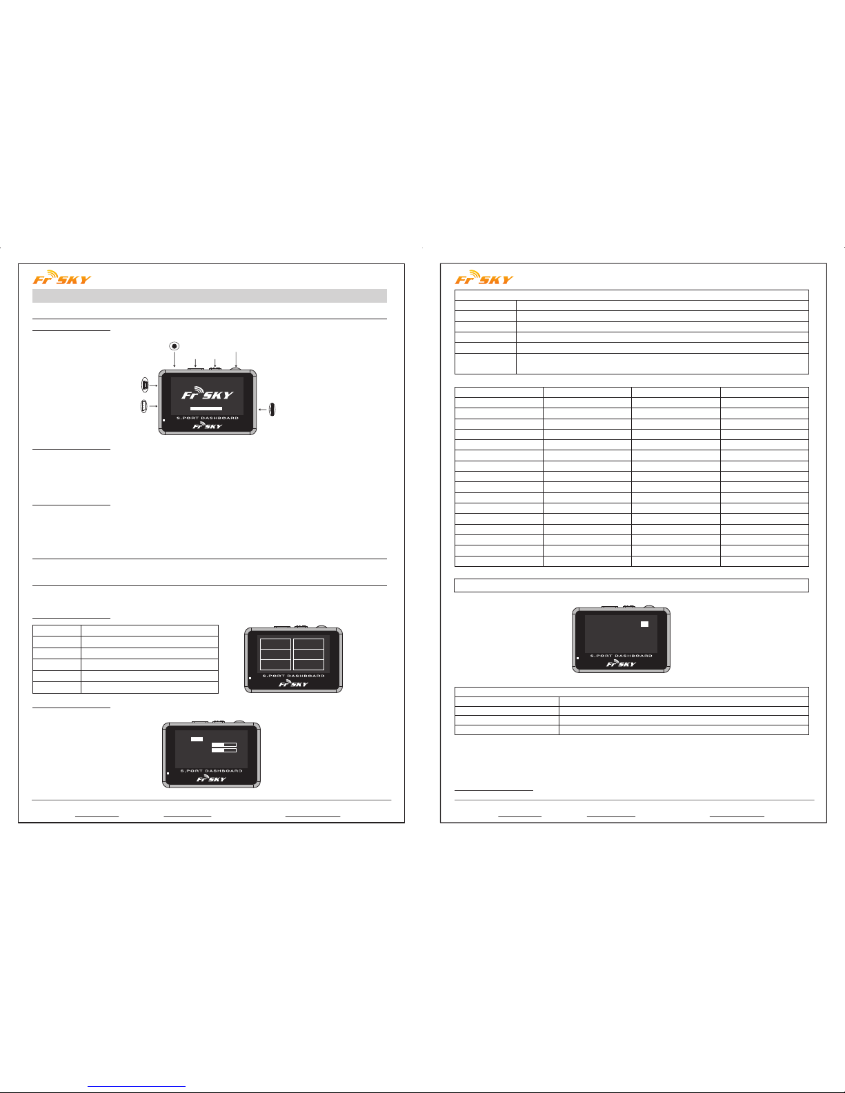
1.1 Overview:
1.2 Specifications:
1.3 Features:
3.1 Main screen:
3.2 SYSTEM screen:
Instruction Manual for FrSky S.Port Dashboard
Earphone Part
Page Power Switch
Rotate Switch
TF Card Slot
USB Port
+
S.Port
Model Names: FSD (FrSky S.Port Dashboard)
Compatibility: FrSky X Series Telemetry Modules
Voltage Range: 4.8~6V
Dimension: 75*50*13.8mm
Pixel: 128*64
1) Show all connected sensors data;
2) Capable of programming alarm thresholds and system settings;
3) Set Physical ID and Group Number for S.Port sensors;
4) Firmware upgradeable for all S.Port products.
Connect FrSky FSD to the S.Port on FrSky X series telemetry module (S.Port, VCC, GND) by the provided cable.
Use “rotate switch” to choose, short press “rotate switch” to confirm, short press “page” to the next page, hold
“page” for 1 second to go back to previous screen.
SYSTEM
VOICES
UPDATE
DATA
IDSET
INFO
System settings
Settings
Upgrade S.Port devices
Telemetry data display
Set phyID and GNum for S.Port sensors
Firmware and Eeprom version
System Set
Units
Contrast
Volume
Log Interval
Time Zone
SYSTEM DATA
IDSET
INFO
VOICES
UPDATE
*System Set
Units: metric celcius
Contrast:
Volume:
Log Interval: 1s
Time Zone: 000
Alarm: Height Dis < 000
-
- +
+
metric or imperial (selectable), fahrenheit or celcius (selectable)
adjust the contrast of the screen
adjust the volume of the voice
data log period (0.1s, 0.5s, 1s, 2s, 5s selectable)
-11 to 12 time zone selectable (”-” is west and “+ ”is east)
use “rotate switch” to choose, short press “rotate switch” to change the setting
(see detailed chart below)
Alarm
Alarm
Height
HeightC
A1
A1C
A2
A2C
A3
A3C
A4
A4C
RxBat
RxBatC
SWR
SWRC
RSSI
RSSIC
Sensor
Variometer
Variometer
Receiver
Receiver
Receiver
Receiver
S.Port2UART
S.Port2UART
S.Port2UART
S.Port2UART
Receiver
Receiver
Module
Module
Receiver
Receiver
Direction
>
>
<
<
<
<
<
<
<
<
<
<
>
>
<
<
Unit
10m
10m
0.1V
0.1V
0.1V
0.1V
0.1V
0.1V
0.1V
0.1V
0.1V
0.1V
Note: “C” after the alarm name means “critical”.
*Sensor Set
RPM Sensor blade: 02
Anolog Sensor
Volt ratio:
04 04 04 04 04
GPS Sensor Enabled
Flvss Sensor Enabled
Sensor Set
RPM Sensor blade
Anolog Sensor Volt ratio
GPS Sensor
Flvss Sensor
Set the blade numbers for RPM Sensor
Voltage Division Ratio for A1, A2, A3, A4, RBat
Enable or Disable the GPS data screen (Page 4 of DATA screen)
Enable or Disable the Lipo Voltage data screen (Page 5 of DATA screen)
Follow the steps below to change “System Set” and “Sensor Set”:
Step 1: Short press “rotate switch” to open “system set”;
Step 2: Use “rotate switch” to choose the position you want to change;
Step 3: Short press “rotate switch” to change the settings.
3.3 VOICES screen:
FrSky Electronic Co., Ltd
Website:www.frsky-rc.com E-mail:frsky@frsky-rc.com Technical Support: sales4tech@gmail.com
FrSky Electronic Co., Ltd
Website:www.frsky-rc.com E-mail: frsky@frsky-rc.com Technical Support: sales4tech@gmail.com
www.frsky-rc.com
www.frsky-rc.com
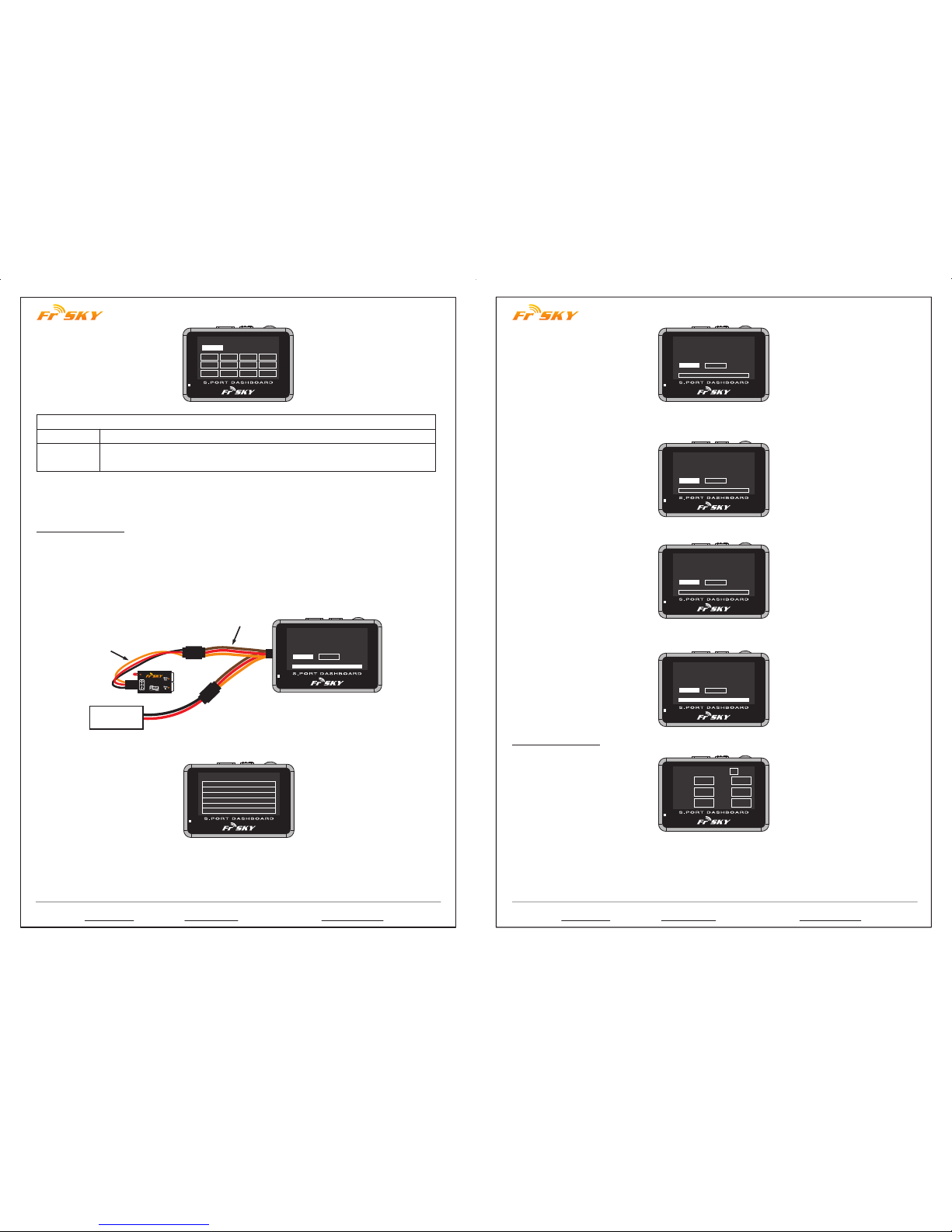
3.4 UPDATE Screen:
Voice Set
Select
5S
SWR RSSI RBat A1
A2 A3 A4 Valt
Vspd CUR1 Vcu1 TEM1
Voice Set
Select 5S
Voice can be set to “All off”, “All on”, “Select”
Time interval for the voice announcement (5s, 10s, 20s, 30s, 1m, 1.5m, 2m selectable
under “Select”)
Follow the steps below to change “Voice Set”:
Step 1: Short press “rotate switch” to open “system set”;
Step 2: Use “rotate switch” to choose the position you want to change;
Step 3: Short press “rotate switch” to change the settings.
FrSky FSD could upgrade FrSky S.Port products (including modules, receivers, sensors and other S.Port
enabled devices). Follow the steps below to finish the upgrade.
Step 1: Create a new folder named “S.PORT” in the TF card by PC;
Step 2: Download the firmware from FrSky website and put the frk. firmware into the “S.PORT” folder;
Step 3: Insert the TF card back into the FSD card slot;
Step 4: Connect the battery to the FSD by the Y harness, and use rotate switch to choose UPDATE on the main
screen and short press to enter UPDATE screen;
VARIO2.frk
Device found!
Firmware is updated
UPDATE BACK
LED
PORT
Variometer
Sensor
Battery
s.port
“Y” Cable
Step 5: Use rotate switch to choose the frk. firmware you want to upgrade and short press to open;
To Updated Files
FLVSS.frk
VARIO2.frk
Step 6: Connect the right device to FrSky FSD by the Y harness;
VARIO2.frk
Pls connect device!
Searching....
UPDATE BACK
Step 7: After the screen shows “Device found! Please click UPDATE”, choose and short “UPDATE” to confirm
update or “BACK” to quit the update;
VARIO2.frk
Device found!
Please click UPDATE!
UPDATE BACK
Step 8: Wait for flashing;
VARIO2.frk
Device found!
Wait for flashing...
UPDATE BACK
Step 9: After the firmware is updated, choose and short press BACK to go back to the update screen.
3.5 DATA Screen:
VARIO2.frk
Device found!
Firmware is updated
UPDATE BACK
00 : 03 : 39
SWRTF0
P1
RSSI 0
RBat 0.0
0.0
A1
A2 0.0
0.0
A3
Time: H/M/S (If GPS sensor is connected, the time will be GTM in 10 seconds; if not, the time will be your
operation time)
TF: If the FSD has the TF card inserted already, here will have the TF logo; if not, here will show ER (error).
Short press “rotate switch” will activate the TF to be “ON”, meanwhile start to log your telemetry data.
P: Number of pages
 Loading...