

Page 1
Alexander “Datos”
«http://forum.modelka.com.ua»
Using FrSky FLD-02 + battery level sensor FrSky FBVS01 + FrSky
D8R-II receiver. Short manual.
1.1 Specifications of
FrSky FLD-02
:
Model: FLD-02
Compatibility: FrSky DFT, DJT and DHT
Dimensions: 55*40*12mm
Screen resolution: 128*64
Backlight: yes, light-cyan
Power: from TX
1.2 Features:
1) Shows data from any compatible sensors connected to RX
2) Programmable alarms
3) Upgradable firmware
2 Quick start:
Connect FrSky FLD-02 to FRSky TX module using the cable supplied with FLD-02. Maintain polarity:
black wire means - ground. Make sure that both switches of FRSky TX module are at “OFF” position.
3 Screen structure:
3.1 Main screen:
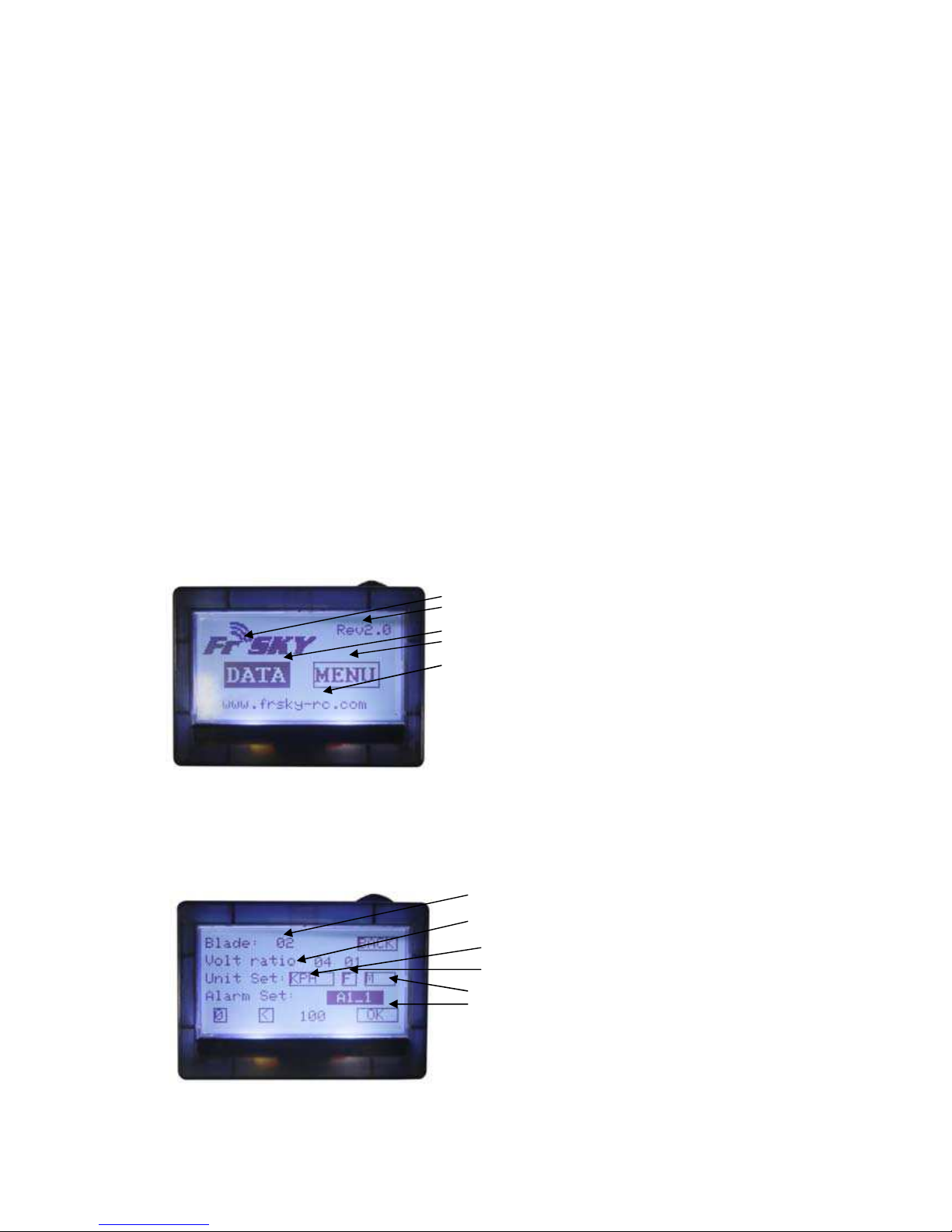
FrSky logo
Firmware version
«DATA» button
«MENU» (settings) button
FrSky website
*note: you can scroll through buttons|values|digits by rotating upper button to either direction. Short
button press would choose|confirm value. Turning and keeping button for more than 1 second at
either end would set the cursor to the next location in more-than-one digit cell.
3.2 «MENU» Screen
Blаde: # of blades
Volt ratio: voltage divider on A1 (left cell) & A2 (right
cell) ports
Unit Set: Speed (KPH | MPH)
Temperature: (C | F)
Altitude: (meter | feet)
Alarm Set: alarm setup for A1_1/2, A2_1/2, RSSI_1/2
Page 2
3.2.1 D8R-II receiver (additional information)
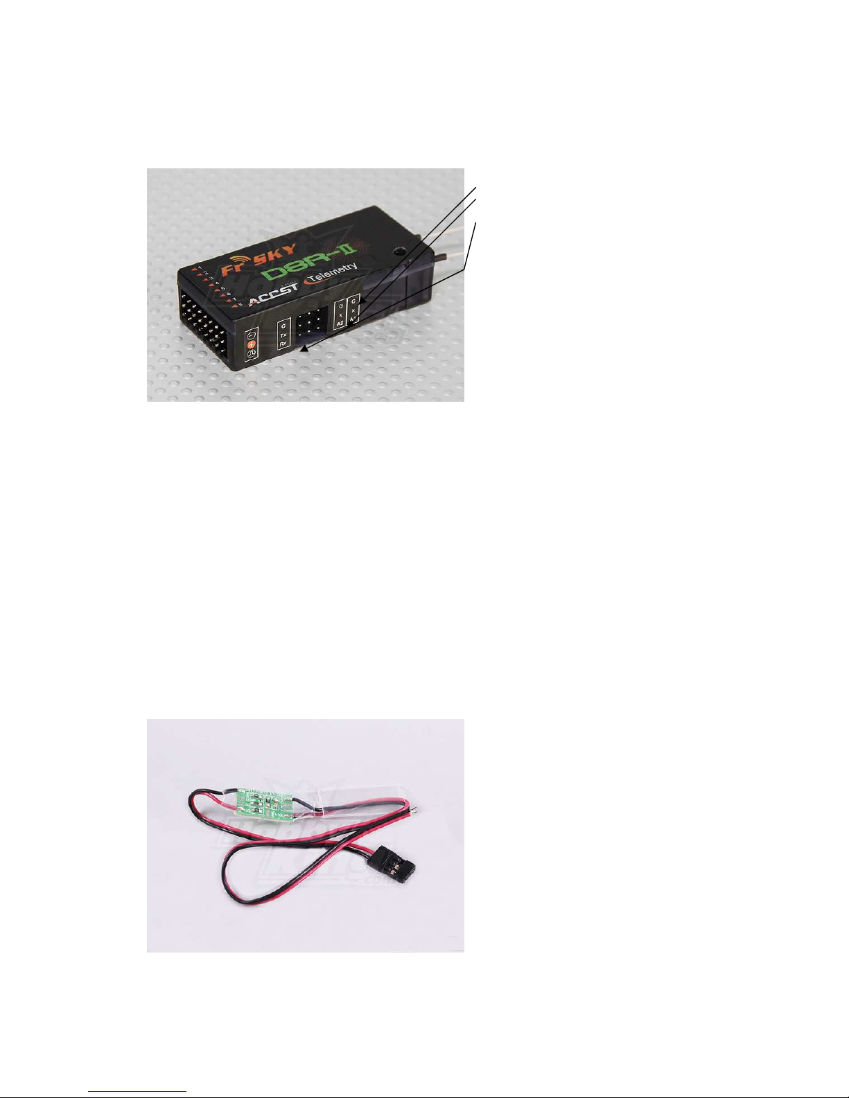
D8R-II receiver has 2 telemetry ports A1 and A2 (you can simultaneously connect either only 2 of
any telemetry sensors or more than 2 sensors by using special sensor-hub) + 1 firmware upgrade
port.
A1
A2
Firmware upgrade port
Port A1 has a default bridge installed from the factory between Х and A1 pins. Pin Х supplies power
to a sensor. А1 pin receiver data from a sensor. G stands for Ground.
Therefore, if there is a bridge between X and A1 pins – telemetry screen FLD-02 would show the
inner RX voltage in the left cell “A1 & A2 Voltage” (look at section 3.3.1 of this manual) The readings
of this cell A1 (left) on “DATA Screen 1” would be true (4.2V) only in case if voltage divider for A1 is
set correctly. Don’t forget that this is stabilized voltage inside the RX circuit that is supplied either by
ESC (in case of using only 1 battery in RC-model) or separate battery used to power-up electronics.
Consequently, this reading could not be used as a reference to overall main battery charge level.
In order to setup an appropriate voltage divider you should turn to “MENU” Screen (look at
section 3.2 of this manual) “Volt Ratio” value (left value stands for А1 port)). This value should be
equal to the number of cells of the battery, that supplies voltage to the receiver (3 for 3-cells LiPO). If
this value is set correctly – it would read 4.2V
Furthermore, apart from A1 inner RX voltage readings, you can connect FBVS01 battery voltage
sensor to A2 RX telemetry port.
Page 3
3.2.2 FBVS01 external battery level telemetry sensor
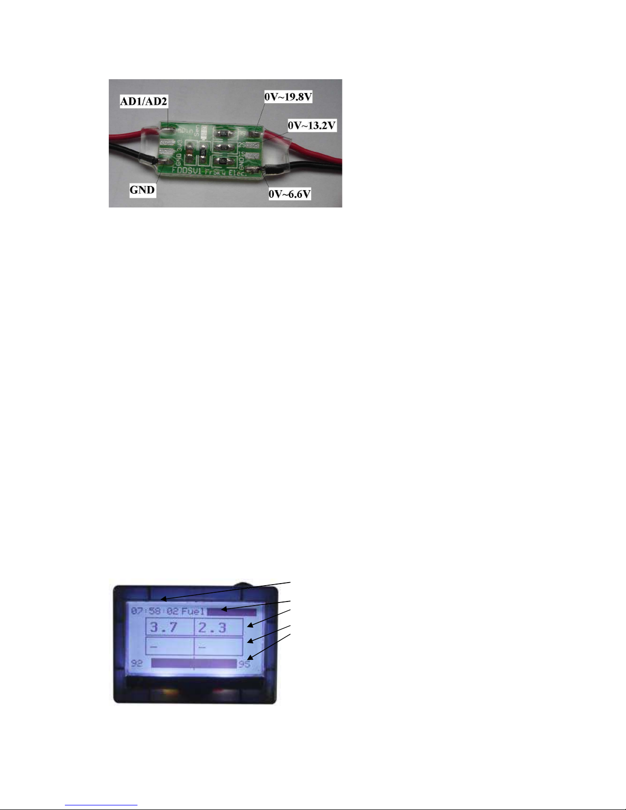
This sensor has 3 voltage dividers - soldering
pins: 1S (1-2 cell LiPO max. Divider for FLD02 = 2), 2S (1-4 cell LiPO max. Divider = 4),
3S (1-6 cell LiPO max. Divider = 6).
Initially, red wire that goes to the battery is soldered to 3S pin on board, i.e. – any LiPO battery from
1 to 6 cells. In case of using, for example, up to 4 cells – you should re-solder it to 2S pin in order to
get more accurate voltage metering by the sensor.
*from now on – we would use 3-cell LiPO (11.1V) as an example….
After re-soldering red wire to 2S pin, connecting this wire to the battery, and connecting FBVS01
sensor to RX A2 telemetry port – you would have to setup the appropriate voltage divider for our
specific soldering type in order to have the appropriate readings in A2 cell (right) of “A1 & A2
Voltage” section (look at section 3.3.1 of this manual) of “DATA Screen 1”. To do this – go to
“MENU” Screen (section 3.2 of this manual) and set the appropriate divider value for A2 in “Volt
Ratio” section (as it is stated above, near the picture with soldering pins layout), i.e. 4 (for our
soldering type 2S and 3-cell LiPO battery).
*note: if you are using only 1 battery in you RC-model (without separate battery for electronics) –
you should NOT use|connect black (Ground) wire of voltage sensor. Just do NOT connect it. Throw
it away or cut it, or just forget it. The only cable that should be connected to RX and battery – red (+).
In case of 1 battery, Ground is already supplied to the RX from ESC. If you would supply another
one Ground through sensor to RX telemetry port – you would have Ground-loop because electrons
would follow the lowest-resistance route omitting long RX-electronic circuit. It would eventually result
into electronics (gyro, servo, etc) short-time or permanent failure.
In case if you use 2 separate batteries – 1 for electronics and another one to power-up the motor
and you are connecting sensor to motor-battery – you can use + and – without any ground-loop.
How to setup an alarm for sensor readings (look at section 3.3.2 of this manual)
3.3 DATA Screen:
3.3.1. Screen-1
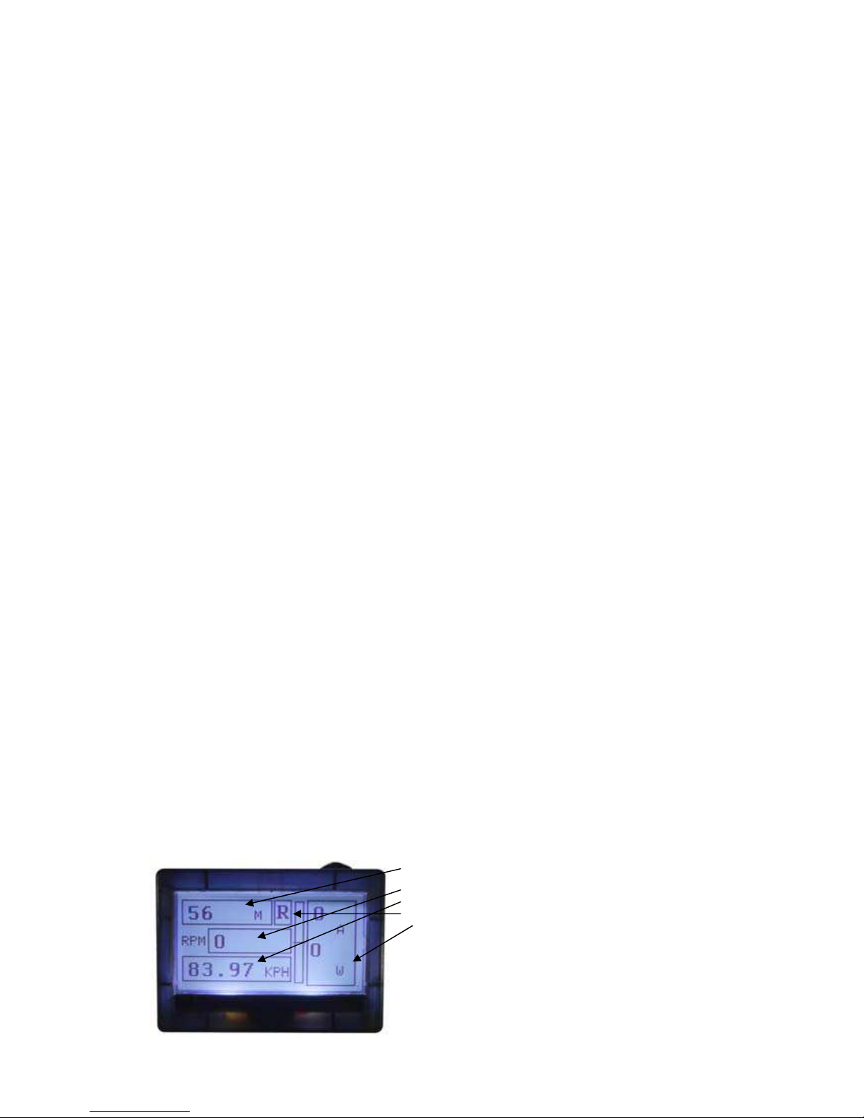
GMT (h/m/s)
Fuel level
A1 & A2 Voltage ( readings from А1 and А2 RX ports)
Temperature 1 & 2
Rx RSSI (level of RX signal) & Tx RSSI (level of TX signal)
*note: RX and TX signal level is shown without any sensors attached to RX. This is default built-in
function. This function also allows alarms to be set (look at section 3.3.3 of this manual)
Page 4
3.3.2 How to setup an alarm for battery sensor readings (3-cell LiPO, connected to A2
telemetry RX port)
In order to program low-battery alarm at a certain battery level, you should go to “MENU” Screen
(section 3.2 of this manual) and than in “Alarm Set” section choose A2_1 and enter the following
values underneath:
1 < 218
Where:
1 – is a level (volume/frequency/number) of beeps (0 – no beep, 1 – low beep, 2 – meduim, 3 –
high)
< - means lower than
218 – a value at which alarm starts working
WHY 218???? 218, in this case means = 11.25V. i.e., 3.75V/cell for 3-cell LiPO. How to calculate
this value or setup your own:
(desired Voltage (V) / voltage divider (4 – as it is defined by our soldering type) / 3.3V) х 256
(number of values that A/D converter can have, from 0 to 255)
Example: we want alarm to sound when 3-cell LiPO would reach 11.25V (3.75V/cell) discharge level:
(11.25V / 4 (divider for 2S soldering type) / 3.3) х 256 = 218
Now, using this formula – you can calculate the appropriate value for any battery discharge level.
Moreover, you can setup 2 alarms for the same sensor|port. For example, alarm could sound low at
12V level and sound high at 11.23V level. To do this, go to “MENU” Screen (section 3.2) and set all
values for A2_1 and than A2_2 alarms in “Alarm Set” section. Last digits here stand for 1-st and 2-nd
alarm.
3.3.3 How to setup RX-TX signal level alarm
In order to setup an alarm for RX-TX signal fall-down/loss – you should go to “MENU” Screen
(section 3.2) and in “Alarm Set” section choose RSSI and set the following values underneath (as
recommended in the manual):
RSSI_1
1 < 45
RSSI_2
2 < 42
3.3.4 Screen-2
Altitude
RPM
Speed
Rate
Ampere
Page 5
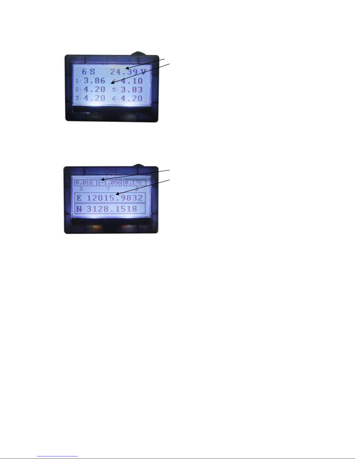
3.3.5 Экран-3
Total Voltage
Voltage for each cell
*note: this screen would only be shown if FLVS-01 sensor is connected. Otherwise, Screen-4 would
follow Screen-2 directly.
3.3.6 Screen-4
Acceleration X/Y/Z
Longitude & Latitude (GPS-data)
 Loading...