

FrSky E-Soar Setup Manual
Copyright © Michael Shellim
E-Soar
for FrSky Taranis and Horus
Version 2.0
Setup Guide
Mike Shellim
8 Feb 2017

Page 2 rev 2.0.01
Contents
1 Introduction .................................................................................................... 3
1.1 Package contents ..................................................................................... 3
1.2 Requirements .......................................................................................... 3
1.3 Nomenclature .......................................................................................... 3
1.4 Flight modes ............................................................................................ 3
1.5 Mixers ...................................................................................................... 4
1.6 Stick and switch assignments .................................................................. 4
1.7 Channel assignments ............................................................................... 4
2 Operational Overview ..................................................................................... 5
3 Motor operation ............................................................................................. 5
3.1 Arming the motor .................................................................................... 5
3.2 Running the motor .................................................................................. 5
3.3 Disarming the motor ............................................................................... 6
3.4 Motor safety ............................................................................................ 6
4 Flight Timer ..................................................................................................... 6
5 CAL mode ........................................................................................................ 6
6 Setting up your transmitter ............................................................................ 6
6.1 Preparation .............................................................................................. 7
6.1.1 Transfer files to transmitter ..................................................... 7
6.1.2 Stick calibration ........................................................................ 7
6.1.3 Control remapping (X9E & Horus) ........................................... 7
6.1.4 Familiarisation .......................................................................... 7
6.2 Calibrating the servos .............................................................................. 8
6.2.1 Prepare for calibration ............................................................. 8
6.2.2 Set servo rotation..................................................................... 8
6.2.3 Calibrate servo end-points and centres ................................... 8
6.2.4 Backup your EEPROM ............................................................ 10
7 Configuring inputs and mixing ...................................................................... 11
8 Motor safety check ....................................................................................... 13
9 Summary of in-flight adjusters ...................................................................... 14
10 Customisations .............................................................................................. 14
10.1 Changing the assignments of Spoiler and Flap ...................................... 14
10.2 Changing the flight mode switch ........................................................... 14
10.3 Reversing the spoiler stick ..................................................................... 14
10.4 Reversing flap lever ............................................................................... 15
10.5 Rates ...................................................................................................... 15
10.6 Altering minimum SH duration for motor arm/kill ............................... 15
10.7 Adjusting spoiler deadband ................................................................... 16
11 Pre-flight checks ............................................................................................ 16
12 Applying your own modifications ................................................................. 16
13 Disclaimer ...................................................................................................... 16
14 Contact .......................................................................................................... 16

Page 3 rev 2.0.03
1 Introduction
E-Soar is a full-feature setup for electric-powered gliders with 4 servos in the wing. It contains all the
mixing needed for F5J competition, yet is easy to configure and operate. Key mixers may be adjusted in
flight and an integrated flight timer is included. Special attention has been paid to motor safety with a
simple and secure motor arming system.
Please look at the Support page for any known issues which may affect your setup.
Please read through the instructions once carefully before starting.
Make sure the motor is disconnected during setup.
1.1 Package contents
Filename
Description
esoar_20_SetupGuide.pdf
Setup guide
esoar_20_SettingsRef.xls
Settings reference
esoar_20x.eepe
EEPROM images for V- and X/T- tail
esr_*.wav
Sound files
1.2 Requirements
The following will be required:
FrSky Taranis or Horus transmitter
OpenTx version 2.1, 2.2 (see change log for recommended versions)
OpenTx Companion + USB cable.
Familiarity with the OpenTx’s menus and data entry.
1.3 Nomenclature
US and UK modellers seem to use slightly different terms, and this occasionally causes confusion. For my
friends in the US, please note the term ‘spoiler’ means the same as ‘crow’.
1.4 Flight modes
There are 4 flight modes: Power, Landing, Thermal, and Cruise. In the event of a clash, Power has highest
priority, then Landing, then Cruise and Thermal. Changes in flight mode are accompanied by a voice alert.
Flight Mode
OpenTx ID
Activated by
Priority
Power
FM2
SA↑
High
Landing
FM3
Throttle stick ↓
Mid
Cruise
FM4
SA ―
Low
Thermal
FM0
SA ↓
Low
A special CAL flight mode (FM1) is provided for calibrating the control surfaces.

Page 4 rev 2.0.03
1.5 Mixers
The table below shows which mixers are active in each flight mode. Mix adjusters are in brackets.
Flight
mode
Ail→
Flap
Ail→
Rud
Motor
Spoiler
(Crow)
Spoiler
comp
Rev
diff
Camber
Diff
Power
Y Y Y
Y(RudTrm)
Landing
Y Y Y Y(Thr trm)
Y Y(RudTrm)
Cruise
Y Y
Y(RudTrm)
Thermal
Y Y Y (RS)
Y(RudTrm)
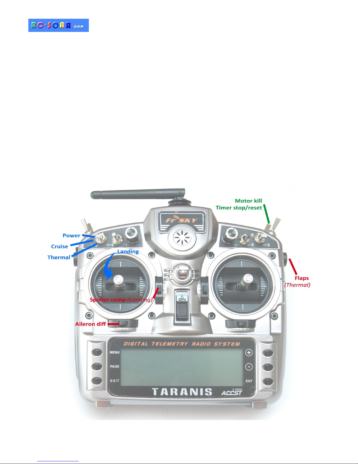
1.6 Stick and switch assignments
Stick assignments (mode1-mode4) are set in MODEL SETUP→STICK MODE.
Functions are assigned as follows:
Control
Function
Throttle stick
Spoiler
Throttle trim
Spoiler compensation adjust (Landing mode)
Rudder trim
Aileron diff adjust
SA
Flight mode selector / motor
RS
Flap adjust (Thermal mode)
SH
Cancel CAL mode
Stop/Reset timer
Disarm motor
1.7 Channel assignments
Channel #
Function
1
Right aileron
2
Left aileron
3
Right flap
4
Left flap
5
Elevator
RtVee
6
Rudder
LtVee
7
Motor
8
[free]
9
[free]

Page 5 rev 2.0.03
2 Operational Overview
Flight trims
Aileron trim is shared across all flight modes
Elevator trim is independent for each flight mode
Rudder and throttle trims are repurposed for other functions (see below)
Camber mix
Camber of flaps and ailerons is adjustable via RS (Thermal mode only)
Spoiler compensation (spoiler to elevator)
Spoiler compensation is a variable mix which compensates for pitch changes as spoiler is deployed.
The amount of compensation can be adjusted during flight, via the Throttle trim.
Non-linear compensation may be specified via curve ‘SpComp’.
Differential
Diff is applied to ailerons and flaps
Diff is adjustable via the Rudder trim.
Diff settings are stored per flight mode.
Roll rate enhancement
Aileron diff reduces to zero as spoiler is deployed. This helps with roll response under crow.
An adjustable ‘Reverse diff’ mix further improves roll response under braking.
Aileron to rudder
Aileron to rudder mix is stored individually for each flight mode.
3 Motor operation
3.1 Arming the motor
The motor is disarmed by default. To arm the motor:
1. Switch SA↓ or ―
2. Apply full right-aileron & full up-elevator, and hold
3. Pull SH and hold for 1 second until the startup sound
4. Release SH
5. Release stick(s)
A warning beep sounds every 12 seconds to indicate that the system is active.
3.2 Running the motor
Switch SA↑ to select Power mode:
If the system is armed, the motor will run at full power.
If the system is not armed, a “motor disabled” alert sound. Power mode is still active even though the
motor is not running.
 Loading...