

Page 1
Encore!
USER GUIDE
Page 2

YOU’RE ABOUT TO MAKE
LEARNING MORE ACCESSIBLE
Welcome to Encore! v1.5.5.10
Encore! is a Windows application that is designed to allow you to
easily control, or test, remote devices connected to your computer via
RS-232 serial interface or TCP/IP socket connection. Remote devices
may include projectors, video walls, video processors, or virtually any
other device which can accept commands through either an RS-232
serial port or TCP/IP socket connection.
Encore! lets you create a custom user interface, complete with
buttons, background images, and more, simply by dropping the
buttons onto the Encore! window and then assigning what you
want these buttons to do. No programming is necessary. Clicking
on the buttons sends commands to the connected devices to have
them perform some action, such as turning on or off, selecting
input, starting playback, and so on. Commands can also be sent at
scheduled times, on all or selected days.
Page 3

Contents
Install Encore! 1
Register Encore! 2
Web Registration 3
Run Encore! 4
Running with Command Line
Arguments 5
What’s New 6
Getting Started 7
Devices and Profiles 8
The Menus 9
Monitoring Communications 12
Socket Monitor Window 13
Tutorial 14
Property Editor Window 15
Creating User Interfaces 33
Property Editor 34
Adding Controls 37
Moving Controls 38
Sizing Controls 39
Deleting Controls 40
Arranging Controls 41
Control Types 42
Grouping Buttons 44
Grid Controls 45
Amplifier Control 48
Linking Controls 50
Meter Control 51
Positioning the Window 52
No Menu Mode 53
No Border Mode 54
Full Screen Mode 55
Transparent Mode 56
Creating Actions 58
Action Window 59
Action List 62
Creating a New Action 63
Devices and Profiles 65
Profile and Device Editor 66
Adding and Editing Profiles 67
Managing Devices 68
Using the Import Wizard 69
Adding a New Computer 72
Creating a Special Action 74
Grid Commands 85
Startup Actions 92
Receive Actions 93
Creating Receive Patterns 97
Import and Export Actions 98
Scheduling Actions 100
Editing a Scheduled Action 101
Managing Computers 102
Network Command Interface 105
Page 4

Contents (cont.)
Amplifier Control 106
Execute Application 107
Stop Application 108
Change Page 109
Control LED 110
Set Control Property 111
Change Profile 112
Control Window 113
Display Message 115
Execute Actions 116
Control Properties 117
Common Properties 119
Specific Properties 121
Options 123
General Options 124
Layout Options 126
Monitor Options 128
Defaults Options 130
Serial Communications Defaults 132
Whitelist Options 133
Licensing and Updating Options 134
Appendices 135
Date and Time Formatting 136
Sound Editor 137
Saving for Encore! Mac 138
Update Action 139
Page 5

Install Encore!
Your first step is to install the Encore! software onto the computer that will run it. This is typically the
teacher’s computer in the classroom.
Go to: http://gofrontrow.com/files/software/Encore_setup_v1.5.5.10.exe
to download the Encore software. Then, follow the instructions for an easy installation.
License Encore!
If you are installing Encore! for the first time, and you haven’t previously entered a registration key,
Encore! will run in trial mode. The application is fully functional but you will see occasional pop-up
windows that encourage you to buy a license. You will have to close this window in order to continue
working with Encore!. Purchasing a license will remove the pop-up windows and allow you to run Encore!
uninterrupted.
1
Page 6

Register Encore!
When you purchase a copy of Encore! you will be given a Registered Name by FrontRow. You use this
name to register your installation of Encore!, which will remove this popup registration window.
To register, press the Register Now button. This opens the window shown below where you can enter
your registered name.
Enter your Registered Name in the field, then press the Register Now
button. This will contact the FrontRow registration system, via the Internet,
and automatically register Encore!
2
Page 7

Web Registration
You also have the option of using your web browser to perform the registration. Clicking the Web
Registration button will open your web browser and take you to the FrontRow registration web site,
where you will complete the registration and receive a License Code. Once you have the code, press
the Enter License Code button and enter the code in the field provided. Once you have completed this
process your registration of Encore! will be complete.
3
Page 8

Run Encore!
The installer adds an Encore! icon to the desktop. It also installs the user manual, and a link to the
online help file. You will need
If you choose to not install the desktop icon, the Start Menu items look like this:
Adobe Acrobat to read the manual.
Select the Encore! icon to start the application.
4
Page 9

Running with Command Line Arguments
You can also start Encore! with several command-line arguments
NOMENU
The Encore! window will be displayed without a menu visible.
NOBORDER
The Encore! window will be displayed without a border, but the menu bar will be visible.
TRANSPARENT
The Encore! window will have a transparent background.
FULLSCREEN
The Encore! window will be sized to cover the whole screen and the border and menu will not be visible.
NOTE: without using one of these command line arguments, Encore! will display its window using the
Startup Mode defined in the Options dialog. The window mode is not stored in the .ccs file.
You can create a Windows shortcut icon that contains your required arguments as follows:
Make a copy of the Encore! shortcut icon that the installer made.
Right click the shortcut and select Properties from the menu.
Type the required argument at the end of the text in the Target edit box, separated from the current
contents by a space. For example,
Press OK to close the dialog.
Now, when you double click the icon, the program will be run with the arguments you specified.
Loading a Specific File:
When Encore! starts it will load the layout file Encore.ccs, if it exists. You can save a layout to this file to
have it load automatically whenever Encore! starts.
Alternatively, you can specify a .ccs file on the command line and it will be loaded when Encore! starts,
instead of the default Encore.ccs file.
The following example will launch Encore! and load a layout file called home_control.ccs:
C:\Encore\Encore.exe” NOMENU
Encore.exe home_control.ccs
5
Page 10

What’s New
This page describes the major changes available in
each product version:
Encore! v1.5.5 .
• Added tab in options dialog for
overriding settings for Licensing and
Updates. See Licensing and Updating
Options.
Encore! v1.5.4
• Added support for Mac.
Encore! v1.5.3
• Added Display Message to the special
action dialog. See Creating a Special
Action.
• Improve the meter display when using
background images.
• Improvements to copying and pasting
shape controls.
• Fix image control not properly
displaying some image formats.
• Added support for UDP messages
to the Receive Actions system. See
Receive Actions.
Encore! v1.5.1
• Added Key Press special action. See
Creating a Special Action
Encore! v1.5.0
• Added CNAP-Audio (e.g. CM-3000)
support to amplifier control. See
Amplifier Control. 〈Added ability to
receive commands from across the
network to control Encore and to add
some
• new features such as displaying a
message dialog to the user. See
Network Commands Interface.
• Added new special action to perform
an HTTP Get on a URL, which can
also be used to execute FrontRow
Conductor Trigger Scripts. See
Creating a Special Action.
• Added the ability to stream audio to
the FrontRow CM-3000.
• Added Windows theme appearance to
the button and switch controls.
See Specific Properties.
• Added new option to Control Encore!
Window special action to allow an
action to move the window so that it is
aligned to the sides and corners of the
screen. See Creating a Special Action.
• Added a new option to the Action
editor form that will treat all action
text as though it was hexadecimal. See
Creating a New Action.
• Improved the Property Editor toolbar,
and added Bring To Front and Send
To Back buttons that were previously
only available in the Edit menu.
Encore! v1.4.1
• Added new button images.
• Added confirmation option to Change
Profile special action.
Encore! v1.4.0
• Added Devices and Profiles. See
Devices and Profiles.
• Added Change Profile special action,
for use with Profiles. See Creating a
Special Action.
• Added the Computer dialog,
which allows Computer to Profile
assignments (see Assigning Profiles to
Computers), and assigning an update
filename to a computer, for use with
the FrontRow Server (see Managing
Computers).
• Added support for the FrontRow
licensing and update server.
• Added Profile and Device Import
Wizard. See Using the Import Wizard
• Added the Profile Text control, which
displays the name of the current
Profile
Encore! v1.3.4
• The streaming protocol can now be
defined, either Raw or RTP
Encore! v1.3.3
• Pages can be given descriptive names.
See The Menus
• The window transparency, whether
the menu and border are visible, and
whether the window is shown fullscreen, can be changed from within an
Action. See Creating a Special Action
• A new Special Action enables an
MP3 audio file to be streamed across
the network. See Creating a Special
Action
6
Page 11

Getting Started
This section describes the different Steps of Encore!, and how they work together. There are several key
concepts which are mentioned throughout this manual:
Actions
An Action defines a command that can be sent to a device, either through a serial port, or TCP/IP
connection. An Action typically defines a command that does a single job, such as turning a device on
or off, or selecting an input source. These commands are defined by the device manufacturer, and you
should consult their manuals to find out what commands your devices support.
Typically a command will be a text ‘string’, or sequence of letters and numbers, that the device interprets
and acts upon. Sometimes these commands contain ‘control characters’ which are not easily entered on
a keyboard, so Encore! has a simple way to select these characters from a list and enter them into the
command.
An Action also includes additional information required to send the command. For commands that are
sent out the serial port this includes the port number, speed and so forth. For network connections it
includes the network address and port.
An Encore! Action groups all this information with a descriptive name, making it easy to remember what
a command does. You can also import and export Actions to build up a library of commands for your
devices. You can also string multiple Actions together to perform multiple commands, one after another.
Encore! also has a variety of special Actions that allow you to do things like run an application, or pause
between commands.
Controls
A Control is a button or other element that can be placed on the Encore! window. You can arrange
controls on the window to provide a custom interface for your devices. Controls typically call Actions to
carry out some task. For example, you can create a button control that, when pressed with the mouse,
executes an Action to turn a device on or off. Some other controls allow you to display images or shapes,
to make your interface more useful or attractive.
Layout Design
Layout Design is the process of placing Controls on the Encore! window to create your user interface.
You can position and size the controls, change their colors, and so on. Another key task is assigning the
Actions a Control will carry out. A key Step of the process is the Property Editor window which allows you
to edit the properties (colors, fonts, Actions, etc.) of a control.
The Property Editor window is displayed only in design mode and shows the properties of the currently
selected control.
You enter design mode by selecting the Layout Design Mode item from the Tools menu. While in design
mode controls will not perform their Actions when pressed with the mouse. To exit design mode, close
the Property Editor window.
Schedules
The Scheduler allows you to schedule Actions to be done at certain times of the day, on a repeating
schedule. You could use this, for example, to turn a device on in the morning and off at night. You can
specify Actions to occur only on certain days, every day, every weekday, and so on.
7
Page 12

Devices and Profiles
Encore! Project File
Encore! stores Actions and the layout of controls in a file with the extension .ccs.
Each layout you create is stored in a separate file, so you can create as many different layouts as you
want. These files store everything that is needed to create and use the interface you have designed.
When you start Encore! it will automatically load a file named Encore.ccs, so saving your layout to a file
with this name is an easy way to have it show the same layout each time you run Encore!
NOTE: Encore! will display its window using the Startup Mode (i.e. No Menu, Fullscreen, etc) defined in
the Options dialog. The window mode is not stored in the project file.
Devices and Profiles
Devices provide a way to hold all the serial or IP settings required to communicate with a particular
device in one place. Actions can then refer to the Device rather than having the communications
settings encoded directly into the Action.
This means that if the communications settings ever change, they can be adjusted in a single location
rather than having to be adjusted in each Action individually.
Profiles is a mechanism where Encore! can switch between sets of devices, each with their own settings.
This is useful in situations where the Encore! project will be used in several locations, each with similar
equipment but with different communications settings.
Profiles allows Encore! to switch to a set of devices that match the location where it is being used. Profile
switching can be programmed into Actions, or you can be prompted to select an appropriate Profile.
8
Page 13

The Menus
The window contains the following menu commands:
File Menu
New
Starts a new project. All Actions, Controls and Schedules are cleared, so make sure you have saved your
project before using this option.
Open
Opens a project you have previously saved. The current project will be completely replaced.
Save
Saves the current project to a file. If you are creating a new project you will be prompted to enter the file
name. If it is an existing project, the current file name will be used without prompting you.
Save as
Saves the current project to a file, first prompting you for a file name. You can also save the project in a
format that can be used by Encore! for Mac (see Saving Projects for Encore for Mac).
Exit
Exits the Encore! application. If you have made changes to the project you will be asked whether you
want to save your changes.
Edit Menu
Cut
Copies the selected control to the clipboard and deletes it from the window. You can paste copies of
the control with the Paste command described below. This command is only available when in Layout
Design mode.
Copy
Creates a copy of the currently selected control on the clipboard, without removing the original.
This command is only available when in Layout Design mode.
Paste
Pastes a copy of the control that is in the clipboard (from a previous Cut or Copy) onto the current page.
This command is only available in Layout Design mode and if you have previously Cut or Copied a
control.
Delete
Deletes the currently selected Control. This command is only available when in Layout Design mode.
Bring to Front
Makes the currently selected control appear in front of any other control. This command is only available
when in Design Layout mode.
Send to Back
Makes the currently selected control appear in behind any other control. This command is only available
when in Design Layout mode.
9
Page 14

Pages Menu
This menu lists the 20 pages on which you can place your Controls. When you place controls in Layout
Design mode, they are placed into the currently selected page.
Each page is completely independent, and the Controls placed on one page are not visible when another page is selected.
Pages can be renamed, to make it easier to organize your project. When in design mode, clicking on the
window background will show a Page Name item in the Property Editor. You can change the name and
the new name will automatically appear in the Pages Menu.
The last menu item displays a sub-menu that allows you to copy the contents of the currently selected
page to another page, which you select on this sub-menu.
This is useful if you want to create a variation on a page of controls you have already designed. Copy the
current page to a different page and make whatever changes you need.
View Menu
Full Screen
Toggle the Encore! window between full screen and normal mode. In full screen mode the Encore!
window takes up the whole screen and the title, border and menu are not visible. (See Full Screen Mode)
No Border
Toggle the Encore! window between no-border and normal mode. In no-border mode the Encore!
window title, border and menu bar are not visible. (See No Border Mode).
No Menu
Toggle the Encore! window between no-menu and normal mode. In no-menu mode the Encore! window
has a border and title, but the menu is not visible. (See No Menu Mode)
Transparent Background
Toggle the Encore! window between Transparent and normal mode. In Transparent mode portions of
the Encore! window can be made transparent. (See Transparent Mode).
Tools Menu
Layout Design Mode
Changes to Layout Design mode, where you can create Controls on the Encore! window, and add, edit
and assign Actions. The Property Editor window will be displayed, giving you access to the Control
properties. Exit Layout Design mode by closing the Property Editor window. (See Property Editor)
Scheduler
Shows the Scheduled Actions window, where you can add, edit and delete Actions that will execute at
set times of the day, on the days you specify. (See Scheduling Actions)
Devices & Profiles
Opens a dialog where Devices and Profiles can be defined. It also allows Profiles to be assigned to
particular computers (See Devices and Profiles).
10
Page 15

Computers
Shows the Computers dialog which can be used to assign Profiles to Devices (see Assigning Profiles
to Computers), and to specify an update filename for when Encore! is being used with the Software
Update feature of the FrontRow Server (see Managing Computers).
Actions
Opens the Action List, where you can manage the list of actions available to your project. (see Action
List).
Monitor Port
The monitor windows are used to show the data sent out a serial port, and any data that is received by
the port. This menu has a sub-menu listing each of the possible serial ports. Select the port number of
the port you want to monitor and its monitor window will open.
The Options dialog has several options that determine how the data is presented. (See Monitoring
Communications)
Socket Monitor
Opens the Socket Monitor window, used to monitor the data sent and received through a TCP/IP
network socket. Options Opens the Options dialog, where you can change options that affect the
operation of the application. The available options are described later in this manual. (See Monitoring
Communications)
Options
Opens the program options dialog (See Options).
Help Menu
Help
Shows the Encore! help file.
Registration
Displays the dialog where you can enter your registration code to unlock the software. (See
Registration)
About
Displays version information.
11
Page 16

Monitoring Communications
You can monitor incoming and
outgoing data for serial ports,
and TCP/IP communications. The
communications for each of the 16
supported comm ports can be shown
in a separate window, while all TCP/IP
communications is shown in a single
window.
Serial Monitor Window
To open a serial port monitor, select the menu item corresponding to the port number from the Tools>Monitor Port menu. This will open a window that will display all the incoming and outgoing data. The
data display can be changed using setting in the Options dialog.
Right clicking on the window shows a popup menu where you can clear the window, copy the contents
of the window to the clipboard, and also configure the communications characteristics of the serial port.
This option displays the dialog shown to the right, and sets the port to use the settings you specify. If
you want to monitor incoming serial communications you will have to use this dialog to configure the
port to suit the communications parameters.
Port Configuration Dialog
12
Page 17

Socket Monitor Window
Socket Monitor Window
Open the TCP/IP monitor by selecting Socket Monitor from the Tools
menu. Whenever an Action sends data through a socket connection it will
be displayed in the monitor window, along with the address and port the
data was sent to. If the socket is open when a response arrives it will also
be shown in the window.
13
Page 18

Tutorial
This tutorial will lead you through the step of creating a simple button layout, to get you familiar with
how Encore! works.
Start Encore!, if you don´t already have it running, by selecting its icon from the Windows Start Menu.
We want to design a layout from scratch, so select the menu item File->New (That is the New item in the
File menu). This will give us an empty project in which we can build our layout.
Your Encore! window should now look like this:
Empty Main Window
Next, select the menu item Tools->Layout Design Mode.
You will see a new window open that will look like the one shown on the next page. This is called the
Property Editor window, and it is used to add controls to the main window, and to change the Properties
- Colors, text, etc. - of those controls.
You can only add and edit controls while the Property Editor is open. You can close the window by
clicking the red button in the top right of the window, or by choosing the File->Layout Design Mode
menu again.
14
Page 19

Property Editor Window
Initially the Property Editor displays the property for the window
background, and it enables you to change the color or place a picture in
the background.
Let’s change the background color.
Click the line that says color and you will see a button containing an
ellipsis appear at the end of that line.
Clicking the button opens the standard Windows color picker dialog:
15
Page 20

Choosing Background color
Choose a color you like and press the OK button. The Encore! window will change to that color, and the color
will also be shown in the color line of the Property Editor. Your window should look something like the image
below:
Changed Background color
Next we will change the text shown in the Encore! window title bar. Click the Window Title line in the
Property Editor. This will make the text on the right side of the line editable.
16
Page 21

Changing Window Title
Change the text to whatever you want, and you will see the main window title change:
Changed Window Title
17
Page 22

Click the Add Button button in the top left of the Property Editor - the one that looks like a small button
with OK written on it, like this:
You should see that a button has been added to the Encore! main window, and the contents of the
Property Editor window has changed:
Adding Button Control
You can move the button by putting the mouse pointer over the middle of the button, pressing and
holding the left mouse button, and dragging the mouse. The button moves to follow the mouse pointer.
When you have placed the button where you want it, release the mouse button.
Click the Add Button button again and you should see another button appear on the main window.
You can drag this control to where you want it as well:
18
Page 23

Adding a Second Button Control
The Property Editor shows the properties of the currently selected control. You can tell which control is
selected by looking for the sizing handle in the bottom right corner of the control, as shown in the image
above. When you have more than one button on the window you can only select one at a time, and this
square indicates which one it is.
Click on one button and then the other and see how the sizing handle moves between them, and how
the items in the Property Editor change depending on which button is selected. The square is also used
to resize the button but click and dragging it.
Now we will change the labels on the buttons.
Click the first button you created and then click the line labeled Label in the Property Editor. You can
now type in a new label, for example ‘On’ that will appear on the front of the button.
19
Page 24

Changing First Button Label
Do the same with the other button, entering ‘Off’ for the label:
Changing Second Button Label
20
Page 25

The Encore! main window is actually made up of 20 pages, each page containing it own controls. To see
a different page, select Page 2 from the Pages menu:
Pages Menu
You will see that the buttons have disappeared and the background has gone back to the default color.
If you click the background and then check the Property Editor, you will see the color item shows this
same color:
21
Page 26

Viewing Second Page
You can change the background color of this page just like you did with the first page above. Select
Page 1 from the Pages menu and Encore! switches back to page 1 and your buttons are visible again.
Whenever you add a new control it is added to the currently selected page, so to add a button to page
2, make sure page 2 is displayed and then click the Add Button button on the Property Editor. Pages
make it easy to group related buttons.
Now we will add functionality to the buttons:
For the purposes of this tutorial we will assume that we have Encore! connected to a device via a serial
connection on port 1. The device can accept two commands: ‘ON’ to turn it on; and ‘OFF’ to turn it off.
Both are sent surrounded by the ‘control characters’ STX and ETX (02 and 03 hexadecimal respectively).
You should consult your devices user manual for information about the actual commands it accepts.
Select the On button you created and then select the Actions line in the Property Editor.
Click the button that appears at the right end of the line, and the Action selection dialog will appear as
follows:
22
Page 27

Selecting Actions Property
The list on the left shows all the available Actions, currently there are none, the list on the right shows
that Actions that the button will perform. To add an action, click the + button on the left. This opens the
Action Editor dialog:
23
Page 28

Action Editor
Firstly we need to give this action a name. It is best to give an action a name that describes what it does,
so it is easy to recognize later. Type ‘Turn On’ (without the quotes) into the edit box.
The Action edit box contains the command to be sent to the device. The commands for our device have
to start with the control character STX.
This is a special character that is difficult to enter at the keyboard, so Encore! allows you to enter control
characters as a dollar sign followed by the hexadecimal number for the control character. So, we would
firstly enter ‘$02’ for the STX character, ‘O’ and ‘N’ for the command followed by ‘$03’ for ETX (all of the
entries do not include the quote marks).
An even easier way to enter control characters is to press the Insert ASCII button and select the
character from the ASCII Table dialog.
24
Page 29

ASCII Table Dialog
The device is connected via a serial port, so make sure the Serial Communications radio button is
selected, then select the appropriate serial parameters, in this case Port 1, Speed 9600, and the rest can
stay as the default. The window will look like the one on the next page.
25
Page 30

Serial Settings in Action Editor
Press OK to close the dialog.
You should now see the new action in the left list.
Select this item and then press the button with the arrow that points to the right.
You should see the name of the action in the right list. The button will now perform this action when it is
pressed.
26
Page 31

Selecting an Action
Click OK to close the dialog.
Do the same steps for the second button, except name it ‘TurnOff’ and use OFF for the command, not
forgetting the STX and ETX characters.
You can now try out the buttons. Close the Property Editor and then click the On button. The command
you specified is sent out the serial port - of course it wont do anything because we are working with a
hypothetical device, but you should get the idea.
Actions can also do special things like launch and application, play a sound, or change the visible page.
Open the Property Editor again from the menu. Add a new button as you did above, give it the label
‘Goto Page 2’:
27
Page 32

Adding Goto Page 2 Button
Click its Actions line in the Property Editor and click the button to open the Action dialog. Click the +
button to create a new action, name it ‘GotoPage2’ then click the Create Special button. This opens a
new dialog that is used to set up the special action.
28
Page 33

Creating Change Page Special Action
Select ‘Change Page’ from the ‘Type of Action’ drop-down list at the top of the dialog, then select 2
from the ‘Change to Page’ drop-down list.
Press the OK button.
You will see that the Action edit box now contains some text. This is in a special format that Encore!
recognizes as a special command rather than as text to be sent out a serial or TCP/IP port. This special
command doesn’t use the communications settings, so you can leave them as they are.
29
Page 34

Creating the Action
Click OK to close the dialog.
Select the GotoPage2 action from the left list and click the right arrow button to copy the action to the
right list:
30
Page 35

Assigning the Action to the Button
Press the OK button. You should now have a main window that looks like this:
31
Page 36

Main Window with Goto Button
Next, close the Property Editor and press the ‘Goto Page 2’ button. Your buttons should disappear as
Encore! displays page 2. If you changed the background color of page 2 above you should recognize it.
You can also verify which page is being displayed by looking to see which page has a tick next to it in the
Pages menu.
You can change back to page 1 by using this menu.
Of course you could add a button to page 2 and set it up to change to page 1, just like you have just
done for the ‘Goto Page 2’ button.
Hopefully this has given you a taste of what you can do with Encore!. The sections below have more
detailed information about the Encore! features, dialogs and controls.
32
Page 37

Creating User Interfaces
To create or edit an interface you must put Encore! into design mode by selecting the Design Layout
Mode
While you are in Layout Design mode the normal operation of controls such as buttons are suspended.
Clicking a button will not execute its Actions, rather it will select it and show the properties of the button
in the Property Editor.
Exit design mode by closing the Property Editor window, or by selecting the Design Layout Mode
menu item again.
item in the Tools menu. The Property Editor window will appear.
33
Page 38

Property Editor
The Property Editor shows the properties of the currently selected control - the selected control is
the one that shows a small square in its lower right corner, as shown on the button below:
Selected Button
Properties represent Steps of a control that can be changed to alter their appearance and behavior.
The toolbars at the top of the window are used to add controls to the window.
34
Page 39

Property Editor Window
Control properties include things like:
• The text shown on a button.
• The color and font of a text label.
• The Actions a button will execute when pressed.
• A sound a button will play when pressed.
• An image that shows in the window background.
You can see a complete list of the properties of each control type in the Control Properties section of
this manual.
Each line of the Property Editor represents a property you can change. The left side of each line shows
the property name, the right side the property value.
You change a property value by clicking the value. Depending on the type of the property, you can edit
is as follows:
Text Properties
These include items such as Label and Name. When clicked the right side of the line becomes an edit
box where you can edit the text. The new value is automatically accepted as you type.
35
Page 40

color Properties
Clicking a color property value will display a button containing an ellipsis (…) at the right end of the line.
Click the button to open a standard Windows color dialog where you can select a new color.
Action Properties
Clicking an Action property value will display an ellipsis button at the right end of the line.
Click the button to open the Actions dialog to set up the Actions for the property.
Number Properties
Number properties, such as Left, Top, Width and Height, work the same way as text properties, except
you can only enter numbers, not letters.
Font Properties
Clicking a font property value will display an ellipsis button at the right end of the line. Click the button
to open a Font dialog where you can select a different font.
Sound Properties
Clicking a sound property will display an ellipsis button at the right end of the line. Click the button to
open the Sound Editing dialog, where you can select a new sound.
Hotkey Properties
When a hotkey property is clicked, the right side of the line becomes an edit box. Press a key
combination (one or more of Shift, Alt, and Ctrl plus a number or letter key) to define the hotkey.
You can display the properties of the main window background in the Property Editor by clicking a clear
area of the Encore! window. Remember that the Encore! window is made up of 20 pages and each page
can have its own properties, so, for example, you can set a background picture on one page and a color
on another.
When you add a control to the window it is added to the currently displayed page, so make sure you
have the correct page selected before adding the control.
Toolba r s
The toolbars at the top of the Property Editor are used to add controls to the window. See Adding
Controls for descriptions of the available buttons.
There are four other buttons, which mirror the functions in the Edit menu:
Cut
Copies the currently selected control into the clipboard and then deletes the original.
Copy
Copies the currently selected control into the clipboard.
Paste
Pastes the control previously placed on the clipboard using Cut or Copy, back into the window.
Delete
Deletes the currently selected control.
36
Page 41

Adding Controls
You add a control, such as a button, to the current layout by using the buttons at the top of the
Property Editor window.
When you click one of the buttons the new control is added to the top left of the Encore! window, and it
becomes the active control.
The available controls are described in the Control Types topic.
37
Page 42

Moving Controls
Move a control by placing the mouse cursor over the center of the control, pressing and holding the left
mouse button, then dragging the mouse to move the control.
A small hint window appears next to the mouse pointer to show the position and size of the control,
updated as you move it.
You can also position a control by typing values into its Left and Top properties.
By default the positioning uses a grid, which makes it easier to line up controls. You can change the grid
settings in the Options dialog.
38
Page 43

Sizing Controls
Some controls, such as the Button and Switch can be resized. Only those controls that have a Width and
Height property can be resized.
Click and hold the left mouse button on the small square in the bottom right corner of the selected
control and drag the mouse to resize.
If the mouse cursor shows a circle with a cross through it when it is over the sizing square, the control is
not resizable.
You can also resize a control by changing its Width and Height properties in the Property Editor.
By default the resizing a control uses a grid, which makes it easier to make controls the same size.
You can change the grid settings in the Options dialog.
39
Page 44

Deleting Controls
Select the control you want to delete and press the Delete button on the Property Editor, or select
Delete from the Edit menu.
40
Page 45

Arranging Controls
You can stack controls on top of one another. For example, placing a rectangular Shape control under a
Text Label control would give the effect of a label sitting on a colored tile.
When you add a new control it will appear on top of any other existing control, but you can rearrange
the layering of the controls using the Send to Back and Bring to Front items in the Edit menu. Select the
control you want to effect and select the menu item to change its layering.
41
Page 46
Control Types
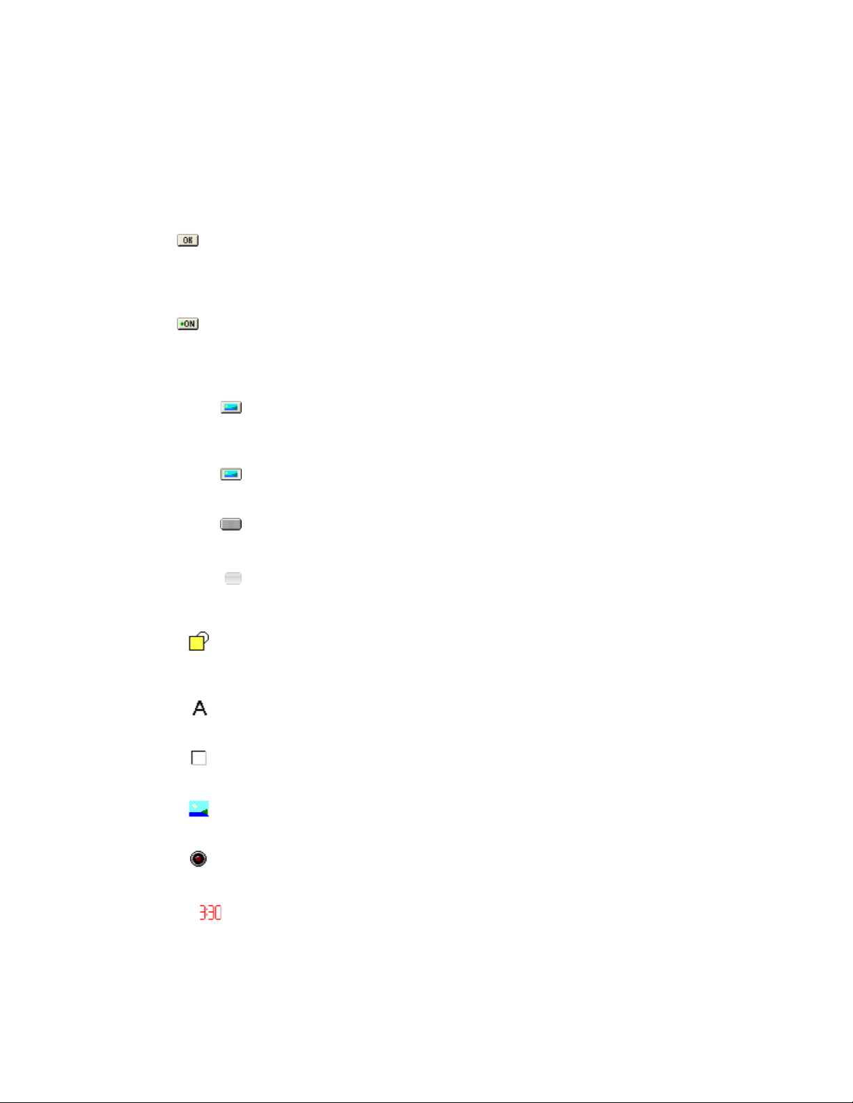
Encore! has a large number of different controls that can be added into a layout to create your interface.
Each control type has an associated button in the property editor toolbar.
Clicking these buttons adds a new control of that type to the layout.
Button
Pressing this button adds a new button. This type of button has a text label, and you can change the
color and font of the label, and the color of the background. The button can execute a set of Actions
when pressed with the mouse.
Switch
This is similar to the Button but behaves like a switch. Press it once to turn the switch on, and again to
turn it off. The Switch can perform one set of Actions when turning on, and a different set when turning
off.
Bitmap Button
The Bitmap Button works like a button, but displays an image you specify instead of using a standard
button image. This enables you to make buttons look however you want.
Bitmap Switch
This is a Bitmap Button that works like a Switch.
Metal Button
This control can work like either a button or a switch, and has a metallic look.
Glass Button
This control can work like either a button or a switch, and has a glass look, which can be changed to
several different colors.
Shape
The Shape control draws a simple shape - square, rectangle, ellipse, etc. - which can be drawn in a
specified color.
Tex t Label
This control displays a text label using a specified font and color.
Bevel
Displays a 3D border that makes the area inside it seem to pop out or in of the screen.
Image
Displays an image.
LED
Displays a light emitting diode which can be turned on, o, or set to blink.
Digital Clock
Displays a text area containing a digital clock. It can display the date and/or time, using a format
you specify.
42
Page 47
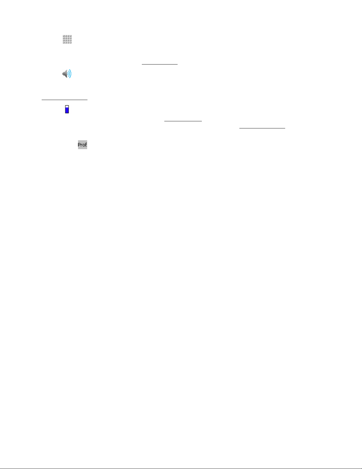
Grid
Creates a grid, or matrix, of buttons that stay together in a group. The buttons in the grid can be used
like normal buttons, or can be combined with the Grid Command special action to create complex
command messages. See the section Grid Controls for detailed information.
Amp
The Amp control makes it easy to control a FrontRow amplifier. You can use simple commands like
‘Set Volume’, ‘Mute’ and ‘Set Channel’, instead of using the cryptic serial commands. See the section
Amplifier Control for detailed information.
Meter
The Meter control is a level meter display (see Meter Control), and it is usually used together with the
Amp control to display an amplifiers current volume level. (See the section Amplifier Control for detailed
information).
Profile Text
Creates a text label that shows the Profile current in use.
43
Page 48

Grouping Buttons
Buttons that can act like switches can be grouped together. Only one button in the group can be
switched on at any time. When you click a button any other button in the same group that is currently
turned on, will automatically be turned off. Groups are useful for creating things like source selectors
(like on a stereo), where only one source can be selected at any time.
The types of controls that can used groups are Switches, Bitmap Switches, and Metal and Glass buttons
Their
Is Switch property is set to Yes. Grouping only works between switches of the same type, so
Glass buttons can only be grouped with other Glass buttons, for example.
To create a group of buttons, simply enter a group name in each of the buttons Group property (in the
Property Editor). The Group ‘name’ can be anything you like - text or a number. All buttons of the same
type that have the same group name will be in the same group.
44
Page 49

Grid Controls
The Grid control is an advanced control that can either work like a collection of buttons, or can work
with the Grid Command special action to create complex actions.
You add a Grid to an Encore page using the Grid button ( ) on the Property Editor. This
adds a default grid, as shown below:
A New Grid Control
You can see that the Grid is made up of 4 rows, and 4 columns of buttons. You can change the number
of buttons in the Grid by altering its Rows and Columns properties.
You can also display a large number of buttons in a small space using the Pages feature. By default there
is only one page of buttons in a grid, so the total number of buttons is calculated as ‘Rows x Columns’
buttons. If you set the Grids Pages property to greater than 1, the total number of buttons is calculated
as ‘Rows x Columns x Pages’. You will also see that two additional buttons will appear at the bottom
of the Grid. These are used to move backwards and forwards through the pages of buttons. The two
images below show the same Grid, the first using a Pages setting of 1, the second a Pages setting of 2
Grid With Pages of 1
Grid With Pages of 2
You can see the two buttons at the bottom of the second Grid. You can change the text shown on these
buttons using the ‘Label for Previous Button’ and ‘Label for Next Button’ properties.
Note that the Grid Pages are completely separate from the Encore Pages feature. The Grids pages are
internal to the Grid.
The grid can be positioned like any other control. Its size is determined by the number of Rows and
Columns, and the size of the individual buttons. The button size can be changed using the ‘Button
Width’ and ‘Button Height’ properties.
45
Page 50

The Grid control has a property called ‘Editor’ that allows you to access the settings for the Grid
buttons. Select the ‘Editor’ property in the Property Editor, then click the ellipsis button. This will
open the Grid Editor dialog:
Grid Editor Dialog
The ‘Mode’ drop-down box defines how the buttons in the grid operate. There are three possibilities:
Button Mode
The buttons work like normal Encore! buttons. You can assign different Actions to each button, as
described below.
Single Switch Mode
The buttons work like switches - they toggle on and off as you press them. The buttons do not have
normal Actions assigned to them, but rather have a value that is used in conjunction with the Grid
Command special action to produce complex commands. The Single Switch mode allows only one
switch to be turned on at a time.
Multiple Switch Mode
This is similar to the Single Switch Mode, but it allows more than one switch to be turned on at a time.
Button Mode buttons work just like other Encore! buttons, but the two Switch Modes are quite
different. When you press a button in a Switch Mode grid, no action is performed. Instead, Encore!
46
Page 51

just remember the value assigned to the button (see below) and can then use it when you perform a
Grid Command special action. You should see the section on Grid Commands for more information.
Editing Buttons
You can edit a button by selecting it in the Grid Editor list, and clicking the Edit button, or by doubleclicking a list item. This opens the Grid Button Editor, from which you can change the label shown on
the button, and edit the Actions (for Button Mode), or Value (for the Switch Modes) assigned to the
button. The image below shows a Button Mode button being edited.
Grid Button Editor
If you are editing a button in a Switch Mode grid, the Actions entry box will be replaced with a Value
edit box, where you can set a Value for that button.
If you have the Grid set to either of the Switch Modes, you will see an additional ‘Range’ button
in the Grid Editor window. This allows you to set a range of values across multiple buttons. Select
more than one button in the Grid Editor list box, then click the Range button. You will see the Range
Editor dialog:
Range Editor
The Range Editor will assign a value to each of your selected buttons in turn. The first will get
the value of Start Number, the second the Start Number plus the value of Increment, and so on.
‘Minimum Number of Digits’ specifies a minimum length for the value. Any numbers shorter than
this value are padded with zeros.
For example, the values:
Start Number: 1
Increment: 2
Minimum Number of Digits: 3
Would give values: 001, 003, 005, 007, ...
47
Page 52

Amplifier Control
The Amp control makes it easy to control a FrontRow Amplifier, changing the channel or volume, etc.,
without having to learn the amplifiers communications commands. The Amp control also maintains a copy
of the amplifier status (volume, channel and mute state). It can periodically poll the amplifier to update its
status in case the amplifier has been changed by another copy of Encore!, or some other application (such
as through the web browser interface).
You can use the Amp in conjunction with other controls, using their Link properties, to display the current
status of the amplifier. You can, for example, use the Meter control to display the current volume setting,
or use a switch button to display the mute state.
The Amp control can control both the serial-based FrontRow CA-1000 amplifier, and the network-based
CM-3000. CA-1000 amplifiers are always controlled through a FrontRow controller, such as an ION-LT2.
The amp must be connected to the controller via its RS-232 serial port.
Encore currently only supports having a single amplifier connected to each controller. You can control an
number of amplifiers so long as they are connected to separate controllers.
An Amp control is added to the Encore! layout just like other controls, by clicking its button
Adding An Amp Control
on the Property Editor toolbar. The Amp will appear on the Encore window, however it does behave
differently than other controls. Firstly it will only be visible when in Layout Design mode. As soon as you
exit the design mode the Amp control will be hidden. It will re-appear when you go back into design
mode. This is because the Amp is not a control for the end-user, like a button is, but rather it provides
control for the designer. The second difference is that it will appear, in design mode, no matter which
Page is showing. This just makes it easier to use, because you do not have to remember which page you
dropped it on, and since it is not visible outside design mode, it does not need to be on a specific page.
When you select the Amp control on your Encore! window you will see it has properties in the Property
Editor, just like any other control. These properties are:
Name
A name for the control. Giving it a distinctive name makes it easier to use in Commands and Linked
controls.
Amp Type
Specifies the type of Amp you will be controlling. The choices are CA-1000 and CNAP-Audio (which is a
standardized control set for FrontRow network based audio, and includes the CM-3000).
Left, Top
The position of the control on the Encore! window. Since this control is not visible to you, these are only
so you can place it where you want it to make it easy to locate.
COM Port
Specifies the serial port on the controller that the amplifier is connected to. The controller will be told to
send commands out this serial port. When Amp Type is set to CNAP-Audio the COM Port is ignored,
since all communications are network-based.
IP Address, IP Port
For CA1000’s this specifies the address and port of the controller that the amplifier is connected to. The
Amp control will send commands to the amplifier via this controller. For Amp types of CNAP-Audio this
is the IP Address and Port of the audio device (e.g. CM-3000).
48
Page 53

IMPORTANT: These settings are only used if the All Actions use these defaults setting in the
Options dialog is turned off, otherwise they are overridden by the default settings. The Amp will also
use the Close After Sending and Wait For Response settings in the Options dialog.
Poll Interval
Specifies how often the Amp control will request status information from the amplifier, in milliseconds.
The more often the polling is done the more up-to-date the status will be, but the higher the network
traffic will be. Also keep in mind that while the amplifier is processing status query commands it cannot
react to other commands. You can disable polling by setting this to zero.
Controlling an Amplifier
Once you have added the Amp control, and set its properties, you can send commands to the Amp.
You can set up Actions to make it:
• Increment the volume
• Decrement the volume
• Set the volume to a specified level
• Mute all channels
• Un-mute all channels
• Toggle the mute on/off
• Set the output to a specified channel
• Query the volume, mute and channel status
You can then use the actions as button press actions, scheduled actions, receive actions, and so on. The
easiest way to create an Amp control action is to use the Special Action editor. The Amp control will take
care of sending the correct command to the amplifier.
You may also read the section Linking Controls for information about how to use the Linking feature to
update other controls in response to changes in the Amplifier status.
49
Page 54

Linking Controls
Linking allows a control to change its appearance in response to a change in another control,
automatically, without you having to create any special actions. For example, if we wanted to have a
meter that tracked the volume of the amplifier, we would previously have had to make a large number
of Receive Actions that changed the meter position in response to presses of volume increase and
decrease buttons. With Linking we can tell the meter to watch the volume level of the amplifier and the
meter will change when the volume changes.
Currently, the only control that can be linked to is the Amp control. It allows other controls to react to
changes in Volume, Channel, Mute and Active (whether the amplifier is responding to commands). The
Switch, Bitmap Switch, Meter and LED controls can monitor the Amp control and react to changes.
These four controls have a Link property, visible in the Property Editor.
When you select the Link property you will see an ellipsis button. Clicking this shows the
Link Editor
window:
Link To Control
project. When you select an Amp you will then be able to select a Property, which is the property of
the Amp that you want the current control to monitor.
The properties that are available will depend on the type of control Link you are editing:
LED Control. This can react to the Mute and Active property. The LED will turn on when the
amplifier is muted, or when it is active (the amp is inactive if it is not responding to commands).
Switch and Bitmap switch: These react to the Mute and Active properties. The switches will be
pressed down when the amplifier is muted, or when it is active.
is the control that should be monitored. It is a drop-down list of Amp controls in your
Meter: This reacts to Volume and Channel properties. As the volume or active channel changes, so
does the meter display. See the Meter Control section for more information on the meter.
Once you have selected the Amp and property to monitor, click OK. The control you are editing will
now react to changes in the amplifier status automatically. Note that once you have set up a controls
Link property, that will override the normal operation. If you attempt to alter display of the control using
normal Actions, you might get strange results.
NOTE:
different Meter on each page, each displaying the volume of the amplifier.
If Encore! cannot communicate with the amplifier, either because it is not connected to the controller, or
the controller itself is not responding, the Active property will be turned off. This enables you to have a
control, such as the LED show when the amplifier is available.
You can have more than one control linked to the same Amp. You could, for example have a
50
Page 55

Meter Control
The Meter control shows a value in a level meter style. As the meter Position, or value, changes the
meter adjusts to show the value as a proportion of its display area.
The meter can be displayed horizontally or vertically, and can be customized to change its appearance.
The meter can also use the Linking feature to display the status of an amplifier. You can also control the
meter manually by using the
meter.
The meter is added to your project by pressing the Meter button on the Property Editor toolbar.
When you select it you will see a number of properties in the Property Editor:
• Name: Gives a descriptive name to the meter.
• Left, Top, Width, Height: These set the position and size of the meter.
• Orientation: Sets the direction in which the meter level moves as the Position increases. If
Vertical the meter starts at the bottom and move upwards, if Horizontal the meter starts at
the left and increases to the right.
• color: Sets the color of the meter bar. This is only used if the style is set to color.
• Border color: Sets the color of the border around the meter.
• Style: Sets the style of the meter. See below for examples of the settings.
• Background color: Set the color that is not covered by the meter - the area above, or to the
right of, the Position.
• Border: Sets whether the border is shown or not.
• Bitmap: Sets the bitmap used in the Repeating Bitmap and Stretched Bitmap styles.
• Min: Sets the minimum value of the meter. When the Position is less than or equal to this
value the meter will be empty.
• Max. Sets the maximum value of the meter. When the Position is greater than or equal to this
value the meter will be full.
• Position: Sets the current position, or value, of the meter. It ranges from the Min to Max
values, and the meter fills the display as it increases.
• Link: Sets up a link to an Amp control, to automatically display a value such as the Volume.
See the Linking section for more information.
Styles
The image below shows some of the different styles you can use.
The first meter shows the color style, which draws the meter in a single color. The next three meters use
the image labeled ‘Bitmap 1’ in different ways.
The first and second show the meter set to Repeating Bitmap. As the position of the meter changes,
from the first meter to the second, the bitmap is revealed.
The next uses the same image, but it uses the Stretched bitmap style. With this style the entire bitmap
image is stretched or shrunk to be fit into
the current position of the meter.
The last two examples use the bitmap
labeled ‘Bitmap 2’. The first uses the
‘Stretched Bitmap’ style, which has
stretched the small bitmap to fit the meter.
The second uses the ‘Repeated Bitmap’
style, which repeats the small bitmap to fill
the meter.
Set a Controls Property special action to control the position of the
51
Page 56

Positioning the Window
The size and screen position of the Encore! window is stored in the project file, so when it is opened it will
be in the same place, and with the same size, as when you last saved the project.
You can set the size and position of the window either using the mouse, just like you would any window
in a Windows application, or you can set it numerically in the Property Editor. When in design mode, click
the background of the Encore! window and the property editor will show the properties for the window.
The
Window Left, Window Top, Window Width and Window Height properties determine the
size and position of the window.
Aligning the Window to the Screen
An alternative way to position the Encore! window is to align it with the edge of the screen. When the
project is opened the window will appear relative to the edge of the screen. The advantage of this is that
the Encore! window will appear in the same relative position no matter the size of the screen where your
Encore! project file is being used. A window aligned to the Top-Right of the screen will appear in the topright no matter what the resolution of the screen.
You set the alignment using
the window Alignment
property. Clicking on
the ellipsis button that
appears when you select
the Alignment property
will show the Window
Alignment editor shown
below:
Alignment Property Editor
Click the button next to the area of the screen where you want the Encore! window to appear, or click No
Alignment
if you want to disable the alignment feature.
NOTE: the window will only be positioned at the chosen location the next time the project is opened.
When alignment is active you can also push the window away from the edge of the screen, creating a gap
between the window and screen edge.
Use the Horizontal Padding and Vertical Padding properties to specify the size of the gap (in pixels).
The Horizontal Padding specifies the gap between the left or right edges of the window and the left or
right edges of the screen, the Vertical. Padding does the same for the top and bottom edges.
52
Page 57

No Menu Mode
You can hide the Encore! window Menu bar in several ways:
Use the No Menu item in the View menu. (See The Menus) Press the keys Ctrl+M to toggle the menu on
and off.
Select the No Menu Mode item from the Startup Mode drop-down list in the Options dialog. (See
General Options)
Use the command-line argument NOMENU. (See Running Encore!)
The image below shows an example window with the Menu hidden.
No Menu Mode
53
Page 58

No Border Mode
You can hide the Encore! window border, including the menu bar in several ways:
Use the
border on and off.
Select the No Border Mode item from the Startup Mode drop-down list in the Options dialog.
(See General Options)
Use the command-line argument NOBORDER. (See Running Encore!)
The image below shows an example window with the border hidden.
No Border item in the View menu. (See The Menus) Press the keys Ctrl+B to toggle the
No Border Mode
54
Page 59

Full Screen Mode
You can make the Encore! window cover the entire screen area:
• Use the
• Press the keys Ctrl+F to toggle the full screen on and off.
• Select the Full Screen Mode item from the Startup Mode drop-down list in the Options
dialog. (See General Options)
• Use the command-line argument FULLSCREEN. (See Running Encore!)
Full Screen item in the View menu. (See The Menus)
55
Page 60

Transparent Mode
Transparent Mode allows you to make Steps of the Encore! window transparent, so windows from other
applications and the Windows desktop show through. The transparency works by designating a specific
color as transparent. When you create a background image to load into Encore! you use that color
everywhere you want the window to be transparent. Any other color will be opaque.
You put Encore! into Transparent Mode in several ways:
• Use the Transparent item in the View menu. (See The Menus)
• Press the keys
• Select the Transparent Mode item from the Startup Mode drop-down list in the Options
dialog. (See General Options)
Use the command-line argument TRANSPARENT. (See Running Encore!)
Once the window is transparent you can drag the Window by clicking and holding the mouse button
when the cursor is over a non-transparent Step of the window. You can then drag the mouse to move the
window.
By default the transparent color is purple, but you can change that in the Layout section of the Options
dialog. When creating your background images you must use the exact color, with the same Red, Green
and Blue values. You should also save the images in an uncompressed format (BMP, PNG, TIFF)
because in a compressed format like JPEG, the compression process can alter the colors and so the
transparency effect may not work correctly.
If you loaded the
image below into
the Encore! window
background, and
turned on Transparent
mode, the purple
areas would become
transparent, but the
yellow ellipse and blue
rectangle would remain
opaque. You can place
controls anywhere
on the background,
they don’t just have
to be on the opaque
areas. In fact, if you
switch to transparent
mode without loading
a background image
the whole window will
become transparent
and you will only see
the controls.
Ctrl+T to toggle the transparent mode on and off.
Examp le Image
56
Page 61
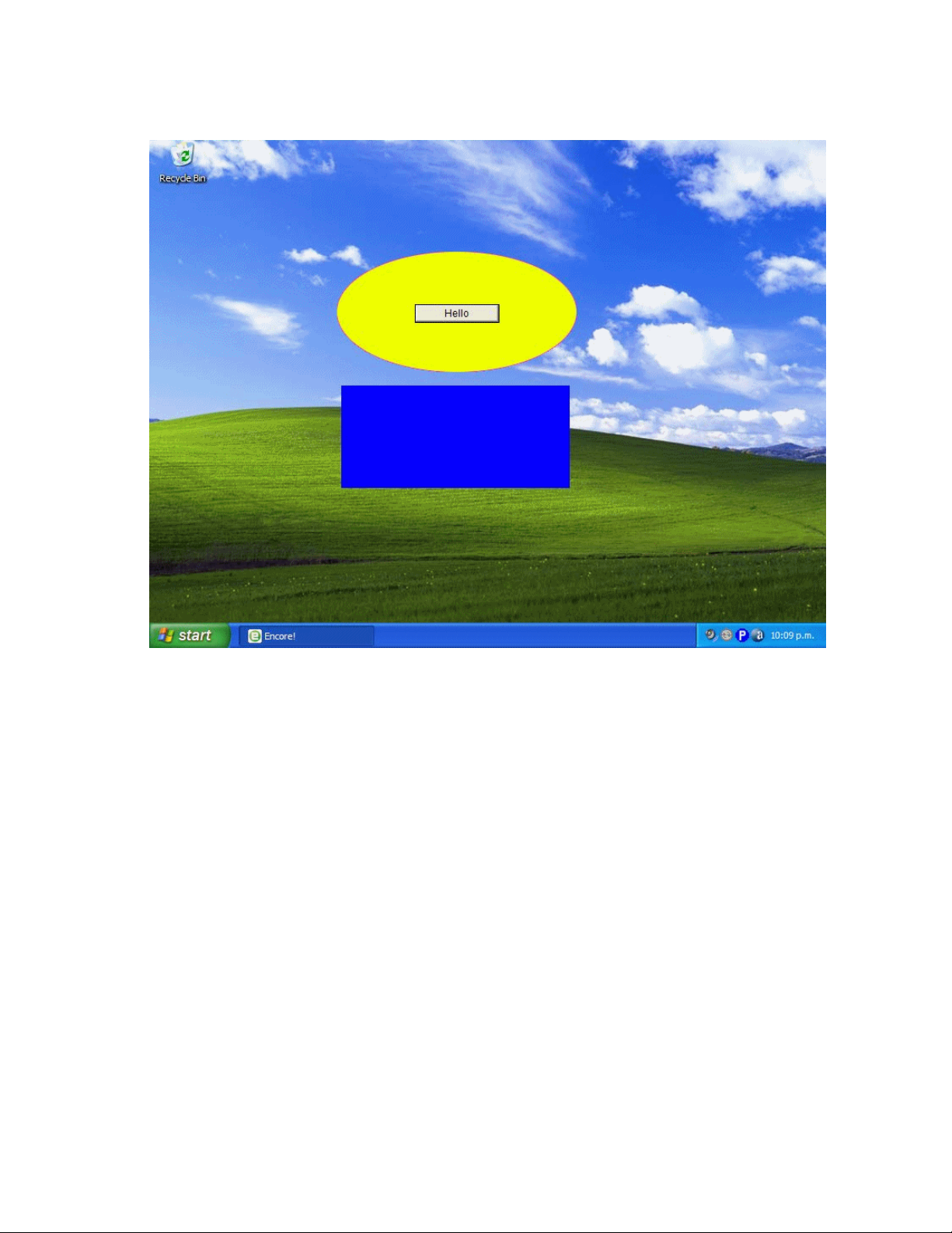
This is what this looks like when loaded into Encore!, a button added in the
middle of the ellipse, and transparent mode is turned on.
Example Transparent Background
57
Page 62

Creating Actions
Actions are created, and edited, using the Actions dialog.
The dialog is opened by selecting the Actions property for a control in the Property Editor, and pressing
the ‘...’ button that appears at the right end of the line.
For a scheduled action, click the ‘...’ button on the Edit Scheduled Action dialog.
58
Page 63

Action Window
The Action window shows all the defined Actions, and allows you to assign Actions to controls or
scheduled Actions. The window has buttons for adding, editing and deleting Actions, and also
Exporting and Importing Actions.
Actions Window
The features of the dialog are:
Available Actions List
This list shows all the Actions in your project. You can use the buttons below to add, edit and delete
Actions.
Actions For This Control
This list shows the Actions that the control will execute. When the control executes its Actions it
performs them in the order listed in this list. So for a button this would be all the Actions that are
executed when you press the button with the mouse. To add an Action to this list, select it in the
Available Actions list and press the button with the right-pointing arrow. Alternatively you can drag an
action from the Available list into this list.
Add Button
Adds a new action. The Edit Action dialog is displayed where you can set up the new Action.
Edit Button
Edits the currently selected Action. The Action is displayed in the Edit Action dialog for editing.
59
Page 64

Delete Button
Deletes the selected Action from the Available Actions list. Once an Action has been deleted you
cannot get it back, you must re-create it if you need the same Action again.
Duplicate Button
Makes a copy of the currently selected Action. This is useful if you need to create a new Action that is
similar to one you already have.
Gear Button: Pressing the button with a gear symbol on it displays a menu with the following
additional commands:
Test
Tests the currently selected Action. The Action is performed just as it would be if it was assigned
to a button.
Clear Available Actions
Clears all the items from the Available Actions list
Sort Available Actions
Sorts the list of Actions into alphabetical order.
Import
Imports Actions from a file. A file selection dialog is shown where you can select the file
containing the Actions. The Import Dialog will then be shown where you can select which of the
Actions in the file should be imported, or all chose to import them all.
Export
Exports the Actions in the Available list to a file. The Export Dialog will be shown where you can
select which Actions are actually exported, or chose to export all the Actions.
Up Button (Under the Available Actions list)
Moves the selected action higher in the list, if there is more than one Action in the list, and the selected
Action is not already at the top.
Down Button (Under the Available Actions list)
Moves the selected Action lower in the list, if there is more than one Action in the list, and the selected
Action is not already at the bottom.
Right Arrow Button
Copies the selected Action from the Available list into the Actions For This Control list.
Left Arrow Button
Removes the selected action from the Actions For This Control list.
Up Button (Under the Actions for this Control list)
Moves the selected action higher in the Actions For This Control list, if there is more than one Action in
the list, and the selected Action is not already at the top. The Action will then execute earlier when the
controls Actions are executed.
Down Button (Under the Actions for this Control list)
Moves the selected Action lower in the Actions For This Control list, if there is more than one Action in
the list, and the selected Action is not already at the bottom. The Action will then execute later when the
control Actions are executed.
60
Page 65

OK Button
Closes the dialog. If you have moved Actions into the right list they are assigned to the Action of the
Control or Scheduled Action.
Cancel Button
Closes the dialog without changing the Actions that were already assigned to the Control or Scheduled
Action.
61
Page 66

Action List
The Action List window shows all the defined Actions, and allows you to add, edit, delete, export and
import Actions.
The features of the dialog are:
Available Actions List
This list shows all the Actions in your project. You can use the buttons below to add, edit and delete
Actions.
Add Button
Adds a new action. The Edit Action dialog is displayed where you can set up the new Action.
Edit Button
Edits the currently selected Action. The Action is displayed in the Edit Action dialog for editing.
Delete Button
Deletes the selected Action from the Available Actions list. Once an Action has been deleted you
cannot get it back, you must re-create it if you need the same Action again.
Duplicate Button
Makes a copy of the currently selected Action. This is useful if you need to create a new Action that is
similar to one you already have.
Gear Button: Pressing the button with a gear symbol on it displays a menu that contain additional commands:
Test
Tests the currently selected Action. The Action is performed just as it would be if it was assigned
to a button.
Clear Available Actions
Clears all the items from the Available Actions list
Sort Available Actions
Sorts the list of Actions into alphabetical order.
Import
Imports Actions from a file. A file selection dialog is shown where you can select the file
containing the Actions. The Import Dialog will then be shown where you can select which of the
Actions in the file should be imported, or all chose to import them all.
Export
Exports the Actions in the Available list to a file. The Export Dialog will be shown where you can
select which Actions are actually exported, or chose to export all the Actions.
Up Button
Moves the selected action higher in the list, if there is more than one Action in the list, and the selected
Action is not already at the top.
Down Button
Moves the selected Action lower in the list, if there is more than one Action in the list, and the selected
Action is not already at the bottom.
62
Page 67

Creating a New Action
To add a new Action, press the Add button on the Actions Dialog. This opens the Edit Action dialog
where you set the properties of
your new action.
You must give the Action a
name, enter the data to be
sent to the device, and what
communications mechanism to
use to send the command.
NOTE: Many of the Special
Actions (see Creating a
Special Action ) do not use
the communications settings.
When you set an Action to
use a Special Action the
communications parameters
on this dialog will be hidden.
If you change the Special
Action back to a normal action
(or use a Special Action that
does use communications) the
parameters will be shown again.
The dialog has the following
fields and buttons.
Name
Giving an Action a descriptive
name makes it easier to
remember what the Action
does.
Action
In most cases this defines the string of characters that are sent out the communications port when the
Action is executed. The exception is when it defines a Special Action (see below).
You can enter any characters into the edit box and they will be sent as-is. To send control characters that
cannot be entered from the keyboard you enter a special ‘escape sequence’ that tells Encore! which
character you want to send.
To do this, enter a ‘$’ followed by the 2 digit hexadecimal number for the control character. If, for
example, you want to send the ASCII ACK character, which has a hexadecimal code of 6, you would
enter ‘$06’ into the edit box. The easiest way to enter control characters is to use the Insert ASCII button
(see below). If you need to send just a ‘$’ character then you have to enter with two dollar symbols (‘$$’).
63
Page 68

Create Special
This button is used to create special Actions that perform a task rather than send data out the
communications port. See Creating a Special Action for more information.
Insert ASCII
Opens the ASCII Table dialog where you can chose a control character to insert into your Action
command string. The table shows the Decimal, Hexadecimal and ASCII name of all the characters in the
standard ASCII character table.
Select the character you want to insert and press the Insert button. The character will be inserted into
the Action edit box, at the location of the cursor. Press the Close button if you want to close the dialog
without inserting a character.
Test
This button performs the Action you have created.
Action Text Is All Hexadecimal
If this checkbox is ticked Encore! treats all the text entered in the Action edit box as though it is
hexadecimal characters. Each characters is represented by two characters, so you need to enter an
even number of characters and only valid hexadecimal numbers are allowed (0 to 9 and A to F).
Serial Communications
To send your command out a serial port, select this radio button and set the characteristics of the serial
protocol using the Port, Speed, Handshaking, Databits, Stopbits and Parity editors. The Port is the port
on your PC you have connected the device to, and the other settings should be set up according to the
requirements of your device.
TCP/IP Socket Communications
To send your command out through a network socket connection, define the network address your
device is using, and the port it is listening on. You can use the Ping button to test whether the device is
available at the address and port you have specified. A dialog will be displayed saying whether or not
the device responded to the ping.
Encore! will usually leave a socket connection open after sending a command, and any future
communications to the same address will use the same connection. If you require the socket to be
closed between each command, check the Close After Sending check-box.
Device
Devices provide a way to centralize the communications settings for the devices you will control with
Encore!. To send the command to a Device, select this radio button and then select the device the dropdown menu.
Devices can be configured using the
the available devices by pressing the Edit button here. See the section Devices and Profiles for more
information on using Devices.
Once you have entered your command, click the OK button to return to the Actions dialog. You should
see the Action appear in the Available Actions list, using the Name you specified.
Devices & Profiles item in the main menu, and you can also edit
64
Page 69

Devices and Profiles
Devices and Profiles are useful tools for managing Encore! projects, particularly when many instances of
Encore! are being used, and where they may be used to control similar equipment in different locations
or situations.
A Device gives an easily readable name to the settings required to communicate with a particular piece
of equipment. So a device named Projector could define the RS232 settings needed to send commands
to the projector, while a device named ION-LT could define the IP parameters required to talk to a
FrontRow ION-LT control module. It is up to the designer to decide which devices to create and what
to call them. When Actions are created to control the equipment, the Device name is used rather than
encoding the communications settings into each and every Action. So, if the IP address of the ION-LT,
for example, were to change, the Encore! project can be updated by changing the IP address in one
place - the Device definition - rather than in every Action that refers to the ION-LT.
Profiles are an extension of the Device concept, and allow you to store multiple alternate settings
for each Device. Each collection of devices and their settings are given a name - the profile name
- and Encore! can change between Profiles either from an Action or via user selection. It can also
automatically select the correct profile to use based on the computer running Encore! (see Assigning
Profiles to Computers). One Profile is always the
the Devices (and their settings) that are currently being used. Every Profile has the same collection of
Devices, but the Device communications settings can be different.
As an example of how Devices and Profile can be used, consider a school that has many class rooms,
each with the same basic package of equipment - like the FrontRow ezRoom. Each room has a different
IP address for the FrontRow controller that is Step of the ezRoom. Teachers move between rooms during
the day, and want to be able to control the equipment in the room they are currently in.
Before Devices and Profiles they would either have to change the default communications settings,
which is inflexible, or have a completely separate Encore! project for each room, which quickly becomes
unmanageable. With Devices and Profiles you can define a Device for each piece of equipment (like the
FrontRow controller), and define a Profile for each room.
The Profile contains the actual communications settings for the Devices in that room. Using the Change
Profile
simply have a number of buttons, each representing a room, which, when pressed, changes the current
Profile to the selected room. Thus, all the information about the devices and their settings are kept in
the normal Encore! project, and the end-user can easily change between devices without needing to
know about IP address and so forth.
The Current Profile
There is always one active or current Profile. Encore! uses the following criteria, in order of highest to
lowest, to determine which Profile to use:
special action it is simple to either prompt you to select the Profile (i.e. the room they are in), or
current profile and it points to the Profile that defines
If you have selected a profile, or the Change Profile special action has been used to change the profile,
use that profile. If the computer has been assigned a particular profile (See Assigning Profiles to
Computers), use that profile. If a profile has been defined in the
window, use that profile.
The Profile named Default is used. You can use the Profile Text control to display the current profile on
the Encore! window. Default is a special profile in that it cannot be deleted, otherwise it is the same as
any other profile.
65
Default Profile property of the main
Page 70

Profile and Device Editor
The Profile and Device editor dialog is accessed by selecting the
menu. This displays a window like that shown below:
Profiles & Devices item in the Tools
Device and Profile Editor dialog
In this window you can see all the defined Profiles in the list on the left, and the Devices that exist in
those Profiles in the right list. As you select Profiles the Device list is updated to show the settings for
that Profile.
You can also access the function to Assigning Profiles to Computers, by pressing the Assign Profiles
button.
The Current Profile label at the bottom shows the profile that is currently in effect on this computer
-the Profile that will be used for any Action that uses Devices for their communications.
66
Page 71

Adding and Editing Profiles
The
Profiles list is used to select the Profile that is being edited.
Profiles can be Added by clicking the ‘+’ button. You will be prompted to enter a unique name for the
Profile:
Add Profile dialog
The new Profile will take its initial Device settings from the Default profile. You can then customize the
Devices to fit the use of the new Profile.
You can delete the selected profile using the ‘-’ button. The Profile named Default cannot be deleted,
and is used as the current profile if no other profile can be selected.
The gear, or action, button contains additional commands:
Duplicate
Create a duplicate of the selected Profile, with exactly the same Device settings. You are prompted to
enter a name for the new profile.
Clear
Clears all the Profile and Device information.
Sort
Sorts the Profiles into alphabetical order, although the Default profile always remains first in the list.
Import Wizard
Imports data from a comma-separated value text file. The wizard allows you to define the import format
based on the contents of your file. See Using the Import Wizard
Import XML
Import will read the Profiles and devices from an XML file that was previously saved using the Export
command.
Export XML
The Profiles and Devices are written out to a file. This is useful to move Profiles and Devices between
projects. When you select this command you will be prompted to enter a name for the file, then the data is
written.
67
Page 72

Managing Devices
The Add Device button adds a new Device to all Profiles. This opens the Edit Device dialog shown
below:
Device Editor dialog
You can enter the name of the Device, which cannot be the same as any existing device, then select and
enter the default communications settings. When you press OK a new Device with these settings will be
added to every Profile. You can then edit the Device in specific Profiles to change the settings for only
that Device & Profile.
You can edit devices by selecting them in the list and clicking the Edit button, or by double-clicking
them in the list. It is important to remember that you will be editing the device settings for the selected
Profile only.
You can delete a device by selecting it in the list and pressing the Delete Device button. The device
will be deleted from every Profile.
68
Page 73

Using the Import Wizard
The Profile Import Wizard is used to import Profile and Device information from a text file in commaseparated value format. You can import data to set up Profiles, Devices, and computer-to-profile
assignments. The wizard lets you define which fields in your file should be mapped to Profile/Device
settings, such as IP Address, Profile Name, and so on.
When you launch the Wizard from the
prompted to enter the name of your file. You can either type it in directly or use the ellipsis button to
bring up a file dialog, where you can select the file. Press Next to continue.
The wizard will load your file and display it in a grid. You must now tell the wizard what each column in
the file represents. You do this by using the drop-down list at the top of each column. Change each
drop-down list so that it matches the contents of the column. In the image below the first
column has been specified as the Profile Name, the second the IP Device Name and the third the
Profile and Device Editor action button, you will first be
IP Address. You must assign one column to the Profile Name, otherwise the wizard will not know
what the rest of the data refers to.
Profile Import Wizard: Setting Field Mapping
Press Next to begin the import process.
69
Page 74

The available data types you can assign to
columns are:
Ignore this Field
The field will not be considered as Step of the
import. You can use this if your file contains
additional information that the wizard cannot use.
Profile Name
The name of the Profile the data in the row
belongs to.
IP Device Name
This field defines the name of the Device that
will be changed if either of the IP Address or IP
Port data types are also assigned. The wizard will
look for this Device and if it exists it will change
the Device address or port as appropriate. If the
Device does not exist no change will be made.
Serial Device Name
This field defines the name of the Device that
will be changed if the Serial Port data type is
also assigned. The wizard will look for this Device
and if it exists it will change the serial port as
appropriate. If the Device does not exist no
change will be made.
Computer Description
A new computer-to-profile assignment will be
created using this description and the Profile
Name.
If MAC is also assigned it will be included in the
assignment as well.
MAC
A new computer-to-profile assignment will be
created using this MAC and the Profile Name. If
Computer Description is also assigned it will be
included in the assignment as well.
IP Address
Sets the IP Address of a device. If the IP Device
Name field is assigned then that device is used,
otherwise the first TCP-based device will be used.
IP Port
Examples
If we have a file with the following contents:
Room 101, ION, 192.168.1.1
Room 102, ION, 192.168.1.2
Room 103, ION, 192.168.1.3
Room 104, ION, 192.168.1.4
and we assign the columns to Profile Name, IP
Device Name, IP Address. When it is imported
the Wizard will create four profiles (or update if
they already exist) called Room 101, Room 102,
etc. In each Profile it will look for a device called
ION and set the IP address of that device to the
corresponding one from the file.
If we have a file with this content:
Room 101, 00:1a:2b:3c:5f:01, PC - Room
101
Room 102, 00:3a:2b:5c:6f:02, PC - Room
102
and assign the data types Profile Name, MAC,
Computer Description, the wizard will create
two computer-to-profile assignments using the
specified MAC addresses and descriptions.
Sets the IP Port of a device. If the IP Device
Name field is assigned then that device is used,
otherwise the first TCP-based device will be used.
Serial Port
Sets the IP Address of a device. If the Serial Device
Name field is assigned then that device is used,
otherwise the first Serial-based device will be
used.
70
Page 75

You can also combine the information, so a file with these contents:
Room 101, ION, 192.168.1.1, 00:1a:2b:3c:5f:01, PC - Room 101
Room 102, ION, 192.168.1.2, 00:3a:2b:5c:6f:02, PC - Room 102
and assign the data types
Profile Name, IP Device Name, IP Address, MAC, Computer Description, the wizard will
create or update two profiles, assign the IP addresses to the Device called ION in each of those profiles,
and also create an assignment between the profile and the given MAC and computer description.
Switching Profiles
There are a number of different ways that Encore! can switch the current profile between the available
Profiles: Use the Change Profile special action to prompt you to select a profile to be used. See
Creating a
Special Action.
Set up Actions that use the Change Profile special action to switch to a specific Profile. The Actions can
then be assigned to buttons that you can press to set the Profile. See Creating a Special Action.
Use a Scheduled event to trigger a Change Profile special action to change the profile.
Use the ability to assign computers to profiles to automatically chose the profile based on which
computer Encore! is being run on. See Assigning Profiles to Computers.
Assigning Profiles to Computers
Assigning Profiles to Computers allows Encore! to automatically pick a Profile to use based on the
computer it is running on. The advantage of this is that you can set up a single Encore! project that
has all the communications settings (for example, for each different room on a site) encoded within it,
each as a separate Profile. The correct profile is automatically chosen when the project is loaded, so
eliminating the need to manually alter the settings on each computer where Encore! is installed.
The system works by
creating an association
between a computers
MAC address (the
physical address of its
network adapter), and a
profile. When the project
file is loaded, Encore!
looks up to see whether
its computer is listed,
and if it is, uses the
assigned profile.
Each entry in the list
shows a mapping
between a computer
and a Profile. So, for
example if this Encore!
project is run on the
computer with MAC
79:84:91:15:16:51, Encore!
will automatically use the
Profile called ‘Room 103 PC’. This profile would be set up so the devices in the Profile have the correct
communications settings for the devices in that Room. The Update File Name column is explained in
the section Managing Computers.
You can sort the list by Name, MAC or Profile by clicking on the appropriate list header.
71
Page 76

Adding a New Computer
You can Add new computers by clicking the Add button. This displays the dialog below:
Edit Computer dialog
The Name is an descriptive name you want to give to the computer. The MAC for the computer is
entered as the standard 6 groups of hexadecimal numbers, and the profile to be assigned to this
computer can be selected from the list.
Editing a Computer
Edit a computer by either selecting it in the list and pressing the Edit button, or by double clicking it
in the list. You can also select multiple computers and click the Edit button. This allows you to set the
Profile, Update File Name, or both for all the selected computers in one go.
You will see a dialog like that shown on the next page..
72
Page 77

Edit Multiple Computers Dialog
To set the Profile for all selected computers, check the Set Profile checkbox and select the profile.
Likewise, to set the Update File Name, check the Set Update File Name check box and enter the file
name.
Deleting a Computer
Delete a computer entry by selecting it in the list and pressing the Delete button.
Other Actions
The Gear, or action, button displays a menu that allows you to Clear all items from the list, and Export
and Import the list to files (see below).
Exporting and Importing
The list of computers can be exported to a comma-separated-value text file, that can then either be
loaded back into Encore!, perhaps in another project, or loaded into a spreadsheet for editing.
The Import function reads a previously exported list of computers back into Encore!. If you already have
a list of MAC addresses for all the computers on a site, you can put them into a CSV text file and import
them using this function. The file has one computer per line, with the format:
“Computer Name”, MACaddress, “Profile Name”
73
Page 78

Creating a Special Action
Special Actions are used to perform some unique process. Some special actions do not send data out
the communications port, rather they instruct Encore! to something like play a sound, change the visible
page, etc, while others can create complex commands that send more than one command message,
such as the Grid special action.
Special Actions are encoded as special instructions in the Action. These instructions are typically a
keyword enclosed in square brackets, followed by some parameters that control the action. While you
can enter these instructions manually, it is easier to use the Create Special Action dialog, which creates
the special action from your selection.
Click the Special button to open the Create Special Action dialog. There are a number of Special
Actions available, selected from the Type of Action drop-down box. When you select an action type the
body of the dialog will change to display the options for that action. Fill out the options and click the OK
button to create the action, or press Cancel to exit the dialog without saving your changes.
The available special Actions are:
Run a Program
Executes a Windows application. Enter the full path and file name of the application in the edit box,
or use the button to select the application using a file dialog. You can also include command-line
arguments after the file name, if required.
Stop a Program
Stops a running Windows application. Enter the full path and file name of the application in the edit box,
or use the button to select the application using a file dialog. Encore! will try and stop all instances of
that application that are running. In some cases it may not be able to stop the application, for example it
is running in a higher security setting that the current user is able to access.
74
Page 79

Change Page
Changes which page is visible. Select the page to make visible from the drop-down list. This action
makes it easy to add buttons that switch between pages.
Pause For a Number of Milliseconds
Makes Encore! pause for a specified duration. This is useful to place between two other Actions when
a delay is needed. You might, for example, want a button press to send a sequence of commands to
a device, but the device is unable to receive commands without a delay between them. You can make
each command a separate Action and then add them to a buttons Action list with a Pause special action
between them. The duration of the Pause is set in the edit box, and is specified in milliseconds, or
1000th of a second. So, a second would be 1000, two seconds 2000, etc.
75
Page 80

Play a Sound
This special action will play a sound using a WAV file. Use the select button to select the sound to play.
The sound file needs to be available when the Action is performed, as it is not stored in the project file.
Normally, the complete path to the sound file is used to locate the file. However, this may be a problem
if the sound is stored in the Encore! install directory, but Encore! may be installed in different directories
on different computers.
You can get around this problem by checking the ‘File is always in Encore! installation directory’ option.
This will make Encore! treat the sound file path as though it was in the Encore! installation directory. As
an example, if the Encore! where the project is being created is installed in
C:\Program Files\ FrontRow\Encore,
and the selected sound file is C:\Program Files\FrontRow \Encore\Sounds eep1.wav
If the checkbox is set and the Encore! project is run on a machine where Encore! is installed in
C:\FrontRow\Encore,
Encore! will adjust the path to
C:\FrontRow \Encore\Sounds eep1.wav
Change the Status of a LED
Sets the state of a LED control, turning it on, off, or setting it to blink. You can use a LED to indicate a
status, so one button could so turn the LED on when it performs its Actions, and another turns it off.
Select the LED control from the drop-down list - the list will show all the LED controls you have added
to your project, so be sure to add a LED before trying to use this feature -and select the LED state in the
next drop-down box. When the Action is performed the LED will change to the state given.
76
Page 81

Set a Control Property
This is a powerful action that allows you to alter any property of any control in your project. You could,
for example, change the color of a button when another button is pressed, change the text on a text
label control, or change the shape or color of a Shape control.
Almost any change that you can make to a control with the Property Editor can be made here. The
difference is this happens as a result of an Action executing. The first drop-down list shows all the
controls in your project. This is the control you want to change. It will be easier to find a control if you
have given it a unique descriptive Name in the Property Editor. Once you have selected a control, the
Property drop-down list will show all the available properties for that control. Select the Property you
want to change.
Finally, the value is the new value of the property. The color button provides an easy way to enter colors
into the Value field. It opens a dialog where you can choose the color.
Examples
1.
Change the color of a Button
Select the button in the first drop-down box, select ‘color’ from the Property dropdown, click the
color button and select the color you want. When the Action is executed the button will change to
that color.
2. Change the Text shown on a Button
Select the button in the first drop-down box, select ‘Label’ from the Property drop-down, and type
the new text in the Value edit box. When the Action is run the Text on the button will be changed to
this new text.
Create Commands Using Grid Controls
This action allows you to use one or more Grid controls to create complex commands. This Special
Action is described in detail in the Grid Commands section.
Reset Grid Buttons
This action resets, or turns off, all buttons in a grid. If a grid is set to either single or multiple switch
mode, one or more buttons can be turned on (pressed down). There may be situations where you want
to turn them all off. This special action allows you to do this without having to do so individually.
Select the grid you want to effect from the drop-down box. The drop-down only shows grids that are
set to one of the two switch modes. Grids set to use button mode are not shown. See example on next
page.
77
Page 82

Control Encore Window
This action is used to control the Encore! window, and also to close the application. You can select what
this action will do using the Action drop-down list.
Using this action you can
• Close the Encore! application
• Maximize the window so it covers the whole screen
• Minimize the window to the Windows taskbar
• Restore the window to its normal size if it is maximized or minimized
• Set the window position
• Change the window size
• Bring the window in front of all other windows. Make the window full-screen
• Make the window have a transparent background, or restore the window background
• Turn off the window menu
• Turn off the window border
• Restore the window to the normal style, not transparent, with menu and border.
• Align the Encore! window with a corner or side of the screen.
When you select the size or position options the window will show two edit boxes where you can enter
the position or dimension as appropriate, as shown on the next page:
78
Page 83

Control an Amplifier
This action is used to control a FrontRow amplifier, through the Amp control. You select which Amp
control you want, then select the command to use. If the command has a parameter, like the Channel
Set command shown, you can enter the parameter. Some commands, like Mute, do not have any
parameters.
79
Page 84

Using this action you can:
• Volume Up: Increase the amplifier volume. The Amount field allows you to increase it by steps
of 1, 2 or 3. The maximum volume is 32.
• Volume Down: Decrease the amplifier volume. The Amount field allows you to decrease it by
steps of 1, 2 or 3. The minimum volume is 1.
• Volume Up Unmute: Increases the amplifier volume and automatically un-mutes it if necessary.
• Volume Down Unmute: Decreases the amplifier volume and automatically un-mutes it if
necessary.
• Volume Set: Sets the volume to a specific level, ranging from 1 to 32.
• Channel Set: Sets the output channel to the specified number, ranging from 1 to 4.
• Mute: Mutes the output of the amplifier.
• Unmute: Turns off the mute.
• Mute Toggle: Toggles the mute on and off. If the mute if on it is turned off, and vice-versa.
• Query Mute: Queries the amplifier for the current status of the mute. When the result is
returned any Linked controls that are monitoring the mute status will be updated. It is usually
only desirable to use this command if you do not want to use the Amp polling. You could
instead call this command in an action to update any linked controls.
• Query Volume: Queries the amplifier for the current volume level. See the Query Mute
command for more details.
• Query Channel: Queries the amplifier for the current channel. See the Query Mute command
for more details.
Start Audio Stream
This action is used to stream a PCM WAV or MP3 audio file across the network to a suitable streaming
audio player. The stream can later be stopped using the Stop Audio Stream special action (see below).
You can also repeat (loop) the audio if required. Because the stream may be buffered by the receiver, the
sound may not start instantly. Additionally, since MP3 streams are converted to PCM audio format prior to
the streaming beginning, there may also be a delay while this processing takes place. Streaming a native
PCM file should not have an initial delay.
The stream is sent to the device with the IP address given in socket communications section of the
Action. Alternatively, you can also broadcast the stream to all devices on the network by setting the last
number in the IP address to 255 (e.g. 192.168.1.255). A device will be listening for streams on a particular
port (e.g. 55004 for FrontRow CM-3000 devices), and this must also be entered in the Action.
You may start multiple streams, although it only makes sense to send one stream to each device.
80
Page 85

The settings for this action are:
• Audio File: The WAV or MP3 file that will be streamed. Note that the file is not included in
the project file, so it must be available on the disk when the action is performed.
• Repeat Count: The number of times the audio file is repeated or looped. If you only want it
to play once, enter 1.
• Defines the protocol used to send the stream, either Raw or RTP.
NOTE: The RTP mode is intended to work with FrontRow CM-3000 devices, and may not
work with other RTP-capable devices.
• Prompt for IP Address: Normally the audio will be streamed to the IP address and network
port specified in the Action. If you, however, enable this option, when the action is started
Encore! will show a dialog requesting the IP Address and network port to use. This can be
useful for testing.
• Normally, the complete path to the sound file is used to locate the file. However, this may be
a problem if the sound is stored in the Encore! install directory, but Encore! may be installed
in different directories on different computers. You can get around this problem by checking
the ‘File is always in Encore! installation directory’ option. This will make Encore! treat the
sound file path as though it was in the Encore! installation directory.
As an example, if the Encore! where the project is being created is installed in
C:\Program Files\ FrontRow\Encore
and the selected sound file is C:\Program Files\FrontRow \Encore\Sounds eep1.wav
If the checkbox is set and the Encore! project is run on a machine where Encore! is installed in
C:\FrontRow\Encore
Encore! will adjust the path to C:\FrontRow \Encore\Sounds eep1.wav.
Stop Audio Stream
This action is used to stop all streaming audio started with the Start Audio Stream action.
Because the stream may be buffered by the receiver, the sound may not stop instantly.
81
Page 86

Change Profile
This action is used to change the currently used device profile. (See Devices and Profiles). To change
to a specific profile, check the first radio button and select the new profile from the drop-down list.
Alternatively, Encore! can prompt you to select a profile by selecting the second radio button. When the
action is executed you are prompted using a dialog that contains the prompt message entered here,
and a list of the available profiles.
HTTP Get / Execute Conductor Trigger
This action is to perform a Get on a URL, and can also be used to execute a FrontRow Conductor Trigger
Script. Enter the URL to get in the edit box. For Conductor Trigger Scripts the correct URL. to call is
shown at the bottom of the Trigger Script editing dialog.
NOTE:
the Get is not stored
or processed. This
action is intended
for cases where an
external application,
like Conductor, uses
HTTP Gets to perform
commands.
The result of
82
Page 87

You can use two special tokens within the URL that will substitute either the IP address or port of a
named Device into the URL before the HTTP GET is performed. The tokens are:
[ADDRESS]
[PORT]
[DEVICE-IP:<devicename>]
[DEVICE-PORT:<devicename>]
The first two are replaced with the IP Address and Port, respectively, defined within the Action. If the
Action is using the TCP/IP Socket Communications option the Address is obtained from the Address
edit field and the Port from the Port field. If the Action is using a Device, the Address and Port are
retrieved from the settings for that Device.
The second two tokens use the Address and Port of a specified device. The <devicename> is the
name of the device whose IP address or port is to be substituted, so, for example, a token of ‘[DEVICEIP:controller]’ will look up the address of the Device named ‘controller’.
The device is looked up in the current Profile, so the address and port used will depend on the definition
of the Device in that Profile.
You can use neither, one or all tokens in the same URL.
NOTE: The tokens are case-sensitive.
Example:
If the Encore project has a device named ‘Controller’ defined, and whose IP address is 192.168.1.52 and
port is 7262 in the current Profile, and you execute an HTTP GET command with the following URL:
http://[DEVICE-IP:Controller]:[DEVICE-PORT:Controller]/docommand
When the HTTP GET is sent the actual URL used will be:
http://192.168.1.52:7262/docommand
83
Page 88

Send Key Press
This action will send a key press to the active application, just as if you have pressed the key on their
keyboard. If the key is defined as a system-wide key, Windows will intercept the key press and perform the
appropriate action.
To set the key, click in the
The key combination can include the Shift, Ctrl, and Alt keys.
Display Message
This action will display a message in a popup dialog. To set the message, enter it in the text field.
Key edit box, then press the key combination for the key press you want to send.
84
Page 89

Grid Commands
The Grid Command special action enables you to create complex commands that retrieve Values from
one or more Grid controls, combine them with other values you have defined, and send one or more
commands.
Before reading this section you should read the section on Grid Controls.
A Grid Command is associated with one or more Grid Controls. When the Grid Command is executed
it takes the Values assigned to the Grid Controls buttons that are turned on, or pressed down, and uses
the Values and constructs a message to be sent out via TCP/IP or serial. The Grid Command can send
more than one message - at least one for every Grid button that is turned on.
The Grid Command can work with one, two, or three Grid Controls. For detailed examples of how to
use Grid Commands, see these sections:
Using a Single Grid Control
• Using Two Grid Controls
• Using Three Grid Controls
Creating Grid Commands
The Grid Command is created by using the Special Actions dialog, selecting ‘Create Commands Using
Grid Controls’ from the ‘Type of Action’ drop-down box:
85
Page 90

Select the number of grids you want to use in your command in the ‘Command Uses’ drop-down box.
If you have selected to use one grid, the following fields appear:
The First Control Characters are the characters that are put at the beginning of the message that the
Grid Command creates.
• The Value From drop-down box is used to select the Grid that the Grid Command will
retrieve values from.
• The Second Control Characters are the characters that are put at the end of the message
that the grid Command creates.
See Using a Single Grid for more information on using a single Grid.
If you have selected to use two grids, the following fields appear:
• The First Control Characters are the characters that are put at the beginning of the message
that the Grid Command creates.
• The top Value From drop-down box is used to select the first Grid that the Grid Command
will retrieve values from.
• The Second Control Characters are the characters that are put between the Values retrieved
from the two grids.
• The bottom Value From drop-down box is used to select the second Grid that the Grid
Command will retrieve values from.
• The Third Control Characters are the characters that are put at the end of the message that
the grid Command creates.
See Using Two Grids for more information on using two grids.
If you have selected to use two grids, the following fields appear:
• The First Control Characters are the characters that are put at the beginning of the message
that the Grid Command creates.
• The top Value From drop-down box is used to select the first Grid that the Grid Command
will retrieve values from.
• The Second Control Characters are the characters that are put between the Values retrieved
from the two grids.
• The second Value From drop-down box is used to select the second Grid that the Grid
Command will retrieve values from.
• The Third Control Characters are the characters that are put between the values from the
second and third grid.
• The bottom Value From drop-down box is used to select the third Grid that the Grid
Command will retrieve values from.
• The Fourth Control Characters are the characters that are put at the end of the message
that the grid Command creates.
See Using Three Grids for more information on using three grids.
Using a Single Grid
The Grid Command can be used to send multiple messages using the Values assigned to Grid buttons.
When used with a single grid control, we can send a separate message for each grid button that is
turned on (pressed down), using a single Grid Command. Without the Grid Command you would have
to create separate Actions for each button. The Grid Command works in conjunction with the Values
assigned to Grid Buttons when they are in one of the two Switch Modes.
Want to be able to turn on one or more button, then create and send a message for each turned-on
button using the values assigned to these button. If there is one button turned on, 1 message will be
sent. If there are 5 button turned on, 5 messages will be sent. Encore will use the values assigned to the
button to create specific versions of the message before sending it. The Grid Command special action
allows us to create an action that will do this, by reading values from the turned on button and combing
them with predefined characters to make the final messages that are sent.
86
Page 91

It is easiest to explain by way of example. Suppose we have a matrix switch box that accepts commands
of the form ‘Bxxyy(CarriageReturn)’, where xx is an output number and yy is an input number. The matrix
box can switch input lines to output lines. It can also turn off outputs by setting the input to 00.
So, a command like B0201( CarriageReturn) will switch input 1 to input 2, and B1100 will turn off input 11.
For this example we want to make a way of turning off any outputs we select. Using the Grid Command
we can use a single grid that allows us to select one or more outputs and turn them all off in one go.
First we add a grid to Encore!. Lets say we want 16 outputs, so we set the Grid’s Rows property to
4 and Columns to 4, giving us 16 switches. Click on the Editor item in the Property Editor and click the
‘...’ button to open the Grid Editor dialog. You should see 16 entries in the list, labeled 1 to 16. Set the
drop-down box at the top to Multiple Switch mode, which allows us to turn on any number of switches at
once.
Now we have to assign values to the buttons. These are the values that will be used when the command
is being created. We need values 1 to 16 for our outputs, which we can do easily with the Range
function. Select all the entries in the list and click the Range button. In the dialog set the minimum
length field to 2, so all the values are the same number of characters, and click OK. You should see the
values 01 to 16 next to the buttons.
Close the grid editor, and add a normal button to the Encore! page. Give it the label ‘Clear’ and edit its
Press Actions property. Add a new action, call it ‘Clear’ and click the ‘Special’ button.
Select ‘Send Commands using Grid Controls’ from the drop-down box at the top to make a Grid
Command special action. You will see a number of edit and drop-down boxes. These are used to specify
the characters that are appended together to create the commands that will be sent when the action is
executed. The commands are created by appending the contents of the edit boxes and the values from
the grid, in the top to bottom order shown. The command string is made by taking the contents of ‘First
Control Characters’, appending the value from a button in the ‘Values From’ grid, then appending the
contents of ‘Second Control Characters’. In our case we will do the following:
• Put ‘B’ (without the quotes) into the ‘First Control Characters’ edit box. This is the character
that must appear at the front of each of our messages.
• Select the grid your created in the ‘Value From’ drop-down box.
• Enter ‘00$0D’ (again without the quotes) in the ‘Second Control Characters’ edit box. This is
the input number (‘00’) and the (CarriageReturn) that ends each of our messages.
Now you can click OK to close the Special Action dialog. We can assign communications setting
appropriate to our setup, then click OK to save the action. We then assign the Clear action to our
button.
Close the Action Editor and then exit layout mode by closing the Property Editor window.
You should have ended up with a layout that looks like this:
Single Grid Layout
87
Page 92

Click one or more switches in the grid so that they are turned on (I will assume buttons 1 and 3).
When you press the Clear button the action we created is executed. Encore! will iterate through the turned-on
switches on the grid. For each switch it will create a command by joining together the contents of ‘First Control
Characters’ (B), the value from the switch it is currently processing (01 for the first switch), and the contents of
‘Second Control Characters’ (00$0D), giving a final command (B0100$0D), that is then transmitted using the
communications settings for the action.
When this is done the whole thing is done again for the next turned-on switch, in this case switch 3 (that has
the value 03), giving a command B0300$0D. This repeats until all the turned on buttons have been processed.
As you can see, the Grid Command can be used to send multiple commands using the Values assigned to
Grid buttons. The basic algorithm for a single grid is:
For every button turned on in the Grid, one at a time, do the following Set
sendString to contents of the First Control Characters edit box Append Value of the
Grid button to sendString
Append contents of Second Control Characters edit box to sendString Send
sendString out TCP connection
Loop back to For
Using Two Grids
This section describes using two grids in conjunction with a Grid Command to create complex messages.
You should read the section on using a Single Grid first, because it is a simpler case that it easier to
understand.
Using two grids means ‘For every button turned on in the first grid, make a command message using the value
assigned to the button, and also using each turned-on button in the second grid, in turn’. For example if Grid1
had buttons 1, 2 and 4 pressed, and Grid2 had buttons 2, 4 and 5 pressed, the Grid Command would create
messages using these values (assuming the buttons have the same Value as the button number):
1 and 2
1 and 4
1 and 5
2 and 2
2 and 4
2 and 5
4 and 2
4 and 4
4 and 5
Generally you would have one grid set to multiple switch mode, and the other to single switch mode.
We will demonstrate how you would do this with an example:
We will use the same command we used to demonstrate the single grid case - the matrix command
‘Bxxyy(CarriageReturn)’, where xx is an output number and yy is an input number. We want to be able to select
a single input and redirect it to multiple outputs. We will do this by adding a grid (‘InputGrid’), which will be
set to Single Switch mode, and another grid (‘OutputGrid’) set to Multiple Switch mode. For our example we
want 16 inputs and 16 outputs, so we can leave the grids with their default size.
We also want to allocate Values to the buttons, so that button 1 in the grid has the value 01, button 2 has value
02, and so on. We can do this in the Grid Editor dialog, using the Range function.
This is explained in the Single Grid section, so we will not repeat it here.
88
Page 93

Now you should have two grids, one which allows a single button to be pressed at a time, the other that
allows multiple buttons to be pressed at once.
We will now create an action that lets us use the grids to send the messages to our matrix switcher. Create
a new Button control, give it the name ‘Switch’ and edit its Press Action. Create a new Action called ‘Press’
and press the ‘Special’ button to open the ‘Create Special Action’ dialog. Select ‘Create Commands Using
Grid Controls’ from the ‘Type of Action’ drop-down box. Next, select ‘2 Grids’ from the ‘Command Uses’
drop-down box. We now have to fill in the edit and drop-down boxes.
Our command starts with the character ‘B’, so enter that in the ‘First Control Characters’ edit box. Select
‘OutputGrid’ in the top ‘Value From’ drop-down box, since the command want the output number straight
after the ‘B’. The ‘Second Control Characters’ edit box would be used if you needed to put any characters
between the Grid values.
Our command doesn’t need anything here so we can leave the field empty. Select ‘InputGrid’ from the
second ‘Value From’ drop-down box. Finally, our command must end with the carriage return character so
enter ‘$0D’, which is the hex characters for carriage return.
Now you can click OK to close the Special Action dialog. We can assign communications setting appropriate
to our setup, then click OK to save the action. We then assign the ‘Switch’ action to our button.
Close the Action Editor and then exit layout mode by closing the Property Editor window.
You should have ended up with a layout that looks like this:
Double Grid Layout
89
Page 94

To try it out, click one input, and as many outputs as you want. For this example we will assume you
pressed input 3 and outputs 4, 7, and 11. When you press the Switch button the action we created is
executed. Encore! will iterate through the turned-on button in the ‘OutputGrid’, and send a message
using the value of the button together with the value of the turned on switch in ‘InputGrid’. on the grid.
We will end up with the following messages being sent:
B0304$0D
B0307$0D
B0311$0D
The way the Grid Command works can be described as follows, assuming we have two grids Output and
Input:
to sendString
For every button turned on in Output, one at a time, do the fol-
lowing For every button turned on in Input, one at a time,
do the following Set sendString to contents of the First
Control Characters edit box Append Value of Output button
to sendString
Append contents of Second Control Characters edit box
to sendString Append Value of Input button to sendString
Append contents of Third Control Characters edit box
Send sendString out TCP connection
Loop back to the second For, to do the next button in Input Loop back to rst For to do the next button in Output
Using Three Grids
This section describes using three grids in conjunction with a Grid Command to create complex
messages.
You should read the section on using a Single Grid first, because it is a simpler case that it easier to
understand.
You would use three grid when you want to combine three Values together to create a single message to
be sent to a device. Typically this situation would use all three grids set to Single Switch mode, so only a
single button in each grid can be turned on at a time.
90
Page 95

As an example of where this may be useful, consider a command for a matrix switcher that switches a
input through to a range of outputs. The command has the form ‘Xmmnnoo(CR)’, where mm is the first
output in the range, nn is the last output in the range, and oo is the input number. So, the command
‘X121508(CR)’ would send Input 8 to Outputs 12 through 15.
We can make an interface that allows us to construct these commands using three grids - called ‘Input’,
‘Output1’, ‘Output2’. Add three grids to Encore! and give the buttons the values 01 to 16, as described in
the Single Grid section. Also, set each grid to Single Switch mode in the Grid Editor dialog.
When creating a Grid Command, it the ‘Create Special Action’ dialog we set the ‘Command Uses’ dropdown box to 3 grids. Our command starts with ‘X’ so enter that in the ‘First Control Characters’ edit box,
and it ends with CR, so enter $0D in the ‘Fourth Control Characters’ box. The ‘Value From’ drop-down
boxes should be set to ‘Output1’, ‘Output2’ and ‘Input’, in that order from top to bottom, since that
matches the format of our command. The command doesn’t have any other characters between the grid
values, so we can leave the other Control Characters edit boxes empty.
You should have ended up with a layout that looks like this:
Triple Grid Layout
When you execute this command it will create a message by pulling the control characters we set, and
the values from the grids. If we, for example, selected button 3 in ‘Output1’, button 7 in ‘Output2’, and
13 in ‘Input’, then we would end up with the message ‘X030713$0D’.
Assuming we have three grids Grid1, Grid2 and Grid3, the basic algorithm goes as follows:
For every button turned on in Grid1, one at a time, do the following For
Loop back to For 1
every button turned on in Grid2, one at a time, do the following
For every button turned on in Grid3, one at a time, do the following Set sendString to contents of the First Control Characters
edit box Append Value of Grid1 button to sendString
Append contents of Second Control Characters edit box
to sendString Append Value of Grid2 button to sendString
Append contents of Third Control Characters edit box
to sendString Append Value of Grid3 button to sendString
Append contents of Fourth Control Characters edit box
to sendString Send sendString out TCP connection
Loop back to For 3
Loop back to For 2
91
Page 96

Startup Actions
Startup Actions allow you to specify a list of actions that are executed when a project file is loaded. You
can use this, for example, to perform any actions to initialize controls on the interface, or to put devices
into a known state.
Startup Actions are defined through the Property Editor. When you click the window background a
Startup Actions item will appear in the Property Editor. The StartupActions are global to the project, so
it doesn’t matter which page you are on - you will see the same Startup Actions.
When Startup Actions are selected in the Property Editor, clicking the Ellipsis button will open the
standard Action Editor, where you can select the Actions to execute.
If you are using a startup password to restrict access to the application, any Startup Actions are run once
the password is entered.
92
Page 97

Receive Actions
Receive Actions allow you to execute Actions when messages are received by Encore through TCP/IP,
UDP or serial connections. Incoming messages are matched against a list of patterns you define, and
if the message matches a pattern the Actions associated with the pattern are performed. Matching
proceeds until the first pattern match occurs. Once a pattern has been matched, the processing of the
current messages is stopped and no further matching will be done.
The topic Creating Receive Patterns has more information about creating patterns.
Important: In order for Receive Actions to be processed the connection needs to be open to allow
incoming messages to arrive. Serial connections are always left open, and require no special settings.
TCP/IP connections can be handled in several different ways:
• An Action that sends data can be set to leave the connection open i.e. the ‘Close After
Sending’ option should be turned off.
• The ‘Wait x milliseconds for a Response’ can be combined with the ‘Close After Sending’
option so that the connection is left open for a short time to allow a message to arrive. See
the Default Options topic for more information on these options.
• You can specify a network port that Encore! will monitor for incoming connections. If a
remote computer or device tries to connect to this port Encore! will accept the connection
and pass any incoming messages through the pattern matching system.
You set the port to listen on through the Property Editor. When you click the window background
you should see ‘Receive Port’, for TCP messages, or ‘UDP Receive Port’ for listening for UDP
messages, property in the Property Editor (It doesn’t matter which page you are on, the same
property is shown on all pages). Set this to the number of the port Encore! should listen on. The
port isn’t actually opened until the Property Editor is closed. If the port is in use by some other
application you will see a message saying that Encore! could not open the port.
You can configure Encore! to only allow connections from certain network addresses. See the
Whitelist Options section for more information.
This port is also used to receive commands for the Network Commands Interface.
Defining Receive Actions
Receive Actions are defined through the Property Editor. When you click the window background a
Receive Actions item will appear in the Property Editor, as shown below.
93
Page 98

Property Editor - Showing Receive
Actions
The Receive Actions are global to the project, so it doesn’t matter which page you are on - you
will see the same Receive Actions.
Clicking the Ellipsis button will open the Pattern Action Editor.
Pattern Action Editor
94
Page 99

This window shows all the receive patterns and their associated Actions. You can Add, Edit, Delete and
Duplicate patterns using the buttons along the bottom of the list. The Gear button brings up a menu,
allowing you to Clear all the patterns, Export patterns to a file, or Import them from a file. You can also
use the arrow buttons to change the order of the patterns. The order is important because only the
Actions associated with the first pattern match are performed. If you have two or more pattern that
could potentially match a message, only the Actions associated with the first one will be performed.
The topic
Importing and Exporting Patterns
You can save your patterns out to a file, and load patterns from existing pattern files, using the Export
and Import items in the menu that is shown when the gear button is presses . To export to a file, click
the select Export item. This displays the Pattern Export dialog shown below:
Creating Patterns has more information about creating patterns.
Pattern Export Dialog
Select the patterns you want to export by placing a check in the associated check-box, then press the
Export button. Encore! will requested the name of a file to export to, then the patterns will be written to
that file.
To Import patterns from a file, select the Import item from the menu. Encore! will ask you to select the
file containing the patterns, then display all the patterns in the file in the Pattern Import Dialog:
95
Page 100

Pattern Import Dialog
Place a check next to those patterns you want to import and press the Import button. The patterns
will be added to your current project. You can now assign Actions to the new patterns.
96
 Loading...