

OPERATOR'S MANUAL
SNOWBLOWERS
SB1174 SB1184 SB1194
OM0369SB1174-A
06/09


TABLE OF CONTENT
SPECIFICATIONS......................................................................................................................................3
INTRODUCTION – TO THE PURCHAS ER...............................................................................................4
SAFETY P RECAUTI ON S...........................................................................................................................5
General In fo r ma ti o n...........................................................................................................................5
Before Op er ati o n...............................................................................................................................6
Notice................................................................................................................................................6
The Snowblower................................................................................................................................6
Before Op er ati o n................................................................................................................6
Snowblo wer opera tion........................................................................................................7
The Tracto r........................................................................................................................................7
General In fo r ma ti o n............................................................................................................7
Maintenance......................................................................................................................................8
Transpor ting.......................................................................................................................................9
Storage ...........................................................................................................................................9
SAFETY D ECALS ...................................................................................................................................10
ASSEMBLY..............................................................................................................................................11
Tractor Preparation .........................................................................................................................11
Snowblo wer Assembly....................................................................................................................11
Installa tion of SMV Sign..................................................................................................11
Installatio n of Chute and Manual R otation Ki t 5RDF0016...............................................12
Installatio n of Chute and Hydraulic Rotation Kit 5RDF 0018............................................14
Installation of Elec tric Deflector Kit 5R D F0021................................................................16
Installation of Hydraulic Deflector Ki t 5RDF0009.............................................................18
Installa tion of Snowblower with Three Poi nt Hitch...........................................................19
Installa tion of Snowblower with Quick Hi tch....................................................................22
How to Determi n e Driv e line An gles
Determining Driveline Length..........................................................................................25
Angles at Each End of Driveli n e......................................................................................25
..........................................................................24
Driveline Installation........................................................................................................27
Removing Sn o w bl ow e r fro m T ra ct or...............................................................................28
OM 0369SB1174-A
1

TABLE OF CONTENT
OPERATION ...............................................................................................................................................30
General Preparation ...........................................................................................................................30
Operating Contro ls ..............................................................................................................................30
Work and Tr av e l Sp e ed .....................................................................................................30
Raising and Lowering the Sno w bl ower...............................................................................30
Adjustments ........................................................................................................................................30
Reduction Chain Tensi o n Adjustme nt ................................................................................30
Skid Shoe Adjustment ........................................................................................................30
Manual De flector Adjustment .............................................................................................30
Snow Re mo val Methods .....................................................................................................................31
MAINTENA NCE...........................................................................................................................................32
Maintenance........................................................................................................................................32
Shearbolts...........................................................................................................................32
Drive shaft...........................................................................................................................32
Driveline..............................................................................................................................32
Lubricati o n...........................................................................................................................................33
Driveline – Troubl e sho oti n g.................................................................................................................34
PARTS .........................................................................................................................................................37
Introduction..............................................................................................................................................37
Snowblo wer – SB1 1 74 ............................................................................................................................38
Snowblo wer – SB1 1 84.............................................................................................................................41
Gearbox 5RD 6634 85 for SB1174............................................................................................................44
Gearbox 5RD662195 for SB1184 & SB1194...........................................................................................45
Driveline 5RD 47 0015 9 fo r SB1174..........................................................................................................46
Driveline 5RD662194 for SB1174 -
Driveline 5RD 66 2194 fo r SB1184............................................................................................................47
Driveline 5RD662538 for SB1184 -
5RDF0016 - Manual Rotation..................................................................................................................49
5RDF0018 - Hydra u lic Rotation...............................................................................................................50
5RDF0009 - Hydra u lic Deflector..............................................................................................................51
5RDF0021 - Electric Deflector...................................................................................................................52
WARRANTY ................................................................................................................................................53
SERIAL #: XFSB11X080102 to XFSB11X080406
SERIAL #: XFSB11X080103 to XFSB11X080531
.....................................47
& SB1194....................48
TORQUE SPECIFICATION TABLE ............................................................................................................55
OM 0369SB1174-A
2

SPECIFICATIONS
Features and Specif ic atio ns SB1174 SB1184 SB1194
Working Width 74" 84" 94"
Transport Width 74" 84" 94"
Working Height 26" 34" 34"
Length 47 3/4" 55 3/8" 55 3/8"
Single/Dual Auger Single Single Single
Auger Diameter 15" 20" 20"
Auger Flighting Thickness 5/16" 3/8" 3/8"
Impeller Diameter 24" 27 1/2" 27 1/2"
Impeller Width 9" 10 1/2" 10 1/2"
Impeller Shaft Diameter 1 3/8" 40 mm (1 9/16") 40 mm (1 9/16")
Number of Impeller blades 4 4 4
Roller Chain 60 60 60
Drive sprocket (# of teeth) 10 10 10
Driven sprocket (# of teeth ) 32 32 32
Chain idler Manual adjustment Manual adjustment Manual adjustment
Gearbox Manufacturer Comer Comer Comer
Gearbox Description Model T-281A Model T-27D Model T-27D
Tractor RPM 540 540 540
Impeller RPM 540 540 540
Auger RPM 170 170 170
PTO Manufacturer Comer Comer Comer
PTO Description 40 50 60
Skid Shoe Adjustable Adjustable Adjustable
Skid Shoe Material High carbon steel High carbon steel High carbon steel
End Plate Thickness 3/16" 3/16" 3/16"
Back Plate Thickness 11ga 11ga 11ga
Impeller Housing Thickness 11ga 11ga 11ga
Impeller Blade Thickness 1/4" 3/8" 3/8"
Side Panel Bottom Thickness 3/16" 3/16" 3/16"
Cutting Edge Welded Welded Welded
Cutting Edge Dimension 3/8" x 2" 1/2" x 3" 1/2" x 3"
Chute Base Standard Standard Standard
Parking Stand Standard Standard Standard
Hitch Category Cat. 1 & 2 Cat. 1 & 2 Cat. 2 only
Quick Hitch Compatibility
ASAE Compatible
Cat. 1 only
HP Requirements - min-max (hp ) 20-50 35-90 35-90
Operating Weight (lbs)-hyd. rot. & defl. 715 1130 1182
Shipping Weight (lbs) 628 1060 1021
Approx. Set-up Time (min.) * 35 35 35
Chute Deflector Adjustment (stan d ard) Manual Manual Manual
Hydraulic - cylinder (2"x8")
including hoses and tips
Chute Deflector Adjustment (option)
Chute Rotation
Chute
Electric - 8" actuator - 1000 lbs.
including hardware, switch, and
electric cable.
Manual - worm gear w/ handle.
Hydraulic - cylinder (2"x8")
including bracket, hoses, and tips
Two-part Two-part Two-part
ASAE Compatible
Cat. 1 & 2
Hydraulic - cylinder (2"x8")
including hoses and tips
Electric – 8" actuator - 1000 lbs.
including hardware, switch, and
electric cable.
Manual - worm gear w/ handle.
Hydraulic - cylinder (2"x8")
including bracket, hoses, and tips
ASAE Compatible
Cat. 2 only
Hydraulic - cylinder (2"x8")
including hoses and tips
Electric – 8" actuator - 1000 lbs.
including hardware, switch, and
electric cable.
Manual - worm gear w/ handle.
Hydraulic - cylinder (2"x8")
including bracket, hoses, and tips
* With manual rotatio n
OM 0369SB1174-A
3

T
O THE PURCHASER
INTRODUCTION
All products are designed to give safe, dependable
service if they are operated and maintained
according to instructions. Read and understand
this manual before opera tion.
This manual has been prepared to assist the
owner and operators in the safe operation and
suitable maintenance of the implements. The
information was applicable to products at the time
of manufacture and does not include modifications
made afterwards.
Read and understand this operator's manual
before attempting to put an implement into service.
Famili arize yourse lf with the oper ating instr uctions
and all the safety recommendations contained in
this manual and those labeled on the implements
and on the tractor. Follow the safety
recommendations and make sure that those with
whom you work fo l low the m.
The Dealer is responsible for warranty registration of the unit you have purchased. To assist your dealer in
handling your needs, please record hereafter the model number and serial number of your implement and
tractor. It is also advisable to supply them to your insurance comp any. It will be helpful in the eve nt that an
implement or tractor is lost or stolen.
Illustrations
The illustrations may not necessarily reproduce
the full detail and the exact shape of the parts or
depict the actual models, but are intended for
reference only
Direction Refere nce
Right Hand and Left Hand are determined by
those seen by the conductor standing behind the
equipment.
MODEL :
SERIAL NUMBER :
DATE OF PURCHASE :
OM 0369SB1174-A
4

SAFETY PRECAU TIONS
SAFETY FIRST
This symbol, the industry's "Safety Alert Symbol", is used throughout this manual and on labels
on the machine itself to warn of the possibility of personal injury. Read these instructions
carefully. It is essential that you read the instructions and safety regulations before you attempt
to assembl e or use this un i t.
DAN GER : Indicates an imminently h az ardous situation which, i f not avoided, will
result in death or serious injury.
WARNING : Indicates a potentially haz ard ous situation which, if not av oided, could
result in death or serious injury.
CAUTION : Indicates a potentially hazardous situation which, if not avoided, may
result in minor or mod erate injury.
IMPORTANT : Indicates that equipment or property damage could result if instructions
are not followed.
NOTE : Gives helpful information.
All products are designed to give safe, dependable service if they are operated and maintained according
to instructions. Read and understand this manual before operation
certain anyone operating this product reads this manual, and all other applicable manuals, to become
familiar with this equipment and all safety precautions. Failure to do so could result in serious personal
injury or equipment damage. If you have any questions, consul t y our dealer.
. It is the owner's responsibility to be
B
EFORE OPERATION
Children and By st and er s
Tragic accidents can occur if the op erator is not
alert to the presence of children. Children are
generally attracted to machines and the work
being done. Never assume children will remain
where you last saw them .
1. Keep children out of the operating area and
under the watchful eye of another
responsible adult.
2. Be alert and turn machine off if children
enter the work area.
3. Before and when backing, look behind and
look for small children.
OM 0369SB1174-A
4. Never carry children while operating the
machine. They may fall off and be seriously
injured or interfere with safe operation of the
machine.
5. Never allow children to play on the machine
or attachment even when turned off.
6. Never allow children to operate the machine
even under adult supervision.
7. Use extra care when approaching blind
corners, shrubs, trees, or other obstructions
that might hide children from sight.
5

SAFETY PRECA U TIONS - continued
N
OTICE
A safe operator is the best insurance against accidents. All operators, no matter how experienced they
may be, should read this Operator's Manual and all other related manuals before attempting to operate an
implement. Please read the following section and pay particular attention to all safety recommendations
contained in this manual and those labeled on the imple ments and on the tractor.
T
HE SNOWBLOWER
Before Operati on
1. Read and understand this operator's
manual and tractor operator's manual. Know
how to operate all controls and how to stop
the unit and disengage the controls quickly.
2. Never wear loose, torn, or bulky clothing
around the tractor and implement. It may
catch on moving parts or controls, leading to
the risk of accident.
3. Before the snow season, thoroughly inspect
the area where the equipment is to be used
and remove all doormats, sleds, boards and
other foreign objects.
4. Disengage clutch and shift into neutral
before starting the engine.
5. Do not operate equipment in wintertime
without wearing adequate winter garments.
6. Never attempt to make any adjustments
while engine is running. Read this manual
carefully to acquaint yourself with the
equipment as well as the tractor operator's
manual. Working with unfamiliar equipment
can lead to accidents. Be thoroughly familiar
with the controls and proper use of the
equipment. Know how to stop the unit and
disengage the controls quickly.
9. Replace all missing, illegible, or damaged
safety and warning decals. See list of
decals in the operator's manual.
10. Do not modify or alter this equipment or any
of its components, or any equipment
function without first consulting your dealer.
11. Keep safety decals clean of dirt and grime.
7. Keep all shields in place and properly
tighten all mounting hardware.
8. Periodically, inspect all moving parts for
wear and replace with authorized service
parts if an excessive amount of wear is
present.
OM 0369SB1174-A
6

SAFETY PRECA U TIONS - continued
Snowblower Op eration
1. Before leaving the tractor unattended, take
all possible precautions. Disengage the
PTO, stop the engine and remove the
ignition key. Lower the implement to the
ground.
2. Before starting the snowblower, remove
any ice that has accumulated in the
auger/impeller.
3. Watch carefully for foreign objects that
could enter the blower while operating.
4. Be sure the clutch switch/lever is in OFF
position before starting engine.
5. Do not put hands or feet near rotation parts.
Keep clear of discharge opening at all
times.
6. Exercise extreme caution when operating
on or crossing a gravel drive, walks, or
roads. Stay alert for hidden hazards or
traffic. Do not carry passengers.
13. Never operate snowblower near glass
enclosures, automobiles, window wells,
embankments, etc., without proper
adjustment of snow discharge angle.
14. Never operate machine at high transport
speeds on a slippe ry surface.
15. Use extra caution when backing up.
16. Do not direct discharge at bystanders or
animals. Ejected objects may cause injury.
17. Disengage power to auger/impeller when
transporting or when not in use.
18. Never operate the snowblower without
good visibility and lighting.
19. Prolonged exposure to loud noise can
cause impairment or loss of hearing. Wear
a suitable hearing protective device such as
earmuffs or earplugs to protect against
objectionable or uncomfortable noises
7. Adjust collector housing height to clear
gravel or crushed rock surface.
8. Stop the engine, remove the key, and allow
the rotating parts to stop before unclogging
the collector/impeller housing or chute, and
making any repairs, adjustments or
inspections. Use only a 36" long piece of
wood to unclog blower.
9. If the snowblower starts to vibrate
abnormally, stop the engine immediately
and check for cause. Excessive vibration is
generally a sign of trouble.
10. Do not run the engine indoors except when
starting engine and transporting attachment
in or out of building. Carbon monoxide gas
is colorless, odourless and deadly.
11. Exercise extreme caution when changing
direction on slopes. Do not attempt to
operate on steep slopes.
12. Never operate snowblower without guards,
and other safety protective devices in place.
OM 0369SB1174-A
7

SAFETY PRECA U TIONS - continued
T
HE TRACTOR
General Information
1. Read the operator's manual carefully before
using tractor. Lack of operating knowledge
can lead to accidents.
Operating the Tract or
1. Never run the tractor engine in a closed
building without adequate ventilation, as the
exhaust fumes are very dangerous.
2. Never allow an open flame near the fuel
tank or battery.
3. Make sure the shield is installed when using
a PTO-driven equipment and always
replace the shield if damaged.
4. Always bring the tractor to a complete stop,
shut off the engine, lower the implement to
the ground and remove the ignition key
before leaving the tractor.
5. Never park the tractor on a steep slope.
6. Do not attempt to operate on steep slopes.
7. Use of tire chains for better traction and
stability is recommended.
8. Always drive the tractor at speeds
compatible with safety, especially when
operating over rough ground, crossing
ditches, or when turning.
9. Handle fuel with care, as it is highly
flammable.
10. Use approved fuel container.
11. Never add fuel to a running engine or a hot
engine.
12. Fill fuel tank outdoors with extreme care.
Never fill fuel tank indoors. Replace fuel cap
securely and wipe up spilled fuel.
13. Never allow anyone to operate the
snowblower until they are thoroughly
familiar with basic tractor and snowblower
operation.
2. Do not allow anyone but the operator to ride
on the tractor. There is no safe place for
extra riders
14. A minimum 20% of tractor and equipment
weight must be on the tractor front wheels
when attachments are in transport position.
Without this weight, tractor could tip over,
causing personal injury or death. The weight
may be attained with a loader, front wheel
weights, ballast in tires or front tractor
weights. Weigh the tractor and equipment.
Do not estimate.
15. Always make sure all snowblower
components are properly installed and
securely fastened BEFORE operation.
During Operati on
1. Do not allow anyone to ride on the
tractor/snowblower at any time. There is no
safe place for passengers on this
equipment. The operator MUST sit in the
tractor seat.
2. Eye and hearing protection is
recommended when operating the
snowblower.
3. Operate only during daylight hours, or when
the area is well lit with bright artificial lig ht.
4. Disengage the PTO (turn to “OFF”), place
the transmission in neutral, set the parking
brake, shut off the engine and remove the
key, and make sure rotating components
have stopped BEFORE leaving the
operator’s seat.
5. Inspect the snowblower after striking any
foreign object to assure that all snowblower
parts are safe and secure and not
damaged.
OM 0369SB1174-A
8

M
AINTENANCE
SAFETY PRECAU TIONS
T
RANSPORTATION
1. Park the tractor/snowblower on level
ground, set the parking brake, disengage
the PTO, shut off the engine, remove the
key, and lower the implement to the ground
BEFORE making any snowblower
adjustments.
2. To avoid injury, do not adjust, unclog or
service the snowblower with the tractor
engine running. Making sure rotating
components have completely stopped
before leaving the operator’s seat
3. Keep the tractor/snowblower clean. Snow
and ice build-up can lead to malfunction or
personal injury from thawing and refreezing
in garage.
4. Always wear eye protection when cleaning
or servicing the snowblower.
5. Do not work under any part of the tractor or
snowblower, unless it is securely supported
by safety stands.
6. Make sure all shields and guards are
securely in place following all service,
cleaning, or repair work.
7. Do not modify or alter this equipment or
any of its components or operating
functions. If you have questions concerning
modifications, consult with your dealer.
1. If the tractor/snowblower is to be driven on
public roads, it must be equipped with an
SMV (Slow Moving Vehicle) sign. Check
local traffic codes that may apply to unit
usage on public roads and highways in your
area.
2. Be alert for all other traffic when driving the
tractor/snowblower on public roads or
highways.
S
TORAGE
1. Before storing the snowblower, certain pre-
cautions should be taken to protect it from
deterioration.
2. Clean the snowblower thoroughly.
3. Make all the necessary repairs.
4. Replace all Safety Signs that are
damaged, lost, or otherwise become
illegible. If a part to be replaced has a sign
on it, obtain a new safety sign from your
dealer and install it in the same place as on
the removed part.
5. Repaint all parts from which paint has worn
or peeled.
6. Lubricate the snowblower as instructed
under "Lubrication" section.
OM 0369SB1174-A
7. When the snowblower is dry, oil all moving
parts. Apply oil liberally to all surfaces to
protect against rust.
8. Attach driveline shield safety chain around
driveline by passing it over the upper hitch
9. Store in a dry place.
9
5
50060
LOCATED ON HYDRAULIC ROTATION
5RD664548
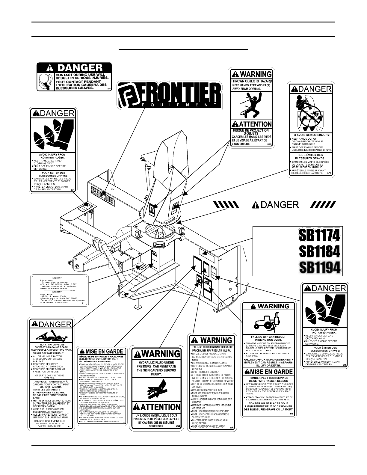
SAFETY DECA LS
Replace immediately if damaged.
5RD2500616
5RD2500606
5RD655834
RD2
7
5RD2500605
RD2500608
5RD2500620
5RD2500621
5RD2500776
5RD2500606
5RD2500614
5RD2500611
5RD2500604
OM 0369SB1174-A
5RD25006105RD2500400
10
ASSEMBLY
T
RACTOR PREPARATION
See Dealer for Tractor P r eparation information.
S
NOWBLOWER ASSEMBLY
The snowblower is assembled at the factory however snowblower kits must be assembled. Use the
present manual and lay out all parts for assembly. Separate bolts and nuts into various sizes. After
assembly, torque all the b olts according to the Torque Specification Table on page 54.
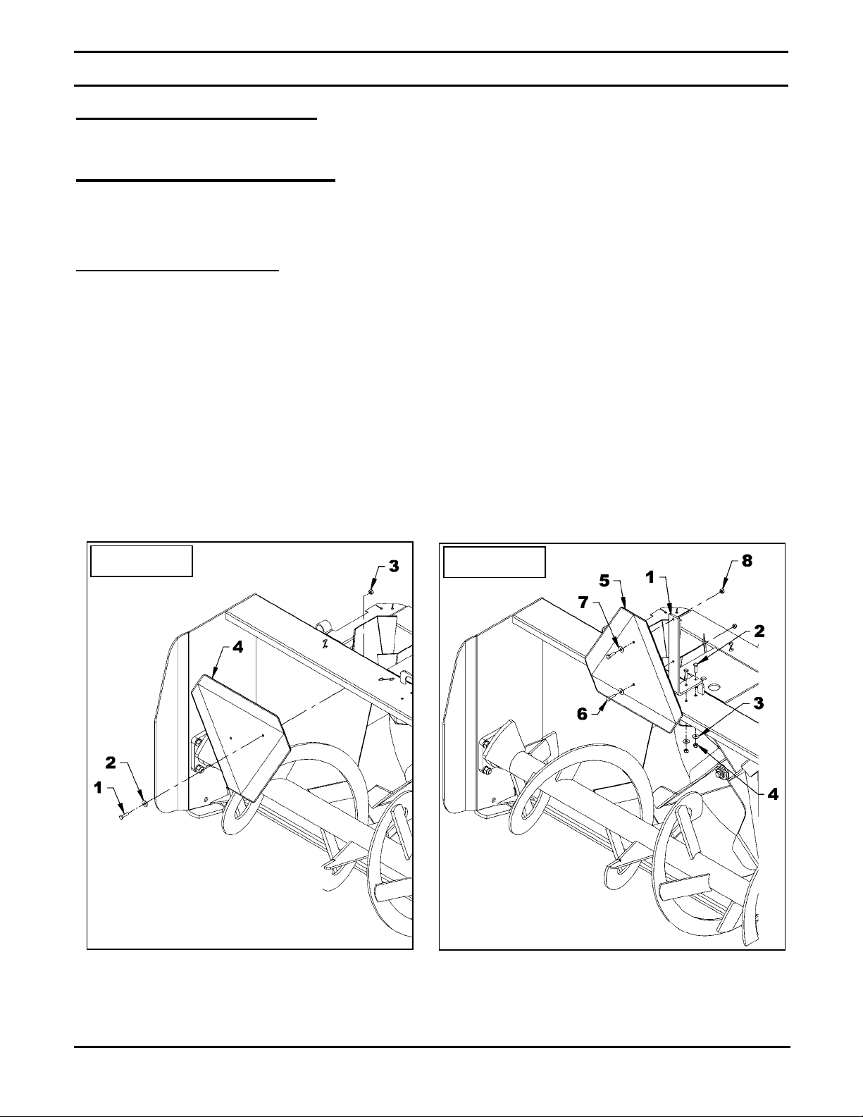
Installation of SMV Sign
(Figures 1-2)
1. Figure 1: Remove the 1/4" NC x 1" bolt, the
flat washer and the 1/4" nylon insert nut
(items 1-2-3) that fixes the sign (item 4) to
the frame. Save the hardware.
2. Figure 2: Install the sign support (item 1) on
the snowblower with two 1/4" NC x 1" bolts,
two 1/4" flat washers and two 1/4" NC nylon
insert nuts (items 2-3-4).
Figure 1
3. Figure 2: Using the hardware previously
removed, attach the SMV sign (item 5) with
two 1/4" NC x 1" bolts, two flat washers and
two 1/4" nylon insert nut (items 6-7-8).
4. Remove the black protective film from the
SMV sign.
Figure 2
OM 0369SB1174-A
11

ASSEMBLY
Installation of Chute and Manual Rotation Kit 5RDF0016
(Figures 3-4-5-6)
: The rotation handle can be installed
NOTE
on the right or left side of the three point
hitch.
1. Figure 4: Insert the 1 11/16" plastic
bushing (item 1) in the worm support
bracket (item 2) and insert the longest end
of the rotation w o rm (item 3).
8. Figure 5: Insert the handle support (item 9)
in the bracket (item 5) adjusting the height
of the support according to your needs and
secure in place with a 3/8" x 1/2" square
head setscrew (item 10).
9. Figure 5: Insert the grommet (item 11) in
the handle support (item 9).
2. Figure 4: Insert the 1 5/16" plastic bushing
(item 4) in the welded tube of the
snowblower (item 5).
3. Figure 4: Place the support (item 2) and
the support spacer (item 10) under the
snowblower's right upper plate (item 6).
4. Figure 3: Apply grease on the chute base
and around the snowblower chute ring and
install the chute (item 1) with the four
retaining plates (item 3), four spacers (item
2), eight 1/4" x 3/4" bolts and eight serrated
flange nuts (items 4-5). Tighten securely.
5. Figure 4: Insert the rotation tube (item 7) in
the worm assembly aligning the holes,
insert an Allen socket head capscrew 10-24
x 1" (item 8) making sure the screw sinks
into the rotation worm and secure with a
nylon insert nut (item 9).
6. Figure 5: Install the rotation bracket
(item 1) on the left or right arm of the three
point hitch with two 3/8" NC x 1 1/4" bolts,
lockwashers and nuts (items 2-3-4). Tighten
firmly.
10. Figure 6: Insert the handle (item 1) in the
handle support (item 4) and in the rotation
tube. Select desired length, align nearest
holes and secure with the 4 mm x 80mm
hairpin (item 2). Install the plastic handle
(item 3).
11. Figure 5: Once the snowblower is attached
to the tractor, adjust handle position and
height to ensure comfort and safe
operation. Tighten setscrew (item 10) on
the handle support as well as the 3/4" x
1 1/2" bolt, 3/4" lockwasher and 3/4" nut
(items 6-7-8).
12. Figure 6: To insure the manual rotation
functions properly, position the handle
support (item 4) the closest possible to the
top link mounting point of the three point
hitch while making sure it does not come
into contact with the operator's seat when
the snowblower is fully raised.
13. Tighten all bolts according to the Torque
Specification Table on page 54.
7. Figure 5: Attach the handle support
bracket (item 5) to the rotation bracket
(item 1) with a 3/4"NC x 1 1/4" bolt,
lockwasher and nut (items 6-7-8) making
sure to attach the brackets in the direction
illustrated.
OM 0369SB1174-A
CAUTION
To avoid personal injury, check the full lifting
range of the snowblower, to ensure that the
chute rotation handle is clear of the
operator’s area when the snowblower is in
raised position.
12
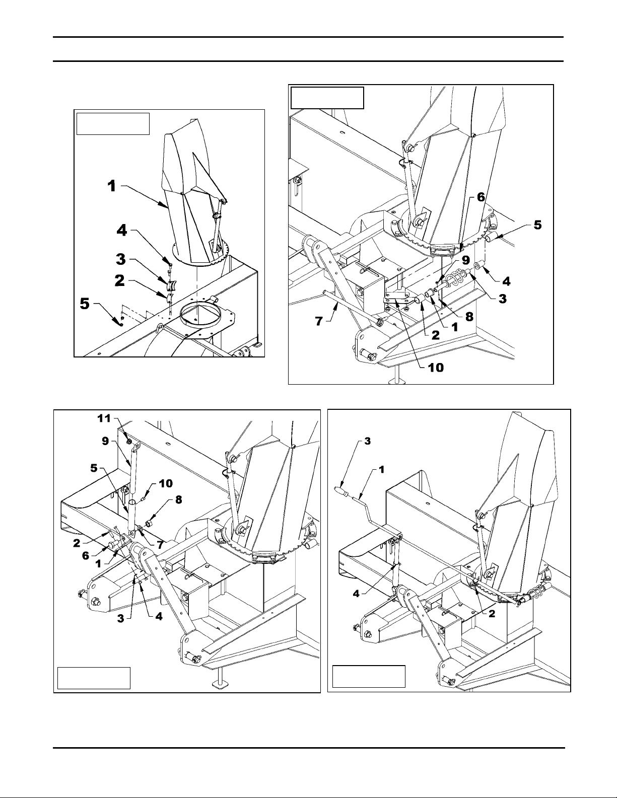
Figure 3
ASSEMBLY
Figure 4
Figure 5
OM 0369SB1174-A
Figure 6
13
ASSEMBLY
g
Installation of Chute and Hydraulic Rotation Kit 5RDF0018
(Figures 7-8-9)
1. Figure 7: Place the hole identified
"POSITION" over the indentation in the
housing.
2. Figure 7: Apply grease on the chute base
and around the snowblower chute ring and
install the chute with the four retaining
plates (item 1), eight 1/4" x 3/4" bolts and
eight serrated flange nuts (items 2-3). Do
not tighten immediately.
3. Figure 7: Attach the rotation bracket
(item 5) in the slot on the left side of the
housing with a 1/2"NC x 1 1/4’’ hex. bolt
and a 1/2" serrated flange nut (items 6-7).
4. Figure 7: Place the spacer ring (item 8) on
the 13/16" hole of the housing; insert the
pivot bushing (item 9) in the bell crank
(item 10) and slide the bell crank between
the flat bars of the rotation bracket (item 5).
5. Figure 7 – SB1174: Attach the other end
of the bracket (item 5) and the bell crank
(item 10) in the 13/16" hole of the housing
with the 3/4"NC x 4" hex. bolt, a 3/4"
lockwasher and a 3/4" hex. nut (items 1211-13) in the exact order shown. Tighten
securely.
6. Figures 7-8 – SB1184 & SB1194: Attach
the other end of the bracket and the bell
crank (fig. 7, items 5-10) in the 13/16" hole
of the housing with the 3/4"NC x 5" hex.
bolt, a 3/4" lockwasher and a 3/4" hex. nut
(fig. 8, items 1-2-3) in the exact order
shown. Tighten securely.
7. Figure 7: Grease generously both holes of
the push arm (item 17) and install one end
under the flat bar welded on the base of the
chute and secure with a 1/2’’ x 1" shoulder
screw, two 9/16" hole flat washer, a 3/8"
hole flat washer and a 3/8"NC stover nut
(items 14-18-15-16) in the exact order
shown. Tighten leaving some movement to
the mechanism.
8. Figure 7: Install the other end of the push
arm (item 17) under the bell crank (item 10)
and secure with a 1/2’’ x 1" shoulder screw,
a 9/16" hole flat washer, a 3/8" hole flat
washer and a 3/8"NC stover nut (items 1918-20-21) in the exact order shown.
Tighten leaving some movement to the
mechanism.
3. Figure 7: Attach the fixed section of the
cylinder (item 4) to the rotation br acket ( it em
5) and the sliding section to the bell crank
(item 10) placing a Ø 1 1/16" flat washer
(item 22) between the cylinder yoke and the
top of the bell crank then secure with the
cylinder pins and the circlips. Point the
hydraulic ports upward as illustrated.
NOTE: The 1 1/16" flat washer (item 22) is
required only if the cylinder pin rubs against
the snowblower housing
9. Figure 9: Connect the 3/8" ends of both
hoses (item 2) to the cylinder (item 1) and
install a quick coupler with rubber dust cap
(items 6-7) at the end of each hose.
10. Figure 9: Secure the hoses on the three
point hitch with the hose clamp, 3/8" NC x
1 1/2" lg bolt and 3/8" NC nylon insert nut
(items 4-3-5) and attach hoses together
with the nylon tie wraps (item 8) where
needed.
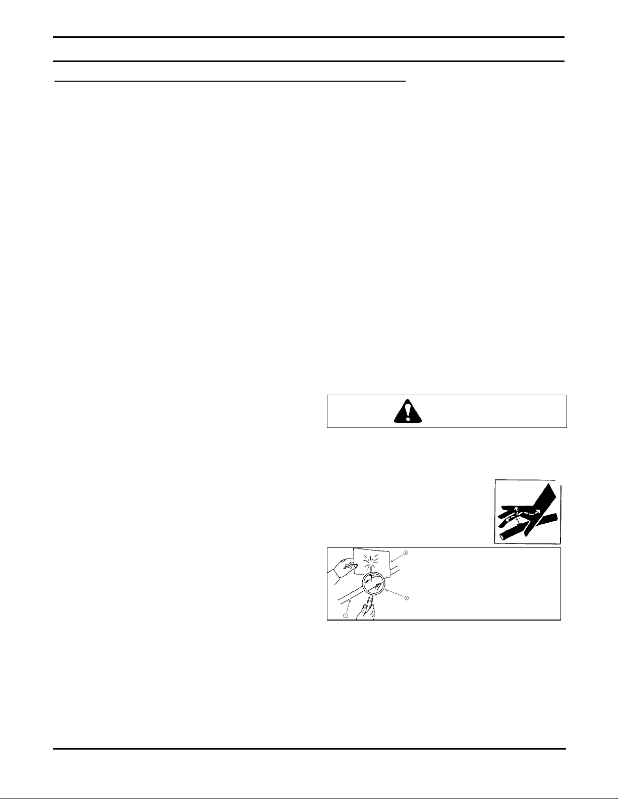
CAUTION
To avoid serious personal injury.
hydraulic/ diesel fluid under pressure can
penetrate the skin causing ser ious injury
• Do not use your hands to
check for leaks. Use a
piece of cardboard or
paper to search for leaks.
• Stop engine and relieve pressure before
connecting or disconnecting lines.
• Tighten all connections before starting
engine or pressurizing lines.
If any fluid is injected into the skin, obtain
medical attention immediately or gangrene
may result.
1. Hydraulic ho se
2. Cardboard
nifying glass
3. Ma
Escaping
.
OM 0369SB1174-A
14
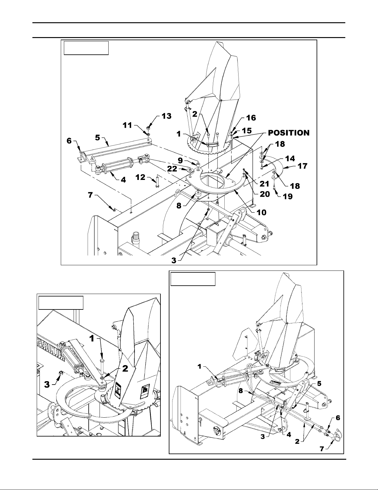
Figure 7
ASSEMBLY
Figure 8
Figure 9
OM 0369SB1174-A
15
ASSEMBLY
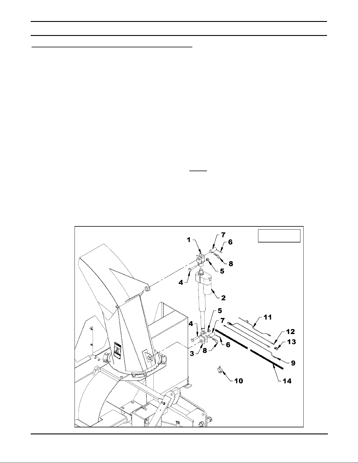
Installation of Electric Deflec tor Kit 5 RDF0021
(Figures 10-11-12 & Electrical Diagram)
1. Figure 10: Install the longest clevis
(item 1) on the actuator base (item 2), the
shortest one (item 3) on the other end and
attach with two 1/2" NC x 2 1/2" bolts and
1/2" NC nylon insert locknuts (items 4-5).
2. Figure 10: Install a 3/16" x 1 3/4" spring
pin (item 6) on each 1" pin (item 7).
3. Figure 10: Attach the actuator using the
two 1" pins (item 7) and secure with 4mm x
80mm hairpins (item 8).
4. Figure 10 & diagram: Connect the wires
to the switch (item 10) as follows:
• 72" black ground wire (item 9) to terminal
"C" (see diagram).
• 72" red fuse wire (item 11) to terminal "B
(see diagram).
• 360" red and black actuator wires
(item 12) to terminal "A" and "D" (see
diagram).
5. Figure 11: Insert the switch (item 4) in the
switchbox (item 2), secure with the two nuts
(items 1-3) supplied with the switch and
screw the rubber cap (item 5) on the switch
in the order shown.
6. Figure 12: Place the switchbox (item 1) on
the lever in a position that will be
comfortable when the hand is on the knob
and attach with the box clamp (item 5), two
1/4"NC x 3/4" hex. bolts and two 1/4"
lockwashers (items 3-4) making sure the
clamp is in the right direction so the lower
openings on the switchbox are not blocked.
: Tighten the bolts just enough to securely
NOTE
fix the clamp and the switchbox on the lever. DO
NOT TIGHTEN TOO MUCH so the clamp
doesn't deform.
Figure 10
OM 0369SB1174-A
16

ASSEMBLY
7. Figure 10: Connect the ground wire's
round terminal (item 9) to any grounding
screw on the tractor.
8. Figure 10: Connect the fuse wire (item 11)
to the tractor ignition switch wire using the
tap connector (item 13).
9. Figure 10: Connect the actuator wires'
female connector (item 12) to the electric
actuator (item 2).
10. Figure 10: Place the loom (item 16) around
all the wires to protect them. Secure the
loom using tie wraps.
Figure 11
Figure 12
ELECTRICAL DIAGRAM
OM 0369SB1174-A
17

ASSEMBLY
Installation of Hydraulic Deflector Kit 5RDF009
(Figures 13-14)
1. Figure 13: Remove a circlip (items 1-4)
from each cylinder pin (items 2-3) and
remove the pins. Placing the hydraulic ports
in the position shown on figure 14, attach
the fixed end of the cylinder (item 6) to the
chute base (item 5) and the rod end to the
upper chute bracket with the pins and
circlips (items 1-2-3-4).
2. Figure 14 Connect the 3/8" ends of both
hoses (item 2) to the cylinder (item 1) and
install a quick coupler with rubber dust cap
(items 6-7) at the end of each hose.
3. Figure 14: Secure the hoses on the three
point hitch with the hose clamp, 3/8" NC x
1 1/2" lg bolt and 3/8" NC nylon insert nut
(items 4-3-5) and attach hoses together
with the nylon tie wraps (item 8) where
needed.
: Make sure to leave enough slack to the
Note
hoses to all o w compl e te r ota ti on mov e me nt s.
Figure 13
Figure 14
OM 0369SB1174-A
18

ASSEMBLY
Installation of Snowblower with Three Point Hitch
(Figures 15-16-17)
SB1174
(Figure 15)
1. Install the two cat.1 pins ( item 1) on the right
and left snowblower hitches in the lower holes
as shown on figure.
2. Category 1: Attach tractor lower links (item 2)
to the snowblower hitch pins (item 1) and
secure with the li n ch pins (item 3).
3. Category 2: Insert the 1 1/8" OD x 1 3/4" lg
bushings (item 9) on each pin (item 1). Attach
tractor lower links (item 2) to the snowblower
hitch pins (item 1) and secure with the
linchpins (item 3).
4. Category 1: Attach the tractor upper link
(item 4) between the upper attaching plates
(item 6) using the tractor pin and linchpin
(item 5 – not included).
5. Category 2: Insert a 1 1/4" OD x 1 7/8" lg
bushing (item 10) on the tractor pin (item 5-not
included). Attach the tractor upper link (item 4)
between the upper attaching plates (item 6)
using the tractor pin and linchpin (item 5 – not
included).
6. Adjust the snowblower using the tractor upper
link so that the snowblower operates parallel to
the ground.
7. Set the tractor anti-sway turnbuckles so the
snowblower does not sway. Be sure there is
no contact with the tires.
8. Install the eyebolt (item 7) in the upper hole of
the left or right side of the three point hitch by
screwing the eyebolt nut to the top and locking
eyebolt in place with a 3/8" serrated flange nut
(item 8).
CAUTION
Before connecting snowblower driveline to
tractor drive shaft, make sure driveline is not
too long in raised, lowered and middle
position. If the driveline is too long it must be
shortened, to avoid damaged to tractor. See
pages 24 to 26 for instructions.
Figure 15
OM 0369SB1174-A
19

SB1184
(Figures 16-17)
ASSEMBLY
CATEGORY 1
(Figure 16)
1. Install the two cat.1 pins (item 1) on the right
and left snowblower hitches in the lower
holes of the inside plates as shown on figure.
2. Attach tractor lower links (item 2) to the
snowblower hitch pins (item 1) and secure
with the linchpins (item 3).
3. Attach the tractor upper link (item 4) between
the upper attaching plates (item 6) using the
pin and linchpin (item 5 – not included).
4. Adjust the snowblower using the tractor
upper link so that the snowblower operates
parallel to the ground.
5. Set the tractor anti-sway turnbuckles so the
snowblower does not sway making sure
there is no contact with the tires.
6. Install the eyebolt (item 7) in the upper hole
of the left or right side of the three point hitch
by screwing the eyebolt nut to the top and
locking eyebolt in place with a 3/8" serrated
flange nut (item 8).
CAUTION
Before connecting snowblower driveline to
tractor drive shaft, make sure driveline is not
too long in raised, lowered and middle
position. If the driveline is too long it must be
shortened, to avoid damaged to tractor. See
pages 24 to 26 for instructions.
CATEGORY 1
Figure 16
OM 0369SB1174-A
20

SB1184 & SB1194
CATEGORY 2
(Figure 17
ASSEMBLY
1. Install the two cat. 2 pins (item 1) on the
right and left snowblower hitches in the
lower holes of the outside plates as shown
on figure.
2. Attach tractor lower links (item 2) to the
snowblower hitch pins (item 1) and secure
with the linchpins (item 3).
3. Attach the tractor upper link (item 4)
between the upper attaching plates (item 6)
using the tractor pin and linchpin (item 5 –
not included).
4. Adjust the snowblower using the tractor
upper link so that the snowblower operates
parallel to the ground.
5. Set the tractor anti-sway turnbuckles so the
snowblower does not sway. Be sure there
is no contact with the tires.
6.
CATEGORY 2
Install the eyebolt (item 7) in the upper hole
of the left or right side of the three point
hitch by screwing the eyebolt nut to the top
and locking eyebolt in place with a 3/8"
serrated flange nut (item 8).
CAUTION
Before connecting snowblower driveline to
tractor drive shaft, make sure driveline is not
too long in raised, lowered and middle
position. If the driveline is too long it must be
shortened, to avoid damaged to tractor. See
pages 24 to 26 for instructions.
Figure 17
OM 0369SB1174-A
21

ASSEMBLY
Installation of Snowblower with Quick Hitch
(Figures 18-19-20)
SB1174
(Figure 18)
CATEGORY 1 only
1. Install the two cat.1 pins (item 2) on the right
and left snowblower hitches in the upper
holes leaving 3 1/4" between the jam nut and
the end of the pin as shown on figure.
2. Insert the two 2 1/8" lg bushings (item 3) on
each pin and lock in place with the two 7/16"
linchpins (item 4).
3. Insert the 1 7/8" lg bushing (item 5) between
the upper attaching plates and lock in place
with the tractor hitch pin and a 7/16" linchpin
(items 6-7).
4. Install the eyebolt (item 8) in the upper hole of
the left or right side of the three point hitch by
screwing the eyebolt nut to the top and
locking eyebolt in place with a 3/8" serrated
flange nut (item 9).
Figure 18
CAUTION
Before connecting snowblower driveline to
tractor drive shaft, make sure driveline is
not too long in raised, lowered and middle
position. If the driveline is too long it must
be shortened, to avoid damaged to tractor.
See pages 24 to 26 for instructions.
OM 0369SB1174-A
22

ASSEMBLY
SB1184
(Figures 19-20)
CATEGORY 1
(Figure 19)
1. Place the two 1 1/2" x 2 1/8" lg bushings
(item 3) between upper holes of the interior
and middle plates, insert the 1 1/8" x 6 1/4"
lg cat.2 pins (item 2) from the inside and
lock in place with 7/16" linchpins (items 4).
2. Insert the 1 7/8" lg bushing (item 5) between
the upper attaching plates and lock in place
with the 3/4" x 5 7/16" pin and a 7/16"
linchpin (items 6-7).
3. Install the eyebolt (it em 8) in the upper hole
of the left or right side of the three point
hitch by screwing the eyebolt nut to the top
and locking eyebolt in place with a 3/8"
serrated flange nut (item 9).
CAUTION
SB1194
(Figure 20 only)
CATEGORY 2
(Figure 20)
1. Place the two 1 1/2" x 3 3/8" lg bushings
(item 3) between upper holes of the exterior
and middle plates, insert the 1 1/8" x 6 1/4"
lg cat.2 pins (item 2) from the outside and
lock in place with 7/16" linchpins (items 4).
2. Insert the 1 7/8" lg bushing ( it em 5) between
the upper attaching plates and lock in place
with the 3/4" x 5 7/16" pin and a 7/16"
linchpin (items 6-7).
3. Install the eyebolt (item 8) in t he upper hole
of the left or right side of the three point
hitch by screwing the eyebolt nut to the top
and locking eyebolt in place with a 3/8"
serrated flange nut (item 9).
CAUTION
Before connecting snowblower driveline to
tractor drive shaft, make sure driveline is not
too long in raised, lowered and middle
position. If the driveline is too long it must be
shortened, to avoid damaged to tractor. See
pages 24 to 26 for instructions.
CATEGORY 1
Figure 19
Before connecting snowblower driveline to
tractor drive shaft, make sure driveline is not
too long in raised, lowered and middle
position. If the driveline is too long it must be
shortened, to avoid damaged to tractor. See
pages 24 to 26 for instructions.
CATEGORY 2
Figure 20
OM 0369SB1174-A
23

ASSEMBLY
IMPORTANT
A proper initial installation will give you years of
satisfactory service on your equipment. Please
read carefully following instructions that have
been specially included to help you and ensure
you are satisfied with your purchase.
Unfortunately, snowblowers will be faced
with forgotten or hidden objects under the
snow, such as : chain, tires, stones, pieces
of wood, etc. In spite of all our efforts,
machines are not built to resist all those
conditions.
How to Determine Driveline Angles
IMPORTANT:
joint angles, it is recommended to adjust the
three point hitch at the furthest point from the
tractor recommended by the manufacturer
Angles of Driveline Joints Too Large
:
WARNING
To obtain the proper universal
Avoid
Danger: Tractors Too Big
It is dangerous to use a tractor that is too big and
powerful. The tractor will always be able to
overload the blower, even if the machine is
already at maximum capacity. Furthermore,
tractors being very high, the driveline angles will
be excessive which means the universal joints
will be very vulnerable and the life of the driveline
will be dramatically reduced.
The universal joint angle is directly related with
the life of driveline. In order to reduce the angle, it
is necessary to increase the distance between
the snowblower and the tractor.
Reasonable Angles of Drive line Joints
Acceptable
OM 0369SB1174-A
24

ASSEMBLY
Unequal Angles at Driveline Joints
Avoid
Angles at Each End of Driv eline
A popular habit is to change the snowblower
angle in order to obtain a better scraping effect.
This practice can become harmful to the
driveline since the angle at each end is
unequal. This results in a fan speed variation as
well as a drastic increase of load on cross and
bearings. To be avoided: It is recommended to
always keep tractor driveline and snowblower
input shaft parallel.
Figure 21
Equal Angles at Driveline Joints
Recommended
Determining Drivel ine Length
IMPORTANT
make sure the driveline is not too long. At
working position, the two half drivelines must
intersect each other sufficiently to insure
maximum efficiency but there must not be any
interference.
1. To determine the "L" length for your tractor
model first find the "X" factor by measuring
the horizontal distance between the end of
the tractor's drive shaft and the end of the
snowblower's driven shaft when the
snowblower is in transport position as shown
on Figure 21.
2. Choose in the table below the "Y" factor
according to the tractor category and deduct
that number from "X" to determine "L" which
is the center-to-center length between the
universal joints.
: Before using the equipment,
L = X – Y
3 PTS HITCH
CATEGORY
Y
Cat. 1 4 1/2"
Cat. 2 5 1/2"
OM 0369SB1174-A
25

ASSEMBLY
A
NOTE: Before cutt ing, make sure the two shafts
intersect by at least 7 3/4" when in working
position that is when the snowblower rests on the
ground.
3. Hold the two half-shaft side by side and
locate the "L" length between the two centerto-center half-shaft universal joints. Mark off
the zone to be cut on both halves opposite
each half-shaft guard as shown on Figure
22.
4. Cut off inner and outer guard tubes a s well as
the inner and outer telescopic sections.
5. Cut the guard a second time leaving the
same distance between the end of the guard
and the end of the shaft as existed before.
To obtain the proper distance "A" shown on
Figure 23, cut the guard according to the
followi n g tab le :
DIS TANCE A
Male PTO Female PTO
1 3/4" 1 1/4"
6. File down tubes and remove chips.
7. Apply grease to inside of outer telescopic
section.
IMPORTANT
only!
: W ork with f ull y guar ded shaft s
Figure 23
Figure 22
OM 0369SB1174-A
26

ASSEMBLY
Driveline Installation
(Figure 24)
1. Separate the snowblower from the three
point or quick hitch.
2. Remove paint from snowblower gearbox
shaft (item 1) and grease driveline sliding
surfaces and yoke (item 2).
3. Remove the bolts (it ems 3) fr om the driveline
yoke (item 2) and slide yoke over drive shaft
using the sliding action of the driveline. Make
sure the driveline is well secur ed to the shaft
by reinstalling the bolts and nuts (item 3-4) in
the order shown. Tighten the bolts according
to the Torque Specification Table on
page 54.
4. Attach safety chain (item 5) around the upper
link (item 6) to prevent the guard from
spinning.
Figure 24
OM 0369SB1174-A
27

ASSEMBLY
Removing S nowbl ower from Trac tor
(Figures 25-26-27)
Three Point Hit ch
1. Set parking brake and turn engine off.
2. Figure 25: Remove the wire round lock pin
(item 2), lower the parking stand (item 1)
completely to the ground to release all
pressure from the three-point and reinsert the
wire round lock pin in the lower hole (item 3).
3. Figure 26: Detach upper link (item 4) by
removing linchpin and pin (items 6-5).
4. Figure 26: Disconnect driveline from tractor
and attach the driveline safety chain (item 7) to
the three point hitch eyebolt (item 8).
5. Figure 26: Carefully detach lower links
(items 2) from hitch pins (item 1) by removing
linchpins (items 3), loosen anti-sway
turnbuckles and slowly back tractor away from
the snowblower.
IMPORTANT
snowblower, retorque all bolts after the first 10
hours of operation.
: To avoid damages to the
Figure 25
Figure 26
OM 0369SB1174-A
28

ASSEMBLY
Quick Hitch
1. Set parking brake and turn engine off.
2. Figure 25: Remove the wire round lock pin
(item 2), lower the parking stand (item 1) and
reinsert the wire round lock pin in the lower
hole (item 3).
3. Figure 27: Disconnect driveline (item 1) from
tractor and attach the driveline safety chain
(item 2) to the three point hitch eyebolt
(item 3).
4. Figure 27: Slowly back the tractor away to
release quick hitch (item 4) from the
snowblower.
Figure 27
OM 0369SB1174-A
29

G
ENERAL PREPARATION
OPERATION
A
DJUSTMENTS
1. Read the operator’s manual carefully before
using the tractor and snowblower. Be
thoroughly familiar with the controls and
proper use of the equipment. Know how to
stop the unit and disengage the controls
quickly.
2. Make sure the snowblower is clear of snow
before engaging the driveline.
3. Make sure the auger and fan operate freely.
4. Check the oil level in the worm Gearbox and if
necessary, add 80W90 SAE gear oil, AGMA
5EP oil or equivalent.
5. Check the two shear bolts, one on the driving
shaft, and the one on the PTO, for proper
tightness.
6. Adjust so that the snowblower skid shoes run
level.
7. Wear adequate winter outer garments while
operating equipment.
O
PERATING CONTROLS
Work and Travel Speed
Working ground speed will depend on the depth
and density of the snow to be cleared. Normally,
ground speed will range from 4 to 7 MPH for light,
dry snowfalls 3 to 6 inches, and 1 to 3 MPH for
heavy, wet or drifted snow. To transport,
disengage the drive shaft and raise the
snowblower to full transport height.
Raising and Lowering the Snowblower
Move the three point lever on right hand side of
seat down or forward to lower, and up or rearward
to raise.
Reduction Chain Tension Adjustment
(Figure 28)
The prem ature wear of the chain ma y be caused by
tension being too tight. It is therefore important not to
tighten chai n to i ts max i mu m.
• To adjust the tension on the drive chain, loosen the
bolt (item 1), securing the idler sprocket to the
snowblower housing.
• To tighten the chain, lower the bolt. Leave
approximately 1/8" deflection in one span of the
chain. Retighten securely the bolt holding the idler
sprocket.
Skid Shoe Adjustment
(Figure 28)
Adjust the skid shoes so that the snowblower runs
level and according to the surface conditions so that
stones are not thrown with the snow.
Adjust both skid shoes to the same height to keep the
cutting edge level and adjust upwards for smooth
surfaces.
Loosen skid shoe bolts (item 2) and adjust according
to instructions below, a nd securely tighten bolts:
Clearance between cutting edge and surf ace:
• Paved surface: Insert bolts in lower hole.
• Uneven or gravel surface: Insert bolts according to
distance needed: 1/2" - middle hole
1" - uppe r hole
1
2
WARNING
To avoid personal injury, be sure the tractor
engine is off, the dr ive shaft diseng aged, an d
all movement has stopped before making any
adjustments.
OM 0369SB1174-A
Figure 28
Manual Deflector A dj u stment
Set the angle of deflection according to the distance
the snow must be thrown. To set the deflector angle,
remove the adjusting pipe hairpin and adjust the
adjusting rod to the desired deflector angle. Secure
with the adjusting pipe hai rpin.
30

OPERATION
S
NOW REMOVAL METHODS
When remo ving snow, do not use the snowb lower as a dozer blade to push snow. Let the snowblower
work its way through deep drifts. If the speed of your tractor is too fast, the snowblower may become
overloaded and clog. For best results, raise the snowblower and remove a top layer of snow. A second
pass with the snowblower will remove the remaining snow.
IMPORTANT
Do not use hands or feet to unclog chute. Do not attempt to clear clogged chute of snow while tractor
engine is running. If the chute clogs, disengage the drive shaft, shut off the tractor engine, remove the
ignition key, wait for all movement to stop, and then clear the snow from the chute.
A definite pattern of operation is required to thoroughly clean the snow area. These patterns will avoid
throwing snow in unwanted places as well a s elimi natin g a second removal of snow
: Use full RPM power when removing wet, sticky snow. Low RPM power will tend to clog the
chute.
WARNING
Where it is possible to throw the snow to the left
and right (above), as on a long driveway, it is
advantageous to start in the middle. Plow from
one end to the other, throwing snow to both sides
without changing the direction of the discharge
guide
OM 0369SB1174-A
If the snow can only be thrown to one side of the
driveway or sidewalk (above), start on the opposite
side. At the end of the first pass, rotate the
discharge guide 180 degrees for the return pass.
At the end of each succeeding pass, rotate the
discharge guide 180 degrees to maintain direction
of throw in the sa me area.
31

MAINTENA NCE
M
AINTENANCE
Shearbolts
Check the shearbolts indicated on the figure
below at frequent intervals for proper tightness to
be sure the blower is in safe working condition. If
the shearbolts need replacement, use the
following parts only:
Drive shaft
Shearbolt hex. 5/16" NC x 1 3/4" gr.5, incl. nut.
Part # 5RD665547.
Driveline
SB1174
Shearbolt M8 x 1.25 x 50 mm gr. 6.6 and nut.
Part # 5RD4700060 .
SB1184 & SB1194
Shearbolt M10 x 1.5 x 55 mm gr. 8.8 and nut.
Part # 5RD657199.
:
:
WARNING
Provide adequate blocking before working
under the snowblower when in the raised
position.
Driveline
IMPORTANT: When the snowblower is not
used for more than two weeks, perform
driveline maintenance and always store it in a
dry place, away from bad weather conditions.
OM 0369SB1174-A
32

MAINTENA NCE
L
UBRICATION
Use oil or a grease gun and lubricate as follow s :
DESCRIPTION INTERVAL LUBRICATION REQUIRED
Driveline
8 hours
16 hours Oil the push pins
Grease each universal joint. Separate the sliding
parts and cover each one of them with grease
Chain
Drive Sh aft 24 hours of operation Grease fitting on shear plate
Gearbox
Bearing 24 hours of operation Grease each auger bearing
and after each operation
4 hours
Every month
Once a year Replace oil
Lubricate with chain lube
Check oil level. If needed, add AGMA 5EP extreme
pressure oil, SAE 80W90 gear oil or equivalent.
OM 0369SB1174-A
33

MAINTENA NCE
D
RIVELINE TROUBLESHOOTING
Q
UICK-DISCONNECT YOKE
AVOIDABLE DAMAGES POSSIBLE CAUSES CORRECTIVE ACTIONS
! Quick-disconnect pin tight or
completely seized.
! Quick-disconnect pin
damaged (broke n or bent )
! Quick-disconnect pin
damaged in the locking
portion.
! Quick-disconnect pin dirty
(insufficient maintenance).
! Quick-disconnect pin
defective (for ced
engagement, inc orre ct
handling)
! Ex cessiv e sh aft le ngth .
! Ax ial load s too hi gh.
Note: Quick-disconnect pins must be cleaned and greased every 16 hours.
Y
OKE
AVOIDABLE DAMAGES POSSIBLE CAUSES CORRECTIVE ACTIONS
! Yoke ears deformation
! Ex cessiv e sh aft le ngth .
! Ax ial load s too hi gh.
! Excessive working angle
and torque.
! Clean , oi l and fo llow servi ce
instructio ns.
! Replace quick-disconnect pin.
! Shorten shaft length (cut both
telescopic tubes as well as
shield and remove burrs).
! Replace quick-disconnect pin.
! Clean and grease telescopic
tubes, and replace both tubes,
if necessary.
! Replace quick-disconnect pin.
! Shorten shaft length (cut both
telescopic tubes as well as
shields and remove burrs).
! Replace defective yokes.
! Clean and grease telescopic
tubes, and repl ace both tube s,
if necessary.
! Replace defective yokes.
! Verify compatibility between
shaft and working conditions
(torque vs. angle).
! Disengage tractor driveline
during cornering or when lifting
or lowering the imp leme nt.
! Change to a larger driveline
size.
! Replace defective yokes.
OM 0369SB1174-A
! Yoke ears distorted.
Yoke ears worn or poun ded.
! Overload caused by high
starting and peak torques.
! Excessive working angle. ! Avoid excessive working
! Engage driveline more
carefully.
! Use appropriate safety
devices.
! Replace defective yokes.
angle.
! Disengage tractor driveline
during cornerin g.
! Replace defective yokes.
34

C
ROSS KIT
MAINTENA NCE
AVOIDABLE DAMAGES POSSIBLE CAUSES CORRECTIVE ACTIONS
! Cross arms broken.
! Extreme torque peak or
shock load.
! Ax ial load s too hi gh.
! Use appropriate safety device.
! Change to a larger driveline
size.
! Shor ten dr ive line sh aft.
! Replace defective cross
bearings.
! Bearing caps turning in their
cross journa l.
! Overheated bearing caps.
! Excessive continuous
torque and/or ex ces sive
working angle.
! Inadequate greasing.
! Verify compatibility between
shaft and worki ng co ndit io ns.
! Carefully follow greasing
instructio ns.
! Replace defective cross
bearings.
! Accelerated wear of cross kit. ! Excessive continuous
torque and/or ex ces sive
working angle.
! Inadequate greasing.
! Verify compatibility between
shaft and worki ng co ndit io ns.
! Carefully follow greasing
instructio ns.
! Replace defective cross
bearings.
Note: Cross bearings must be greased every 8 working hours.
AVOIDABLE DA MAGES POSSIBLE CAUSES CORRECTIVE ACTIONS
T
ELESCOPIC TUBES
! Telescopic tubes failure or
twisting.
! Extreme torque peak or
shock load.
! Short tube engagement.
! Use appropriate safety device.
! Change to a larger driveline
size.
! Replace the driveline drive
shaft with one hav in g
adequate length.
! Replace defective tubes.
Accelerated wear of telescopic
tubes.
! Extreme load when sliding.
! Short tube engagement.
! Inadequate greasing.
! Dirt
Note: Telescopic tubes must be cleaned and greased every 8 working hours.
OM 0369SB1174-A
35
! Change to a driveline with
rilsan coated inner tube.
! Replace the driveline with one
having adequate length.
! Carefully follow greasing
instructio ns.
! Replace defective tubes.

MAINTENA NCE
SHIELD
AVOIDABLE DAMAGES POSSIBLE CAUSES CORRECTIVE ACTIONS
! Excessive wear of shield
bearings.
! Chain moving or failure.
! Shield cone damaged.
! Shield tubes damaged
(deformed and split at one
side).
! Insufficient lubrication.
! Incorrect chain mounting.
! Shield interfering with
implement.
! Shield interfering with
implement.
! Incorrect chain mounting.
! Shield cone in contact with
components on the tractor
and/or implement .
! Excessive angularity.
! Shields in contact with
components on the tractor
and/or implement .
! Shield tubes overlap too
short or no overlap at all
with extended driv el ine.
! Follow lubrication instructions.
! Mount chain to allow
maximum angula rity .
! Avoid contact of the shields
with fixed parts of the mac hin e
or tractor.
! Replace shield bearings.
! Avoid contact of the shields
with fixed parts of the mac hin e
or tractor.
! Mount chain to allow
maximum angula rity .
! Replace defective parts.
! Eliminate interference
between Shield cones and any
part on the tractor an d/or
implement.
! Avoi d ex cess ive ang le duri ng
cornering or when li ftin g or
lowering th e im pl ement.
! Replace damaged Shield
cones.
! Eliminate interference
between Shield co ne s and
any part on the tractor an d/or
implement.
! Replace damaged tubes.
! Adjust Shield tubes length
with longer tubes .
Note: Shield bearings must be greased every 8 working hours.
OM 0369SB1174-A
36

PARTS
I
NTRODUCTION
All parts are illustrated in "exploded views" which show the individual parts in their normal relationship to
each other. Reference numbers are used in the illustrations. These numbers correspond to those in the
"Reference Number" (REF) column, and are followed by the desc rip tion and quantity required .
Right Hand and Left Hand a re determined by those seen by the conductor standing behind the equipment.
The manufacturer reserves the rights to change, modify, or eliminate from time to time, for technical or
other reasons, certain or all data, specifications, or the product or products themselves, without any liability
or obligation.
The parts listed here are available through your loc al de aler.
M
ANUAL HOLDER – ALL MODELS
R
EF
. D
ESCRIPTION
1 Manual holder 1 5RD4200030
2 Bolt hex. 5/16" NC x 3/4" lg gr. 5 , PTD 2 5RD0100018
3 Nut nylon inser t 5 /16 " NC, PTD 2 5RD1000005
Q
TY
P
ART
#
OM 0369SB1174-A
37

S
NOWBLOWER
PARTS
– SB1174
OM 0369SB1174-A
38

PARTS
R
S
NOWBLOWER
EF
. D
ESCRIPTION
1 Housing 1 --2 Chute assembly (including adjustment tube and ro d) 1 5RD668101
3 Adjustment rod 1 5RD654074
4 Adjustment tube 1 5RD654076
5 Serrated flange nut 1/2" NC PTD 12 5RD0900046
6 Retaining plate 4 5RD654197
7 Bolt hex. 1/2" NC x 1 1/4" gr.5 PTD 8 5RD0100069
8 Cotter pin Ø1/4" x 2 " PTD 4 5RD1500022
9 Round wire lock pin 1/4" x 2" PTD 2 5RD1900006
10 Bolt hex. 1/4" NC x 1" gr.5 PTD 4 5RD0100004
11 Flat washer 1/4" (5/16" dia. hole) PTD 4 5RD1400002
12 Nylon insert locknut 1/4" NC PTD 4 5RD1000003
13 S.M.V. sign support 1 5RD668109
14 S.M.V. reflective sign 1 5RD4200029
15 Serrated flange nut 3/8" NC PTD 8 5RD0900035
16 Bushing 1 1/4" OD x 1 7/8" l g 1 5RD668058
17 Bolt hex. 3/8" NC x 1 1/2" gr.5 P TD 5 5RD0100040
18 Lockwasher 3/8" PTD 1 5RD1200004
19 Flat washer 3/8" 1 5RD1400003
20 Fan washer 1 5RD661554
21 Fan 1 5RD668966
22 Key 3/8" x 3/8" x 2 3/4" lg
23 Driveline Series 40 1 5RD4700159
Driveline Series 50 24 Driveline shield bracket 1 5RD668097
25 Hairpin 3mm x 65mm lg PTD 1 5RD1800004
26 Driveline shield 1 5RD668057
27 Bolt hex. 3/8" NC x 5" gr.5 PTD 4 5RD0100051
28 Flange, 3 holes with grease fitting and groove 1 5RD4300015
29 Nut hex. 5/16" NC PTD 1 5RD0900002
30 Shear plate 1 5RD666257
31 Oilite bushing 1 5RD4300056
32 Shearbolt 5/16"NC x 1 3/4" gr.5, incl. nut 1 5RD665547
33 Lockwasher 5/16" PTD 1 5RD1200003
34 Grease fitting 1/4" NF 1 5RD654106
35 Parking stand 1 5RD668053
36 Bearing 1 1/8" with setscrew and grease system 1 5RD4300040
37 Bolt hex. 1/4" NC x 1 1/4" gr. 5 PTD 1 5RD0100005
38 Nylon insert hex. nut 1/4" NC PTD 1 5RD1000003
39 Bushing 1.5 OD x 2 1/8" lg PTD 2 5RD668059
40 Bushing 1 1/8" OD x 1 3/4" lg PTD 2 5RD4600045
41 Linchpin 7/16" PTD 2 5RD1900003
42 Hitch pin 7/8" x 5 1/2" lg Cat. 1 2 5RD654196
43 Chain #60 x 78 links 1 5RD654009
44 Connecting link #60
– SB1174
Q
serial #: XFSB11X080 102 to XFSB11 X0804 06
1 5RD662194
TY
P
1
1
5RD654174
5RD654839
ART
#
OM 0369SB1174-A
39

PARTS
S
NOWBLOWER
R
EF
. D
ESCRIPTION
45 Spacer ring .656"ID x 1.760 x 1" ext. 1 5RD668093
46 Idler sprocket 60A12 1 5RD3300022
47 Spacer ring .656"ID x .807 x 1" ext. 1 5RD667777
48 Flange, 3 holes with grease gr oov e 1 5RD4300014
49 Bolt carriage 1/2" NC x 1" lg gr.5 PTD 4 5RD0300022
50 Left adjustable skid shoe 1 5RD666254
51 Right adjustable skid shoe 1 5RD666255
52 Flange bearing 1 1/4" hole, 4 holes 2 5RD4300001
53 Lockwasher 1/2" PTD 8 5RD1200006
54 Nut hex. 1/2" NC PTD 8 5RD0900006
55 Bolt carriage 3/8" NC x 3/4" lg 3 5RD0300007
56 Sprocket 60A32 1 5RD654167
57 Nylon insert nut 3/8" NC gr.5 PTD 4 5RD1000006
58 Bolt hex. 1/2" NC x 1 1/2" l g gr.5 PTD 8 5RD0100070
59 Bolt hex. 5/8" NC x 4 1/2" l g gr.5 PTD 1 5RD0100104
60 Flat washer 5/8" (11/16" dia. hole) 2 5RD1400008
61 Lockwasher 5/8" PTD 1 5RD1200007
62 Nut hex. 5/8" NC gr.5 PTD 1 5RD0900007
63 Spacer ring 1 3/32" lg 1 5RD667015
64 Spacer 4 5RD668549
65 Driving shaft 1 5RD666272
66 Eyebolt 3/8" NC x 4" lg inc. nut 1 5RD0400027
67 Gearbox 1 5RD663485
68 Auger 1 5RD666271
– SB1174
Q
TY
P
ART
#
OM 0369SB1174-A
40

S
NOWBLOWER
PARTS
– SB1184 & SB1194
OM 0369SB1174-A
41

PARTS
R
S
NOWBLOWER
EF
. D
ESCRIPTION
1 Housing 1 --2 Chute assembly (including adjustment tube and ro d) 1 5RD668101
3 Adjustment rod 1 5RD654074
4 Adjustment tube 1 5RD654076
5 Serrated flange nut 1/2" NC PTD 8 5RD0900046
6 Retaining plate 4 5RD654197
7 Bolt hex. 1/2" NC x 1 1/4" gr.5 PTD 8 5RD0100069
8 Cotter pin Ø1/4" x 2 " PTD 2 5RD1500022
9 Round wire lock pin 1/4" x 2" PTD 2 5RD1900006
10 Bolt hex. 1/4" NC x 1" gr.5 PTD 4 5RD0100004
11 Flat washer 1/4" (5/16" dia. hole) PTD 4 5RD1400002
12 Nylon insert locknut 1/4" NC PTD 4 5RD1000003
13 S.M.V. sign support 1 5RD668090
14 S.M.V. reflective sign 1 5RD4200029
15 Serrated flange nut 3/8" NC PTD 4 5RD0900035
16 Bushing 1 1/4" OD x 1 7/8" l g 1 5RD668058
17 Bolt hex. 3/8" NC x 1 1/2" gr.5 P TD 4 5RD0100040
18 Lockwasher 5/8" PTD 5 5RD1200007
19 Flat washer 5/8" PTD 1 5RD1400008
20 Bolt hex. 5/8" NC x 2" gr.5 PTD 1 5RD0100095
Bolt hex. 5/8" NC x 1 1/2" gr.5 PTD
21 Fan 1 5RD668967
Fan
22 Key 3/8" x 3/8" x 4" lg
Key 3/8" x 3/8" x 2 3/4" lg
23 Driveline Series 50 – SB1184 1 5RD662194
Driveline Series 60 – SB1184
Driveline Series 60 – SB1194 1 5RD662538
24 Driveline shield bracket 1 5RD668449
25 Hairpin 3mm x 65mm lg PTD 1 5RD1800004
26 Driveline shield 1 5RD668057
27 Bolt hex. 1/2" NC x 1" gr.5 PTD 8 5RD0100068
28 Flange, 3 holes with grease fitting and groove 1 5RD4300015
29 Nut hex. 5/16" NC PTD 1 5RD0900002
30 Shear plate 1 5RD666257
31 Oilite bushing 1 5RD4300056
32 Shearbolt 5/16"NC x 1 3/4" gr.5, incl. nut 1 5RD665547
33 Lockwasher 5/16" PTD 1 5RD1200003
34 Grease fitting 1/4" NF 1 5RD654106
35 Parking stand 1 5RD668091
36 Bearing 1 1/8" with setscrew and grease system 1 5RD4300040
37 Bolt hex. 1/4" NC x 1 1/4" gr. 5 PTD 1 5RD0100005
38 Nylon insert hex. nut 1/4" NC PTD 1 5RD1000003
-
serial #: XFSB11 X0 80 103 to XFSB11X080 53 1
– SB1184 & SB1194
Q
-
serial #: XFSB11X080103 to XFSB11X080531
1 5RD664378
-
serial #: XFSB1 1X080103 to XFSB1 1X080531
serial #: XFSB11X080103 to XFSB11X080531
1 5RD654174
1 5RD662538
TY
P
ART
#
1 5RD0100093
1
5RD4500075
OM 0369SB1174-A
42

PARTS
S
NOWBLOWER
R
EF
. D
ESCRIPTION
39 Bushing 1.5 OD x 2 1/8" lg PTD 2 5RD668059
40 Bushing 1 1/2" lg x 3 3/8" lg PTD 2 5RD668553
41 Linchpin 7/16" PTD 3 5RD1900003
42 Hitch pin Cat. 1 2 5RD4600043
43 Chain #60 x 90 links 1 5RD662447
44
Connecting link #60
45 Spacer ring 1 3/4" lg 1 5RD668093
46 Idler sprocket 60A12 1 5RD3300022
47 Spacer ring .656"ID x 1.51 l g x 1" ext. 1 5RD668094
48 Flange, 3 holes with grease gr oov e 1 5RD4300014
49 Bolt carriage 1/2" NC x 1" lg gr.5 PTD 4 5RD0300022
50 Left adjustable skid shoe 1 5RD666287
51 Right adjustable skid shoe 1 5RD666288
52 Flange bearing 1 1/4" hole, 4 holes 2 5RD4300001
53 Lockwasher 1/2" PTD 16 5RD1200006
54 Nut hex. 1/2" NC PTD 8 5RD0900006
55 Bolt carriage 3/8" NC x 3/4" lg PTD 3 5RD0300007
56 Sprocket 60A32 1 5RD654167
57 Nylon insert nut 3/8" NC gr.5 PTD 4 5RD1000006
58 Bolt hex. 1/2" NC x 1 1/2" l g gr.5 PTD 8 5RD0100070
59 Bolt hex. 5/8" NC x 5" lg gr.5 PTD 1 5RD0100105
60 Flat washer 5/8" (11/16" dia. hole) 2 5RD1400008
61 Lockwasher 5/8" PTD 1 5RD1200007
62 Nut hex. 5/8" NC gr.5 PTD 1 5RD0900007
63 Spacer ring 1 3/32" lg 1 5RD667015
64 Spacer 4 5RD668549
65 Driving shaft – SB1184 1 5RD668046
Driving shaft – SB1194 1 5RD668476
66 Eyebolt 3/8" NC x 4" lg inc. nut 1 5RD0400027
67 Nut hex. 5/8" NC PTD 4 5RD0900007
68 Half link #60 1 5RD654025
69 Hitch pin 1 1/8" x 6 1/4" lg Cat. 2 2 5RD4600042
70 Hitch pin 3/4" x 5 7/16" lg Cat. 1 1 5RD4600051
71 Gearbox 1 5RD662195
72 Auger – SB1184 1 5RD666278
Auger – SB1194 1 5RD666250
– SB1184 & SB1194
Q
TY
P
1
ART
#
5RD654839
OM 0369SB1174-A
43

G
EARBOX
5RD663485
FOR
PARTS
SB1174
REF. D
1 Casing 2 5RD659848
2 Bearing 2 5RD659844
3 Shim 1 5RD656649
4 Input shaft 1 5RD664663
5 Shim 2 5RD659855
6 Oil seal 3 5RD659852
7 Snap ring 2 5RD656652
8 Gear 2 5RD662236
9 Parallel key 2 5RD659850
10 Output shaft 1 5RD659853
11 Bearing 2 5RD659844
12 Plug 1 5RD659847
13 O-ring 1 5RD661144
14 Allen socket head cap screw M8 x 1.25mm x 55mm – 8.8 . 8 5RD0800032
15 Stover loc k nut M8 x 1.25mm - 8 8 5RD0900063
16 Shim 1 5RD659854
ESCRIPTION
Q
TY
P
ART
#
OM 0369SB1174-A
44

PARTS
G
EARBOX
REF. D
1 Casing 1 5RD656640
2 Seal kit 35 x 72 x 10 1 5RD659845
3 External retaining ring 1 5RD656652
4 Spacer 2 5RD656649
5 Bearing flange 1 5RD659844
6 Spacer 1 5RD656648
7 Internal retaining ring 1 5RD656654
8 Bearing flange 1 5RD656647
9 Shaft 1 5RD656651
10 Gear 1 5RD656645
11 External retaining ring 1 5RD656646
12 Bearing flange 2 5RD656641
13 Spacer 1 5RD656644
14 Internal retaining ring 2 5RD656642
15 Seal kit 40 x 80 x 12 2 5RD656643
16 Shaft 1 5RD662212
17 Gear 1 5RD656657
18 Spacer 1 5RD661146
19 Plug 1 5RD656662
20 Cover 1 5RD656660
21 Bolt hex. M10 x 14 gr.8.8 4 5RD6566 59
22 Plug 3/8" NPT 2 5RD655259
5RD662195
ESCRIPTION
QTY
FOR
SB1184 & SB1194
PART
#
OM 0369SB1174-A
45

PARTS
D
RIVELINE
R
EF
. D
1 Yoke ass'y 1 5RD660764
2 Journal cross 2 5RD660765
3 Yoke for female tube 1 5RD663189
4 Female tube 1 5RD4700160
5 Male tube 1 5RD4700161
6 Yoke for male tube 1 5RD663193
7 Yoke ass'y 1 5RD4700058
8 Shear bolt M12 x 1.25 x 70 with nut 2 5RD662199
9 Grease fitting 1 5RD 663129
10 Ball Ø 1/ 4 " 23 5RD 663163
11 Shear bolt 8mm x 1.25 x 50 gr.5.8 and nut 1 5RD 4700060
12 Protector and chain 1 5RD4700164
13 Pin for outer tube 1 5RD 4700061
14 Pin for inner tube 1 5RD 4700062
5RD4700159
ESCRIPTION
Q
FOR
SB1174 serial #: XFSB11X090001 and up
TY
P
ART
#
OM 0369SB1174-A 46

D
R
RIVELINE
5RD662194
FOR
PARTS
SB1184
serial #: XFSB11X09000 1 and up
EF
. D
ESCRIPTION
1 Push pin yoke assembly 1 5RD657209
2 Journal cross 2 5RD657200
3 Outer yoke 1 5RD663119
4 Outer tube 1 5RD663123
5 Inner tube 1 5RD663124
6 Inner yoke 1 5RD663126
7 Yoke and hub assembly 1 5RD662198
8 Bolt and nut 2 5RD662199
9 Grease fitting 1 5RD663129
10 Ball Ø14" 23 5RD663163
11 Shear bolt M10 x 1.5 x 60mm gr. 6.8 P TD and nut 1 5RD663149
12 Shields with safety chain 1 5RD657221
13 Pin for male tube 1 5RD663125
14 Pin for female tube 1 5RD663120
AND FOR
Q
SB1174
serial #: XFSB11X080 102 to XFSB11X080406
TY
. P
ART
#
OM 0369SB1174-A
47

D
RIVELINE
PARTS
5RD662538
FOR
SB1184 serial #: XFSB11X080103 to XFSB11X08053 1
and for SB1194
R
EF
. D
1 Quick disconnect yoke assembly - slide collar 1 5RD4700083
2 Universal joint kit 2 5RD663134
3 Outer yoke 1 5RD663136
4 Outer tube 1 5RD663140
5 Inner tube 1 5RD663142
6 Inner yoke 1 5RD663144
7 Yoke and hub assembly 1 5RD663145
8 Bolt and nut 2 5RD662199
9 Grease fitting 1 5RD663148
10 Ball 24 5RD663162
11 Shear bolt and nut, M10 x 1.5 x 55 mm gr . 8.8 PTD 1 5RD657199
12 Shields with safety chain 1 5RD663150
13 Outer circlip 1 5RD4700084
14 Sliding sleeve collar 1 5RD4700085
15 Spring 1 5RD4700086
16 Fixed sleeve 1 5RD4700087
17 Ball 1/2" 3 5RD4700088
ESCRIPTION
Q
TY
P
ART
#
OM 0369SB1174-A 48

PARTS
y)
5RDF0016 - M
R
EF
. D
ESCRIPTION
1 Handle 1 5RD664902
2 Rotation tube 1 5RD660188
3 Handle support 1 5RD660187
4 Handle support bracket 1 5RD660269
5 Rotation worm 1 5RD659161
6 Worm support bracket for SB1148-SB1154 & SB1164 1 5RD659145
7 Bracket 1 5RD660388
8 Plastic handle 1 5RD656797
9 Plastic grommet 1 5RD657390
10 Plastic bushing 1 5/16" 1 5RD657335
11 Plastic bushing 1 11/16" 1 5RD657336
12 Hairpin 4mm x 80mm 1 5RD1800002
13 Bolt hex. 3/8"NC x 1 1/4" PTD 2 5RD0100039
14 Allen socket head capscrew 10-24 x 1 " PTD 1 5RD0800009
15 Square head setscrew 3/8" x 1/2" PTD 1 5RD0600006
16 Nut hex. 3/8" NC PTD 2 5RD0900003
17 Nylon insert locknut 10-24 P TD 1 5RD1000002
18 Lockwasher 3/8" PTD 2 5RD1200004
19 Bolt hex. 3/4"NC x 1 1/2" PTD 1 5RD0100115
20 Nut hex. 3/4" NC PTD 1 5RD0900008
21 Lockwasher 3/4" PTD 1 5RD1200008
22 Roll pin 1/4" x 1 1/4" lg PTD 2 5RD1600015
23 Universal block 1 5RD658193
24 Rotation yoke 1 5RD659595
25 Worm support bracket (for SB1174 & SB1184 onl
26 Spacer 1 5RD668092
ANUAL ROTATION
Q
TY
P
1 5RD668477
ART
#
OM 0369SB1174-A
49

PARTS
R
5RDF0018 - H
EF
. D
ESCRIPTION
1 Rotation bracket 1 5RD664475
2 Bell crank 1 5RD664473
3 Push arm 1 5RD664474
4 Flat washer 1 1/16" hole PTD 1 5RD1400013
5 Spacer ring 1 5RD664477
6 Pivot bushi n g 5RD664476
7 Bolt hex. 3/4" NC x 4", gr. 5 PTD (For SB1174 only) 1 5RD0100124
8 Bolt hex. 1/2" NC x 1 1/4", gr. 5 PTD 1 5RD0100069
9 Bolt hex. 3/4" NC x 5", gr. 5 PTD (For SB1184 only) 1 5RD0100126
10 Shoulder screw 1/2" x 1" lg 3/8"NC 2 5RD664578
11 Nut hex. 3/4" NC P TD 1 5RD0900008
12 Nut serrated flange 1/2" NC PTD 1 5RD0900046
13 Stover nut hex 3/8" NC PTD 2 5RD1100003
14 Lockwasher 3/4" P TD 1 5RD1200008
15 Flat washer 3/8" hole PTD 2 5RD1400003
16 Flat washer 9/16" hole PTD 3 5RD1400006
17 Decal "Danger" 1 5RD664548
18 Bolt hex. 3/8" NC x 1 1/2", gr. 5 PTD 1 5RD0100040
19 Hose clamp 1 5RD660440
20 Nut nylon insert 3/8 NC PTD 1 5RD1000006
21 Hose 3/8" x 92" l g 3/8" NPT RM x 1/2 " NPT RM 2 5RD3700143
22 Quick coupler 1/2-14 NPT male 2 5RD656480
23 Dust cap for male quick coupler 2 5RD664898
24 Cylinder 2" X 6" inc. pin s 1 5RD3900022
Seal kit 1 5RD3900205
25 Tie wraps 8" x 4.8 mm 3 5RD2100003
YDRAULIC ROTATION
Q
TY
P
ART
#
OM 0369SB1174-A
50

PARTS
R
5RDF0009 - H
EF
. D
ESCRIPTION
1 Cylinder 2" X 8" inc. pins 1 5RD3900022
Seal kit 1 5RD3900205
2 Hose 3/8" x 108" lg 3/8" NP T RM x 1/2" NPT RM 2 5RD3700145
3 Female quick coupler 1/2" NPT male 2 5RD656480
4 Dust cap 2 5RD664898
5 Hose clamp 1 5RD660440
6 Bolt 3/8" NC x 1 1/2" lg PTD 1 5RD0100040
7 Nut nylon inser t 3 /8 " NC PTD 1 5RD0900003
8 Tie wraps 8" x 4.8 mm black 3 5RD2100003
YDRAULIC DEFLECTOR
Q
TY
P
ART
#
OM 0369SB1174-A
51

PARTS
5RDF0021- E
REF. D
1
2
3
4
5
6
7
8
9
10
11
12
13
14
15
16
17
18
19
20
ESCRIPTION
Electric actua tor 1 5RD662983
Switch box 1 5RD667557
Switch 1 5RD663383
Rubber cap 1 5RD658666
Box clamp 1 5RD667558
Clevis – rod end 1 5RD666049
Clevis – fixed end 1 5RD666050
Pin 1" 2 5RD666057
Ground wire 72" (black) 1 5RD666054
Tap connector 1 5RD656665
Fuse wire 72" (re d) 1 5RD666055
Actuator wire 1 5RD666056
Spring pin 3/16" x 1 3/4" black 2 5RD1600009
Hairpin 4mm x 80mm, PTD 2 5RD1800002
Bolt hex. 1/4" NC x 3/4" PTD 4 5RD0100003
Bolt hex. 1/2"NC x 2 1/2", PTD 2 5RD0100076
Nylon insert locknut 1/2"NC, PTD 2 5RD1000011
Loom 3/8" x 420" 1 5RD666053
Lockwasher 1/4" P TD 2 5RD1200002
Tie wraps 8" lg x 4 mm 5 5RD2100003
LECTRIC DEFLECTOR
Q
TY
P
ART
#
OM 0369SB1174-A
52

WARRANTY
Please enter information below and save for future reference:
Date Purchase: From (Dealer):
Model Number: Serial Number:
RAD TECHNOLOGIES INC. (‘RAD”) warrants this product to be free from defect in material and workmanship. Except as
otherwise set forth below, the duration of this Warranty shall be for TWELVE (12) MONTHS COMMENCING ON THE DATE OF
DELIVERY OF THE PRODUCT TO THE ORIGINAL PURCHASER for private use. The applicable warranty period for commercial
or rental use shall be NIN ETY (90) DAYS from the da te of purchas e. This Warran ty will apply i f notified to RAD with in thirty (3 0)
days after s u ch defect is di sc overed.
As it relates to gearbox components only, warranty period shall be TWENTY-FOUR (24) MONTHS COMMENCING ON THE
DATE OF DELIVERY OF THE PRODUCT TO THE ORIGINAL PURCHASER for private use. The applicable warranty period for
commercial or rent al us e sha ll be T WELVE (12) M ONT HS from the date of pur c hase.
Under no circum stances will this Warran ty apply in the event that the product, in the good faith opinion of RAD, has been s ubjected
to imprope r opera tion, im proper main tenance , misus e, or a n accid ent. Th is W arrant y does not ap ply in t he e vent th at the product
has been materially modified or repaired by someone other than RAD, a RAD authorized dealer or distributor, and/or a RAD
authorized service center. This Warranty does not cover normal wear or tear, or normal maintenance items. Such items include, but
are not limited to belts, discs, knives, tines, stone guards, tires, slip clutches, blades, tine holders, skid shoes, and cutting edges.
This Warranty also does not cover repairs made with parts other than those obtainable through RAD.
This Warr anty is extended solely to the or iginal p urchaser o f the p roduct. Should the origin al purchase r sell or other wise tran sfer
this product to a third party, this Warranty does not transfer to the third party purchaser in any way. There are no third party
beneficiarie s of this Warranty .
RAD makes no war ranty, express or impli ed, such as but not limi ted to: clutches, un iversal joints, kni ves, hydraulic components,
chains, bearin gs, tires , belts an d other tr ade acc ess orie s not manuf actu red by RAD . Warran tie s for thes e item s, if any, are pr ovided
separately by their respective manufacturers in conjunction with RAD.
RAD’s obligation under this Warranty is limited to, at RAD’s option, the repair or replacement, free of charge, of the product if RAD,
in its sole discretion, deems it to be defective or in noncompliance with this Warranty. Such parts shall be provided by the selling
dealer to the user du ring regula r working hours. If requested, the product must be returned to RAD with proof of purchase
within thirty (30) days after such defect or noncompliance is discovered or should have been discovered, routed through
the dealer and distributor from whom the purchase was made, transportation charges prepaid. RAD shall complete such
repair or replacement within a reasonable time after RAD receives the product. THERE ARE NO OTHER REMEDIES UNDER
THIS WARRANTY. THE REMEDY OF REPAIR OR REPLACEMENT IS THE SOLE AND EXCLUSIVE REMEDY UNDER THIS
WARRANTY.
THERE ARE NO WARRANTIES WHICH EXTEND BEYOND THE DESCRIPTION ON THE FACE OF THIS WARRANTY. RAD
MAKES NO OTHER WARRANTY, EXPRESS OR IMPLIED, AND RAD SPECIFICALLY DISCLAIMS ANY IMPLIED WARRANTY
OF MERCHANTABILITY AND/OR ANY IMPLIED WARRANTY OF FITNESS FOR A PARTICULAR PURPOSE (EXCEPT
WHERE PROHIBITED BY LA W).
RAD shall not be liable for any incident or consequential losses, personal injuries or death, private property loss,
damages or expenses, arising directly or indirectly from the product, whether such claim is based upon breach of
contract, breach of warranty, negligence, misuse, strict liability in tort or any other legal theory. RAD’s obligation under thi s
warranty, to the extent al lowed by law, is in li eu of all warranti es, impli ed or expr essed for a partic ular purp ose and an y liabi lity for
incidental a nd c onseq uent ial dama ges wi th respec t to the sale or us e of the ite ms war ran ted. W ith out lim itin g th e gen eral ity of the
foregoing, R AD specifical ly disclaims any damages r elating to (i ) lost profits , business, revenues or goodwill; (i i) loss of crops ; (ii i)
loss because of de lay in h arves ting ; (iv) any e xpens e or lo ss in cur red fo r labor , suppl ies, subs titute machi ner y or re ntal ; or (v) any
other type of damage to property or economic loss.
This Warranty is subject to any existing conditions of supply, which may directly affect RAD’s ability to obtain materials or
manufacture replacement parts.
No agent, representative, dea ler, distributor, serviceperson, salesperson, or employee of any company, including without limitation,
RAD, its authoriz ed de aler s, dis tribu tors , and se rvi ce cente rs, i s auth or ized to a lter, modify , or e nlarg e thi s Warranty.
This Warranty is subject to the warranty registration being submitted within sixty (60) days after purchase. For warranty
services, contact your selling dealer.
OM 0369SB1174-A
53

WARRANTY
REPLACEMENT PARTS WARRANTY
RAD TECHNOLOGIES INC. (“RAD”) warrants its parts to be free from defect in material and workmanship for a period of ninety
(90) days from the date of delivery of the part(s) to the original purchaser.
Replacement or repair parts installed in the equipm ent covered by warranty are warranted for ninet y (90) days from
date of purchase of such part or to the ex pir ation of the applic able ne w equipment warranty period, whichever occurs
later.
Under no circumstances will this Warrant y apply in the event that the product the parts are installed in, in the good
faith opinion of RAD, has been subjected to im proper operation, improper maintenance, misuse, or accident. This
Warranty does not cover normal wear or tear, or normal maintenance items. Such items include, but are not limited to
belts, discs, knives, tines, stone guards, tires, slip c lutches, blades, tine holders, skid shoes, and cutting edges . This
Warranty also does not cover repairs made with parts other than those obtainable through RAD.
This Warranty is extended solely to the original purchaser of the replac ement part. Should the original purchaser sell
or otherwise transfer the product to a third party, this Warranty does not transfer to a third party purchaser in any way.
There are no third party beneficiaries of this Warranty.
RAD’s obligation under this W arranty is limited to, at RAD’s option, the r epair or replacement, free of charge, of the
replacement part if RAD, in its sole discretion, deems it to be defective or in nonc ompliance with this Warranty. The
selling dealer shall provide such parts to the user during regular working hours. If requested the replacement part
must be returned to RAD with proof of purchase within thirty (30) days after such defect or noncompliance is
discovered or should have been discovered, routed through the dealer and distributor from whom the
purchase was made, transportation charges prepaid. RAD shall complete such repair or replacement within a
reasonable time after RAD receives the defective part THERE ARE NO OTHER REMEDIES UNDER THIS
WARRANTY. THE REMEDY OF REP AIR OR REPLAC EMENT IS TH E SOLE AND EX CLUSIVE REMED Y UN DER
THIS WARRANTY.
THERE ARE NO WARRANTIES, WHICH EXTEND BEYOND THE DESCRIPTION ON THE FACE OF THIS
WARRANTY. RAD MAKES NO OTHER WARRANTY, EXPRESS OR IMPLIED, AND RAD SPECIFICALLY
DISCLAIMS ANY IMPLIED WARRANTY OF MERCHANTABILITY AND/OR ANY IMPLIED WARRANTY OF
FITNESS FOR A PARTICULAR PURPOSE (EXCEPT WHERE PROHIBITED BY LAW).
RAD shall not be liable for any incident o r consequential losses, perso nal injuries or death, priv ate property
loss, damages or expenses, arising directly or indirectly from the product, whether such claim is based upon
breach of contract, breach of warranty, negligence, misuse, strict liability in tort or any other legal theory.
RAD’s obligation under this warranty, to the extent allowed b y law, is in lieu of all wa r r anties, implied or ex press ed for
a particular purpose and any liability for incidental and cons equential damages with respec t to the sale or use of the
items warranted. Without limiting the generality of the foregoing, RAD specific ally disclaims any damages relating to
(i) lost profits, business, revenues or goodwill; (ii) loss of crops; (iii) loss because of delay in harvesting; (iv) any
expense or loss incurred for labor, supplies, substitute machinery or rental; or (v) any other type of damage to
property or economic loss.
This Warranty is subject to any existing conditions of supply, which may directly affect RAD’s ability to obtain
materials or manufacture replacement parts.
No agent, representative, dealer, distributor, serviceperson, salesperson, or employee of any company, including
without limitation, RAD, its authorized dealer, distributors, and service centers, is authorized to alter, modify, or
enlarge this Warranty.
For warranty services, contact your selling dealer.
OM 0369SB1174-A
54

TORQUE SPECIFICA TION TABLE
NOTE: These values apply to fasteners as received from supplier, dry, or when lubricated with normal engine oil. They do not apply if special
graphited or moly sidulphide greases or other extreme pressure lubricants are used. This applies to both UNF and UNC threads.
SEE Grade No. 2 5 8
BOLT HEAD IDENTIFICATION
MARKS AS PER GRADE
NOTE: MANUFACTURING MARKS
WILL VARY.
Torque Torque Torque
BOLT SIZES Pounds-Foot Newtons-Meter Pounds-Foot Newtons-Meter Pounds-Foot Newtons-Meter
Inches Millimeters MIN. MAX. MIN. MAX. MIN. MAX. MIN. MAX. MIN. MAX. MIN. MAX.
1/4 6.35 5 6 6.8 8.13 9 11.0 12.2 14.9 12 15 16.3 30.3
5/16 7.94 10 12 13.6 16.3 17 20.5 23.1 27.8 24 29 32.5 39.3
3/8 9.53 20 23 27.1 31.2 35 42.0 47.5 57.0 45 54 61.0 73.2
7/16 11.11 25 30 40.7 47.4 54 64.0 73.2 86.8 70 84 94.9 113.9
1/2 12.70 45 52 61.0 70.5 80 96.0 108.5 130.2 110 132 149.2 179.0
9/16 14.29 65 75 88.1 101.6 110 132.0 149.2 179.0 160 192 217.0 260.4
5/8 15.88 95 105 128.7 142.3 150 180 203.4 244.1 220 264 298.3 358.0
3/4 19.05 150 185 203.3 250.7 270 324 366.1 439.3 380 456 515.3 618.3
7/8 22.23 160 200 216.8 271.0 400 480 542.4 650.9 600 720 813.6 976.3
1 25.40 250 300 338.8 406.5 580 696 786.5 943.8 900 1080 1220.4 1464.5
1 1/8 25.58 - - - - 800 880 1084.8 1193.3 1280 1440 1735.7 1952.6
1 1/4 31.75 - - - - 1120 1240 1518.7 1681.4 1820 2000 2467.9 2712.0
1 3/8 34.93 - - - - 1460 1680 1979.8 2278.1 2380 2720 3227.3 3688.3
1 1/2 38.10 - - - - 1940 2200 2630.6 2983.2 3160 3560 4285.0 4827.4
Coarse thread Fine Thread
Size of
screw
Grade No.
Pitch
mm
Use the following torques when special torques are not given
Pounds-Foot Newtons-Meter Pounds-Foot Newtons-Meter
MIN. MAX. MIN. MAX.
GENERAL SPECIFICATION TABLE
METRIC BOLT TORQUE SPECIFICATIONS
Pitch mm
MIN. MAX. MIN. MAX.
M6
M8
M10
M12
M14
M16
M18
M20
4T
7T
8T
1.0
4T
7T
8T
4T
7T
8T
4T
7T
8T
4T
7T
8T
4T
7T
8T
4T
7T
8T
4T
7T
8T
1.25
1.5
1.75
2.0
2.0
2.0
2.5
3.6
5.8
7.2
7.2
17
20
20
34
38
28
51
57
49
81
96
67
116
129
88
150
175
108
186
213
5.8
9.4
10
14
22
26
25
40
46
34
59
66
56
93
109
77
130
145
100
168
194
130
205
249
4.9
7.9
9.8
9.8
23
27.1
27.1
46.1
51.5
37.9
69.1
77.2
66.4
109.8
130.1
90.8
157.2
174.8
119.2
203.3
237.1
146.3
252
288.6
7.9
12.7
13.6
19.0
29.8
35.2
33.9
54.2
62.3
46.1
79.9
89.4
75.9
126
147.7
104.3
176.2
196.5
136
227.6
262.9
176.2
277.8
337.4
-
1.0
1.25
1.25
1.5
1.5
1.5
1.5
-
-
-
12
19
22
20
35
40
31
56
62
52
90
107
69
120
140
100
177
202
132
206
246
-
-
-
17
27
31
29
47
52
41
68
75
64
106
124
83
138
158
117
199
231
150
242
289
-
-
-
16.3
25.7
29.8
27.1
47.4
54.2
42
75.9
84
70.5
122
145
93.5
162.6
189.7
136
239.8
273.7
178.9
279.1
333.3
-
-
-
23.0
36.6
42
39.3
63.7
70.5
55.6
92.1
101.6
86.7
143.6
168
112.5
187
214.1
158.5
269.6
313
203.3
327.9
391.6
OM 0369SB1174-A
55


PART NO.
5RDSB1174A
All Rights Reserved
 Loading...