


OPERATOR'S MANUAL
HYDRAULIC PUMP
 HP2025-HP2134
OM 0399HP-A 05/11

TABLE OF CONTENTS
SPECIFICATIONS........................................................................................................................................... |
3 |
INTRODUCTION – TO THE PURCHASER................................................................................................... |
4 |
SAFETY PRECAUTIONS ............................................................................................................................... |
5 |
Before Operation............................................................................................................................ |
5 |
Notice............................................................................................................................................. |
6 |
The Hydraulic Pump ...................................................................................................................... |
6 |
Before Operation ............................................................................................................. |
6 |
Hydraulic Pump Operation .............................................................................................. |
7 |
The Tractor .................................................................................................................................... |
8 |
General Information......................................................................................................... |
8 |
Operating the Tractor ...................................................................................................... |
8 |
During Operation ............................................................................................................. |
8 |
Maintenance .................................................................................................................................. |
9 |
Transport........................................................................................................................................ |
9 |
Storage ........................................................................................................................................ |
9 |
SAFETY DECALS ................................................................................................................................... |
10-11 |
ASSEMBLY............................................................................................................................................... |
12-19 |
Installation of the Hydraulic Pump ............................................................................................... |
12 |
Hydraulic Oil Fill-Up ..................................................................................................... |
12 |
Installation of the Driveline........................................................................................... |
12 |
Adjusting the Three Point Hitch ................................................................................... |
12 |
Installation of the Quick Couplers ........................................................................... |
13-14 |
Installation of the Hose Supports............................................................................ |
15-16 |
Installation of the Wiring Harness ........................................................................... |
17-18 |
Installation of the Hoses .............................................................................................. |
19 |
Installation of the Hydraulic Pump with a Quick Hitch Cat. 1 ....................................... |
20 |
Installation of the Hydraulic Pump with a Quick Hitch Cat. 2 ....................................... |
20 |
Installation of the Hydraulic Pump with a Three Point Hitch Cat. 1.............................. |
21 |
Installation of the Hydraulic Pump with a Three Point Hitch Cat. 2.............................. |
22 |
Determining Driveline Length ...................................................................................... |
23 |
Connection the Driveline to the Tractor....................................................................... |
24 |
Connecting the Hoses and Wiring Harness ................................................................ |
25 |
Installation of the Oil Cooler 5RDF0036 – Option .................................................. |
26-27 |
OM 0399HP-A |
1 |

TABLE OF CONTENTS
OPERATION ................................................................................................................................................ |
|
28-31 |
Preparation ..................................................................................................................................... |
|
28 |
Counterweights .............................................................................................................. |
|
28 |
Operation ........................................................................................................................................ |
|
29 |
Checking the Oil Temperature ........................................................................................ |
|
29 |
Checking the Hydraulic Oil Level .................................................................................... |
|
29 |
Checking Oil Level of the Multiplicator ........................................................................... |
29 |
|
Removing the Hydraulic Pump........................................................................................ |
|
30 |
Reconnecting the Hydraulic pump .................................................................................. |
|
31 |
MAINTENANCE................................................................................................................................... |
|
32-40 |
Lubrication & Periodic Maintenance ................................................................................................ |
|
32 |
Oil Fill-Up ......................................................................................................................... |
|
33 |
Oil Change....................................................................................................................... |
|
33 |
Replacing the Oil in the Multiplicator................................................................................ |
|
34 |
Recommended Hydraulic Oil ........................................................................................... |
|
34 |
Cleaning the Oil Strainer – without an Oil Cooler ............................................................ |
35 |
|
Cleaning the Oil Strainer – with an Oil Cooler ................................................................. |
36 |
|
Instruction for Valve Adjustment ...................................................................................... |
|
37 |
Troubleshooting .......................................................................................................................... |
|
38-39 |
Electrical Diagram............................................................................................................................ |
|
40 |
PARTS ................................................................................................................................................ |
|
41-53 |
Introduction .......................................................................................................................................... |
|
41 |
Hydraulic Pump and Tank .............................................................................................................. |
|
42-43 |
Miscellaneous ................................................................................................................................. |
|
44-45 |
Hydraulic and Electrical System...................................................................................................... |
|
46-47 |
Hose Supports ................................................................................................................................ |
|
48-49 |
Hydraulic Block ................................................................................................................................... |
|
50 |
Hydraulic Pump.................................................................................................................................... |
|
51 |
Multiplicator .......................................................................................................................................... |
|
52 |
Oil Cooler 5RDF0036 - Option ............................................................................................................. |
|
53 |
Driveline ............................................................................................................................................... |
|
54 |
TORQUE SPECIFICATION TABLES .................................................................................................. |
|
55-57 |
|
|
|
OM 0399HP-A |
2 |
|

SPECIFICATIONS
|
Features and Specifications |
HP2025 |
|
|
|
|
HP2134 |
||
|
Width (with counterweights) |
38" (60") |
38" (60") |
|
|
Transport Width |
44" |
44" |
|
|
Height |
47" (55" with oil cooler) |
|
47" (55" with oil cooler) |
|
Length |
30" |
30" |
|
|
|
|
|
|
|
Hydraulic System |
16 gpm at 2700 psi |
|
20 gpm at 3000 psi |
|
|
|
|
|
|
Hoses |
3/4" |
3/4" |
|
|
Hydraulic Protection |
Relief valve at 2700 psi |
|
Relief valve at 3000 psi |
|
Tank Mounted Strainer |
Standard |
|
Standard |
|
Tank Mounted Return Filter |
Standard with breather |
|
Standard with breather |
|
|
|
|
|
|
Hose Protection |
Standard |
|
Standard |
|
|
|
|
|
|
Pump Manufacturer |
Salami |
|
Salami |
|
|
|
|
Gear pump |
|
Pump Description |
Gear pump |
|
|
|
32 cc/rev. Model 2.5PB (Heavy Duty Series) |
|
40 cc/rev. Model 3PB (Heavy Duty Series) |
|
|
|
|
||
|
|
|
|
|
|
Gearbox Manufacturer |
Breveni |
|
Breveni |
|
|
|
|
|
|
Gearbox Description |
Model ML52 |
|
Model ML52 |
|
|
|
|
|
|
Tractor RPM |
540 |
540 |
|
|
Pump RPM |
1836 |
1836 |
|
|
PTO Manufacturer |
Comer |
|
Comer |
|
PTO Description |
40 |
40 |
|
|
|
|
|
|
|
Parking Stand |
Standard |
|
Standard |
|
|
|
|
|
|
Hitch Category |
Cat. 1 & 2 |
|
Cat. 1 & 2 |
|
Quick Hitch Compatibility |
ASABE Compatible Cat. 1 & 2 |
|
ASABE Compatible Cat. 1 & 2 |
|
HP Requirements - min-max (hp) |
25-35 |
35-56 |
|
|
Operating Weight (lbs) with hydraulic oil. |
535 |
535 |
|
|
Shipping Weight (lbs) |
535 |
535 |
|
|
|
|
|
|
|
Approx. Set-up Time |
1.5 to 2 hrs |
|
1.5 to 2 hrs |
|
|
|
|
|
|
|
Capacity of 700 lbs (5 x 70 lbs each side) |
|
Capacity of 700 lbs (5 x 70 lbs each side) |
|
Counterweight Support |
Accepts 42 & 70 lbs John Deere Quick |
|
Accepts 42 & 70 lbs John Deere Quick |
|
|
Tatch Weights |
|
Tatch Weights |
|
Rear Attachment Bracket |
Standard (750 lbs) |
|
Standard (750 lbs) |
|
Hose Support for JD3000 & JD4000 |
Standard |
|
Standard |
|
series loaders |
|
||
|
|
|
|
|
|
Quick Couplers – Front & Rear |
1/2" Standard |
|
3/4" Standard |
|
Thermal Protection |
Standard |
|
Standard |
|
Pre-drilled holes for oil cooler support |
Standard |
|
Standard |
|
Oil Cooler |
Option |
|
Option |
OM 0399HP-A |
3 |

INTRODUCTION
TO THE PURCHASER
All products are designed to give safe, dependable service if they are operated and maintained according to instructions. Read and understand this manual before operation.
This manual has been prepared to assist the owner and operators in the safe operation and suitable maintenance of the implements. The information was applicable to products at the time of manufacture and does not include modifications made afterwards.
Read and understand this operator's manual before attempting to put an implement into service. Familiarize yourself with the operating instructions and all the safety recommendations contained in this manual and those labeled on the implements and on the tractor. Follow the safety recommendations and make sure that those with whom you work follow them.
Illustrations
The illustrations may not necessarily reproduce the full detail and the exact shape of the parts or depict the actual models, but are intended for reference only
Direction Reference
Right Hand and Left Hand are determined by those seen by the operator standing behind the equipment.
The Dealer is responsible for warranty registration of the unit you have purchased. To assist your dealer in handling your needs, please record hereafter the model number and serial number of your implement and tractor. It is also advisable to supply them to your insurance company. It will be helpful in the event that an implement or tractor is lost or stolen.
MODEL :
SERIAL NUMBER :
DATE OF PURCHASE :
OM 0399HP-A |
4 |

SAFETY PRECAUTIONS
SAFETY FIRST
This symbol, the industry's "Safety Alert Symbol", is used throughout this manual and on labels on the machine itself to warn of the possibility of personal injury. Read these instructions carefully. It is essential that you read the instructions and safety regulations before you attempt to assemble or use this unit.
DANGER : Indicates an imminently hazardous situation which, if not avoided, will result in death or serious injury.
WARNING : Indicates a potentially hazardous situation which, if not avoided, could result in death or serious injury.
CAUTION : Indicates a potentially hazardous situation which, if not avoided, may result in minor or moderate injury.
IMPORTANT : Indicates that equipment or property damage could result if instructions are not followed.
NOTE : Gives helpful information.
All products are designed to give safe, dependable service if they are operated and maintained according to instructions. Read and understand this manual before operation. It is the owner's responsibility to be certain anyone operating this product reads this manual, and all other applicable manuals, to become familiar with this equipment and all safety precautions. Failure to do so could result in serious personal injury or equipment damage. If you have any questions, consult your dealer.
BEFORE OPERATION
Children and Bystanders
Tragic accidents can occur if the operator is not alert to the presence of children. Children are generally attracted to machines and the work being done. Never assume children will remain where you last saw them.
1.Keep children out of the operating area and under the watchful eye of another responsible adult.
2.Be alert and turn machine off if children enter the work area.
3.Before and when backing, look behind and look for small children.
4.Never carry children while operating the machine. They may fall off and be seriously injured or interfere with safe operation of the machine.
5.Never allow children to play on the machine or attachment even when turned off.
6.Never allow children to operate the machine even under adult supervision.
7.Use extra care when approaching blind corners, shrubs, trees, or other obstructions that might hide children from sight.
OM 0399HP-A |
5 |

SAFETY PRECAUTIONS - continued
NOTICE
A safe operator is the best insurance against accidents. All operators, no matter how experienced they may be, should read this Operator's Manual and all other related manuals before attempting to operate an implement. Please read the following section and pay particular attention to all safety recommendations contained in this manual and those labeled on the implements and on the tractor.
THE HYDRAULIC PUMP
Before Operation
1.Read and understand this operator's manual and tractor operator's manual. Know how to operate all controls and how to stop the unit and disengage the controls quickly.
2.Never wear loose, torn, or bulky clothing around the tractor and implement. It may catch on moving parts or controls, leading to the risk of accident.
3.Before the snow season, thoroughly inspect the area where the equipment is to be used and remove all doormats, sleds, boards and other foreign objects.
4.Disengage clutch and shift into neutral before starting the engine.
5.Do not operate equipment in wintertime without wearing adequate winter garments.
6.Never attempt to make any adjustments while engine is running. Read this manual carefully to acquaint yourself with the equipment as well as the tractor operator's manual. Working with unfamiliar equipment can lead to accidents. Be thoroughly familiar with the controls and proper use of the equipment. Know how to stop the unit and disengage the controls quickly.
7.Keep all shields in place and properly tighten all mounting hardware.
8.Periodically, inspect all moving parts for wear and replace with authorized service parts if an excessive amount of wear is present.
9.Replace all missing, illegible, or damaged safety and warning decals. See list of decals in the operator's manual.
10.Do not modify or alter this equipment or any of its components or any equipment function without first consulting your dealer.
11.Keep safety decals clean of dirt and grime.
OM 0399HP-A |
6 |

SAFETY PRECAUTIONS - continued
Hydraulic Pump Operation
1.Before leaving the tractor unattended, take all possible precautions. Disengage the PTO, stop the engine and remove the ignition key. Lower the implement to the ground.
2.Before starting the pump, make sure there's sufficient hydraulic oil and that hoses are properly connected.
3.Be sure the clutch switch/lever is in OFF position before starting engine.
4.Exercise extreme caution when operating on or crossing a gravel drive, walks, or roads. Stay alert for hidden hazards or traffic.
5.Do not carry passengers.
6.If the pump starts to vibrate abnormally, stop the engine immediately and check for cause. Excessive vibration is generally a sign of trouble.
7.Do not run the engine indoors except when starting engine and transporting attachment in or out of building. Carbon monoxide gas is colorless, odorless and deadly.
8.Exercise extreme caution when changing direction on slopes. Do not attempt to operate on steep slopes.
9.Never operate pump without guards, and other safety protective devices in place.
10.Never operate machine at high transport speeds on a slippery surface.
11.Use extra caution when backing up.
12.Disengage power to the PTO when transporting or when not in use.
13.Prolonged exposure to loud noise can cause impairment or loss of hearing. Wear a suitable hearing protective device such as earmuffs or earplugs to protect against objectionable or uncomfortable noises.
14.Always keep the "SMV" sign (Slow Moving Vehicle) visible and clean.
15.Make sure the protective nylon sheat is properly installed on the hoses since they contain fluid under pressure and at high heat that can cause injury.
OM 0399HP-A |
7 |

SAFETY PRECAUTIONS - continued
THE TRACTOR
General Information
1.Read the operator's manual carefully before using tractor. Lack of operating knowledge can lead to accidents.
Operating the Tractor
1.Never run the tractor engine in a closed building without adequate ventilation, as the exhaust fumes are very dangerous.
2.Never allow an open flame near the fuel tank or battery.
3.Make sure the shield is installed when using PTO-driven equipment and always replace the shield if damaged.
4.Always bring the tractor to a complete stop, shut off the engine, lower the implement to the ground and remove the ignition key before leaving the tractor.
5.Never park the tractor on a steep slope.
6.Do not attempt to operate on steep slopes.
7.Use of tire chains for better traction and stability is recommended.
8.Always drive the tractor at speeds compatible with safety, especially when operating over rough ground, crossing ditches, or when turning.
9.Handle fuel with care, as it is highly flammable.
10.Use approved fuel container.
11.Never add fuel to a running engine or a hot engine.
12.Fill fuel tank outdoors with extreme care. Never fill fuel tank indoors. Replace fuel cap securely and wipe up spilled fuel.
13.Never allow anyone to operate the front mount implement until they are thoroughly familiar with basic tractor and implement operation.
2.Do not allow anyone but the operator to ride on the tractor. There is no safe place for extra riders
14.A minimum 20% of tractor and equipment weight must be on the tractor front wheels when attachments are in transport position. Without this weight, tractor could tip over, causing personal injury or death. The weight may be attained with a loader, front wheel weights, ballast in tires, front tractor weights and/or on the power pack. Weigh the tractor and equipment. Do not estimate. Please refer to tractor manual for proper ballasting information.
15.Always make sure all hydraulic pump components are properly installed and securely fastened BEFORE operation.
During Operation
1.Do not allow anyone to ride on the tractor/implement at any time. There is no safe place for passengers on this equipment. The operator MUST sit in the tractor seat.
2.Eye and hearing protection is recommended when operating the hydraulic pump.
3.Operate only during daylight hours, or when the area is well lit with bright artificial light.
4.Disengage the PTO (turn to “OFF”), place the transmission in neutral, set the parking brake, shut off the engine and remove the key, and make sure rotating components have stopped BEFORE leaving the operator’s seat.
5.Inspect the hydraulic pump after striking any foreign object to assure that all implement parts are safe and secure and not damaged.
OM 0399HP-A |
8 |
SAFETY PRECAUTIONS - continued
MAINTENANCE
1.Park the tractor/hydraulic pump on level ground, set the parking brake, disengage the PTO, shut off the engine, remove the key, and lower the implement to the ground BEFORE making any hydraulic pump adjustments.
2.Keep the tractor/hydraulic pump clean. Snow and ice build-up can lead to malfunction or personal injury from thawing and refreezing in garage.
3.Always wear eye protection when cleaning or servicing the hydraulic pump.
4.Do not work under any part of the tractor or hydraulic pump, unless it is securely supported by safety stands.
5.Make sure all shields and guards are securely in place following all service, cleaning, or repair work.
6.Do not modify or alter this equipment or any of its components or operating functions. If you have questions concerning modifications, consult with your dealer.
7.Even when stopped, the hydraulic pump (hoses, oil tank, and pump) can contain fluids under pressure and at high heat. Be very careful when performing maintenance on this equipment.
.
TRANSPORTATION
1.If the tractor/hydraulic pump is to be driven on public roads, it must be equipped with
an SMV (Slow Moving Vehicle) sign. Check local traffic codes that may apply to unit usage on public roads and highways in your area.
2.Be alert for all other traffic when driving the tractor/ hydraulic pump on public roads or highways.
3.During transport, the hydraulic pump must be in the raised position.
STORAGE
1.Before storing the hydraulic pump, certain precautions should be taken to protect it from deterioration.
2.Clean the hydraulic pump thoroughly.
3.Make all the necessary repairs.
4.Replace all Safety Signs that are damaged, lost, or otherwise become illegible. If a part to be replaced has a sign on it, obtain a new safety sign from your dealer and install it in the same place as on the removed part.
5.Repaint all parts from which paint has worn or peeled.
6.Lubricate the hydraulic pump as instructed under "Lubrication" section.
7.When the hydraulic pump is dry, oil all moving parts. Apply oil liberally to all surfaces to protect against rust.
8.Place the dust caps on the hoses. Store the hydraulic hoses in the hose support on top of the oil tank and secure in place with the connector support and the hairpins.
9.Attach the driveline to the pump with the chain provided with the pump.
10.Store in a dry place
OM 0399HP-A |
9 |
|

DECALS
Replace immediately if damaged
5RD2500796 5RD2500791
5RD2500795 5RD2500794
5RD2500798
5RD2500829
|
|
|
|
|
|
|
|
|
|
|
|
|
|
|
|
|
|
|
|
|
|
|
|
|
|
|
|
|
|
|
|
|
|
|
|
|
|
|
|
5RD2500797 |
|
|
|
5RD2500793 |
|
5RD2500792 |
||
|
|
|
|
|||
|
|
|
|
|
|
|
OM 0399HP-A |
10 |
|
|
|||

DECALS
Replace immediately if damaged
5RD2500616
5RD2500785
5RD655834
|
5RD2500822 |
5RD2500786 |
5RD2500821 |
|
OM 0399HP-A |
11 |
ASSEMBLY
INSTALLATION OF THE THREE POINT HYDRAULIC PUMP
The hydraulic pump is assembled at the factory; however it needs to be installed and connected. Use the present manual and lay out all parts. Separate bolts and nuts into various sizes. After installation, torque all the bolts and the hydraulic fittings according to the "Torque Specification Tables" at the end of the manual.
Hydraulic Oil Fill-Up
The hydraulic pump is delivered without hydraulic oil. Fill up the oil tank according to the instructions in the "Maintenance" section.
Installation of the Driveline
Figure 1: Remove the two M12 x 1.25 x 70 bolts (item 4) and the nylon insert locknuts (item 5). Connect the driveline (item 2) to the pump's driveshaft (item 1). Attach with the two M12 x 1.25 x 70 bolts (item 4) and the nylon insert locknuts (item 5). Maintain in place with the chain (item 3).
WARNING: |
To avoid |
|
|
|
|
|
|
|
|
|
|
|
|
|
serious personal injuries: If the |
|
|
|
|
|
|
|
|
|
|
|
|
|
|
collar is not locked to the shaft at |
|
|
|
|
|
|
|
|
|
|
|
|
|
|
tractor end and the bolts not well |
|
|
|
|
|
|
|
|
|
|
|
|
|
|
tighten to the pump shaft (a |
|
|
|
|
|
|
|
|
|
|
|
|
|
|
"click" must be |
heard), the |
|
|
|
|
|
|
|
|
|
Figure 1 |
|
|
|
driveline can fly loose with great |
|
|
|
|
|
|
|
|
|
|
|
|||
|
|
|
|
|
|
|
|
|
|
|
|
|
||
force capable of causing serious |
|
|
|
|
|
|
|
|
|
|
|
|
|
|
|
|
|
|
|
|
|
|
|
|
|
|
|
||
injury or death. |
|
|
|
|
|
|
|
|
|
|
|
|
|
|
NOTE: To better illustrate the |
|
|
|
|
|
|
|
|
|
|
|
|
|
|
|
|
|
|
4 |
|
|
|
|
|
|
|
|
||
installation of the pump on the |
|
|
|
|
|
|
|
|
|
|
||||
|
|
|
|
|
|
|
|
|
|
|
|
|
||
tractor, figures 20 and up do not |
|
|
|
|
|
|
|
|
|
|
|
|
|
|
show the driveline. |
|
|
|
|
|
|
|
|
|
|
|
|
|
|
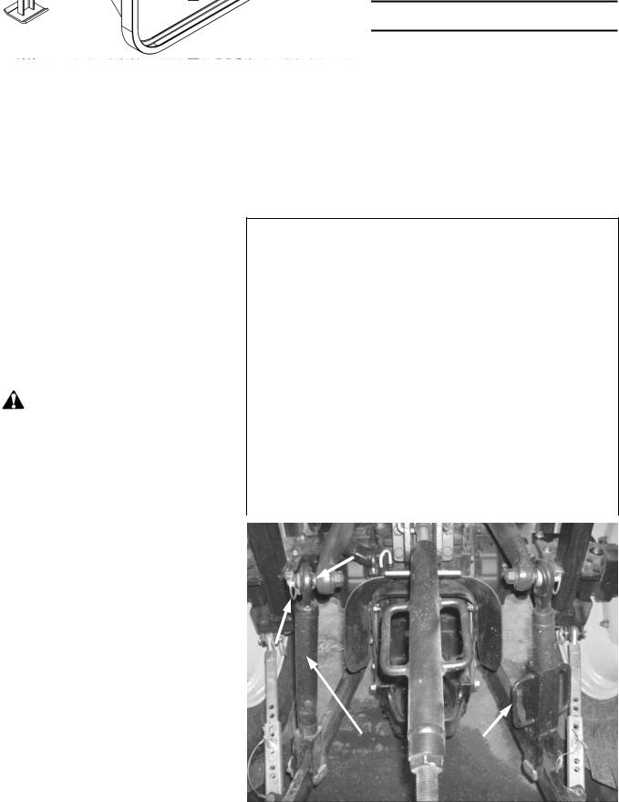
Adjusting the 3 Point Hitch |
|
|
|
|
|
|
|
|
|
|
|
|
|
|
Figure 2: Adjust the three point hitch |
|
|
|
|
|
|
|
|
|
|
|
|
|
|
at maximum height by screwing the |
|
2 |
|
|
|
|
|
|
|
|
|
|
|
|
right arm adjustable link to its |
|
|
|
|
|
|
|
|
|
|
|
|
|
|
|
|
|
|
|
|
|
|
|
|
|
|
|
||
maximum using the handle (item 1). |
|
|
|
|
|
|
|
|
|
|
|
|
|
|
For the left arm, remove the linchpin |
|
|
|
|
|
|
|
|
|
|
|
|
|
|
(item 2) and remove the adjustable |
|
|
|
|
|
|
|
|
|
|
|
|
|
|
link (item 3) from the upper |
|
|
|
|
|
|
|
|
|
|
|
|
|
|
anchoring point (item 4). Screw the |
|
3 |
|
|
1 |
|
|
|
|
|
||||
adjustable link (item 3) to the |
|
|
|
|
|
|
|
|
|
|
|
|
|
|
|
|
|
|
|
|
|
|
|
|
|
|
|
||
maximum and reinstall. Make sure |
|
|
|
|
|
|
|
|
|
Figure 2 |
|
|
||
the two lower arms are at the same |
|
|
|
|
|
|
|
|
|
|
|
|
|
|
|
|
|
|
|
|
|
|
|
|
|
|
|
||
height. |
|
|
|
|
|
|
|
|
|
|
|
|
|
|
|
|
|
|
|
|
|
|
|
|
|
|
|
|
|
OM 0399HP-A |
|
12 |
|
|
|
|
|
|
|
|
|
|
||

ASSEMBLY
Installation of the Quick Couplers
3X20 TRACTOR
Front support - fig.3
1. Install two 1 1/16"JIC x 3/4"NPT bulkhead adaptors (item 2) on the middle hose support (item 1) with
1 1/16" bulkhead nuts (item 3).
2.Install two 3/4"NPT x 1/2"NPT male adaptors (item 6) followed by a 1/2" male quick coupler, a 1/2" female quick coupler (item 4) with their respective dust plug and dust cap (item 5) in the order illustrated.
Rear support - fig.4 & 5
1.Install two 1 1/16"JIC x 3/4"NPT bulkhead adaptors (item 2) on the rear hose support (item 1) with 1 1/16" bulkhead nuts (item 3).
2.Install two 3/4"NPT x 1/2"NPT male adaptors (item 6) followed by a 1/2" male quick coupler, a 1/2" female quick coupler (item 4) with their respective dust plug and dust cap (item 5) in the order illustrated.
NOTE: Refer to figure 5 for the position of the quick couplers.
Tractor Legend:
3X20 = 3320, 3520, 3720
4X20 = 4120, 4320, 4520, 4720
Figure 3
Figure 4
Figure 5
OM 0399HP-A |
13 |

ASSEMBLY
4X20 TRACTOR
Front support – figure 6
1. Install two 1 1/16"JIC x 3/4"NPT bulkhead adaptors (item 2) on the middle hose support (item 1) with 1 1/16" bulkhead nuts (item 3).
2.With thread sealant, install a 3/4" male quick coupler and a 3/4" female quick coupler (item 4) with their respective dust plug and dust cap (item 5).
Rear support – figures 7 & 8
1.Install two 1 1/16"JIC x 3/4"NPT bulkhead adaptors (item 2) on the
rear hose support (item 1) with
1 1/16" bulkhead nuts (item 3).
2.With thread sealant, install a 3/4" male quick coupler, a 3/4" female quick coupler (item 4) with their respective dust plug and dust cap (item 5) in the order illustrated.
NOTE: Refer to figure 8 for the position of the quick couplers.
Figure 6
Figure 7
Figure 8
OM 0399HP-A |
14 |
ASSEMBLY
Installation of the Hose Supports
NOTE: Refer to the parts section on page 50 to identify the hose supports and to figure 9a for their exact location on the loader arm.
1.Figure 9: Attach the rear hose support (item 1) and the fastening bracket (item 2) to the left front loader arm (item 3) with two 5/16" NC x 1 1/4" lg bolts, 5/16" flat washers and 5/16" NC nylon insert nuts (items 4-14-5).
2.Figure 9: Attach the middle hose support (item 7) and its fastening bracket (item 6) with two 5/16" NC x 1 1/4" lg. bolts and two 5/16" NC nylon insert nuts (items 8-9).
3.Figures 9: Attach the lower part of the front hose support (item 10) and its fastening plate (item 11) with one 5/16"NC x 3 1/2" lg bolts and one 5/16" NC nylon insert nuts (items 12-13) and the upper part with 1/4"NC x 6" flattened bolt, a bushing and a 1/4"NC nut (items 15-16-17).
CAUTION: Do not cover the loader arm decals particularly with the front support (items 1011).
IMPORTANT - Detail A: Make sure the flattened portion of the 1/4"NC bolt faces the loader cylinder and is in a position that ensures the cylinder doesn't interfere with the bolt.
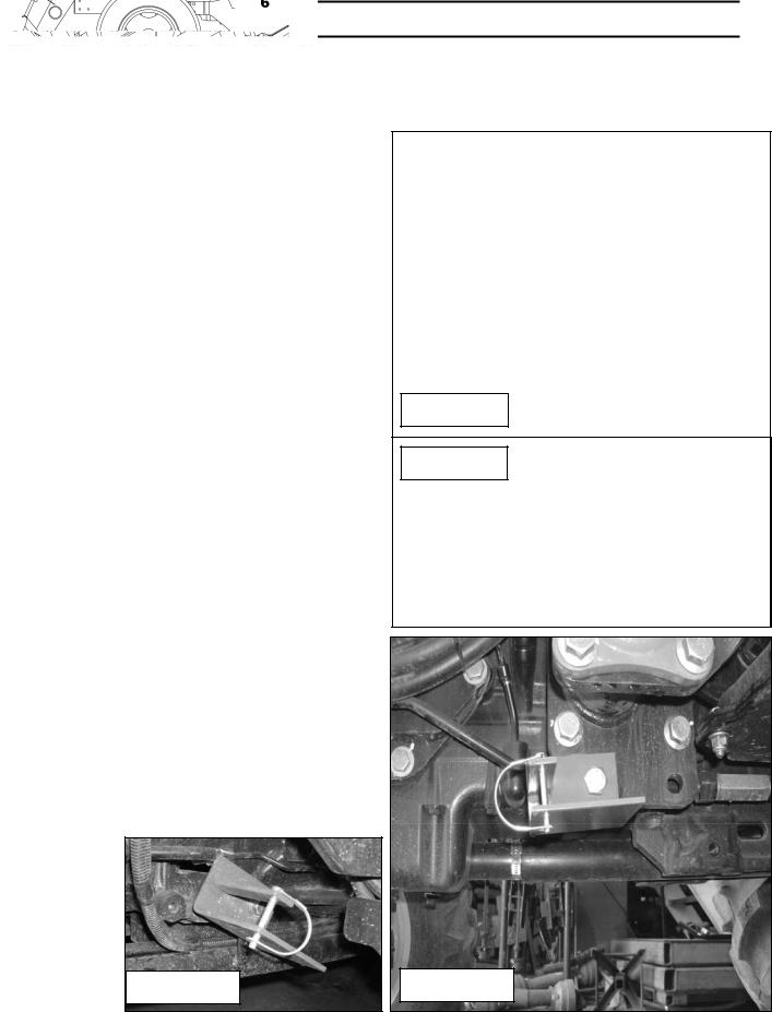
4.A- For 3X20 tractors - fig.10a:
Attach the hose support in the same location as the tractor hose support located under the left tractor step plate using the existing tractor bolt. Install the round wire lock pin in the support as shown.
On some tractor, it may be necessary to position the support with an angle as shown on fig.10a.
B- For 4X20 tractors - fig.10:
Attach the hose support (item 1) on the front loader support plate located under the step plate (item 2) with a 5/8" NC x 2" lg. bolt (item 3) and a 5/8" NC nylon insert nut (not illustrated). Install the round wire lock pin (item 4) in the holes of the support.
Figure 9
Figure 9a
Figure 10a
Figure 10
OM 0399HP-A |
15 |

ASSEMBLY
5.Run the hydraulic hoses from the rear of the tractor to the front without inserting them in the hose supports. The straight hose fittings go on the front of the tractor.
6.Figures 11: Connect the hoses (item 2) to the rear bulkhead adaptors (item 1).
7.A- Without cab: Figure 12:
-Remove the bolt and the flat washer that holds the left fender to the tractor frame.
-Insert a M10 x 1.5 x 60mm bolt (not illustrated) in the hole of the bent section of the fastening bracket (item 1).
-Insert the fastening bracket, from the front to the rear, around the tractor post (item 2) and secure with a M10 x 1.5 x 60mm bolt for the 4X20 or a M10 x 1.5 x 40mm bolt for the 3X20 (item 3), and the tractor flat washer previously removed, located between the bracket and the tractor aisle. DO NOT use this flat washer for the 3X20 tractor.
-After installing the hoses on the bulk head adaptors, attach the rear hose support (item 4) around the tractor post inserting the front part first and secure in place with a 3/8" flat washer (not illustrated) and a 10mm nylon insert nut (not illustrated).
-Attach the rear section with a 10mm nylon insert nut (item 5).
B- With cab: Figure 12A:
Attach the rear hose support (item 1) and it's fastening bracket (item 2) to the tractor post (item 3) at about 9" from the axle's upper plate for the 3X20 series and at 6 3/4" for the 4X20 series with two M10 x 1.5 x 60mm bolt, 3/8" flat washers and two 10mm nylon insert nut (items 4-5-6).
Figure 11
2
1
Figure 12
4 |
|
5 |
|
|
|
|
3X20: 9" |
6 |
|
|
|
|
4X20: 6 ¾" |
2 |
|
|
|
|
|
1 |
|
3 |
|
|
|
Figure 12A |
OM 0399HP-A |
16 |
 Loading...