


OPERATOR’S MANUAL
RB1172
RB1184
RB1196
REAR BLADES
5WPMAN0148 (Rev. 2/16/2009)

TO THE DEALER:
Assembly and proper installation of this product is the responsibility of the Frontier dealer. Read manual instructions
and safety rules. Make sure all items on the Dealer’s Pre-Delivery and Delivery Check Lists in the Operator’s Manual
are completed before releasing equipment to the owner.
TO THE OWNER:
Read this manual before operating your Frontier equipment. The information presented will prepare you to do a better
and safer job. Keep this manual handy for ready reference. Require all operators to read this manual carefully and
become acquainted with all the adjustment and operating procedures before attempting to operate. Replacement
manuals can be obtained from your selling dealer.
The equipment you have purchased has been carefully engineered and manufactured to provide dependable and
satisfactory use. Like all mechanical products, it will require cleaning and upkeep. Lubricate the unit as specified.
Observe all safety information in this manual and safety decals on the equipment.
For service, your authorized Frontier dealer has trained mechanics, genuine Frontier service parts, and the necessary
tools and equipment to handle all your needs.
Use only genuine Frontier service parts. Substitute parts will void the warranty and may not meet standards required for
safe and satisfactory operation. Record the model number and serial number of your equipment in the spaces
provided:
Model: ______________________________ Date of Purchase: _____________________
Serial Number: (see Safety Decal section for location) ____________________________________
Provide this information to your dealer to obtain correct repair parts.
Throughout this manual, the term NOTICE is used to indicate that failure to observe can cause damage to equipment.
The terms CAUTION, WARNING and DANGER are used in conjunction with the Safety-Alert Symbol, (a triangle with
an exclamation mark), to indicate the degree of hazard for items of personal safety.
2 Introduction
Frontier (Rev. 2/4/2009)

TABLE OF CONTENTS
Si no lee Ingles, pida ayuda a
alguien que si lo lea para que le
traduzca las medidas de seguridad.
LEA EL INSTRUCTIVO!
!
WARNING
INTRODUCTION . . . . . . . . . . . . . . . . . . . . . . . . . . . . . . . . . . . . . . . . . . . . . . 2
GENERAL INFORMATION . . . . . . . . . . . . . . . . . . . . . . . . . . . . . . . . . . . . . . 3
SPECIFICATIONS. . . . . . . . . . . . . . . . . . . . . . . . . . . . . . . . . . . . . . . . . . . . . 4
SAFETY RULES . . . . . . . . . . . . . . . . . . . . . . . . . . . . . . . . . . . . . . . . . . . . . . 5
SAFETY DECALS . . . . . . . . . . . . . . . . . . . . . . . . . . . . . . . . . . . . . . . . . . . . . 7
OPERATION . . . . . . . . . . . . . . . . . . . . . . . . . . . . . . . . . . . . . . . . . . . . . . . . . 9
OPTIONAL EQUIPMENT . . . . . . . . . . . . . . . . . . . . . . . . . . . . . . . . . . . . . . 13
DEALER CHECK LISTS . . . . . . . . . . . . . . . . . . . . . . . . . . . . . . . . . . . . . . . 15
OWNER SERVICE . . . . . . . . . . . . . . . . . . . . . . . . . . . . . . . . . . . . . . . . . . . 16
PARTS LIST INDEX . . . . . . . . . . . . . . . . . . . . . . . . . . . . . . . . . . . . . . . . . . 17
BOLT TORQUE CHART . . . . . . . . . . . . . . . . . . . . . . . . . . . . . . . . . . . . . . . 22
BOLT SIZE CHART & ABBREVIATIONS . . . . . . . . . . . . . . . . . . . . . . . . . . 23
GENERAL INFORMATION
The purpose of this manual is to assist you in operating
and maintaining your Rear Blade. Read it carefully. It
furnishes information and instructions that will help you
achieve years of dependable performance. These
instructions have been compiled from extensive field
experience and engineering data. Some information
may be general in nature, due to unknown and varying
operating conditions. However, through experience
and these instructions, you should be able to develop
procedures suitable to your particular situation.
The illustrations and data used in this manual were current at the time of printing. However, due to possible
inline production changes, your machine may vary
slightly in detail. We reserve the right to redesign and
5WPMAN0148 (Rev. 2/16/2009)
change the machines as may be necessary without
notification.
Some illustrations in this manual show the
equipment with safety shields removed to provide
a better view. This equipment should never be
operated with any necessary safety shielding
removed.
Throughout this manual, references are made to right
and left directions. These are determined by standing
behind the tractor facing the direction of forward travel.
Introduction 3

SPECIFICATIONS
RB1172 RB1184 RB1196
Overall Height 40" (102 cm) 40" (102 cm) 40" (102 cm)
Moldboard Height 18" (46 cm) 18" (46 cm) 18" (46 cm)
Working Width 72" (183 cm) 84" (213 cm) 96" (244 cm)
Moldboard Thickness 5/16" (7.9 mm) 5/16" (7.9 mm) 5/16" (7.9 mm)
Overall Depth 50" (127 cm) 50" (127 cm) 50" (127 cm)
Weight 530 lbs. (240 kg) 565 lbs. (256 kg) 600 lbs. (272 kg)
Cutting Edge 1/2" x 6" 1/2" x 6" 1/2" x 6"
(1.3 x 15 cm) (1.3 x 15 cm) (1.3 x 15 cm)
Reversible Reversible Reversible
Offset Position Left or Right 4", 10", 16" 4", 10", 16" 4", 10", 16"
(10, 25, 41 cm) (10, 25, 41 cm) (10, 25, 41 cm)
No. of Forward Positions 9 9 9
No. of Backfill Positions 9 9 9
No. of Tilt Positions 5 5 5
Tractor 3-Point Cat 1 or 2 Cat 1 or 2 Cat 1 or 2
Quick Hitch (Optional) Cat 1 or 2 Cat 1 or 2 Cat 1 or 2
Implement Code
for Tractor Ballast 36.4 38.8 41.2
Tractor HP Rating 75 HP max 75 HP max 75 HP max
(56 kW) (56 kW) (56 kW)
NOTES
4 Introduction
5WPMAN0148 (Rev. 2/16/2009)

Safety is a primary concern in the design and
manufacture of our products. Unfortunately, our
efforts to provide safe equipment can be wiped
out by an operator’s single careless act.
In addition to the design and configuration of
equipment, hazard control and accident prevention are dependent upon the awareness, concern,
judgement, and proper training of personnel
involved in the operation, transport, maintenance
and storage of equipment.
It has been said “The best safety device is an
informed, careful operator.” We ask you to be that
kind of operator.
ATTENTION! BECOME ALERT! YOUR SAFETY IS INVOLVED!
TRAINING
Safety instructions are important! Read all
attachment and power unit manuals; follow all
safety rules and safety decal information. (Replacement manuals and safety decals are available from
your dealer.) Failure to follow instructions or safety
rules can result in serious injury or death.
If you do not understand any part of this manual
and need assistance, see your dealer.
Know your controls and how to stop engine and
attachment quickly in an emergency.
Operators must be instructed in and be capable
of the safe operation of the equipment, its attachments, and all controls. Do not allow anyone to
operate this equipment without proper instructions.
Keep hands and body away from pressurized
lines. Use paper or cardboard, not hands or other
body parts to check for leaks. Wear safety goggles.
Hydraulic fluid under pressure can easily penetrate
skin and will cause serious injury or death.
Make sure that all operating and service person-
nel know that if hydraulic fluid penetrates skin, it
must be surgically removed as soon as possible by
a doctor familiar with this form of injury or gangrene, serious injury, or death will result. CONTACT A PHYSICIAN IMMEDIATELY IF FLUID
ENTERS SKIN OR EYES. DO NOT DELAY.
Never allow children or untrained persons to
operate equipment.
Frontier RB1172 (Rev. 6/15/2006)
SAFETY RULES
PREPARATION
Check that all hardware is properly installed.
Always tighten to torque chart specifications
unless instructed otherwise in this manual.
Always wear relatively tight and belted clothing
to avoid getting caught in moving parts. Wear
sturdy, rough-soled work shoes and protective
equipment for eyes, hair, hands, hearing, and head;
and respirator or filter mask where appropriate.
Make sure attachment is properly secured,
adjusted, and in good operating condition.
Power unit must be equipped with ROPS or
ROPS cab and seat belt. Keep seat belt securely
fastened. Falling off power unit can result in death
from being run over or crushed. Keep foldable
ROPS system in “locked up” position at all times.
Make sure all safety decals are installed.
Replace if damaged. (See Safety Decals section for
location.)
A minimum 20% of tractor and equipment
weight must be on the tractor front wheels when
attachments are in transport position. Without this
weight, tractor could tip over, causing personal
injury or death. The weight may be attained with a
loader, front wheel weights, ballast in tires or front
tractor weights. Weigh the tractor and equipment.
Do not estimate.
OPERATION
Do not allow bystanders in the area when operating, attaching, removing, assembling, or servicing equipment.
Do not operate or transport equipment while
under the influence of alcohol or drugs.
Operate only in daylight or good artificial light.
Keep hands, feet, hair, and clothing away from
equipment while engine is running. Stay clear of all
moving parts.
Always comply with all state and local lighting
and marking requirements.
Never allow riders on power unit or attachment.
Always sit in power unit seat when operating
controls or starting engine. Securely fasten seat
belt, place transmission in neutral, engage brake,
and ensure all other controls are disengaged
before starting power unit engine.
(Safety Rules continued on next page)
Safety 5

(Safety Rules continued from previous page)
SAFETY RULES
ATTENTION! BECOME ALERT! YOUR SAFETY IS INVOLVED!
Look down and to the rear and make sure area
is clear before operating in reverse.
Do not operate or transport on steep slopes.
Do not stop, start, or change directions sud-
denly on slopes.
Use extreme care and reduce ground speed on
slopes and rough terrain.
Watch for hidden hazards on the terrain during
operation.
Stop power unit and equipment immediately
upon striking an obstruction. Turn off engine,
remove key, inspect, and repair any damage before
resuming operation.
to drop or rotate unexpectedly and cause severe
injury or death.
• Service work does not require going underneath.
• Read Operator's Manual for service instructions or have service performed by a qualified
dealer.
Always wear relatively tight and belted clothing
to avoid getting caught in moving parts. Wear
sturdy, rough-soled work shoes and protective
equipment for eyes, hair, hands, hearing, and head;
and respirator or filter mask where appropriate.
Make sure attachment is properly secured,
adjusted, and in good operating condition.
Before transporting, pivot the unit so red reflectors face the rear.
MAINTENANCE
Before dismounting power unit or performing
any service or maintenance, follow these steps:
disengage power to equipment, lower the 3-point
hitch and all raised components to the ground,
operate valve levers to release any hydraulic pressure, set parking brake, stop engine, remove key,
and unfasten seat belt.
NEVER GO UNDERNEATH EQUIPMENT. Never
place any part of the body underneath equipment
or between moveable parts even when the engine
has been turned off. Hydraulic system leak-down,
hydraulic system failures, mechanical failures, or
movement of control levers can cause equipment
Keep all persons away from operator control
area while performing adjustments, service, or
maintenance.
Tighten all bolts, nuts, and screws to torque
chart specifications. Check that all cotter pins are
installed securely to ensure equipment is in a safe
condition before putting unit into service.
Make sure all safety decals are installed.
Replace if damaged. (See Safety Decals section for
location.)
STORAGE
Block equipment securely for storage.
Keep children and bystanders away from stor-
age area.
6 Safety
Frontier RB1172 (Rev. 6/15/2006)

4 - Serial Number Plate
1 – 5WP57503
WARNING
55121--C
FALLING OFF CAN RESULT IN BEING RUN OVER.
Tractor must be equipped with ROPS (or ROPS CAB) and
seat belt. Keep foldable ROPS systems in “locked up”
position at all times.
Buckle Up! Keep seat belt securely fastened.
Allow no riders.
RAISED IMPLEMENT CAN DROP AND CRUSH.
Never go underneath raised implement which can drop
from equipment or tractor 3-point hitch hydraulic leak
down, hydraulic system failures, movement of control
levers or mechanical linkage failures.
Service work does not require going underneath
implement. Read manual instructions.
FALLING OFF OR GOING UNDERNEATH IMPLEMENT
CAN RESULT IN SERIOUS INJURY OR DEATH.
2 – 5WP55121
LE NEX A, K S, U .S. A.
5 - 5WP1002940 Amber Reflector 9" (Front)
6 - 5WP57123 Red Reflector 9" (Rear)
(Safety Decals continued on next page)
SAFETY & INSTRUCTIONAL DECALS
ATTENTION! BECOME ALERT! YOUR SAFETY IS INVOLVED!
Replace Immediately If Damaged!
WARNING
BLADE MUST BE PROPERLY
SECURED OR IT WILL FALL OFF
WHEN ANGLING OR REVERSING.
Follow all manual instructions and
safety rules.
Lower blade to ground, shut off tractor,
set park brake, and remove key.
Check under center rear of blade to
make sure pivot nut and hitch pin are
in place as shown in pictorial.
If pivot nut and pin are missing, blade
will fall off when rotated. Do not rotate
or operate blade until pivot nut and
hitch pin are replaced.
FAILURE TO FOLLOW INSTRUCTIONS
CAN RESULT IN INJURY OR DEATH.
57503-A
PRODUCT IDENTIFICATION NUMBER
LENEXA, KS, U.S.A.
5WPMAN0148 (Rev. 5/16/2008)
Safety 7

SAFETY & INSTRUCTIONAL DECALS
Unit must not extend
more than 4 feet left of
center of the tractor when
driving on public roads.
WARNING
1003193-A
ATTENTION! BECOME ALERT! YOUR SAFETY IS INVOLVED!
Replace Immediately If Damaged!
(Safety Decals continued from previous page)
WARNING
TO AVOID SERIOUS
INJURY OR DEATH:
Read Operator's Manual
before operating, servicing,
or repairing equipment.
Follow all safety rules and
instructions. (Manuals are
available from your selling
dealer.)
Never allow riders.
Keep bystanders away from
equipment during operation.
Operate from tractor seat
only.
Keep all shields in place and
in good condition.
Lower equipment to ground,
stop engine, remove key,
and set brake before
dismounting tractor.
Never allow children or
untrained persons to
operate equipment.
FAILURE TO FOLLOW THESE
INSTRUCTIONS CAN RESULT
IN INJURY OR DEATH.
1003199
3 - 5WP1003199
7 - 5WP1003193
8 - 5WP1002941
WARNING
CRUSHING AND
PINCHING HAZARD
Be extremely careful
handling various parts of the
machine. They are heavy and
hands, fingers, feet, and
other body parts could be
crushed or pinched between
tractor and implement.
Operate tractor controls from
tractor seat only.
Do not stand between tractor
and implement when tractor
is in gear.
Make sure parking brake is
engaged before going
between tractor and
implement.
Stand clear of machine while
in operation or when it is
being raised or lowered.
FAILURE TO FOLLOW THESE
INSTRUCTIONS COULD
RESULT IN SERIOUS INJURY
OR DEATH.
1002941-A
Use a clean, damp cloth to clean safety decals.
Avoid spraying too close to decals when using a pressure washer;
high-pressure water can enter through very small scratches or
under edges of decals causing them to peel or come off.
Replacement safety decals can be ordered free from your dealer.
8 Safety
BE CAREFUL!
5WPMAN0148 (Rev. 5/16/2008)

OPERATION
WARNING
CAUTIONCAUTION
The operator is responsible for the safe operation of
this equipment. Operators must be instructed in and be
capable of the safe operation of the equipment, its
attachments and all controls. Do not allow anyone to
operate this equipment without proper instructions.
The Rear Blade is designed for a wide range of applications. The Rear Blade may be used for scraping, leveling, grading and backfilling and may be angled to
windrow debris to the side for removal.
Optional kits are also available and included in this
manual. The Single Tailwheel Kit is useful for grading
and leveling work. The Skid Shoe Kit helps control cutting height when operating on hardened surfaces.
PRE-OPERATION CHECK LIST
(OWNER’S RESPONSIBILITY)
___ Check that all hardware is properly installed and
secured.
___ Do not allow riders.
Always wear relatively tight and belted clothing
to avoid getting caught in moving parts. Wear
sturdy, rough-soled work shoes and protective
equipment for eyes, hair, hands, hearing, and head;
and respirator or filter mask where appropriate.
CONNECTING REAR BLADE TO
TRACTOR
Rear blades are shipped completely assembled and
may be installed on tractors equipped with a Category
1 or Category 2 3-point hitch.
The tractor draw bar must be removed or installed in its
shortest position to allow the blade to rotate 180
degrees.
___ Review and follow all safety rules and safety
decal instructions on page 5 through page 8.
___ Check that equipment is properly and securely
attached to tractor.
___ Make sure tractor ROPS or ROPS CAB and seat
belt are in good condition. Keep seat belt
securely fastened during operation.
___ Check that all safety decals are installed and in
good condition. Replace if needed.
Never allow children or untrained persons to
operate equipment.
Keep bystanders away from equipment.
Keep all persons away from operator control
area while performing adjustments, service, or
maintenance.
Never allow riders on power unit or attachment.
A minimum 20% of tractor and equipment
weight must be on the tractor front wheels when
attachments are in transport position. Without this
weight, tractor could tip over, causing personal
injury or death. The weight may be attained with a
loader, front wheel weights, ballast in tires or front
tractor weights. Weigh the tractor and equipment.
Do not estimate.
1. 3-Point lower lift arm
2. Tractor top link
3. Retaining pin
4. Top link clevis pin
5. 3-Point lower lift arm sway chain
6. Klik pin
Figure 1. Connecting Rear Blade to Tractor
Refer to Figure 1. Place tractor 3-point lower lift arms
(1) in the correct hitch position and install Klik pins (6)
as shown (also refer to Figure 2). Category 1 tractor lift
arms use inner hitch position. Category 2 tractor lift
arms use outer hitch position with adapter sleeves
installed over mounting pins. Secure lower link pins
with lynch pins.
Attach tractor top link (2) to top hole of the A-frame and
secure with the high strength clevis pin (4) and retaining pin (3) provided with top link. Category 1 top link
attaches to front hole and Category 2 top link attaches
to rear hole.
5WPMAN0148 (Rev. 5/16/2008)
Operation 9

Adjust sway blocks or tighten tractor 3-point sway
WARNING
chains to eliminate implement side-to-side movement
during operation.
Figure 2. Top Link Identification
Optional Quick Hitch Bushing Kit
An optional quick hitch bushing kit is available for Category 1 and Category 2 tractors. See page 14 for installation instructions.
Storage Position
With rear blade raised, place parking stand in lowest
position as shown in Figure 4. Lower rear blade so cutting edge and parking stand are flat on the ground. Disconnect 3-point arms and top link from rear blade.
Figure 4. Parking Stand in Storage Position
ADJUSTMENTS
NOTICE
Do not use Quick Hitch with Single Tailwheel
Kit.
Parking Stand Placement
Operating Position
Place parking stand in the raised position during operation. This position allows the moldboard to rotate 360
degrees. Secure into position with 3/8 x 2-1/4 lynch pin
as shown in Figure 3.
NEVER GO UNDERNEATH EQUIPMENT. Never
place any part of the body underneath equipment
or between moveable parts even when the engine
has been turned off. Hydraulic system leak-down,
hydraulic system failures, mechanical failures, or
movement of control levers can cause equipment
to drop or rotate unexpectedly and cause severe
injury or death.
• Service work does not require going underneath.
• Read Operator's Manual for service instructions or have service performed by a qualified
dealer.
Adjustments to the rear blade require raising the blade
slightly off of the ground. Do not leave the tractor operator position with the blade raised except to make
blade adjustments during operation.
To make blade adjustments, raise the blade just high
enough to allow blade to pivot without dragging on the
ground. Shut off the tractor engine, set the park brake,
remove the key, and carefully leave the operator position.
Figure 3. Parking Stand In Raised Position
10 Operation
Never place any part of your body underneath the
blade or 3-point hitch while making adjustments.
Hydraulic leak-down or failure can cause the blade to
fall suddenly.
5WPMAN0148 (Rev. 5/16/2008)

Angling and Reversing (Figure 5)
Ten holes are provided for angling the blade: five in the
forward position (to a maximum angle of 45 degrees)
and five in the reverse position. Lift the drop pins,
swing the blade to the desired angle or to the reverse
position, then reinsert the drop pins to lock the blade in
place.
age in place by inserting the pin in the desired hole.
Secure with hair pin clip. For offsetting to the left, position the linkage on the right side of the frame and
extend the linkage.
Figure 7. Rear Blade Offset Right
Figure 5. Angling and Reversing
Frame Offset (Figure 6 & Figure 7)
The frame will swing to the right or left. For offsetting
the frame to the right, position the standard mechanical
linkage (1) on the left side of the frame.
Blade Pitch
The pitch of the blade can be changed by adjusting the
top link of the tractor.
Blade Tilt (Figure 8)
The blade will tilt so that one end of the moldboard is
lower than the other. Remove yoke pin (1), tilt the blade
to the desired angle, replace the pin, and secure with
the hair pin clip. Additional tilt adjustment can be made
with the tractor 3-point hitch leveling crank.
1. Mechanical linkage
2. Centering pin
Figure 6. Rear Blade Centered
Extend the linkage by pulling the center pin (2) and
swinging the frame to the desired angle. Lock the link-
5WPMAN0148 (Rev. 5/16/2008)
1. Yoke pin
Figure 8. Blade Tilt
Operation 11

Blade Rotation (Figure 9)
The blade can be reversed for backfilling. Remove the
drop pins and rotate the blade 180 degrees from the
forward position. Reinstall the drop pins and secure.
The tractor draw bar must be removed or installed in its
shortest position to allow the blade to rotate 180
degrees.
Adjust sway blocks or tighten tractor 3-point sway
chains to eliminate implement side-to-side movement
during operation.
NOTES
NOTES
Figure 9. Blade Rotated 180 Degrees
12 Operation
5WPMAN0148 (Rev. 5/16/2008)
OPTIONAL EQUIPMENT
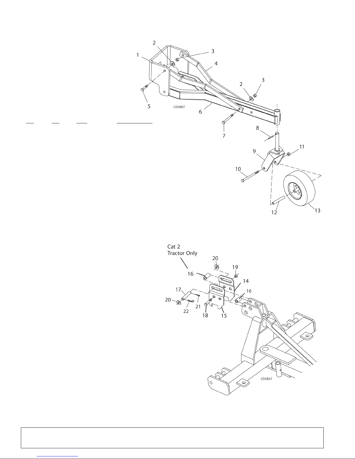
1. Tailwheel
tube assembly
2. Notat yoke assembly
3. 3/8" Spirol pin
4. 5/8" Hardened flat washer
(from turntable)
5. 5/8 NF x 1-1/2" Cap screw
(from turntable)
14. Right floating link
15. Left floating link
16. Sleeve .78 x 1.00 x 2.00"
17. Clevis pin .75 x 4.38"
18. 3/4 NC x 4-1/2" Cap
screw GR5
19. 3/4" NC Lock nut
20. 3/4" Flat washer
21. 3/16 x 1-1/2" Cotter pin
22. 5/32" Hair pin cotter
SINGLE TAILWHEEL KIT 5WP1001533
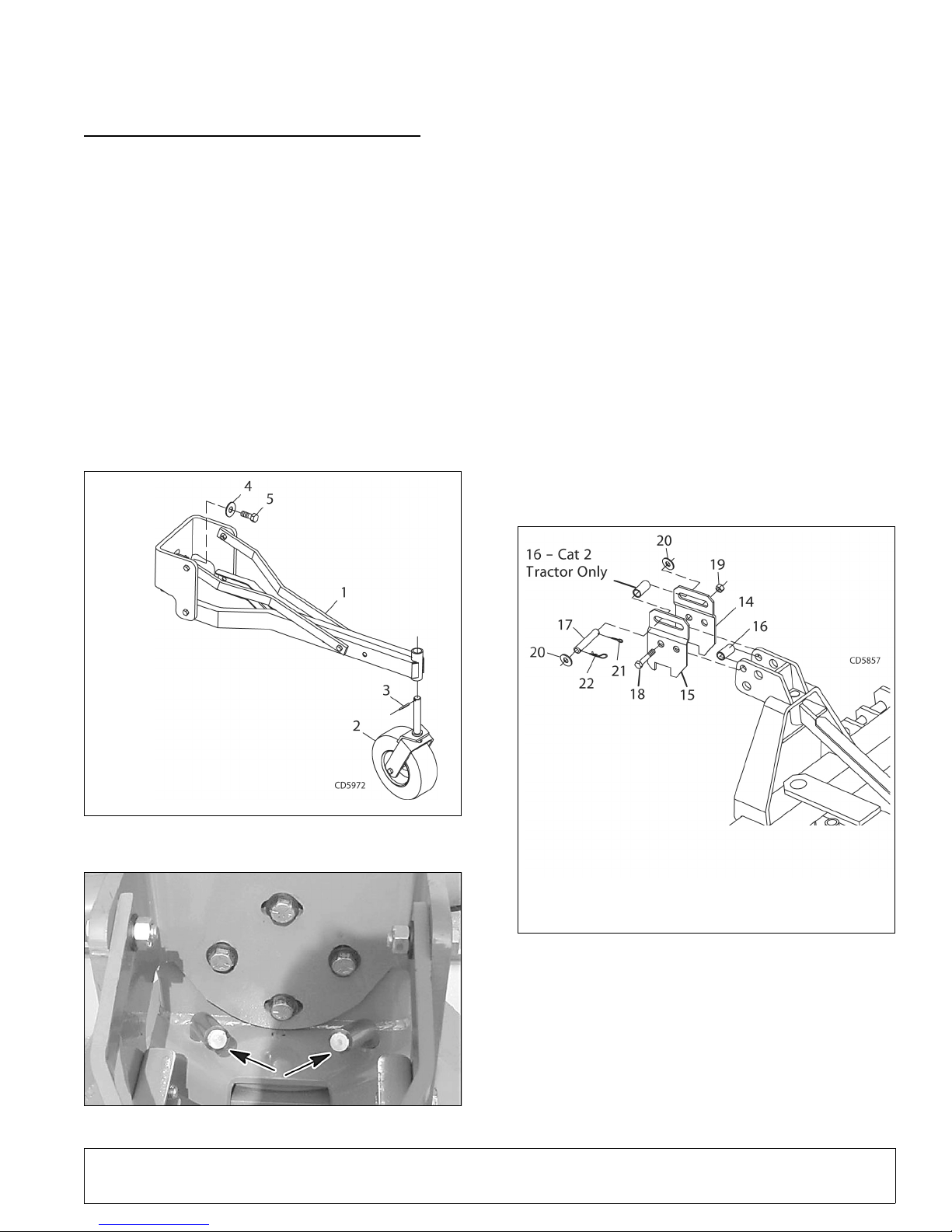
Assemble Tailwheel (Figure 10)
NOTICE
Floating links must be used with tailwheel to
avoid equipment damage.
Tailwheel kit will not function properly when
used with Quick Hitch.
Remove round retainer plate and hardware from rear of
tilt turntable of rear blade (refer to Figure 5).
NOTE: Point drop pins in tilt turntable towards center of
unit (Figure 11) before attaching tailwheel tube assembly.
Attach tailwheel tube assembly (1) to rear of tilt turntable and secure with cap screws (5) and hardened flat
washers (4) from turntable. Torque cap screws to 170
lbs-ft. (231 N-m).
Attach yoke assembly (2) to tailwheel tube and secure
into position with spirol pin (3).
Assemble Floating Link (Figure 12)
Attach right and left floating link brackets (14, 15) with
offset to the inside on each side of the A-frame. Place
sleeve (16) in forward hole and secure assembly into
position using two cap screws (18) and lock nuts (19)
as shown in Figure 12.
NOTE: When attaching to tractor, install clevis pin (17)
into floating links using two 3/4" washers (20), one cotter pin (21), and hair pin (22) as shown.
Figure 10. Tailwheel Assembly
5WPMAN0148 (Rev. 5/16/2008)
Figure 11. Drop Pin Position
Figure 12. Floating Link Installation
Adjust Tailwheel Assembly
Set blade cutting edge 1/2" (13 mm) above the ground
with the tractor 3-point hitch. Adjust tail wheel until tire
is on the ground and the top link pin is centered in the
floating link slot. Fine tune the grading height by raising
or lowering the 3-point hitch.
Optional Equipment 13

QUICK HITCH BUSHING KIT 5WP1002011
1. A-Frame assembly
2. Sleeve, .94 x 1.44 x 2.75 Cat 2
3. Sleeve, .94 x 1.44 x 2.19 Cat 1
4. Sleeve, 1.0 x 1.25 x 2.06
5. 1.0 NC x 5.0 Cap screw GR5
6. 1.0 Lock washer
7. 1.0 NC Hex nut
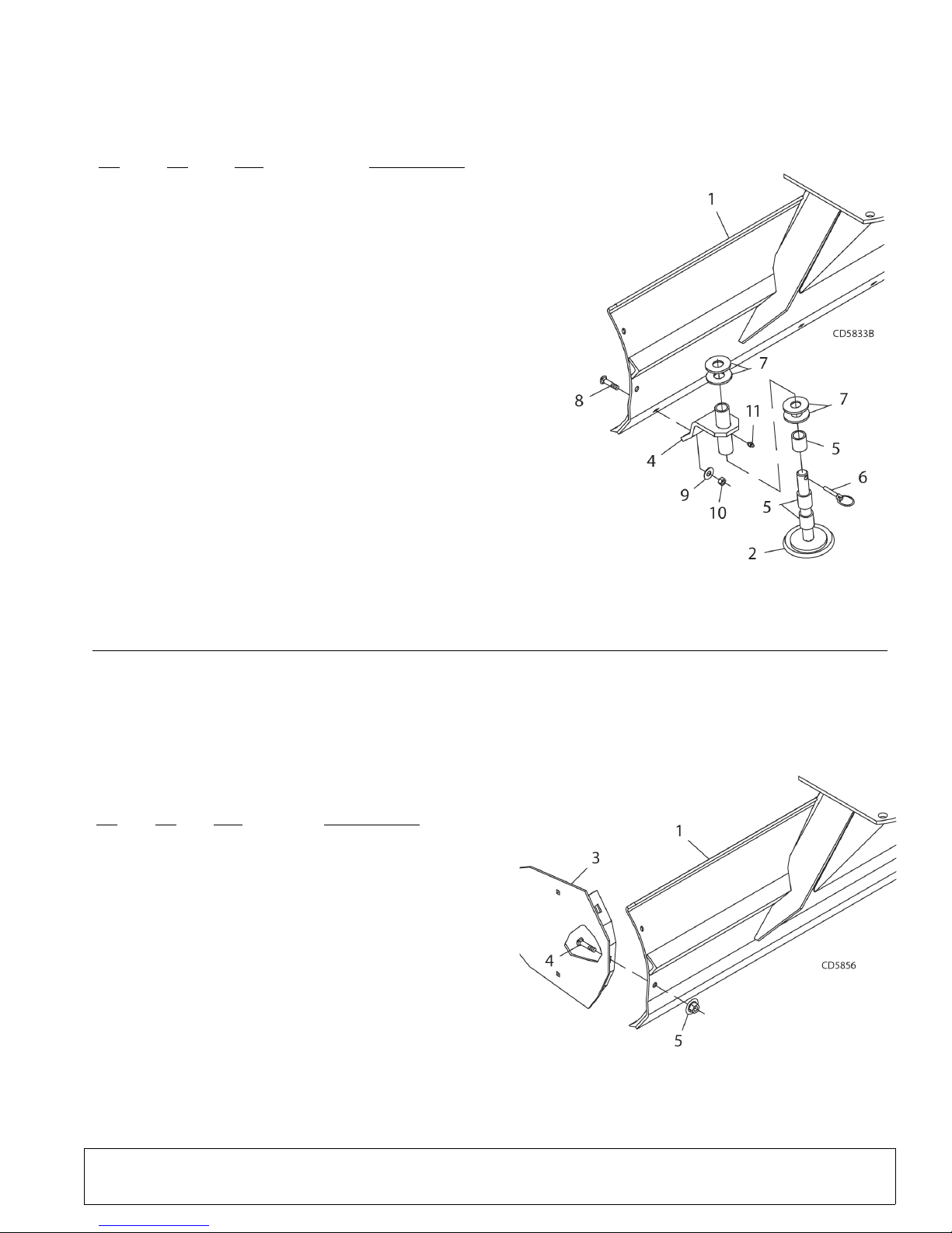
1. Moldboard assembly
2. Skid & shaft assembly
3. Right skid shoe bracket
(not shown)
4. Left skid shoe
bracket
5. Spacer, 1-1/4
sch 80 x 3/4" pipe
6. Pin, Klik 7/16 x 2"
7. 1-1/4" Standard flat washer
8. Plow bolt, 5/8 NC x 2-1/2"
9. 5/8" Standard flat washer
10. 5/8" NC Hex lock nut
11. Grease fitting
1. Moldboard assembly
2. End plate (right, not shown)
3. End plate (left)
4. 1/2 NC x 1-1/4" Carriage bolt
5. 1/2 NC Flanged lock nut
NOTICE
Do not use Quick Hitch with Single Tailwheel
Kit.
Install cap screw (5), sleeve (4), lock washer (6), and
hex nut (7) through bottom hole of A-frame as shown.
Install sleeves (2) for Category 2 tractors in outer pin
locations. Install sleeves (3) for Category 1 tractors in
inner pin locations as shown.
Figure 13. Quick Hitch Bushing Installation
SKID SHOE KIT 5WP18300 (Figure 14)
Remove plow bolts from each end of cutting edge.
Attach right and left skid shoe brackets (3 & 4) to rear
of moldboard with plow bolts (8), washers (9), and lock
nuts (10) supplied in kit. Top of skid shoe brackets
should angle slightly toward outer edge of blade.
Figure 14. Skid Shoe Installation
END PLATE KIT 5WP1001531 (Figure 15)
Install one end plate to each end of rear blade using
two carriage bolts (4) and flanged lock nuts (5) on each
end plate.
Adjust skid shoe to desired height using washers (7)
and spacers (5). One washer must be installed
between the shoe bracket and the spacers.
Make sure skid shoe rotates freely to prevent premature skid pad wear.
14 Optional Equipment
Figure 15. End Plate Installation
5WPMAN0148 (Rev. 5/16/2008)

DEALER CHECK LISTS
PRE-DELIVERY CHECK LIST
(DEALER’S RESPONSIBILITY)
Inspect the equipment thoroughly after assembly to be
certain it is set up properly before delivering it to the
customer. The following check list is a reminder of
points to inspect. Check off each item if it is found satisfactory or after proper adjustment is made.
___ Check that all safety decals are installed and in
good condition. Replace if damaged.
___ Check all bolts to be sure they are tight.
___ Check that all cotter pins and safety pins are
properly installed.
DELIVERY CHECK LIST
(DEALER’S RESPONSIBILITY)
___ Show customer the safe and proper procedures
to be used when mounting, dismounting and storing equipment.
___ For mounted units, add wheel weights, ballast in
front tires, and/or front tractor weight to enhance
front end stability. A minimum 20% of tractor and
equipment gross weight must be on front tractor
wheels. When adding weight to attain 20% of
tractor and equipment weight on front tractor
wheels, you must not exceed the ROPS weight
certification. Weigh the tractor and equipment. Do
not estimate!
___ Show customer how to make adjustments.
___ Present Operator's Manual and request that cus-
tomer and all operators read it before operating
equipment. Point out the manual safety rules,
explain their meanings, and emphasize the
increased safety hazards that exist when safety
rules are not followed.
___ Point out the safety decals. Explain their meaning
and the need to keep them in place and in good
condition. Emphasize the increased safety hazards when instructions are not followed.
___ Explain to customer the potential crushing haz-
ards of going underneath raised equipment.
Instruct customer that service work does not
require going underneath unit and never to do so.
5WPMAN0148 (Rev. 5/16/2008)
Dealer Check Lists 15

OWNER SERVICE
WARNING
CAUTIONCAUTION
The information in this section is written for operators
who possess basic mechanical skills. Should you need
help, your dealer has trained service technicians available. For your protection, read and follow all safety
information in this manual.
NEVER GO UNDERNEATH EQUIPMENT. Never
place any part of the body underneath equipment
or between moveable parts even when the engine
has been turned off. Hydraulic system leak-down,
hydraulic system failures, mechanical failures, or
movement of control levers can cause equipment
to drop or rotate unexpectedly and cause severe
injury or death.
• Service work does not require going underneath.
• Read Operator's Manual for service instructions or have service performed by a qualified
dealer.
Before dismounting power unit or performing
any service or maintenance, follow these steps:
disengage power to equipment, lower the 3-point
hitch and all raised components to the ground,
operate valve levers to release any hydraulic pressure, set parking brake, stop engine, remove key,
and unfasten seat belt.
Keep all persons away from operator control
area while performing adjustments, service, or
maintenance.
BLADE CUTTING EDGE REPLACEMENT
The moldboard blade is reversible and replaceable.
Remove the cap screws and hex nuts retaining the cutting edge to the moldboard. You may either replace or
reverse the cutting edge. Secure new or reversed cutting edge with cap screws and hex nuts previously
removed.
CLEANING
After Each Use
• Remove large debris such as clumps of dirt, grass,
crop residue, etc. from machine.
• Inspect machine and replace worn or damaged
parts.
• Replace any safety decals that are missing or not
readable.
Periodically or Before Extended Storage
• Clean large debris such as clumps of dirt, grass,
crop residue, etc. from machine.
• Remove the remainder using a low-pressure water
spray.
1. Be careful when spraying near scratched or torn
safety decals or near edges of decals as water
spray can peel decal off surface.
2. Be careful when spraying near chipped or
scratched paint as water spray can lift paint.
3. If a pressure washer is used, follow the advice of
the pressure washer manufacturer.
Always wear relatively tight and belted clothing
to avoid getting caught in moving parts. Wear
sturdy, rough-soled work shoes and protective
equipment for eyes, hair, hands, hearing, and head;
and respirator or filter mask where appropriate.
16 Owner Service
• Inspect machine and replace worn or damaged
parts.
• Sand down scratches and the edges of areas of
missing paint and coat with spray paint of matching
color (purchase from your dealer).
• Replace any safety decals that are missing or not
readable (supplied free by your dealer). See Safety
Decals section for location drawing.
5WPMAN0148 (Rev. 5/16/2008)

Rear Blades:
RB1172
RB1184
RB1196
PARTS INDEX
RB1172, RB1184, RB1196 Assembly . . . . . . . . . . . . . . . . . . . 18-19
Quick Hitch Bushing Kit (Optional) . . . . . . . . . . . . . . . . . . . . . . . . 19
Tailwheel Kit (Optional) . . . . . . . . . . . . . . . . . . . . . . . . . . . . . . . . . 20
Skid Shoe Assembly (Optional). . . . . . . . . . . . . . . . . . . . . . . . . . . 21
End Plate Kit (Optional) . . . . . . . . . . . . . . . . . . . . . . . . . . . . . . . . . 21
5WPMAN0148 (Rev. 5/16/2008)
Parts 17

RB1172, RB1184, RB1196 ASSEMBLY
27 - SAFETY DECAL SET
30 - COMPLETE DECAL SET
18 Parts
5WPMAN0148 (Rev. 5/16/2008)

RB1172, RB1184, RB1196 PARTS LIST
QUICK HITCH BUSHING KIT 5WP1002011
(OPTIONAL)
REF PART QTY DESCRIPTION
1 ---------------- 1 A-Frame Assembly
2 5WP1002012 2 Sleeve, .94 x 1.44 x 2.75 Cat 2
3 5WP1002013 2 Sleeve, .94 x 1.44 x 2.19 Cat 1
4 5WP1002014 1 Sleeve, 1.0 x 1.25 x 2.06
5 * 1 1.0 NC x 5.0 Cap Screw GR5
6 * 1 1.0 Lock Washer
7 * 1 1.0 NC Hex Nut
* Standard hardware; obtain locally
REF
NO
1 5WP1026709 1 1 1 A-Frame with decals
2 5WPHBL228 1 1 1 Pin, Clevis 1.00 x 5.00
3 5WP216241 1 1 1 Bolt, HH 1 In NC x 7 GR8
4 * 4 4 4 Washer, Flat 1 In Standard
6 5WP34279 2 2 2 Nut, Lock 1 In NC
8 5WP27542 4 4 4 Pin, Klik 7/16 x 2
9 5WPHBL233 2 2 2 Pin, Headless .88 x 6.94
10 5WPHBL225 3 3 3 Pin, Clevis 1.00 x 2.60
11 * 1 1 1 Pin, Safety 3/16
12 5WPHBL222 1 1 1 Link, Male
13 5WPHBL223 1 1 1 Link, Female
14 5WPHBL227 1 1 1 Pin, Bent .75 x 3.50
15 5WPHBL226 2 2 2 Pin, Bent 1.00 x 2.50
16 5WP1026708 1 1 1 Tilt Turntable with decals
17 5WP57817 4 4 4 Washer, Flat 5/8 SAE Hardened
18 5WP300461 4 4 4 Screw, HHCS 5/8 NF x 1-1/2 GR5
19 5WP53500 1 1 1 Plate, Retainer
20 5WP1026707 1 - - RB1172 Moldboard with decals
20 5WP1026706 - 1 - RB1184 Moldboard with decals
20 5WP1026705 - - 1 RB1196 Moldboard with decals
21 5WP26920 6 7 8 Bolt, Plow 5/8 NC x 1-3/4
22 * 6 7 8 Nut, Lock 5/8 NC
23 5WPFA503 1 1 1 Screw, HHCS 1 NC x 3 GR8
24 5WPHBL210 1 1 1 Frame Tube Assembly
25 5WP25258 1 - - Cutting Edge, 72 In (12" bolt centers)
25 5WP46440 - 1 - Cutting Edge, 84 In (12" bolt centers)
25 5WP25270 - - 1 Cutting Edge, 96 In (12" bolt centers)
26 5WP56598 2 2 2 Sleeve, .88 x 1.13 x 2.62
27 5WP1002955 1 1 1 Decal Set, Safety RB1172/84/96
28 5WP55011 1 1 1 Stand Assembly
29 5WP33000 1 1 1 Pin, Lynch 3/8 x 2-1/4
30 5WP1002956 1 1 1 Decal Set, Complete RB1172/84/96
PART
NO
QTY
RB1172
QTY
RB1184
QTY
RB1196
DESCRIPTION
* Standard hardware; obtain locally
(Rev. 2/16/2009)
5WPMAN0148 (Rev. 5/16/2008)
Parts 19
TAILWHEEL KIT 5WP1001533 (OPTIONAL)
REF
NO
PA RT
NO
QTY DESCRIPTION
1 5WP1001530 1 Plate, Tailwheel Retainer
2 5WP57817 5 Washer, Flat 5/8 SAE Hardened
3 * 5 Nut, Lock 5/8 NC
4 5WP1001534 2 Bar, Tailwheel Mast
5 * 4 Screw, HHCS 5/8 NC x 2 GR5
6 5WP1001535 1 Tailwheel Tube Assembly
7 * 1 Screw, HHCS 5/8 NC x 4-1/2 GR5
8 5WP13853 1 Pin, Spirol 3/8 x 1-3/4
9 5WP15314 1 Wheel Yoke Assembly
10 * 1 Screw, HHCS 5/8 NC x 7 GR5
11 5WP19025 1 Nut, Flange Lock 5/8 NC
12 5WP57182 1 Sleeve, .66 x 1.00 x 5.39
13 5WP20879G 1 Tire, 4 x 16 Gray
14 5WP29652 1 Link, Floating Right
15 5WP29653 1 Link, Floating Left
16 5WP7372 1 Sleeve, .78 x 1.00 x 2.00
(Cat 2 tractor only)
17 5WP1591 1 Pin, Clevis .75 x 4.38
18 * 2 Screw, HHCS 3/4 NC x
4-1/2 GR5
19 * 2 Nut, Lock 3/4 NC
20 * 2 Washer, Flat 3/4 Standard
21 * 1 Pin, Cotter 3/16 x 1-1/2
22 * 1 Pin, Safety 5/32
* Standard hardware; obtain locally
20 Parts
5WPMAN0148 (Rev. 5/16/2008)
SKID SHOE ASSEMBLY 5WP18300
REF
NO
PA RT
NO
QTY DESCRIPTION
1 ------------ 1 Moldboard Assembly
2 5WP27586 2 Skid & Shaft Assembly
3 5WP27592 1 Bracket, Skid Shoe Right (not shown)
(earlier model grease fitting located above
plate) -or-
3 5WP1005328 1 Bracket, Skid Shoe Right (not shown)
4 5WP27593 1 Bracket, Skid Shoe Left (earlier model
grease fitting located above plate) -or-
4 5WP1005329 1 Bracket, Skid Shoe Left
5 5WP52854 6 Sleeve, 1.28 x 1.66 x .75
6 5WP27542 2 Pin, Klik 7/16 x 2
7 * 8 Washer, Flat 1-1/4 Standard
8 5WP26169 2 Bolt, Plow 5/8 NC x 2-1/2 GR5
9 * 2 Washer, Flat 5/8 Standard
10 * 2 Nut, Lock 5/8 NC
11 * 2 Grease Fitting, 1/4 -28 Tapered Thread
* Standard hardware; obtain locally
(OPTIONAL)
REFNOPA RT
1 ** 1 Moldboard Assembly
2 ** 1 End Plate, Right (not shown)
3 ** 1 End Plate, Left
4 * 4 Bolt, Carriage 1/2 NC x 1-1/4 GR5
5 5WP11900 4 Nut, Flange Lock 1/2 NC
NO
QTY DESCRIPTION
* Standard hardware; obtain locally
END PLATE KIT 5WP1001531
(OPTIONAL)
5WPMAN0148 (Rev. 5/16/2008)
Parts 21

BOLT TORQUE CHART
A
SAE SERIES
TORQUE
CHART
SAE Bolt Head
Identification
SAE Grade 2
(No Dashes)
SAE Grade 5
(3 Radial Dashes)
SAE Grade 8
(6 Radial Dashes)
A
METRIC SERIES
TORQUE
CHART
Metric Bolt Head
Identification
8.8
Metric
Grade 10.9
10.9
Metric
Grade 8.8
A
A
A
Typical Washer
Installations
Lock Washer
Flat Washer
8/9/00
Bolt
Always tighten hardware to these values unless a different torque value or tightening procedure is listed for a specific
application.
Fasteners must always be replaced with the same grade as specified in the manual parts list.
Always use the proper tool for tightening hardware: SAE for SAE hardware and Metric for metric hardware.
Make sure fastener threads are clean and you start thread engagement properly.
All torque values are given to specifications used on hardware defined by SAE J1701 MAR 99 & J1701M JUL 96.
MARKING ON HEAD
Diameter
(Inches)
1/4" 7/16" 6 8 10 13 14 18
5/16"1/2"121719262737
3/8"9/16"233135474967
7/16"5/8"3648557578106
1/2" 3/4" 55 75 85 115 120 163
9/16" 13/16" 78 106 121 164 171 232
5/8" 15/16" 110 149 170 230 240 325
3/4" 1-1/8" 192 261 297 403 420 569
7/8" 1-5/16" 306 416 474 642 669 907
1" 1-1/2" 467 634 722 979 1020 1383
Wrench
Size
SAE 2 SAE 5 SAE 8
lbs-ft N-m lbs-ft N-m lbs-ft N-m
Coarse Thread Fine Thread
Marking on Head Marking on Head
Diameter &
Thread Pitch
(Millimeters)
6 x 1.0 10 mm 8 6 11 8 8 6 11 8 6 x 1.0
8 x 1.25 13 mm 20 15 27 20 21 16 29 22 8 x 1.0
10 x 1.5 16 mm 39 29 54 40 41 30 57 42 10 x 1.25
12 x 1.75 18 mm 68 50 94 70 75 55 103 76 12 x 1.25
14 x 2.0 21 mm 109 80 151 111 118 87 163 120 14 x 1.5
16 x 2.0 24 mm 169 125 234 173 181 133 250 184 16 x 1.5
18 x 2.5 27 mm 234 172 323 239 263 194 363 268 18 x 1.5
20 x 2.5 30 mm 330 244 457 337 367 270 507 374 20 x 1.5
22 x 2.5 34 mm 451 332 623 460 495 365 684 505 22 x 1.5
24 x 3.0 36 mm 571 421 790 583 623 459 861 635 24 x 2.0
30 x 3.0 46 mm 1175 867 1626 1199 1258 928 1740 1283 30 x 2.0
22 Appendix
Wrench
Size
Metric 8.8 Metric 10.9 Metric 8.8 Metric 10.9
N-m lbs-ft N-m lbs-ft N-m lbs-ft N-m lbs-ft
Diameter &
Thread Pitch
(Millimeters)
Bolt Torque & Size Charts (Rev. 3/28/2007)

BOLT SIZE CHART
5/16 3/8 1/2 5/8 3/4 7/8
SAE Bolt Thread Sizes
MM 25 50 75 100 125 150 175
IN 1 7
Metric Bolt Thread Sizes
8MM 18MM14MM12MM10MM 16MM
2
34
5
6
NOTE: Chart shows bolt thread sizes and corresponding head (wrench) sizes for standard SAE and metric bolts.
ABBREVIATIONS
AG .............................................................. Agriculture
ASABE.................... American Society of Agricultural &
Biological Engineers (formerly ASAE)
ASAE ....... American Society of Agricultural Engineers
ATF ............................... Automatic Transmission Fluid
BSPP .............................British Standard Pipe Parallel
BSPTM ................British Standard Pipe Tapered Male
CV.....................................................Constant Velocity
CCW .............................................. Counter-Clockwise
CW............................................................... Clockwise
F ...................................................................... Female
FT ..............................................................Full Thread
GA .................................................................... Gauge
GR (5, etc.) ........................................... Grade (5, etc.)
HHCS ........................................Hex Head Cap Screw
HT........................................................... Heat-Treated
JIC .................Joint Industry Council 37° Degree Flare
LH .................................................................Left Hand
LT........................................................................... Left
m......................................................................... Meter
mm................................................................ Millimeter
M.......................................................................... Male
MPa......................................................... Mega Pascal
N.......................................................................Newton
NC ......................................................National Coarse
NF ...........................................................National Fine
NPSM.....................National Pipe Straight Mechanical
NPT .......................................... National Pipe Tapered
NPT SWF .........National Pipe Tapered Swivel Female
ORBM .......................................... O-Ring Boss - Male
P...........................................................................Pitch
PBY ...................................................... Power-Beyond
psi..........................................Pounds per Square Inch
PTO.....................................................Power Take Off
QD....................................................Quick Disconnect
RH ..............................................................Right Hand
ROPS ........................... Roll-Over Protective Structure
RPM ........................................Revolutions Per Minute
RT ....................................................................... Right
SAE ..........................Society of Automotive Engineers
UNC .....................................................Unified Coarse
UNF...........................................................Unified Fine
UNS......................................................Unified Special
Bolt Torque & Size Charts (Rev. 3/28/2007)
Appendix 23

PART NUMBER
5WPMAN0148
©2001 Woods Equipment Company. All rights reserved. WOODS and the Woods logo are trademarks of Woods Equipment Company. Frontier
Equipment and the Frontier logo are trademarks of Deere & Company. All other trademarks, trade names, or service marks that appear in this manual are the property of their respective companies or mark holders. Specifications subject to change without notice.
 Loading...