

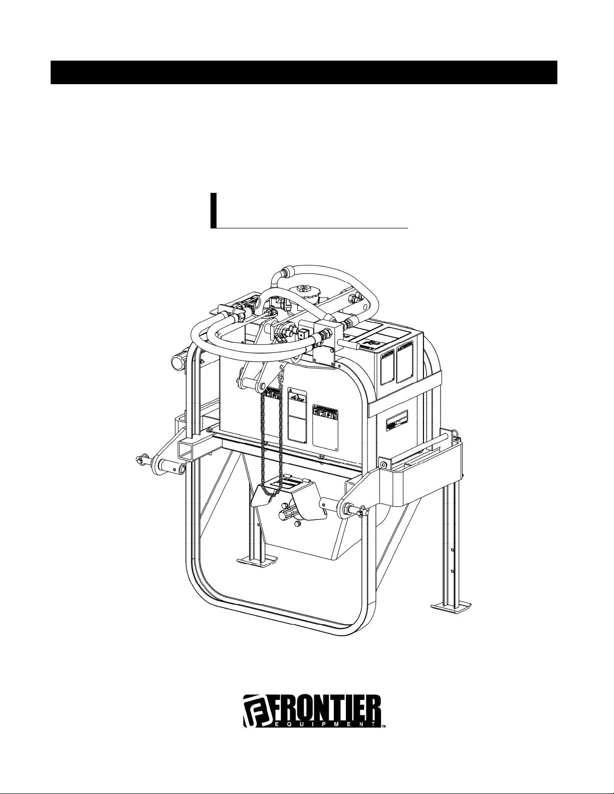
OPERATOR'S MANUAL
HYDRAULIC PUMP
HP2025-HP2134
OM 0399HP-A
05/11


TABLE OF CONTENTS
SPECIFICATIONS ........................................................................................................................................... 3
INTRODUCTION – TO THE PURCHASER ................................................................................................... 4
SAFETY PRECAUTIONS ............................................................................................................................... 5
Before Operation ............................................................................................................................ 5
Notice ............................................................................................................................................. 6
The Hydraulic Pump ...................................................................................................................... 6
Before Operation ............................................................................................................. 6
Hydraulic Pump Operation .............................................................................................. 7
The Tractor .................................................................................................................................... 8
General Information ......................................................................................................... 8
Operating the Tractor ...................................................................................................... 8
During Operation ............................................................................................................. 8
Maintenance .................................................................................................................................. 9
Transport ........................................................................................................................................ 9
Storage ........................................................................................................................................ 9
SAFETY DECALS ................................................................................................................ ................... 10-11
ASSEMBLY ............................................................................................................................................... 12-19
Installation of the Hydraulic Pump ............................................................................................... 12
Hydraulic Oil Fill-Up ..................................................................................................... 12
Installation of the Driveline ........................................................................................... 12
Adjusting the Three Point Hitch ................................................................................... 12
Installation of the Quick Couplers ........................................................................... 13-14
Installation of the Hose Supports ............................................................................ 15-16
Installation of the Wiring Harness ........................................................................... 17-18
Installation of the Hoses .............................................................................................. 19
Installation of the Hydraulic Pump with a Quick Hitch Cat. 1 ....................................... 20
Installation of the Hydraulic Pump with a Quick Hitch Cat. 2 ....................................... 20
Installation of the Hydraulic Pump with a Three Point Hitch Cat. 1 .............................. 21
Installation of the Hydraulic Pump with a Three Point Hitch Cat. 2 .............................. 22
Determining Driveline Length ...................................................................................... 23
Connection the Driveline to the Tractor ....................................................................... 24
Connecting the Hoses and Wiring Harness ................................................................ 25
Installation of the Oil Cooler 5RDF0036 – Option .................................................. 26-27
OM 0399HP-A
1

TABLE OF CONTENTS
OPERATION ................................................................................................................................................ 28-31
Preparation ..................................................................................................................................... 28
Counterweights .............................................................................................................. 28
Operation ........................................................................................................................................ 29
Checking the Oil Temperature ........................................................................................ 29
Checking the Hydraulic Oil Level .................................................................................... 29
Checking Oil Level of the Multiplicator ........................................................................... 29
Removing the Hydraulic Pump ........................................................................................ 30
Reconnecting the Hydraulic pump .................................................................................. 31
MAINTENANCE ................................................................................................................................... 32-40
Lubrication & Periodic Maintenance ................................................................................................ 32
Oil Fill-Up ......................................................................................................................... 33
Oil Change ....................................................................................................................... 33
Replacing the Oil in the Multiplicator ................................................................................ 34
Recommended Hydraulic Oil ........................................................................................... 34
Cleaning the Oil Strainer – without an Oil Cooler ............................................................ 35
Cleaning the Oil Strainer – with an Oil Cooler ................................................................. 36
Instruction for Valve Adjustment ...................................................................................... 37
Troubleshooting .......................................................................................................................... 38-39
Electrical Diagram ............................................................................................................................ 40
PARTS ................................................................................................................................................ 41-53
Introduction .......................................................................................................................................... 41
Hydraulic Pump and Tank .............................................................................................................. 42-43
Miscellaneous ................................................................................................................................. 44-45
Hydraulic and Electrical System ...................................................................................................... 46-47
Hose Supports ................................................................................................................................ 48-49
Hydraulic Block ................................................................................................................................... 50
Hydraulic Pump .................................................................................................................................... 51
Multiplicator .......................................................................................................................................... 52
Oil Cooler 5RDF0036 - Option ............................................................................................................. 53
Driveline ............................................................................................................................................... 54
TORQUE SPECIFICATION TABLES .................................................................................................. 55-57
OM 0399HP-A
2

SPECIFICATIONS
Features and Specifications
Width (with counterweights) 38" (60") 38" (60")
Transport Width
Height
Length 30" 30"
Hydraulic System
Hoses 3/4" 3/4"
Hydraulic Protection
Tank Mounted Strainer
Tank Mounted Return Filter Standard with breather Standard with breather
Hose Protection
Pump Manufacturer
Pump Description
Gearbox Manufacturer
Gearbox Description
Tractor RPM 540 540
32 cc/rev. Model 2.5PB (
HP2025 HP2134
44" 44"
47" (55" with oil cooler) 47" (55" with oil cooler)
16 gpm at 2700 psi 20 gpm at 3000 psi
Relief valve at 2700 psi Relief valve at 3000 psi
Standard Standard
Standard Standard
Salami Salami
Gear pump
Heavy Duty Series)
Breveni Breveni
Model ML52 Model ML52
40 cc/rev. Model 3PB (Heavy Duty Series)
Gear pump
Pump RPM
PTO Manufacturer
PTO Description 40 40
Parking Stand
Hitch Category
Quick Hitch Compatibility ASABE Compatible Cat. 1 & 2
HP Requirements - min-max (hp)
Operating Weight (lbs) with hydraulic oil. 535 535
Shipping Weight (lbs)
Approx. Set-up Time
Capacity of 700 lbs (5 x 70 lbs each side)
Counterweight Support
Rear Attachment Bracket Standard (750 lbs) Standard (750 lbs)
Hose Support for JD3000 & JD4000
series loaders
Quick Couplers – Front & Rear 1/2" Standard 3/4" Standard
Thermal Protection Standard Standard
Pre-drilled holes for oil cooler support Standard Standard
Oil Cooler Option Option
Accepts 42 & 70 lbs John Deere Quick
1836 1836
Comer Comer
Standard Standard
Cat. 1 & 2 Cat. 1 & 2
ASABE Compatible Cat. 1 & 2
25-35 35-56
535 535
1.5 to 2 hrs 1.5 to 2 hrs
Capacity of 700 lbs (5 x 70 lbs each side)
Accepts 42 & 70 lbs John Deere Quick
Tatch Weights
Standard Standard
Tatch Weights
OM 0399HP-A
3

TO THE PURCHASER
INTRODUCTION
All products are designed to give safe,
dependable service if they are operated and
maintained according to instructions. Read and
understand this manual before operation.
This manual has been prepared to assist the
owner and operators in the safe operation and
suitable maintenance of the implements. The
information was applicable to products at the
time of manufacture and does not include
modifications made afterwards.
Read and understand this operator's manual
before attempting to put an implement into
service. Familiarize yourself with the operating
instructions and all the safety recommendations
contained in this manual and those labeled on
the implements and on the tractor. Follow the
safety recommendations and make sure that
those with whom you work follow them.
The Dealer is responsible for warranty registration of the unit you have purchased. To assist your
dealer in handling your needs, please record hereafter the model number and serial number of your
implement and tractor. It is also advisable to supply them to your insurance company. It will be helpful
in the event that an implement or tractor is lost or stolen.
Illustrations
The illustrations may not necessarily reproduce
the full detail and the exact shape of the parts or
depict the actual models, but are intended for
reference only
Direction Reference
Right Hand and Left Hand are determined by
those seen by the operator standing behind the
equipment.
MODEL :
SERIAL NUMBER :
DATE OF PURCHASE :
OM 0399HP-A
4

SAFETY PRECAUTIONS
SAFETY FIRST
This symbol, the industry's "Safety Alert Symbol", is used throughout this manual and on
labels on the machine itself to warn of the possibility of personal injury. Read these
instructions carefully. It is essential that you read the instructions and safety regulations
before you attempt to assemble or use this unit.
DANGER : Indicates an imminently hazardous situation which, if not avoided, will
result in death or serious injury.
WARNING : Indicates a potentially hazardous situation which, if not avoided, could
result in death or serious injury.
CAUTION : Indicates a potentially hazardous situation which, if not avoided, may
result in minor or moderate injury.
IMPORTANT : Indicates that equipment or property damage could result if instructions
are not followed.
NOTE : Gives helpful information.
All products are designed to give safe, dependable service if they are operated and maintained
according to instructions. Read and understand this manual before operation
responsibility to be certain anyone operating this product reads this manual, and all other applicable
manuals, to become familiar with this equipment and all safety precautions. Failure to do so could result
in serious personal injury or equipment damage. If you have any questions, consult your dealer.
. It is the owner's
BEFORE OPERATION
Children and Bystanders
Tragic accidents can occur if the operator is not
alert to the presence of children. Children are
generally attracted to machines and the work
being done. Never assume children will remain
where you last saw them.
1. Keep children out of the operating area and
under the watchful eye of another
responsible adult.
2. Be alert and turn machine off if children
enter the work area.
3. Before and when backing, look behind and
look for small children.
OM 0399HP-A
4. Never carry children while operating the
machine. They may fall off and be seriously
injured or interfere with safe operation of the
machine.
5. Never allow children to play on the machine
or attachment even when turned off.
6. Never allow children to operate the machine
even under adult supervision.
7. Use extra care when approaching blind
corners, shrubs, trees, or other obstructions
that might hide children from sight.
5

SAFETY PRECAUTIONS - continued
NOTICE
A safe operator is the best insurance against accidents. All operators, no matter how experienced they
may be, should read this Operator's Manual and all other related manuals before attempting to operate
an implement. Please read the following section and pay particular attention to all safety recommendations contained in this manual and those labeled on the implements and on the tractor.
THE HYDRAULIC PUMP
Before Operation
1. Read an d understand this operator's manual
and tractor operator's manual. Know how to
operate all controls and how to stop the unit
and disengage the controls quickly.
2. Never wear loose, torn, or bulky clothing
around the tractor and implement. It may
catch on moving parts or controls, leadi ng to
the risk of accident.
3. Before the snow season, thoroughly inspect
the area where the equipment is to be used
and remove all doormats, sl eds, boards and
other foreign objects.
4. Disen gage clutch and shi ft into neutral befo re
starting the engine.
5. Do not operate equipment in wintertime
without wearing adequate winter garments.
6. Never attempt to make any adjustments while
engine is running. Read this man ual carefully
to acquaint yourself with the equipment as
well as the tractor operator's manual.
Working with unfamiliar equipment can lead
to accidents. Be thoroughly familiar with the
controls and proper use of the equipment.
Know how to stop the unit and dise ngage the
controls quickly.
9. Replace all missing, illegible, or damaged
safety and warning decals. See list of decals
in the operator's manual.
10. Do not modify or alter this equipment or any
of its components or any equipment function
without first consulting you r de aler.
11. Keep safety decals clean of dirt and grime.
7. Keep all shields in place and properly tighten
all mounting hardware.
8. Periodically, inspect all moving parts for wear
and replace with authorized service parts if
an excessive amount of wear is present.
OM 0399HP-A
6

SAFETY PRECAUTIONS - continued
Hydraulic Pump Operation
1. Before leaving the tractor unattended, take
all possible precautions. Disengage the
PTO, stop the engine and remove the
ignition key. Lower the implement to the
ground.
2. Before starting the pump, make sure there's
sufficient hydraulic oil and that hoses are
properly connected.
3. Be sure the clutch switch/lever is in OFF
position before starting engine.
4. Exercise extreme caution when operating
on or crossing a gravel drive, walks, or
roads. Stay alert for hidden hazards or
traffic.
5. Do not carry passengers.
6. If the pump starts to vibrate abnormally,
stop the engine immediately and check for
cause. Excessive vibration is generally a
sign of trouble.
7. Do not run the engine indoors except when
starting engine and transporting attachment
in or out of building. Carbon monoxide gas
is colorless, odorless and deadly.
13. Prolonged exposure to loud noise can
cause impairment or loss of hearing. Wear a
suitable hearing protective device such as
earmuffs or earplugs to protect against
objectionable or uncomfortable noises.
14. Always keep the "SMV" sign (Slow Moving
Vehicle) visible and clean.
15. Make sure the protective nylon sheat is
properly installed on the hoses since they
contain fluid under pressure and at high
heat that can cause injury.
8. Exercise extreme caution when changing
direction on slopes. Do not attempt to
operate on steep slopes.
9. Never operate pump without guards, and
other safety protective devices in place.
10. Never operate machine at high transport
speeds on a slippery surface.
11. Use extra caution when backing up.
12. Disengage power to the PTO when
transporting or when not in use.
OM 0399HP-A
7

SAFETY PRECAUTIONS - continued
THE TRACTOR
General Information
1. Read the operator's manual carefully before
using tractor. Lack of operating knowledge
can lead to accidents.
Operating the Tractor
1. Never run the tractor engine in a closed
building without adequate ventilation, as the
exhaust fumes are very dangerous.
2. Never allow an open flame near the fuel
tank or battery.
3. Make sure the shield is installed when using
PTO-driven equipment and always replace
the shield if damaged.
4. Always bring the tractor to a complete stop,
shut off the engine, lower the implement to
the ground and remove the ignition key
before leaving the tractor.
5. Never park the tractor on a steep slope.
6. Do not attempt to operate on steep slopes.
7. Use of tire chains for better traction and
stability is recommended.
8. Always drive the tractor at speeds
compatible with safety, especially when
operating over rough ground, crossing
ditches, or when turning.
9. Handle fuel with care, as it is highly
flammable.
10. Use approved fuel container.
11. Never add fuel to a running engine or a hot
engine.
12. Fill fuel tank outdoors with extreme care.
Never fill fuel tank indoors. Replace fuel cap
securely and wipe up spilled fuel.
13. Never allow anyone to operate the front
mount implement until they are thoroughly
familiar with basic tractor and implement
operation.
2. Do not allow anyone but the operator to ride
on the tractor. There is no safe place for
extra riders
14. A minimum 20% of tractor and equipment
weight must be on the tractor front wheels
when attachments are in transport position.
Without this weight, tractor could tip over,
causing personal injury or death. The weight
may be attained with a loader, front wheel
weights, ballast in tires, front tractor weights
and/or on the power pack. Weigh the tractor
and equipment. Do not estimate. Please
refer to tractor manual for proper ballasting
information.
15. Always make sure all hydraulic pump
components are properly installed and
securely fastened BEFORE operation.
During Operation
1. Do not allow anyone to ride on the
tractor/implement at any time. There is no
safe place for passengers on this
equipment. The operator MUST sit in the
tractor seat.
2. Eye and hearing protection is recommended
when operating the hydraulic pump.
3. Operate only during daylight hours, or when
the area is well lit with bright artificial light.
4. Disengage the PTO (turn to “OFF”), place
the transmission in neutral, set the parking
brake, shut off the engine and remove the
key, and make sure rotating components
have stopped BEFORE leaving the
operator’s seat.
5. Inspect the hydraulic pump after striking any
foreign object to assure that all implement
parts are safe and secure and not damaged.
OM 0399HP-A
8

SAFETY PRECAUTIONS - continued
MAINTENANCE
1. Park the tractor/hydraulic pump on level
ground, set the parking brake, disengage
the PTO, shut off the engine, remove the
key, and lower the implement to the ground
BEFORE making any hydraulic pump
adjustments.
2. Keep the tractor/hydraulic pump clean.
Snow and ice build-up can lead to
malfunction or personal injury from thawing
and refreezing in garage.
3. Always wear eye protection when cleaning
or servicing the hydraulic pump.
4. Do not work under any part of the tractor or
hydraulic pump, unless it is securely
supported by safety stands.
5. Make sure all shields and guards are
securely in place following all service,
cleaning, or repair work.
6. Do not modify or alter this equipment or
any of its components or operating
functions. If you have questions concerning
modifications, consult with your dealer.
7. Even when stopped, the hydraulic pump
(hoses, oil tank, and pump) can contain
fluids under pressure and at high heat. Be
very careful when performing maintenance
on this equipment.
TRANSPORTATION
1. If the tractor/hydraulic pump is to be driven
on public roads, it must be equipped with
an SMV (Slow Moving Vehicle) sign.
Check local traffic codes that may apply to
unit usage on public roads and highways in
your area.
2. Be alert for all other traffic when driving the
tractor/ hydraulic pump on public roads or
highways.
3. During transport, the hydraulic pump must
be in the raised position.
STOR AGE
1. Before storing the hydraulic pump, certain
precautions should be taken to protect it
from deterioration.
2. Clean the hydraulic pump thoroughly.
3. Make all the necessary repairs.
4. Replace all Safety Signs that are damaged,
lost, or otherwise become illegible. If a part
to be replaced has a sign on it, obtain a
new safety sign from your dealer and install
it in the same place as on the removed
part.
5. Repaint all parts from which paint has worn
or peeled.
.
OM 0399HP-A
6. Lubricate the hydraulic pump as instructed
under "Lubrication" section.
7. When the hydraulic pump is dry, oil all
moving parts. Apply oil liberally to all
surfaces to protect against rust.
8. Place the dust caps on the hoses. Store
the hydraulic hoses in the hose support on
top of the oil tank and secure in place with
the connector support and the hairpins.
9. Attach the driveline to the pump with the
chain provided with the pump.
10. Store in a dry place
9
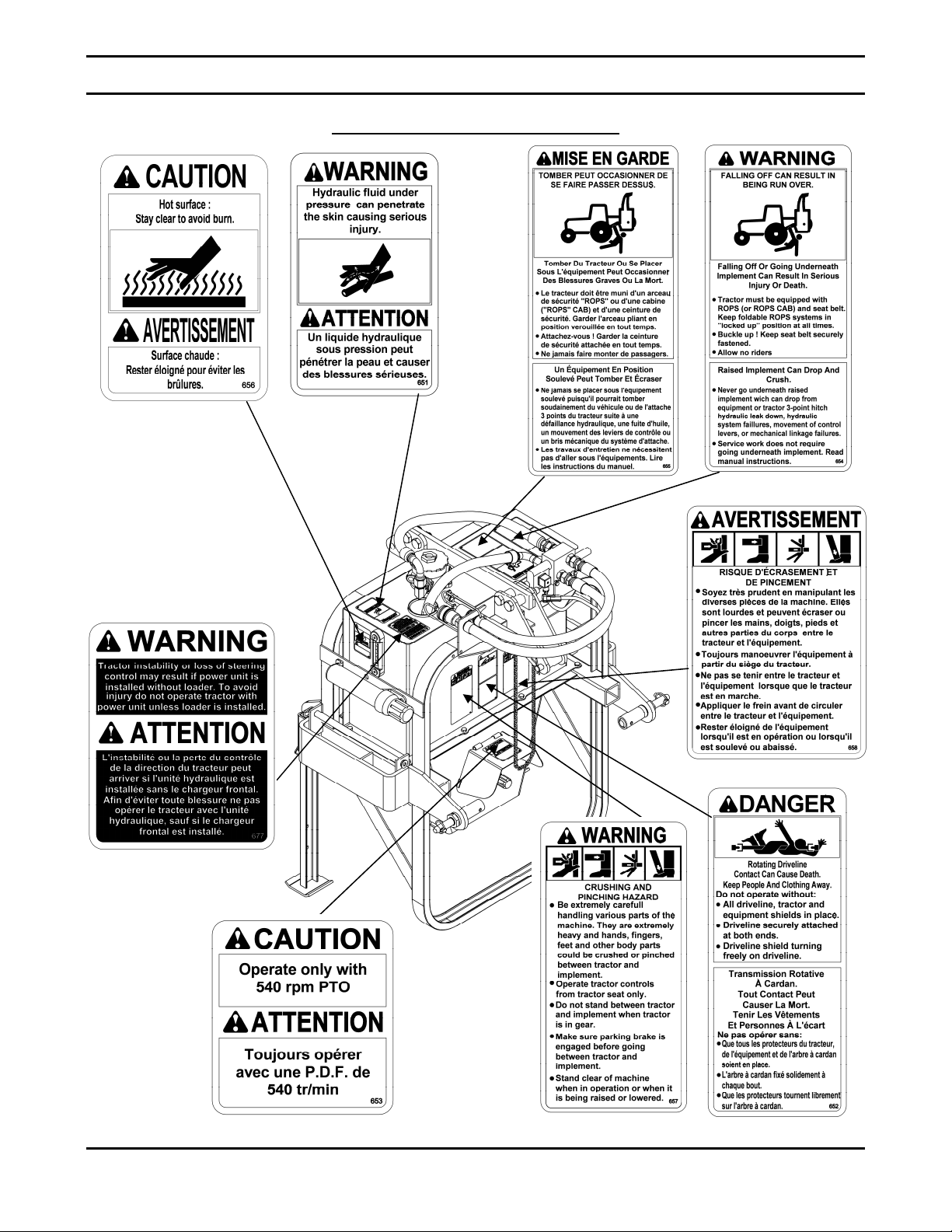
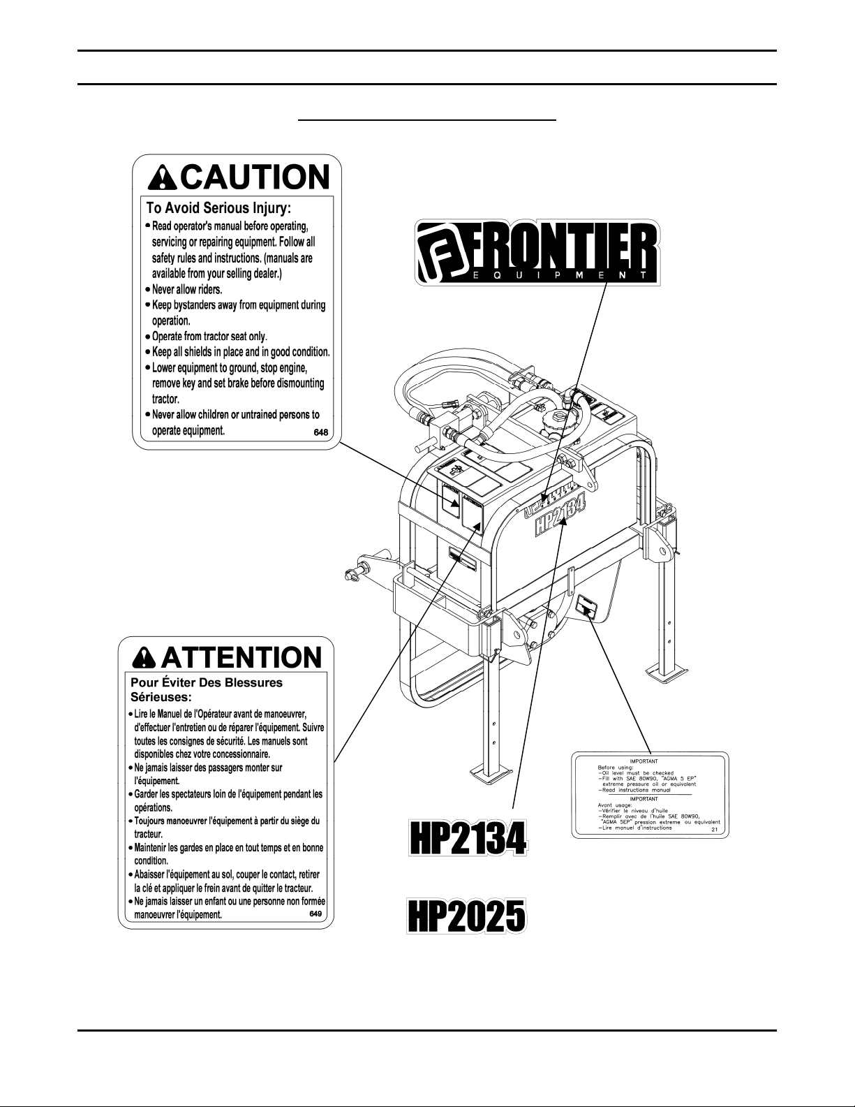
DECALS
Replace immediately if damaged
5RD2500796
5RD2500791
5RD2500795
5RD2500794
5RD2500829
OM 0399HP-A
5RD2500793
10
5RD2500797
5RD2500798
5RD2500792
DECALS
Replace immediately if damaged
5RD2500616
5RD2500785
OM 0399HP-A
5RD2500786
5RD2500822
5RD2500821
11
5RD655834
5RD655834
ASSEMBLY
INSTALLATION OF THE THREE POINT HYDRAULIC PUMP
The hydraulic pump is assembled at the factory; however it needs to be installed and connected. Use
the present manual and lay out all parts. Separate bolts and nuts into various sizes. After installation,
torque all the bolts and the hydraulic fittings according to the "Torque Specification Tables" at the end
of the manual.
Hydraulic Oil Fill-Up
The hydraulic pump is delivered
without hydraulic oil. Fill up the oil
tank according to the instructions in
the "Maintenance" section.
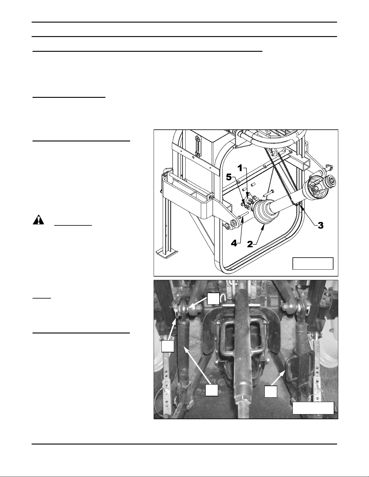
Installation of the Driveline
Figure 1: Remove the two M12 x
1.25 x 70 bolts (item 4) and the
nylon insert locknuts (item 5).
Connect the driveline (item 2) to the
pump's driveshaft (item 1). Attach
with the two M12 x 1.25 x 70 bolts
(item 4) and the nylon insert locknuts
(item 5). Maintain in place with the
chain (item 3).
WARNING: To avoid
serious personal injuries: If the
collar is not locked to the shaft at
tractor end and the bolts not well
tighten to the pump shaft (a
"click" must be heard), the
driveline can fly loose with great
force capable of causing serious
injury or death.
Figure 1
NOTE
installation of the pump on the
tractor, figures 20 and up do not
show the driveline.
: To better illustrate the
Adjusting the 3 Point Hitch
Figure 2: Adjust the three point hitch
at maximum height by screwing the
right arm adjustable link to its
maximum using the handle (item 1).
For the left arm, remove the linchpin
(item 2) and remove the adjustable
link (item 3) from the upper
anchoring point (item 4). Screw the
adjustable link (item 3) to the
maximum and reinstall. Make sure
the two lower arms are at the same
height.
OM 0399HP-A
4
2
3
12
1
Figure 2
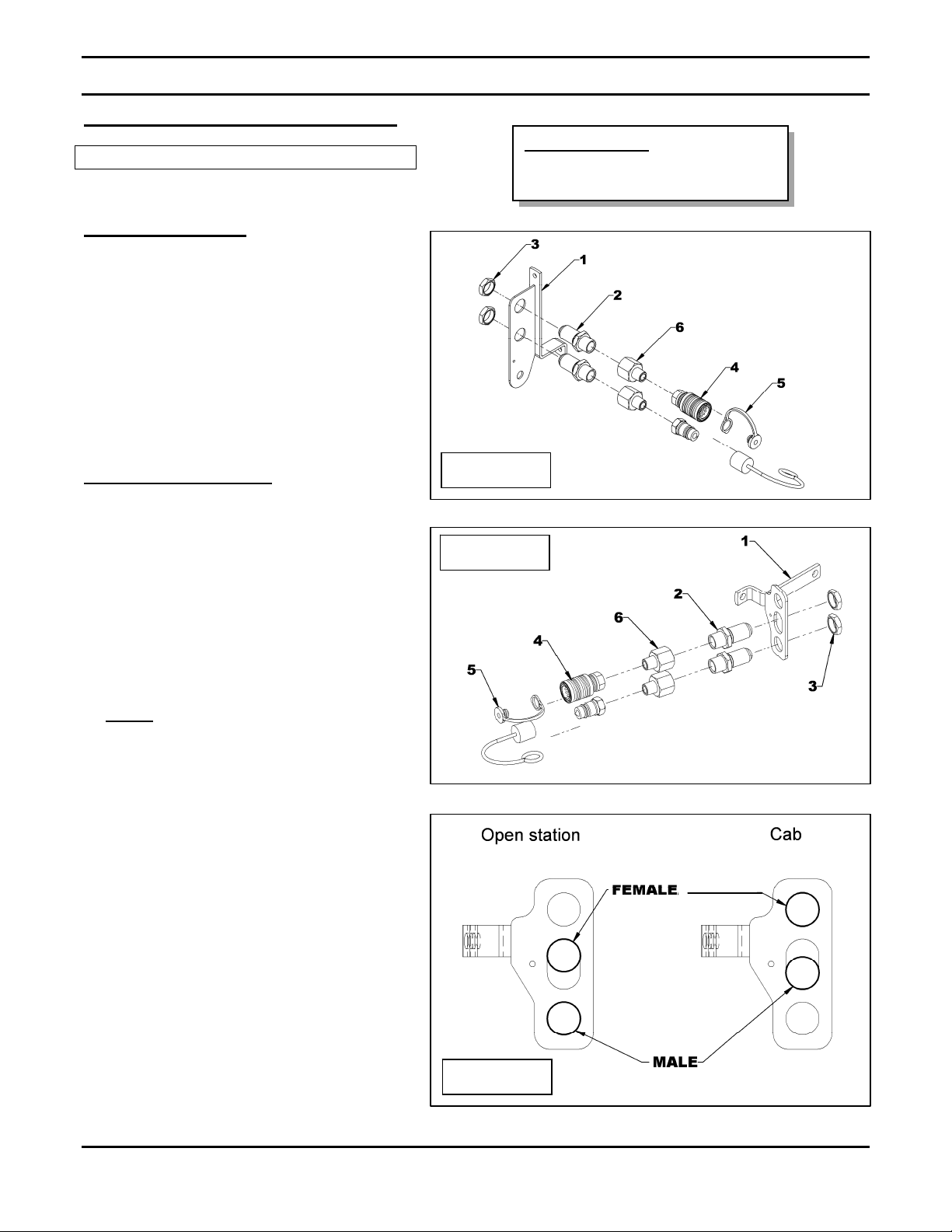
Installation of the Quick Couplers
3X20 TRACTOR
ASSEMBLY
Tractor Legend:
3X20 = 3320, 3520, 3720
4X20 = 4120, 4320, 4520, 4720
Front support - fig.3
1. Install two 1 1/16"JIC x 3/4"NPT
bulkhead adaptors (item 2) on the
middle hose support (item 1) with
1 1/16" bulkhead nuts (item 3).
2. Install two 3/4"NPT x 1/2"NPT male
adaptors (item 6) followed by a 1/2"
male quick coupler, a 1/2" female quick
coupler (item 4) with their respective
dust plug and dust cap (item 5) in the
order illustrated.
Rear support - fig.4 & 5
1. Install two 1 1/16"JIC x 3/4"NPT
bulkhead adaptors (item 2) on the rear
hose support (item 1) with 1 1/16"
bulkhead nuts (item 3).
2. Install two 3/4"NPT x 1/2"NPT male
adaptors (item 6) followed by a 1/2"
male quick coupler, a 1/2" female quick
coupler (item 4) with their respective
dust plug and dust cap (item 5) in the
order illustrated.
NOTE
position of the quick couplers.
: Refer to figure 5 for the
Figure 3
Figure 4
OM 0399HP-A
Figure 5
13
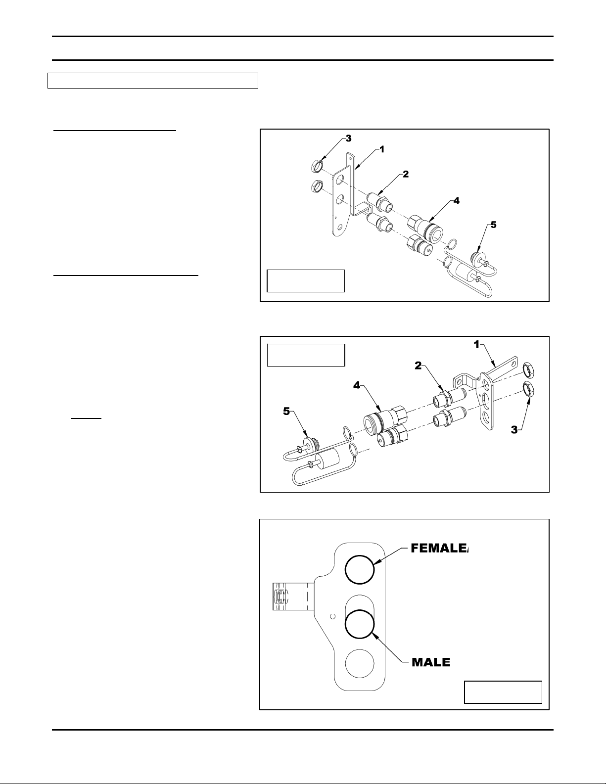
ASSEMBLY
4X20 TRACTOR
Front support – figure 6
1. Install two 1 1/16"JIC x 3/4"NPT
bulkhead adaptors (item 2) on the
middle hose support (item 1) with
1 1/16" bulkhead nuts (item 3).
2. With thread sealant, install a 3/4"
male quick coupler and a 3/4" female
quick coupler (item 4) with their
respective dust plug and dust cap
(item 5).
Rear support – figures 7 & 8
1. Install two 1 1/16"JIC x 3/4"NPT
bulkhead adaptors (item 2) on the
rear hose support (item 1) with
1 1/16" bulkhead nuts (item 3).
2. With thread sealant, install a 3/4"
male quick coupler, a 3/4" female
quick coupler (item 4) with their
respective dust plug and dust cap
(item 5) in the order illustrated.
Figure 6
Figure 7
NOTE
position of the quick couplers.
: Refer to figure 8 for the
Figure 8
OM 0399HP-A
14
ASSEMBLY
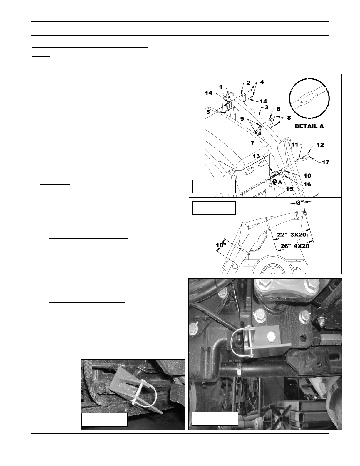
Installation of the Hose Supports
NOTE: Refer to the parts section on page 50 to identify the hose supports and to figure 9a for their
exact location on the loader arm.
1. Figure 9: Attach the rear hose support (item 1)
and the fastening bracket (item 2) to the left front
loader arm (item 3) with two 5/16" NC x 1 1/4" lg
bolts, 5/16" flat washers and 5/16" NC nylon
insert nuts (items 4-14-5).
2. Figure 9: Attach the mid dle hose support (item 7)
and its fastening bracket (item 6) with two 5/16"
NC x 1 1/4" lg. bolts and two 5/16" NC nylon
insert nuts (items 8-9).
3. Figures 9: Attach the lower part of the front hose
support (item 10) and its fastening plate (item 11)
with one 5/16"NC x 3 1/2" lg bolts and one 5/16"
NC nylon insert nuts (items 12-13) and the upper
part with 1/4"NC x 6" flattened bolt, a bushing and
a 1/4"NC nut (items 15-16-17).
CAUTION
particularly with the front support (items 10-
11).
IMPORTANT
portion of the 1/4"NC bolt faces the loader
cylinder and is in a position that ensures the
cylinder doesn't interfere with the bolt.
4. A- For 3X20 tractors - fig.10a
Attach the hose support in the same location as
the tractor hose support located under the left
tractor step plate using the existing tractor bolt.
Install the round wire lock pin in the support as
shown.
On some tractor, it may be necessary to position
the support with an angle as shown on fig.10a.
B- For 4X20 tractors - fig.10
Attach the hose support (item 1) on the front
loader support plate located under the step plate
(item 2) with a 5/8" NC x 2" lg. bolt (item 3) and a
5/8" NC nylon insert nut (not illustrated). Install
the round wire lock pin (item 4) in the holes of the
support.
: Do not cover the loader arm decals
- Detail A: Make sure the flattened
:
:
Figure 9
Figure 9a
OM 0399HP-A
Figure 10a
Figure 10
15
ASSEMBLY
5. Run the hydraulic hoses from the rear of
the tractor to the front without inserting
them in the hose supports. The straight
hose fittings go on the front of the tractor.
6. Figures 11: Connect the hoses (item 2)
to the rear bulkhead adaptors (item 1).
Figure 11
7. A- Without cab
- Remove the bolt and the flat washer
that holds the left fender to the
tractor frame.
- Insert a M10 x 1.5 x 60mm bolt (not
illustrated) in the hole of the bent
section of the fastening bracket
(item 1).
- Insert the fastening bracket, from the
front to the rear, around the tractor
post (item 2) and secure with a M10
x 1.5 x 60mm bolt for the 4X20
M10 x 1.5 x 40mm bolt for the 3X20
(item 3), and the tractor flat washer
previously removed, located
between the bracket and the tractor
aisle. DO NOT use this flat washer
for the 3X20 tractor.
- After installing the hoses on the bulk
head adaptors, attach the rear hose
support (item 4) around the tractor
post inserting the front part first and
secure in place with a 3/8" flat
washer (not illustrated) and a 10mm
nylon insert nut (not illustrated).
: Figure 12:
or a
Figure 12
5
4
- Attach the rear section with a 10mm
nylon insert nut (item 5).
B- With cab
Attach the rear hose support (item 1)
and it's fastening bracket (item 2) to
the tractor post (item 3) at about 9"
from the axle's upper plate for the
3X20 series and at 6 3/4" for the 4X20
series with two M10 x 1.5 x 60mm
bolt, 3/8" flat washers and two 10mm
nylon insert nut (items 4-5-6).
OM 0399HP-A
: Figure 12A:
16
3X20: 9"
4X20: 6 ¾"
3
6
2
1
Figure 12A

ASSEMBLY
Installation of the Wiring Harness
1. Figure 13: Connect the red wire
terminal (item 1) of the harness with
the fuse holder, to the battery's
positive terminal (item 2) and the
black wire terminal (item 3) to the
battery's negative terminal (item 4).
Attach the harness to the tractor
wiring close to the relay with a tie
wrap (item 5).
4
5
2. Figures 14-15: Insert the wiring
harness (item 1) in the rubber boot
(item 2). On some tractor models it
may be necessary to remove the hose
clamp (item 3) to be able to insert the
harness. Reinstall the clamp once the
harness is installed.
3. Figure 15: Run the wiring harness
(item 1) along the front of the tractor
frame and attach to the tractor wiring
or hoses (item 4) with tie wraps. Run
the harness close to the hose support
located under the step plate (not
illustrated).
Figure 15
Figure 13
Figure 14
1
2 3
1
2
3
OM 0399HP-A
2 1
17
1
4

4. Figure 16: Find the tractor's drive
wheel activation switch on the
transmission near the left rear axle
(item 1), accessible from the bottom
of the left footstep. Disconnect the 2
cavity connector. Connect the
identical harness connector to the
activation switch and the tractor's 2
cavity connector to the wiring
harness.
5. Figure 17: Run the harness all the
way to the back making sure not to
interfere with the movement of the
tractor levers and keeping as far
away as possible from the wheel.
Bring the harness to the rear hose
support (item 1) and tie the harness
close to it so the connector (item 2)
is at the same level as the quick
couplers previously installed. Tie the
harness to all the critical areas on
the tractor.
ASSEMBLY
1
Figure 16
NOTE:
harness in a place far from the wheels
and the tractor control levers in
movement.
Attach the surplus of the
2
1
OM 0399HP-A
Figure 17
18

ASSEMBLY
Installation of the Hydraulic Hoses
1. Figure 18: Connect the hoses to the
front bulkhead adaptors (item 1). Hoses
should not be inserted in the supports to
make it easier to connect the hoses in
the front. Tighten the lower hose first
(item 2).
Figure 18
2
1
2. Figure 19a: Insert the hoses (item 1) in the
rear hose support (item 2) of the left loader
arm.
3. Figures 19b-19c: Run the hoses (item 1)
under the tractor as shown on figure 19b
then insert the hoses in the hose support
located under the step plate (item 2) then
lock in place with a round wire lock pin
(item 3).
Figure 19a
1
2
OM 0399HP-A
Figure 19b
1
19
Figure 19c
2
3

ASSEMBLY
Installation of the Hydraulic Pump
with a Quick Hitch Cat. 1
Figure 20: Place the hydraulic pump
(item 1) on flat hard ground. Unlock the
lower locks of the quick hitch (item 2).
Back up the tractor slowly aligning the
three quick hitch hooks (item 4) with the
three bushings (item 3) of the hydraulic
pump and lock the quick hitch lower locks.
Installation of the Hydraulic Pump
with a Quick Hitch Cat. 2
1. Figure 21: Remove the linchpins
(item 1), lockwashers (item 3), nuts
(item 2) and pins (item 4). Use a round
stalk to block the cat.1 and 2 pin during
the loosening and the tightening of the
nut.
2. Figure 22: Install the pins (item 1) in the
position illustrated and reinstall the
lockwashers (item 3), nuts (item 2), and
linchpins (item 4).
Figure 20
3. Figure 23: Place the hydraulic pump
(item 1) on flat hard ground. Unlock the
lower locks of the quick hitch (item 2).
Back up the tractor slowly aligning the
three quick hitch hooks (item 4) with the
three bushings (item 3) of the hydraulic
pump and lock the quick hitch lower
locks.
Figure 21
Figure 22
OM 0399HP-A
Figure 23
20

ASSEMBLY
Installation of the Hydraulic Pump
with a Three Point Hitch Cat. 1
1. Figure 24: Remove the linchpins (item 1),
nuts (item 2), lockwashers (item 3) and pins
(item 4). Remove the hairpin (item 5), pin
(item 6) and bushing (item 7). The lower
quick hitch bushings (item 8) can remain in
place.
2. Figure 25: Insert the pins (item 1) in the
position illustrated. Reinstall the
lockwashers (item 3), the nuts (item 2) and
the linchpins (item 4).
3. Figure 26 I nsert the two pins (item 1) in the
lower links (item 2) and lock in place with
linchpins (item 3). Attach the upper link
(item 5) with the 4" lg. pin (item 4) and lock in
place with the hairpin (item 6).
Figure 24
Figure 25
OM 0399HP-A
Figure 26
21

ASSEMBLY
Installation of the Hydraulic Pump
with a Three Point Hitch Cat.2
1. Figure 27: Remove the linchpins (item 1),
nuts (item 2), lockwashers (item 3) and pins
(item 4). Remove the hairpin (item 5), pin
(item 6) and bushing (item 7). Remove the
spring pins (item 8) and the bushings
(item 9).
2. Figure 28: Insert the pins (item 1) in the
position illustrated. Reinstall the nuts
(item 2), lockwashers (item 3) and the
linchpins (item 4).
3. Figure 29: Insert the two pins (item 1) in the
lower links (item 2) and lock in place with
linchpins (item 3). Attach the upper link
(item 7) by inserting a cat.1 & cat.2 bushing
(item 5, sold separately #5RD4600056), the
4" pin (item 4) and a hairpin (item 6).
Figure 27
Figure 28
OM 0399HP-A
Figure 29
22

ASSEMBLY
A
Determining Driveline Length
IMPORTANT: To not damage the equipment, it
is essential that the driveline is not too long. At
working position, the two half drivelines must
intersect each other sufficiently to insure
maximum efficiency but there must not be any
interference.
1. To determine the "L" length for your tractor
model first find the "X" factor by measuring
the distance between the end of the
tractor's drive shaft and the end of the
hydraulic pump's driven shaft when the
hydraulic pump is in raised position as
shown on Figure 30.
2. Deduct 4" from the "X" length measured
from the tractor to obtain the "L" length
from center to center of the journal crosses:
L = X – 4"
3. Hold the two half-shaft side by side and
locate the "L" length between the two
center-to-center half-shaft universal joints.
Mark off the zone to be cut on both halves
opposite each half-shaft guard as shown on
Figure 31.
Figure 30
Figure 31
4. Cut off inner and outer guard tubes as well
as the inner and outer telescopic sections.
5. Cut the guard a second time leaving the
same distance between the end of the guard
and the end of the shaft as existed before.
To obtain the proper distance "A" shown on
Figure 32, cut the guard according to the
following table:
DISTANCE A
Male Driveline Female Driveline
1 3/4" 1 1/4"
6. File down tubes and remove chips.
7. Apply grease to inside of outer telescopic
section.
WARNING: To avoid serious
personal injuries that may cause death,
work with fully guarded shafts only.
Figure 32
OM 0399HP-A
23

ASSEMBLY
Connecting the Driveline to the Tractor
Figures 33a-33b: Release the springhook
(item 1) to remove the chain (item 2) from
around the driveline (item 3) and reattach the
springhook in its original position (item 1).
Connect the driveline (item 4) to the tractor
driveshaft (item 5). Attach each driveline
chains (item 6) to the tractor lower hitches
(item 7) to prevent the guards from spinning.
Figure 33a
Figure 33b
OM 0399HP-A
24

ASSEMBLY
Connecting the Hydraulic Hoses and Wiring Harness
1. Figure 34: Remove the hoses
(item 2) from the hose support
(item 1) on the hydraulic pump.
2. Figure 35: Connect the hoses to the
rear tractor ports (item 1).
3. Figure 35: Connect the wiring
harness to the rear tractor connector
(item 2).
Figure 34
OM 0399HP-A
2
1
Figure 35
25

ASSEMBLY
Installation of the Oil Cooler 5RDF0036 - Option
1. Figure 36: Unscrew the 1 1/16" JIC elbow
(item 1) from the in-tank filter. Remove the
3/4"NC x 2" lg bolt (item 2) and the stover nut
(item 3). Remove the stover nut (item 4) from
the 3/4"NC x 4 1/2" lg bolt but do not remove
the bolt.
2. Figure 36a: Unscrew the straight 1-1/16"JIC
adapter (item 1) and rotate the hose of 90°
up to bring up the 90° 1-1/16"JIC elbow
adapter (item 2). Tighten the straight 11/16"JIC adapter, to rotate the hose, at 65-75
ft-lb (93-101 N-M).
3. Figure 37: Install the oil cooler support
(item 1) with a 3/4" NC x 2" lg bolt (item 2)
and the 3/4" stover nut (item 3) removed
previously. Reinstall the 3/4" NC stover nut
(item 4) previously removed on the 3/4" NC x
4 1/2" bolt.
4. Figure 38: Install the support plates (item 1)
with six 5/16" NC x 1" bolts (item 2), eight
5/16" flat washers (item 3) and six 5/16" NC
nylon insert nuts (item 4) making sure to
place a flat washer between the support
plates and the "U" section of the frame.
Figure 36
Figure 36a
Figure 37 Figure 38
OM 0399HP-A
26

ASSEMBLY
5. Figure 39: Install the rubber bushings (items 1-2)
on the support then attach the oil cooler (item 3)
with four 5/16" NC x 2 1/4" bolts (item 4), 5/16"
flat washers (item 5), the flat washers supplied
with the rubber bushings (item 6) and 5/16" NC
nylon insert nuts (item 7). IMPORTANT
the oil cooler so the by-pass valve (item 8) faces
the rear as illustrated.
6. Figure 40: Install the 1 5/8" ORB – 1 1/16" JIC
elbows (item 1) on the oil cooler's inlet and outlet
in the positions illustrated. Connect the straight
end of the outlet hose (item 2) to the oil cooler
elbow and the bent end to the filter. Connect the
inlet hose (item 3) previously disconnected from
the filter to the other elbow making sure it passes
outside the support plate (item 4).
7. Figure 41: Connect the oil cooler fan harness
(item 1) to the available connector on the
hydraulic pump's wiring harness (item 2).
: Position
Figure 39
Figure 40
Figure 41
1
2
OM 0399HP-A
27

OPERATION
PREPARATION
1. Figure 42: Raise the three point hitch at
maximum making sure the adjustable arms
are at maximum height. (see section
"Adjusting the Three Point Hitch". When the
pump is fully raised, the driveline must be at
an angle nearest to 5º with the ground. If
not, adjust the three point hitch until the
driveline has the correct angle to prevent
premature wear of the driveline. The angle
of the pump's input shaft is also very
important; it must be as parallel as possible
with the output shaft of the tractor.
2. Raise the parking stands and lock in place
with the wire lock pins.
IMPORTANT
adjusted correctly and the parking stands are
not raised, ground clearance and the pump's
angle will be affected making it more difficult to
travel on uneven terrain.
3. Before starting the tractor, make sure the oil
level of the oil tank and multiplicator is
correct (see sections "Checking the
Hydraulic Oil Level" and "Checking Oil Level
of the Multiplicator".
4. Attach a suitable implement to the tractor
front loader making sure the implement is
compatible with the hydraulic pump (see
specifications for each).
5. For equipment other than the snowblower,
working in warm region, use the 5RDF0036
oil cooler.
IMPORTANT:
cooler, it is essential to disconnect the
fan of the oil cooler when the
temperature is under 0°C.
6. Figure 43: The new HP2025 and HP2134
pumps are equipped with a safety system to
prevent the hydraulic oil from overheating.
When the hydraulic block is not power
supplied, the oil is in recirculation mode
meaning that the equipment will not
function. To power the block, the ignition
key must be in the "ON" (1) or "START" (2)
position. If the system remains in the
recirculation mode, refer to the
"Troubleshooting" section at page 39.
7. Engage the tractor PTO. Run the
equipment 2 to 3 minutes to make the
hydraulic oil circulate throughout the
system. Disengage the PTO and check the
oil level in the oil tank once more. Add oil if
needed.
: If the three point hitch is not
To not damage the oil
Figure 42
Figure 43
1
Without Cab | With Cab
2
Counterweights
IMPORTANT: Make sure the tractor has
counterweights as recommended by the
dealer. Weights provide the necessary
balance to improve stability, traction and
steering. The recommended Quick Tatch
weights are available at your local John
Deere dealer.
Figure 44: Remove the counterweight rods
(item 1) and the hairpins (item 2). Hang the
counterweights (item 3) on each side of the
hydraulic pump. Reinstall the rods (item 1) and
the hairpins (item 2).
Figure 44
OM 0399HP-A
28

OPERATION
Checking the Oil Temperature
Figure 45: Check the oil temperature indicated
on the thermometer (item 1) of the hydraulic
pump (item 2).
IMPORTANT: The oil temperature must
never exceed 149ºF (65ºC). If the
temperature is above that, disengage the
hydraulic pump to allow the oil to return
to a temperature below 149ºF (65ºC). A
temperature higher than 149ºF (65ºC)
could cause damage to the hydraulic
components.
Checking the Hydraulic Oil Level
Figure 46: The oil level must be between the
red line and blue line of the level indicator
(item 1). If the level is close to the red line, add
some oil to bring it back to the blue line. Make
sure the oil level never goes below the red line
on the indicator (item1).
Figure 45
IMPORTANT: Make sure the oil level
never goes below the red line on the
indicator while in operation or it could
cause damage to the hydraulic pump.
Checking Oil Level of the Multiplicator
Figure 46: To check the oil level, simply look
through the oil level plug (item 1) located on the
right hand side of the multiplicator. If the gauge
glass is yellowish, the oil level is good. If it's
white, add someSAE80W90 oil.
Figure 46
OM 0399HP-A
29

Removing the Hydraulic Pump
1. Figure 47: Remove the wire lock pins
(item 2), lower the parking stands
(item 1) and lock in place with the
wire lock pins (item 2). Lower the
hydraulic pump to the ground.
OPERATION
IMPORTANT
lowered on level ground since the
hydraulic pump has a high center
of gravity and could tip over if it's
set on uneven ground.
2. Figure 48: Disconnect the hoses
(item 1) and the harness (item 2) if
they are connected to the tractor and
install the appropriate dust
caps/plugs on each hose connector
and tractor outlets.
3. Figure 49: Place the hoses and
wiring harness on top of the hydraulic
pump. Insert the hoses (item 2) in the
hose support (item 1).
4. Figure 47: Disconnect the driveline
(item 3) from the tractor's driveshaft
(item 4).
5. Figure 42: Attach the driveline
(item 3) to the hydraulic pump with
the chain (item 4).
: The pump must be
Figure 47
2
OM 0399HP-A
Figure 49
Figure 48
30
1

OPERATION
6. A - For Quick Hitch Installation
Figure 50: Unlock the lower locks of the
quick hitch. Lower the three point hitch to
release the hooks (item 1) from the pump's
attaching points (item 2) and move the
tractor forward slowly.
B - For Three Point Hitch Installation
Figure 51: Remove the hairpin (item 6) and
the pin (item 4) to release the upper link
(item 5) and place it on its support (not
illustrated). Remove the linchpins (item 3)
to release the lower links (item 2) from the
pins (item 1) and move the tractor forward
slowly.
:
:
Reconnecting the Hydraulic Pump
1. Adjust the three point hitch according to the
instructions on page 12.
Figure 50
2. Install the hydraulic pump on the tractor
according to the instructions starting on
page 20:
- With quick hitch Cat. 1 – page 20
- With quick hitch Cat. 2 – page 20
- With 3 point hitch Cat. 1 – page 21
- With 3 point hitch Cat. 2 – page 22
3. Attach the driveline according to the
instructions on page 24.
4. Install the hydraulic hoses according to the
instructions on page 25.
5. Proceed with the operating procedures on
page 28.
Figure 51
OM 0399HP-A
31

MAINTENANCE
(
LUBRICATION & PERIODIC MAINTENANCE
Periodic maintenance is essential for top performance. Use the Table below as a guide for normal
periodic maintenance.
Keep a log of the maintenance performed and the hours run. Recording maintenance will help you
keep it regular and provide a basis for supporting warranty claims.
BREAK IN – After first 24 hours
After first 100 hours
8 hours (DAILY)
400 hours or annually
PROCEDURE COMMENTS
X X
X
X X
X X
X
X
X
X
X
Monthly: Check oil level of the multiplicator and add gear oil SAE80W90 if needed.
Check all hardware for proper
tightness
Tighten appropriately
Check for oil leaks Tighten the fittings that are leaking
Change hydraulic oil
Change hydraulic oil filter
Clean hydraulic oil tank
strainer
Change the oil of the
multiplicator
General inspection
Change more often if the machine operated at hi
temperatures.
Change more often if machine operates in dusty
and/or hot conditions
Perform more often when operating in dusty and/or
hot conditions
Use SAE80W90 oil
Check for oil leaks, loose parts, unusual noises or
vibrations
Check hydraulic oil level Add oil if needed
Grease each journal cross. Separate the sliding
Grease and oil driveline
parts and cover each one of them with grease. Oil
the connections.
Type QTY (Liter/gallon)
OM 0399HP-A
OIL CAPACITY
Hydraulic oil (oil tank only)
Hydraulic oil (complete hydraulic system without oil cooler
Hydraulic oil (complete hydraulic system with oil cooler
Gear oil
multiplicator)
32
57 / 15
68 / 18
72 / 19
0.8 / 0.2

MAINTENANCE
NOTE: The hydraulic pump can remain attached to the tractor for oil fill ups and oil changes;
just make sure the pump is level.
Oil Fill-Up - Figure 52
1. Remove the cap from the filter
container (item 2), the spring
(item 3) and the filter (item 4). Fill
up the oil tank up to the blue line of
the level indicator (item 5) through
the filter container (item 6) (refer to
the following page for the oil to
use). Reinstall the filter, the spring
and the cap (items 2-3-4).
2. Reinstall the hydraulic pump and
run the equipment installed on the
front loader 2 to 3 minutes.
Readjust the oil level so it reaches
the blue line of the level indicator if
needed.
Oil Change - Figure 52
1. Remove the plug (item 1) under the
oil tank and let it drain completely.
2. Reinstall the plug (item 1).
3. Remove the cap from the filter
container (item 2), the spring
(item 3) and the filter (item 4). Fill
up the oil tank up to the blue line of
the level indicator (item 5) through
the filter container (item 6) (refer to
the following page for the oil to
use).
WARNING: Escaping hydraulic/diesel fluid
under pressure can penetrate the skin causing
severe injuries.
• Do not use your hands to check
for leaks. Use a piece of
cardboard or paper to search for
leaks.
Hydraulic line
1.
2. Cardboard
Magnifying glass
3.
• Shut engine off and relieve pressure before
connecting or disconnecting lines.
• Tighten all connections before starting engine
or pressurizing lines.
• If any fluid is injected into the skin, obtain
medical attention immediately or gangrene may
result.
6.
Figure 52
4. Install a new filter (item 4) (part
number 5RD3900456). Reinstall the
spring and the cap (items 3-2).
5. Reinstall the hydraulic pump and
run the equipment installed on the
front loader 2 to 3 minutes.
Readjust the oil level so it reaches
the blue line of the level indicator if
needed.
.
OM 0399HP-A
33

MAINTENANCE
Replacing the Oil in the Multiplicator
(Figure 53)
1. Remove the oil plug (item 1) under the
multiplicator and let it drain completely.
Clean the plug if it's a magnetic plug.
2. Reinstall the plug (item 1).
3. Remove the breather (item 2) on top of the
multiplicator. Add 0.85 quart (0.8 liter) of oil
SAE 80W90. Check through the oil level
plug (item 3) if there's enough oil. Add oil as
needed until it reaches the proper level.
Reinstall the breather (item 2).
Recommended Hydraulic Oil
1. Always use superior quality hydraulic oil.
The recommended brands are:
- Shell : Tellus 22-32-46-68, Tellus T 22-3246-68 and Formula 10W40;
- Esso : Mobil DTE 10M series 12M-13M15M-16M and Extra 10W40;
- Petro Canada : Hydrex AW 22-32-46-68,
Hydrex MV 22-36-60 and Supreme 10W40;
- Chevron : ECO hydraulic ISO 32-46-68, AW
hydraulic ISO 22-32-46-68 and Supreme
10W40;
- Irving : Hydraulic AW 22-32-46-68,
Hydraulic LP 22-32-46-68 and Velco
10W40;
2. The viscosity of the oil to use is determined by
the outdoor temperature when the machine is
in use.
Oil Selection Chart
Figure 53
3. Never store oil with the intention of
reusing it. Always use new oil when
making an oil change.
4. When using hydraulic oil in the hydraulic
system, always empty the oil tank
completely to eliminate the water that can
accumulate on the bottom.
5. When using 10W40 oil in the hydraulic
system, always do an oil change in the
spring and in the fall without taking into
consideration the number of hours
showing in order to eliminate water that
might emulsify in the oil.
6. If the machine is not being operated or is
in operation less than 200 hours a year,
replace the hydraulic oil at least once a
year except if using 10W40 oil when it
must be changed in the spring and in the
fall.
Gra de
10W 40
OM 0399HP-A
G rade
68
Grade
46
32
Grade
22
G rade
-22F(-30C) -4F(-20C) 14F(-10C) 32F(0 C ) 50 F(1 0C ) 68F(20 C ) 86F(30C)
Temperature
34

MAINTENANCE
Cleaning the Oil Strainer – without an oil cooler
1. Figure 54 Remove the pump from the
tractor (see section "Removing the
Hydraulic Pump" and place it on level
ground. Remove the plug (item 1) under
the oil tank and let it drain completely.
2. Figure 54: Unscrew the 1 1/16" JIC elbow
(item 2) on the hydraulic bloc and the
1 1/16" JIC straight fitting (item 3) close to
the pump.
WARNING: There should still be oil
in the system and it will drain when the
pump hose is removed. Once the oil is
completely drained, remove the hose
between the pump and the hydraulic
block.
3. Figure 54: Unscrew the 1 1/16" JIC straight
fitting (item 4) on the hydraulic block. This
hose can remain in place when removing
the tank.
4. Figure 55: Remove the flat bar (item 5) by
5. Figure 55: Remove the six bolts and nuts
6. Figure 55: Loosen the upper collar
7. Figure 56: Lift the tank (item 1) and
8. Reassemble the hydraulic pump by
taking off the four bolts and nuts (items 1-23-4) as well as the spacer rings and shim
(items 6-7).
(items 8-9-10-11).
(item 12) of the suction hose.
unscrew the strainer assembly (item 2).
Inspect thoroughly for any damage and
replace if necessary otherwise clean it. Put
thread sealant and reinstall the strainer.
reversing the previous steps.
Figure 54
Figure 55
OM 0399HP-A
Figure 56
35

MAINTENANCE
Cleaning the Oil Strainer – with an oil cooler
1. Figure 54: Remove the pump from the
tractor (see section "Removing the
Hydraulic Pump" and place it on level
ground. Remove the plug (item 1)
under the oil tank and let it drain
completely.
2. Figure 57: Remove the nut and bolt
(items 1-2) then, without removing it,
slightly loosen the nut of the support
plate (item 3) to allow movement of the
support.
3. Figure 58: Remove the nut (item 1)
then partially remove the bolt (item 2)
to free the oil cooler support. Without
removing it, slightly loosen the nut of
the support plate (item 3) to allow
movement of the support. Unscrew
the 1 1/16" JIC elbow (item 4) from the
filter.
Figure 57
4. Figure 59: Flip the oil cooler (item 1)
90° towards the outside and unscrew
the 1 1/16" JIC fitting (item 2).
Continue with steps 2 to 7 of the
section "without oil cooler".
5. Reassemble the hydraulic pump by
reversing the previous steps.
Figure 58
OM 0399HP-A
Figure 59
36

MAINTENANCE
Pressure Valve Adjustment – with or without oil cooler
PRESSURE GAUGE INSTALLATION
1. Figure 60: Remove the 7/16"ORB
plug (item 1) and insert a pressure
gauge in that port. If the pressure
gauge doesn't fit, install a 1/4" hose
between the port and the gauge.
PRESSURE SETTING
2. Figure 60: Locate the relief valve
(item 3) on the hydraulic pump
located near the pump under the
hydraulic tank. To have access to the
adjustment screw, remove the plug
(item 4). Engage the PTO and run
the tractor engine at 1800 rpm.
Check the pressure on gauge:
- 2700+/-100 psi for HP2025
- 3000+/-100 psi for HP2134.
If not, adjust pressure by turning the
screw in the valve. (Screwing will
increase pressure and unscrewing
will decrease pressure). After the
adjustment, reinstall the plug (item 4).
ATTENTION: The valve plug
must be securely installed while
the pump is in operation.
Figure 60
OM 0399HP-A
37

TROUBLESHOOTING
MAINTENANCE
WARNING: Several corrective measures
present a certain risk, which may cause
serious injuries or death.
Only a qualified person, familiar with the risks
associated with hydraulics, electricity and
machinery should perform the repairs. Review
the safety precautions at the beginning of this
manual.
The following chart serves as a guide in case of
a malfunction. If the problem is not solved after
taking the appropriate corrective measure,
contact your dealer.
PROBLEM CORRECTIVE MEASURE
• Check that the PTO is engaged.
• Check that the hoses are connected correctly.
• Check hydraulic pump oil level and add some if needed.
• Check that the oil temperature is not too high.
• Check that the hydraulic block is receiving elec trical current. If not,
1. The front mount equipment
isn't working
refer to item #5.
• Check for oil leaks.
• Check that solenoid valve is working properly and replace if needed.
• Check that temperature gauge is working properly and replace if
needed.
• Check that the pump is working properly and replace if necessary.
• Check that the multiplicator is working properly and replace if
necessary
WARNING: Hot engine parts and
hydraulic oil can cause serious burns.
Always let the engine cool before
proceeding with repairs or maintenance.
IMPORTANT
never go above 65ºC (149ºF) to avoid
damages to the hydraulic components.
: The oil temperature must
2. The front mount equipment
is working at low speed
(low hydraulic flow)
OM 0399HP-A
• Check engine RPM and increase as needed.
• Check hydraulic pump oil level and add some if needed.
• Check for oil leaks.
• Check the viscosity of the hydraulic oil.
• Check the front mount equipment. Refer to the Operator's manual of
the equipment.
38

PROBLEM CORRECTIVE MEASURE
3. The front mount equipment
is working but in reverse.
4. The front mount equipment
is working with low power
(low hydraulic pressure)
MAINTENANCE
• Check that the pressure hose is connected to the letter "P" on the
hydraulic blocks of the pump and the equipment.
• Check the connections of the equipment. Refer to the Operator's
manual of the equipment.
• Check the oil level of the hydraulic pump.
• Check the viscosity of the hydraulic oil.
• Check if the tractor engine is at full RPM
• Check for oil leaks.
• Check the filter. Clean or replace if needed.
• Check the strainer. Clean or replace if needed.
• Check the adjustment of the pressure valve. Adjust if necessary.
(see page 38).
• Check the front mount equipment. Refer to the Operator's manual of
the equipment.
• Check that the pump is working properly and replace if necessary.
5. There is no electric signal
on the hydraulic block.
• Check the connections between the hydraulic pump and the tractor.
• Check the position of the ignition key (see page 28).
• Check the fuse on the wiring harness.
• Check the battery connections.
• Check the connection on the tractor connector.
• Check the relays.
• Check the connections on the solenoid valve:
o solenoid valve: red on 1, purple on 2
o Temperature gauge: purple on 1, black on 2
OM 0399HP-A
39

ELECTRICAL DIAGRAM
MAINTENANCE
KEY
OM 0399HP-A
40

PARTS
I
NTRODUCTION
All parts are illustrated in "exploded views" which show the individual parts in their normal relationship
to each other. Reference numbers are used in the illustrations. These numbers correspond to those in
the "Reference Number" (REF) column, and are followed by the description and quantity required.
Right Hand and Left Hand are determined by those seen by the conductor standing behind the
equipment.
The manufacturer reserves the rights to change, modify, or eliminate from time to time, for technical or
other reasons, certain or all data, specifications, or the product or products themselves, without any
liability or obligation.
The parts listed here are available through your local dealer.
MANUAL HOLDER
EF. DESCRIPTION QTY PART #
R
1 Manual holder 1 5RD4200030
2 Bolt hex. 5/16" NC x 1" lg gr. 5, PTD 2 5RD0100019
3 Nut nylon insert 5/16" NC, PTD 2 5RD1000005
OM 0399HP-A
41

HYDRAULIC PUMP & TANK
PARTS
OM 0399HP-A
42

PARTS
HYDRAULIC PUMP & TANK
EF. DESCRIPTION QTY PART #
R
Hardware bag (not illustrated) - for HP2025 1
- for HP2134 1
1
Hydraulic tank 1
2
Adaptor 2" NPT-hose 3 15/32" lg 1
3
Hose 2" x 3" lg 1
4
Hose 1" x 5" lg 1
5
Pump & multiplicator ass'y - for HP2025 1
- for HP2134
6
- Multiplicator 3.4:1 (incl. in 5RD3910024 or 5RD3910061) 1
7
- Pump 32cc/rev 2.5PB (incl. in 5RD3910061) - for HP2025 1
- Pump 40cc/rev 3PB (incl. in 5RD3910024) - for HP2134 1
- Coupling for hydraulic pump 5RD3910026 (incl. in 5RD3910024)
8
Or for hydraulic pump 5RD3910079 (incl. In 5RD3910061) 1
9
Temperature and oil level gage 1
- Seal kit for 5RD3900464 1
- Repair kit for 5RD3900464 (including seal and screw) 1
10
Strainer 50 GPM with 3 psi bypass 1
11
In-tank filter 25 GPM with 22 psi bypass including element 1
-Replacement element for 5RD3900451 1
12
Air breather 1
13
O-ring 0.118" x 1.475" 1
14 Adaptor 1 5/8" ORB - 2 hoses
15
Collar, stainless 3/4" to 1 3/4" for hose 1
16
Collar, stainless 2.32" to 2.48" for hose 2
17
Hex. bolt 3/8 NC x 1" gr.5, PTD 2
18 Allen socket head cap screw 3/8" NC x 1 1/4", PTD
19
Hex. bolt 3/8 NC x 3 1/2" gr.5, PTD 4
20
Hex. bolt M12 x 1.75 x 25mm lg gr.8.8 PTD 4
21
Hex. bolt M10 x 1.50 x 40mm lg, gr. 8.8 PTD 4
22
Plug 3/8" NPT 1
23
Nylon insert locknut 3/8" NC PTD 6
24
Lockwasher 3/8", PTD 2
25
Lockwasher 10mm, PTD 4
26
Lockwasher 12mm, PTD 4
27
Seal kit for filter 5RD3900451 1
1
2
5RD669531
5RD669492
5RD669167
5RD669207
5RD669208
5RD669212
5RD3910061
5RD3910024
5RD3910027
5RD3910079
5RD3910026
5RD3910029
5RD3900464
5RD3900465
5RD3900466
5RD3900449
5RD3900451
5RD3900456
5RD3900452
5RD3900454
5RD2600198
5RD2600209
5RD4200035
5RD0100038
5RD0800048
5RD0100047
5RD0200022
5RD0200071
5RD654068
5RD1000006
5RD1200004
5RD1200018
5RD1200019
5RD3900468
OM 0399HP-A
43

MISCELLANEOUS
PARTS
OM 0399HP-A
44

PARTS
MISCELLANEOUS
EF. DESCRIPTION QTY PART #
R
1
Hyd. pump/tank support 1
2
Parking stand 2
3
Upper link 1
4
Counterweight rod 2
5
Shim 3/8", 2 holes PTD 1
6
Spacer ring .81int. dia x 1 15/32" lg x 1 1/4" ext. PTD 2
7
Chain 35" lg. with springhook 1
8
Bushing 1 1/4 " ext. x 2-13/32" lg x .770" int. PTD 1
9
Bushing 1.135" int. x 1 1/2" ext. x 2 15/16" lg 2
10
Driveline series 40 28" c/c closing 1
11
SMV reflective sign 1
12
Hex. bolt 1/4" NC x 1" gr.5, PTD 2
13
Hex. bolt 3/4" NC x 2" gr.5, PTD 2
14
Hex. bolt 3/4" NC x 4 1/2" gr.5, PTD 2
15
Nylon insert locknut 1/4" NC, PTD 2
16
Stover lock nut 3/4 NC, PTD 4
17
Flat washer 1/4" (5/16 int), PTD 2
18
Spring pin 3/8" x 1 1/2", black 2
19
Hairpin 4mm x 80mm, PTD 2
20
Hairpin 3mm x 65mm, PTD 1
21
Linchpin 7/16", PTD 2
22
Square wire lock pin 3/8" x 2 1/2" 2
23
Hitch pin cat. 1 & 2, PTD 2
24
Pin 3/4" x 4", PTD 1
25
Protective rubber 1" lg. 2
5RD669485
5RD669168
5RD669501
5RD669170
5RD669172
5RD669173
5RD669210
5RD669211
5RD668379
5RD4700159
5RD4200029
5RD0100004
5RD0100117
5RD0100125
5RD1000003
5RD1100008
5RD1400002
5RD1600022
5RD1800002
5RD1800004
5RD1900003
5RD1900008
5RD654204
5RD665009
5RD669348
OM 0399HP-A
45

PARTS
HYDRAULIC & ELECTRICAL SYSTEMS
OM 0399HP-A
46

PARTS
HYDRAULIC & ELECTRICAL SYSTEMS
ART #
P
R
EF. DESCRIPTION QTY
1 Hydraulic hose ø3/4" x 38" 2 5RD3700184 5RD3700184
2 Hydraulic hose ø3/4" x 30 1/2" 1 5RD3700158 5RD3700158
3 Hydraulic hose ø3/4" x 53 1/2" 1 5RD3700180 5RD3700180
4 Hose guard 1 5RD669152 5RD669152
5 Hydraulic block 1 5RD3920033 5RD3920037
6 Hex. bolt ø1/4"NC x 2 3/4" gr.5 PTD 2 5RD0100013 5RD0100013
7 Nylon insert nut ø1/4"NC PTD 2 5RD1000003 5RD1000003
8 Fitting ø7/8"ORB x 1 1/16"JIC 4 5RD2600058 5RD2600058
9 Elbow 90° ø1 1/16"JIC M x 1 5/16"ORB M 2 5RD2600204 5RD2600204
10 Wiring harness 1 5RD4000085 5RD4000085
11 Dust plug 3 5RD2600133 5RD2600196
12 Female quick coupler ø1/2"NPT 3 5RD662702
Female quick coupler ø3/4"NPT 3
13 Dust cap 3 5RD664898 5RD2600197
14 Male quick coupler ø1/2"NPT 3 5RD2600092
5RDHP2025
---
PART #
5RDHP2134
---
5RD661294
---
Male quick coupler ø3/4"NPT 3
15 Adaptor 1/2"NPT male x 3/4"NPT fem 6 5RD2600217
16 Bulkhead adaptor ø1 1/16"JIC M x 3/4"NPT M 4 5RD2600221 5RD2600221
17 Bulkhead nut ø1 1/16"JIC 4 5RD2600165 5RD2600165
18 Hydraulic hose ø3/4" x 120" 2 5RD3700182
Hydraulic hose ø3/4" x 134" 2
19 Protective nylon sheeting 1 5RD669536 5RD669534
20 Wiring harness for hydraulic pump 1 5RD4000084 5RD4000084
21 Fuse 40A ATO 1 5RD4000087 5RD4000087
22 Relay 12V 2 5RD4000028 5RD4000028
---
---
5RD661293
---
5RD3700183
OM 0399HP-A
47

HOSE SUPPORTS
PARTS
OM 0399HP-A
48

PARTS
HOSE SUPPORTS
REF. DESCRIPTION QTY PART #
1 Hose support/front loader
2 Fastening plate - front hose support 1 5RD669217
3 Middle hose support 1 5RD669511
4 Fastening bracket - middle hose support 1 5RD669219
5 Rear hose support 1 5RD669521
6 Fastening bracket - rear hose support 1 5RD669522
7 Hose support - tractor rear 1 5RD669532
8 Fastening bracket - tractor rear hose support 1 5RD669566
9 Hose support - tractor front 1 5RD669523
10 Hex. bolt 5/16" NC x 1 1/4" gr. 5, PTD 4 5RD0100020
11 Hex. bolt 5/16" NC x 3 1/2" gr. 5, PTD 1 5RD0100029
12 Hex. bolt 5/8" NC x 2" gr. 5, PTD 1 5RD0100095
13 Nylon insert locknut 5/16" NC, PTD 5 5RD1000005
14 Nylon insert locknut 5/8" NC, PTD 1 5RD1000012
15 Hairpin 2.5mm x 40mm 1 5RD1800001
1 5RD669512
16 Round wire lock pin 1/4" x 1 3/4" 1 5RD1900006
17 Spacer ring 2 3/8" lg, PTD 1 5RD669518
18 Chain 1/8" & pin, PTD 1 5RD669513
19 Chain 1/8" x 3 11/32", PTD 1 5RD669514
20 Cotter pin 5/32" x 3/4", PTD 2 5RD1500005
21 Bolt 1/4"NC x 6" flattened 1 5RD669516
22 Nylon insert nut 1/4", PTD 1 5RD1000003
23 Flat washer 5/16" (3/8" hole), PTD 2 5RD1400003
24 Bolt M10 x 1.5 x 60mm full thread 2 5RD0200134
25 Flat washer 1/4" (5/16" hole), PTD 1 5RD1400002
26 Nylon insert nut 10mm, PTD 2 5RD1000021
27 Bolt M10 x 1.5 x 40mm 1 5RD0200071
OM 0399HP-A
49

PARTS
HYDRAULIC BLOCK
R
EF. DESCRIPTION QTY
1 Cartridge 2 way, 2 positions 1 5RD3920039
- Seal kit for 5RD3920039 1 5RD3920041
2 Coil 12VDC DIN connector for 5RD3920039 1 5RD3920040
3 Relief valve preset at 3000 PSI for HP2134 1 5RD3920025
Relief valve preset at 2700 PSI for HP2025 1 5RD3920038
- Seal kit for 5RD39200025 and 5RD3920038 1 5RD3920032
4 Fitting 7/8"ORB M x 1 1/16"JIC M 4 5RD2600058
5 Temperature switch 210°F 1 5RD3920042
6 Hydraulic plug 7/16"ORB M Allen head 2 5RD2600213
7 DIN connector 2 5RD4000062
8 Hydraulic plug 9/16"ORB M 1 5RD2600212
OM 0399HP-A
50

PARTS
HYDRAULIC PUMP
PART #
HP2134
R
EF. DESCRIPTION QTY
Complete seal kit (incl. #1 to 5) 1 5RD3910050 5RD3910080
-Shaft seals
1
-Washer
2
-Retaining ring
3
-Bushing seals and anti-extrusion
4
-Housing seals
5
6 Bolt kit (including #7) 1 5RD3910051 5RD3910081
-Reference pin
7
8 Bushings (incl. #9 for HP2134) 1 5RD3910053 5RD3910083
-Plate
9
10
Drive gear
11
Driven gear
12
Drive & driven gears 1
13 Flange 1 5RD3910052 5RD3910082
14 Housing 1 5RD3910056 5RD3910085
15 Cover 1 5RD3910057 5RD3910086
16 Key & nut 5RD3910087 5RD3910087
1
1
5RD3910026
incl.in 5RD3910050 incl.in 5RD3910080
incl.in 5RD3910050 incl.in 5RD3910080
incl.in 5RD3910050 incl.in 5RD3910080
incl.in 5RD3910050 incl.in 5RD3910080
incl.in 5RD3910050 incl.in 5RD3910080
incl.in 5RD3910051 incl.in 5RD3910081
incl.in 5RD3910053
5RD3910054
5RD3910055
---
HP2025
5RD3910079
N/A
---
---
5RD3910084
OM 0399HP-A
51

PARTS
MUTIPLICATOR
EF. DESCRIPTION QTY PART #
R
1 Body carter 1 5RD3910031
2 Filler breather plug 1 5RD3910032
3 Washer 2 5RD3910033
4 Level gauge 1 5RD3910034
5 3/8" BSP plug 2 5RD3910035
6 Gasket 1 5RD3910036
7 Shaft seal 50mm x 65mm x 8mm 1 5RD3910037
8 Bearing 50mm x 80mm x 16mm 1 5RD3910038
9 Seeger 1 5RD3910039
10 Key 1 5RD3910040
11 PTO shaft 1 5RD3910041
12 Crown 1 5RD3910042
13 Bearing 45mm x 75mm x 16mm 1 5RD3910043
14 Pinion 1 5RD3910044
15 Shaft seal 45mm x 60mm x 7mm 1 5RD3910045
16 Body cover 1 5RD3910046
17 Pin D=5 2 5RD3910047
18 Screw M8x28 8 5RD3910048
Magnetic plug 3/8" BSP (not shown) 1 5RD3910049
OM 0399HP-A
52

PARTS
OIL COOLER - 5RDF0036
EF. DESCRIPTION QTY PART #
R
1 Oil cooler with by-pass valve and fan 12V 1 5RD3900474
2 - Bolt and seal kit (incl.in 5RD3900474) 1 5RD3900475
3 - Hydraulic plug kit (incl.in 5RD3900474) 1 5RD3900476
4 - By-pass valve kit (incl.in 5RD3900474) 1 5RD3900477
5 - Fan 12V ass. (incl.in 5RD3900474) 1 5RD669620
6 Oil cooler support 1 5RD669510
7 Plate for oil cooler support 2 5RD669540
8 Hydraulic hose 3/4" x 30 1/2" lg 1 5RD3700158
9
Elbow 90° 1 5/8"ORB M x 1 1/16"JIC M
10 Bushing for vibration damping 4 5RD4200043
11 Hex. bolt 3/4"NC x 2 1/4" gr5, PTD 1 5RD0100118
12 Hex. bolt 5/16"NC x 2 1/4" gr5, PTD 4 5RD0100025
13 Hex. bolt 5/16"NC x 1" gr5, PTD 6 5RD0100019
14 Flat washer 5/16" (3/8" hole), PTD 16 5RD1400003
15 Nylon insert nut 5/16"NC, PTD 10 5RD1000005
2 5RD2600218
OM 0399HP-A
53

PARTS
DRIVELINE 5RD4700159
EF. DESCRIPTION QTY PART #
R
1 Yoke ass'y 1 5RD660764
2 Journal cross 2 5RD660765
3 Yoke for female tube 1 5RD663189
4 Female tube 1 5RD4700160
5 Male tube 1 5RD4700161
6 Yoke for male tube 1 5RD663193
7 Yoke ass'y 1 5RD4700058
8 Shear bolt M12 x 1.25 x 70 with nut 2 5RD662199
9 Grease fitting 1 5RD663129
10 Ball Ø1/4" 23 5RD663163
11 Shear bolt 8mm x 1.25 x 50 gr.5.8 and nut 1 5RD4700060
12 Protector and chain 1 5RD4700164
13 Pin for outer tube 1 5RD4700061
14 Pin for inner tube 1 5RD4700062
OM 0399HP-A
54

TORQUE SPECIFICATION TABLES
GENERAL SPECIFICATION TABLE
Use the following torques when special torques are not given
NOTE: These values apply to fasteners as received from suppl ier, dry, or when lubricated with normal engine oil. They do not apply if
special graphited or moly sidulphide greases or other extreme pressure lubricants are used. This applies to both UNF and UNC threads.
BOLT HEAD IDENTIFICATION
MARKS AS PER GRADE
NOTE: MANUFACTURING
MARKS WILL VARY.
Torque Torque Torque
BOLT SIZES Pounds-Foot Newtons-Meter Pounds-Foot Newtons-Meter Pounds-Foot Newtons-Meter
Inches Millimeters MIN. MAX. MIN. MAX. MIN. MAX. MIN. MAX. MIN. MAX. MIN. MAX.
1/4 6.35 5 6 6.8 8.13 9 11.0 12.2 14.9 12 15 16.3 30.3
5/16 7.94 10 12 13.6 16.3 17 20.5 23.1 27.8 24 29 32.5 39.3
3/8 9.53 20 23 27.1 31.2 35 42.0 47.5 57.0 45 54 61.0 73.2
7/16 11.11 25 30 40.7 47.4 54 64.0 73.2 86.8 70 84 94.9 113.9
1/2 12.70 45 52 61.0 70.5 80 96.0 108.5 130.2 110 132 149.2 179.0
9/16 14.29 65 75 88.1 101.6 110 132.0 149.2 179.0 160 192 217.0 260.4
5/8 15.88 95 105 128.7 142.3 150 180 203.4 244.1 220 264 298.3 358.0
3/4 19.05 150 185 203.3 250.7 270 324 366.1 439.3 380 456 515.3 618.3
7/8 22.23 160 200 216.8 271.0 400 480 542.4 650.9 600 720 813.6 976.3
1 25.40 250 300 338.8 406.5 580 696 786.5 943.8 900 1080 1220.4 1464.5
1 1/8 25.58 - - - - 800 880 1084.8 1193.3 1280 1440 1735.7 1952.6
1 1/4 31.75 - - - - 1120 1240 1518.7 1681.4 1820 2000 2467.9 2712.0
1 3/8 34.93 - - - - 1460 1680 1979.8 2278.1 2380 2720 3227.3 3688.3
1 1/2 38.10 - - - - 1940 2200 2630.6 2983.2 3160 3560 4285.0 4827.4
Coarse thread Fine Thread
Pitch
(mm)
1.0
1.25
1.5
1.75
2.0
2.0
2.0
2.5
Pounds-Foot Newtons-Meter
MIN. MAX. MIN. MAX. MIN. MAX. MIN. MAX.
3.6
5.8
7.2
7.2
17
20
20
34
38
28
51
57
49
81
96
67
116
129
88
150
175
108
186
213
Size of
screw
M6
M8
M10
M12
M14
M16
M18
M20
Grade No.
4T
7T
8T
4T
7T
8T
4T
7T
8T
4T
7T
8T
4T
7T
8T
4T
7T
8T
4T
7T
8T
4T
7T
8T
METRIC BOLT TORQUE SPECIFICATIONS
Pitch
(mm)
5.8
9.4
10
14
22
26
25
40
46
34
59
66
56
93
109
77
130
145
100
168
194
130
205
249
4.9
7.9
9.8
9.8
23
27.1
27.1
46.1
51.5
37.9
69.1
77.2
66.4
109.8
130.1
90.8
157.2
174.8
119.2
203.3
237.1
146.3
252
288.6
7.9
12.7
13.6
19.0
29.8
35.2
33.9
54.2
62.3
46.1
79.9
89.4
75.9
126
147.7
104.3
176.2
196.5
136
227.6
262.9
176.2
277.8
337.4
-
1.0
1.25
1.25
1.5
1.5
1.5
1.5
107
120
140
100
177
202
132
206
246
Pounds-Foot Newtons-Meter
-
-
-
12
19
22
20
35
40
31
56
62
52
90
69
-
-
-
17
27
31
29
47
52
41
68
75
64
106
124
83
138
158
117
199
231
150
242
289
-
-
-
16.3
25.7
29.8
27.1
47.4
54.2
42
75.9
84
70.5
122
145
93.5
162.6
189.7
136
239.8
273.7
178.9
279.1
333.3
-
-
-
23.0
36.6
42
39.3
63.7
70.5
55.6
92.1
101.6
86.7
143.6
168
112.5
187
214.1
158.5
269.6
313
203.3
327.9
391.6
OM 0399HP-A
55

TORQUE SPECIFICATION TABLES
TORQUE SPECIFICATION TABLE FOR HYDRAULIC FITTINGS
Use the following torques when a specific torque is not given. Note: These values apply to
fittings when dry. These values do not apply if lubricants are used..
SIZE OF FITTINGS TORQUE
SIZE ( JIC ) - INCHES foot-pounds Newton-meters
03 - 3/8"- 24 8-9 12-13
04 - 7/16"- 20 13-15 18-20
05 - 1/2"- 20 14-15 19-21
06 - 9/16"- 18 23-24 32-33
08 - 3/4"- 16 40-43 55-57
10 - 7/8"- 14 43-48 59-64
12 - 1 1/16"- 12 68-75 93-101
14 - 1 3/16"- 12 83-90 113-122
16 - 1 5/16"- 12 112-123 152-166
20 - 1 5/8"- 12 146-161 198-218
24 - 1 7/8"- 12 154-170 209-230
32 - 2 1/2"- 12 218-240 296-325
SIZE ( ORB ) - INCHES foot-pounds Newton-meters
03 - 3/8"- 24 8-10 11-13
04 - 7/16"- 20 14-16 20-22
05 - 1/2"- 20 18-20 24-27
06 - 9/16"- 18 24-26 33-35
08 - 3/4"- 16 50-60 68-78
10 - 7/8"- 14 72-80 98-110
12 - 1 1/16"- 12 125-135 170-183
14 - 1 3/16"- 12 160-180 215-245
16 - 1 5/16"- 12 200-220 270-300
20 - 1 5/8"- 12 210-280 285-380
24 - 1 7/8"- 12 270-360 370-490
OM 0399HP-A
56

ASSEMBLY
TORQUE SPECIFICATION TABLES
SIZE ( NPT ) - INCHES Torque FFT
1/8"- 27 2.0 - 3.0
1/4"- 18 2.0 - 3.0
3/8"- 18 2.0 - 3.0
1/2"- 14 2.0 - 3.0
3/4"- 16 2.0 - 3.0
1"- 11 1/2" 1.5 - 2.5
1 1/4"- 11 1/2" 1.5 - 2.5
1 1/2"- 11 1/2" 1.5 - 2.5
The method used to assemble fittings with
NPT threads is in two stages. First tighten
firmly by hand then tighten one again
according to the number of turns listed on
the above table. The following method is
recommended to minimize the risks of leaks
and/or damages to the parts.
1. Inspect threads and tapping to make sure
they are clean.
2. Apply a sealant/lubricant product to the NPT
threads (teflon covered threads are
preferable to other lubricating products). If
PTFE tape (teflon) is used, make 1,5 or 2
turns clockwise.
Attention
distortion or cracks in the orifice.
3. Tighten the fitting by hand.
: More than 2 turns can cause
4. Screw the fitting the number of turns listed
on the above table making sure that in the
case of a shape fitting the end is aligned to
the desired position. Never unscrew a
fitting to obtain the proper alignment.
5. If the leak persists after having followed the
preceding instructions, check that the
threads are not damaged and the number of
seated threads.
If the threads are very damaged, replace the
fitting. If the tapping is damaged, retap if
possible or replace the part.
Usually, the number of threads seated is
between 3 and 6. If the range is different it
would indicate that the fitting was tightened too
much or not enough or that the tightening was
not within thread tolerances. If the fitting is not
tight enough, tighten but never more than one
turn. If it's too tight, control the threading and
tapping and replace the section that has
threads that are not within tolerances.
OM 0399HP-A
57

PART NO.
5RDHP2134A
All Rights Reserved
 Loading...