


Frontier
FiOS Gateway
USER GUIDE
Model: FiOS-G1100
Copyright © 2016 Frontier Communications. All Rights Reserved.

CONTENTS
01/
INTRODUCTION
. 1.0 Package Contents
. 1.1 System Requirements
. 1.2 Features
. 1.3 Getting to Know Your Gateway
02/
CONNECTING YOUR GATEWAY
2.0 Setting Up Your Gateway
03/
WIRELESS SETTINGS
3.0 Overview
3.1 Wireless Status
3.2 Basic Security Settings
3.3 Advanced Security Settings
3.4 Wireless MAC Authentication
3.5 802.11 Mode
Copyright © 2016 Frontier Communications. All Rights Reserved.

3.6 Other Advanced Wireless Options
3.7 Guest Wi-Fi Settings
04/
CONFIGURING MY NETWORK SETTINGS
. 4.0 Accessing My Network Settings
. 4.1 Using My Network Settings
. 4.2 Computer Network Configuration
. 4.3 Main Screen
05/
CONFIGURING MY NETWORK SETTINGS
. 5.1 Network (Home/Office) Connection
. 5.2 Broadband Connection
. 5.3 Wireless Access Point Connection
. 5.4 Broadband Ethernet/Coax
Copyright © 2016 Frontier Communications. All Rights Reserved.

06/
ADVANCED NETWORK SETTINGS
6.1 Port Forwarding
6.2 Port Triggering
6.3 DMZ Host
07/
SETTING PARENTAL CONTROLS
7.0 Activating Parental Controls
7.1 Rule Summary
08/
CONFIGURING ADVANCED SETTINGS
MONITORING YOUR GATEWAY
. 8.0 Using Advanced Settings
. 8.1 Utilities
. 8.2 DNS Settings
. 8.3 Network Settings
. 8.4 Routing
. 8.5 Date and Time 167
Copyright © 2016 Frontier Communications. All Rights Reserved.

. 8.6 Configuration Settings
09/
Monitoring
9.1 System Logging
9.2 Full Status/System wide Monitoring
9.3 Bandwidth Monitoring
10/
TROUBLESHOOTING
10.0 Troubleshooting 189 Tips
10.1 Frequently 195 Asked Questions
of Connections 9.4 Traffic 185
11/
SPECIFICATIONS
. 11.0 General Specifications
. 11.1 LED Indicators
. 11.2 Environmental Parameters
Copyright © 2016 Frontier Communications. All Rights Reserved.

12/
NOTICES
12.0 Regulatory 207 Compliance
Notices
Copyright © 2016 Frontier Communications. All Rights Reserved.

01/
INTRODUCTION
. 1.0 Package Contents
. 1.1 System Requirements
. 1.2 Features
. 1.3 Getting to Know Your Gateway
The FiOS Gatewaylets you transmit and distribute digital
entertainment and information to multiple devices in your home/office.
Your Gateway supports networking using coaxial cables, Ethernet, or
Wi-Fi, making it one of the most versatile and powerful gateways
available.
Copyright © 2016 Frontier Communications. All Rights Reserved.

PACKAGE CONTENTS, SYSTEM REQUIREMENTS
AND FEATURES
1.0/ PACKAGE CONTENT Your package contains:
• The Frontier FiOS Gateway
• Power adapter
• LAN Ethernet cable (yellow)
• WAN Ethernet cable (white)
• Quick Start Guide 1.1/ SYSTEM REQUIREMENTS System and
software requirements are:
• A computer or other network device supporting Wi-Fi or wired
Ethernet
• A web browser, such as ChromeTM, Firefox®, Internet Explorer
8® or higher, or Safari® 5.1 or higher 1.2/
FEATURESYour Gateway features include:
• Support for multiple networking standards, including
– WAN – Gigabit Ethernet and MoCA 2.0
interfaces
– LAN – 802.11 b/g/n/ac, Gigabit Ethernet
and MoCA 2.0 interfaces
• Integrated wired networking with 4-port Ethernet switch
Copyright © 2016 Frontier Communications. All Rights Reserved.

and Coax (MoCA)
– Ethernet supports speeds up to 1000 Mbps
– MoCA 2.0 and 1.1 enabled to support speeds up to 700 Mbps over
coaxial cable
• Integrated wireless networking with 802.11b/g/n/ac access point
featuring:
– Enabled 802.11b capable speeds (based on device)
– Enabled 802.11g capable speeds (based on device)
– Enabled 802.11n capable speeds (based on device)
– Enabled 802.11ac capable speeds (based on device)
• Enterprise-level security, including:
– Fully customizable firewall with Stateful Packet
Inspection (SPI)
– Content filtering with URL-keyword based filtering,
parental controls, and customizable filtering policies per
computer
– Intrusion detection with Denial of Service protection
against IP spoofing attacks, scanning attacks, IP fragment
overlap exploit, ping of death, and fragmentation attacks
– Event logging
Copyright © 2016 Frontier Communications. All Rights Reserved.

– MAC address filtering
– Static NAT
01/ INTRODUCTION 8
FEATURES AND GETTING TO KNOW YOUR
GATEWAY
– Port forwarding
– Port triggering
– Access control
– Advanced wireless protection featuring WPA2/WPA
Mixed Mode, WEP 64/128 bit encryption, and MAC address
filtering
• Options, including:
– DHCP server
– WAN interface auto-detection
– Dynamic DNS
– DNS server
– LAN IP and WAN IP address selection
– MAC address cloning
– IPv6 support
– QoS support (end to end layer 2/3) featuring:
Copyright © 2016 Frontier Communications. All Rights Reserved.

Differentiated Services (Diffserv), 802.1p/q prioritization, and
pass- through of WAN-side DSCPs, Per Hop Behaviors (PHBs), and
queuing to LAN-side devices
– Remote management and secured remote management
using HTTPS
– Static routing
– VPN (VPN pass through only)
01/ INTRODUCTION 10
– IGMP– Daylight savings time support
1.3/ GETTING TO KNOW YOUR GATEWAY
1.3a/ FRONT PANEL
The front panel has two lighted indicators and a WPS
(Wi-Fi Protected Setup) button.
The Power/Internet light will be on and solid when your
Gateway is turned on, connected to the Internet, and
functioning normally.
The Wireless light will be on when your Gateway Wi-Fi is
turned on.
For additional information on the front lights and error
indications, refer the Troubleshooting section in this Guide.
The WPS button is used to initiate Wi-Fi Protected Setup. This is an easy
way to add WPS capable devices to your wireless network.
Copyright © 2016 Frontier Communications. All Rights Reserved.

When WPS is initiated from your Gateway, the wireless light slowly
flashes white for up to two minutes, allowing time to complete the WPS
pairing process on your wireless device (also known as a wireless
client).
When a device begins connecting to your Gateway using WPS, the
wireless light rapidly flashes white for a few seconds, then turns solid
white as the connection completes.
GETTING TO KNOW YOUR GATEWAY
If there is an error during the WPS pairing process, the wireless light
flashes red rapidly for two minutes after the error occurs.
The WPS button can also be used to reboot the router. To perform a
soft reboot, press and hold the WPS button for at least 10 seconds.
1.3b/ SIDE PANEL
The side panel of your Gateway has a label that contains important
information about your device, including the default settings for the
Gateway’s wireless network name (ESSID), wireless password (WPA2
key), local URL for accessing the Gateway’s administrative pages, and
Gateway administrator password. The label also contains a QR code
that you can scan with your smartphone, tablet, or other cameraequipped Wi-Fi device to allow you to automatically connect your
device to your Wi-Fi network without typing in a password (requires a
QR code reading app with support for Wi-Fi QR codes).
Copyright © 2016 Frontier Communications. All Rights Reserved.

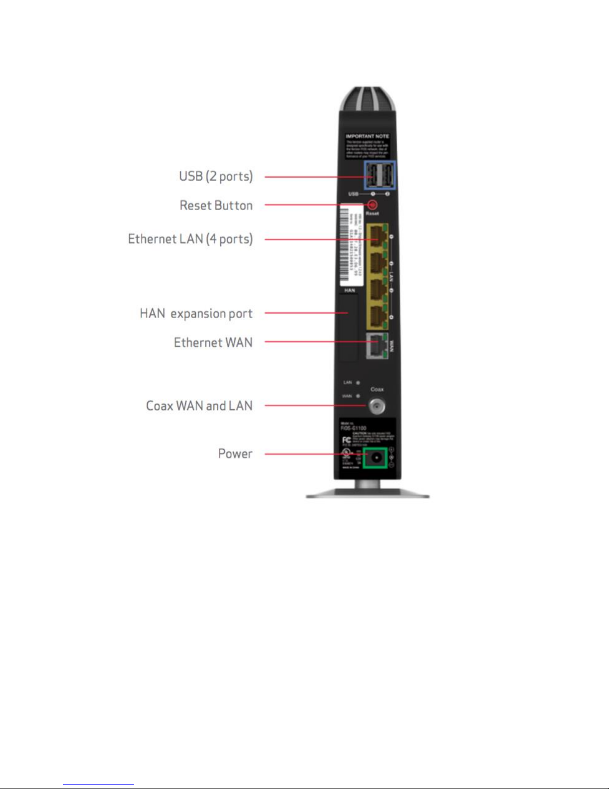
1.3c/ REAR PANEL
The rear panel of your Gateway has 8 ports; COAX, Ethernet LAN [4],
Ethernet WAN, and USB [2]. The rear panel also includes a DC power
jack and a reset button.
Copyright © 2016 Frontier Communications. All Rights Reserved.
GETTING TO KNOW YOUR GATEWAY
• USB - provides up to 500 mA at 5 VDC for attached devices.For
example, you could charge a cell phone. In the future, with a
firmware upgrade, the USB host functionality may be available for
other devices, such as external storage and cameras. Firmware
updates are performed automatically by Frontier.
Copyright © 2016 Frontier Communications. All Rights Reserved.

• Reset Button - allows you to reset your Gateway to the factory default
settings. To reset the Gateway, press and hold the Reset button
for at least three seconds.
• Ethernet LAN - connects devices to your Gateway using Ethernet
cables to join the local area network (LAN). The four Ethernet LAN
ports are 10/100/1000 Mbps auto-sensing and can be used with
either straight-through or crossover Ethernet cables.
• HAN Expansion Port - provides for future hardware upgrades to add
support for Home Area Networking capabilities.
• Ethernet WAN - connects your Gateway to the Internet using an
Ethernet cable.
• Coax WAN and LAN - connects your Gateway to the Internet and/or
to other MoCA devices using a coaxial cable. Warning: The WAN
Coax Port is intended for connection to FiOS only. It must not be
connected to any exterior or interior coaxial wires not designated for
FiOS.
• Power - connects your Gateway to an electrical wall outlet using the
supplied power adapter. Warning: The included power adapter is
for home use only, supporting voltages from 100-240Vac. Do not use in
environments with greater than 240Vac.
If you are replacing an existing wall mounted router, you do not need to
remove the mounting screws from the wall. The existing mounting
screws will fit the new bracket.
To mount your Gateway to a wall:
1. Remove the foot by turning the Gateway upside down and removing
the single screw that holds the foot to the Gateway.
Copyright © 2016 Frontier Communications. All Rights Reserved.

2. Slide the foot toward the front of the Gateway and pull the foot from
the holes. You may need to wiggle the foot slightly.
3. You may use the wall mount bracket as a template for positioning the
Gateway.
1.3d/ MOUNTING THE GATEWAY TO A WALL
GETTING TO KNOW YOUR GATEWAY
4. Mark the mounting holes, then remove the wall mount bracket from
the wall.
5. Drill holes for the screw anchors.
6. Insert the screw anchors in the holes in the wall,then insert the
screws intothe screw anchors and tighten the screws. Leave
screws extended about 0.2 inches from the wall.
7. Verify the screws are positioned correctly by placing the wall bracket
on the screws. Remove the wall bracket from the wall.
8. Place the Gateway on the wall bracket and slide the Gateway forward
until it locks in place.
Copyright © 2016 Frontier Communications. All Rights Reserved.

9. To secure the Gateway, attach the
bracketto the Gateway using the
single screw you removed from
the foot.
10. Slide the wallmount bracket with
the attached Gateway on the
screws, then slide the bracket
down until it locks in place.
Copyright © 2016 Frontier Communications. All Rights Reserved.

02/
CONNECTING YOUR GATEWAY
. 2.0 Setting Up Your Gateway
. 2.1 Computer Network Configuration
. 2.2 Main Screen
SETTING UP YOUR GATEWAY
Connecting your Gateway and accessing its
web-based Graphical User Interface (GUI) are
both simple procedures.
Accessing the GUI may vary slightly, depending
on your device’s operating system and web
browser.
Copyright © 2016 Frontier Communications. All Rights Reserved.

2.0/ SETTING UP YOUR GATEWAY
There are three basic steps to setting up your Gateway:
Step1: Connect your Gateway to the Internet
Step 2: Connect your network device to your Gateway
Step 3: Configure your Gateway
Before you begin, if you are replacing an existing Gateway, disconnect
it. Remove all old Gateway components, including the power supply.
They will not work with your new Gateway.
2.0a/ STEP 1 - CONNECT YOUR GATEWAY
1. Remove your Gateway, Ethernet cables, and power adapter from the
box.
2. Locate your high-speed Internet (WAN) outlet. This would be the wall
jack installed previously by Frontier. Note the type of jack may be
either Ethernet or coaxial.
3. Connect your Gateway to the Internet (WAN).
• If connecting the WAN using Ethernet, use the supplied white
Ethernet cable and plug one end into the white Ethernet WAN
port on the back of your Gateway. Plug the other end of the
cable into the high-speed Ethernet wall jack.
• If connecting the WAN using coaxial cable, locate a coaxial
cable and connect one end to the coax port on the back of your
Gateway. Connect the other end of the coaxial cable to a coax
wall jack.
Tighten the coaxial cables by hand until snug. The cables should
Copyright © 2016 Frontier Communications. All Rights Reserved.

not require a wrench.
4. Plug the power cord into the power port on the back of your Gateway
and then into a power outlet. The Gateway automatically turns on as
soon as power is plugged in.
Important: Wait until the Power/Internet light on the front of the Gateway
stops flashing and is solid white. If the light turns red, check the troubleshooting steps in the Troubleshooting section
of the user guide.
2.0b/ STEP 2 - CONNECT YOUR DEVICE TO YOUR GATEWAY
If connecting a device using wired Ethernet (preferred for initial setup):
• Plug one end of the supplied yellow Ethernet cable into one of the
four yellow Ethernet ports in the back of your Gateway.
Alternatively, you can use your own Ethernet cable of any color to
connect from the yellow Ethernet ports on the back of your
Gateway to your device with an Ethernet connector.
• Plug the other end of the yellow Ethernet cable into the Ethernet port
of your network device.
If connecting a wireless device:
• Access the Wi-Fi setting on your wireless device, then select your new
Gateway using the wireless network name (ESSID) shown on the
sticker located on the side of your Gateway.
• Enter the wireless password (WPA2 key) also shown on the sticker.
2.0c/ STEP 3 - CONFIGURE YOUR GATEWAY:
Copyright © 2016 Frontier Communications. All Rights Reserved.

1. Open a web browser on the device connected to your Gateway
network.
2. In the browser address field (URL), enter: myfiosgateway.com, then
press the Enter key on your keyboard. Alternately, you can enter:
https://192.168.1.1
SETTING UP YOUR GATEWAY
The first time you access your Gateway, an Easy Setup Wizard displays
to help step you through the setup process.
Copyright © 2016 Frontier Communications. All Rights Reserved.

3. In the Admin Password field, enter the password that is printed next
to the Administrator Password on the label on the side of your
Gateway.
4. Click Next. The Personalize Your Wi-Fi Settings screen displays. Click
on the check box next to Setup your Guest Wi-Fi (Optional) to
personalize your Guest Wi-Fi Name and Password.
For your protection, your Gateway is pre-set at the factory to use
WPA2/WPA mixed mode (Wi-Fi Protected Access) encryption for your
wireless network. This is the best setting for most users and provides
maximum security.
Copyright © 2016 Frontier Communications. All Rights Reserved.

SETTING UP YOUR GATEWAY AND COMPUTER
NETWORK CONFIGURATION
5. Click Continue. The Apply to Save Your Wi-Fi Settings screen appears.
You have an option of saving the Wi-Fi settingsas an image on your
device by clicking the Save as Picture button. After you click Save as
Picture to save your Wi-Fi settings as an image, click Apply to save the
Wi-Fi changes to your Gateway.
Important: If you are on a Wi-Fi device when setting up your Gateway, you
will be disconnected from the Wi-Fi network when you change the Wi-Fi
name or Wi-Fi password. When this occurs, your Gateway will detect this
situation and prompt you to reconnect using the new settings.
Copyright © 2016 Frontier Communications. All Rights Reserved.

Congratulations!
You’re All Set Up screen displays once your Gateway verifies the final
settings and has successfully connected to the Internet and is ready for
use. You can click on Main Router Settings to access the Main screen of
the Gateway or click on Start Browsing and you will be directed to the V
website.
If your Gateway is subsequently reset to the factory default settings,
the settings printed on the label will again be in effect.
If your Gateway fails to connect, follow the troubleshooting steps in the
Troubleshooting section of this guide.
2.1/ COMPUTER NETWORK CONFIGURATION
Each network interface on your computer should either automatically
obtain an IP address from the upstream Network DHCP server (default
configuration) or be manually configured with a statically defined IP
address and DNS address. We recommend leaving this setting as is.
COMPUTER NETWORK CONFIGURATION
2.1a/ CONFIGURING DYNAMIC IP ADDRESSING To configure a
Copyright © 2016 Frontier Communications. All Rights Reserved.

computer to use dynamic IP addressing:
1. In the Control Panel, locate Network and Internet, then select View
Network Status and Tasks.
2. In the View your active networks – Connect or disconnect section,
click Local Area Connection in the Connections field. The Local
Area Connection Status window displays.
3. Click Properties. The Local Area Connection Properties window
displays.
4. Select Internet Protocol Version 4 (TCP/IPv4), then click Properties.
The Internet Protocol Version 4 (TCP/IPv4) Properties window
displays.
5. Click the Obtain an IP address automatically radio button.
6. Click the Obtain DNS server address automatically radio button, then
click OK.
7. In the Local Area Connection Properties window, click OK to save the
settings.
8. To configure Internet Protocol Version 6 (TCP/IPv6) to use dynamic IP
addressing, repeat step 1 to 7. However for step 3, select Internet
Protocol Version 6 (TCP/IPv6) in the Properties option (refer to
IPv6 section for Gateway configuration).
MACINTOSH OS X
1. Click the Apple icon in the top left corner of the desktop. A menu
displays.
2. Select System Preferences. The System Preferences window displays.
Copyright © 2016 Frontier Communications. All Rights Reserved.

3. Click Network.
4. Verify that Ethernet, located in the list on the left, is highlighted and
displays Connected.
5. Click Assist Me.
6. Follow the instructions in the Network Diagnostics Assistant.
2.1b/ CONNECTING OTHER COMPUTERS & NETWORK DEVICES You
can connect your Gateway to other computers or set top boxes
using an Ethernet cable, wireless connection (Wi-Fi), or coaxial cable.
ETHERNET
1. Plug one end of an Ethernet cable into one of the open yellow
Ethernet ports on the back of your Gateway.
2. Plug the other end of the Ethernet cable into an Ethernet port on the
computer.
3. Repeat these steps for each computer to be connected to your
Gateway using Ethernet. You can connect up to four.
COMPUTER NETWORK CONFIGURATION
CONNECTING A WI-FI DEVICE USING WPS
Wi-Fi Protected Setup (WPS) is an easier way for many devices to set up
a secure wireless network connection. Instead of manually entering
passwords or multiple keys on each wireless client, such as a laptop,
printer, or external hard drive, your Gateway creates a secure wireless
network.
Copyright © 2016 Frontier Communications. All Rights Reserved.

In most cases, this only requires the pressing of two buttons – one on
your Gateway and one on the wireless client. This could be either a
built-in button or one on a compatible wireless adapter/card, ora
virtual button in software. Once completed, this allows wireless clients
to join your wireless network.
To initialize the WPS process, you can either press and release
the WPS button located on the front of your Gateway or use the
GUI and press the on-screen button.
You can easily add wireless devices to your wireless network using the
WPS option if your wireless device supports the WPS feature.
To access WPS using the user interface:
1. From the Main menu, select Wireless Settings, then select Wi-Fi
Protected Setup (WPS).
2. Enable the protected setup by moving the selector to On.
Copyright © 2016 Frontier Communications. All Rights Reserved.

3. Use one of the following methods:
• If your wireless client device has a WPS button, press the WPS button
on your Gateway, then click the WPS button on your wireless
device (client) to start the WPS registration process.
• If your client device has a WPS PIN, locate the PIN printed on the
client’s label or in the client documentation.
COMPUTER NETWORK CONFIGURATION AND
MAIN SCREEN
Enter the PIN number in the Client WPS PIN field. The Client WPS PIN
field is located in the section B - PIN Enrollment on the user interface.
Click Register.
• Alternatively, you can enter the Gateway’s PIN shown on this screen
into the WPS user interface of your device, if this PIN mode is
supported by your wireless device.
4. After pressing the WPS button on your Gateway, you have two
minutes to press the WPS button on the client device before the WPS
session times out.
When the WPS button on your Gateway is pressed, the Wireless light
on the front of your Gateway begins flashing white. The flashing
continues until WPS pairing to the client device completes successfully.
At this time, the Wireless light turns solid white.
If WPS fails to establish a connection to a wireless client device within
two minutes, the Wireless light on your Gateway flashes red for two
minutes to indicate the WPS pairing process was unsuccessful. After
flashing red, the light returns to solid white to indicate that Wi-Fi is on.
Copyright © 2016 Frontier Communications. All Rights Reserved.

CONNECTING A WI-FI DEVICE USING A PASSWORD
1. Verify each device that you are connecting wirelessly (using Wi-Fi) has
a built-in wireless or external wireless adapter.
2. Open the device’s wireless settings application.
3. Select your Gateway’s wireless network name (SSID) from the device’s
list of discovered wireless networks.
4. When prompted, enter your Gateway’s wireless password (WPA2
key) into the device’s wireless settings. Your Gateway’s default
wireless network name and wireless password are located are on
the sticker on the side of your Gateway.
5. Verify the changes were implemented by using the device’s web
browser to access a site on the Internet.
6. Repeat these steps for every device that you are wirelessly connecting
to your Gateway.
COAXIAL
1. Verify all coax devices are turned off.
2. Disconnect any adapter currently connected to the coaxial wall jack
in the room where your Gateway is located.
3. Connect one end of the coaxial cable to the coaxial wall jack and the
other end to the Coax port on your network device.
4. Power up the network device.
Copyright © 2016 Frontier Communications. All Rights Reserved.

2.2/ MAIN SCREEN
When you log into your Gateway, the page displays showing the Main
navigation menu at the top of the page and your Gateway’s Status,
including Quick Links, My Network, and Additional Resources display in
the body of the page.
Copyright © 2016 Frontier Communications. All Rights Reserved.

2.2a/ MENUThe Main menu links across the top of the page to the
following
configuration options and chapters:
• Wireless Settings - Chapter 3
• My Network - Chapter 5
• Firewall - Chapter 6
• Parental Controls - Chapter 7
• Advanced - Chapter 8
• System Monitoring - Chapter 9
2.2b/ STATUSThis section displays the status of your Gateway’s local
network (LAN)
and Internet connection (WAN).
BROADBAND CONNECTION
Broadband Connection displays the state of the broadband connection:
• Broadband interface: Ethernet or Coax
• Connected status: Connected or No Connection
• Connection Type: DHCP or Static
• WAN IP address: Address of the broadband connection QUICK LINKS
Quick Links contains frequently accessed documentation, such as
User Guide and Help, and settings, such as Change Wireless
Copyright © 2016 Frontier Communications. All Rights Reserved.

Settings, Change Admin Password, and Port Forwarding as well as
Logout. MY NETWORK My Network displays the connection
type, IP address, and status of all devices that have accessed or
are currently connected to the network.
Copyright © 2016 Frontier Communications. All Rights Reserved.

03/
WIRELESS SETTINGS
. 3.0 Overview
. 3.1 Wireless Status
. 3.2 Basic Security Settings
. 3.3 Advanced Security Settings
. 3.4 Wireless MAC Authentication
. 3.5 802.11 Mode
. 3.6 Other Advanced Wireless Options
. 3.7 Guest Wi-Fi Settings
OVERVIEW
Wireless networking enables you to free
yourself from wires and plugs, making
Copyright © 2016 Frontier Communications. All Rights Reserved.

your devices more accessible and easier to
use.
You can create a wireless network,
including accessing and configuring
wireless security options.
3.0/ OVERVIEW
Your Gateway provides you with wireless connectivity using the
802.11b, g, n, or ac standards. These are the most common wireless
standards.
802.11b has a maximum data rate of 11 Mbps, 802.11g has a maximum
data rate of 54 Mbps, 802.11n has a maximum data rate of 450 Mbps,
and 802.11ac has a maximum data rate of 1300 Mbps.
802.11b and g standards operate in the 2.4 GHz range. 802.11n
operates in both the 2.4 GHz and 5 GHz ranges. 802.11ac operates in
the 5 GHz range.
Note: 802.11 b is a legacy mode and is not recommended. Even one 802.11b
device connected to the network will slow your entire wireless network.
The wireless service and wireless security are activated by default. The
level of security is preset to WPA2 encryption using a unique default
WPA2 key (also referred to as a passphrase or password) preconfigured at the factory. This information is displayed on a sticker
located on the side of your Gateway.
Copyright © 2016 Frontier Communications. All Rights Reserved.

Your Gateway integrates multiple layers of security. These include
Wired Equivalent Privacy (WEP), Wi-Fi Protected Access (WPA/WPA2),
and firewall.
OVERVIEW
3.1/ WIRELESS STATUS
Use the Wireless Status feature to view the status of your Gateway’s
wireless network.
To view the status:
1. Access the Main page. You can quickly view your Gateway’s
wireless status in the My Network column. This includes all
devices that have recently accessed or are currently connected to
the network.
Copyright © 2016 Frontier Communications. All Rights Reserved.

2. Select the Wireless Settings icon. The Wireless Status page
displays additional wireless details.
WIRELESS STATUS
3. On the Wireless Status page for either 2.4 GHz or 5 GHz, the following
information displays:
• Radio Enabled - displays whether the wireless radio is active. When
the radio is not enabled, no wireless devices will be able to
connect to the home network.
• SSID - displays the SSID (Service Set Identifier) shared among all
devices on a wireless network. The SSID is the network name. All
devices must use the same SSID.
Copyright © 2016 Frontier Communications. All Rights Reserved.

• Channel - displays the channel the wireless connection is currently
using.
• Security Enabled - displays the type of security active on the wireless
connection as well as the security encryption key.
• SSID Broadcast - displays whether your Gateway is broadcasting its
SSID. If activated, the SSID of your Gateway wireless network is
broadcast wirelessly. If not activated, the SSID is hidden and the
wireless clients must be manually configured to use the SSID.
• MAC Authentication - displays whether your Gateway is using MAC
(Media Access Control) address authentication to allow wireless
devices to join the network.
• Wireless Mode - displays the types of wireless device that can join the
network.
• Packets Received/Sent - displays the number of packets received and
sent since the wireless capability was activated.
3.2/ BASIC SECURITY SETTINGS
You can configure the basic security settings for your Gateway’s
wireless network.
• WMM - displays if WMM is enabled on your Gateway.
WIRELESS STATUS AND BASIC SECURITY
SETTINGS
Copyright © 2016 Frontier Communications. All Rights Reserved.

To configure the basic security radio, SSID and channel settings:
1. On the Wireless Setting page, select Basic Security Settings.
2. To activate the wireless radio, click the On radio button.
Copyright © 2016 Frontier Communications. All Rights Reserved.

3. If desired, enter a new name for the wireless network in the SSID field
or leave the default name that displays automatically.
4. Select the channel you want the wireless radio to use to communicate
or accept the default Automatic channel, then select the Keep my
channel selection during power cycle check box to save your
channel selection when your Gateway is rebooted.
To configure the basic Wi-Fi Security settings, select a Security option:
WPA/WPA2 Mixed Mode
If WPA/WPA2 Mixed Mode (Wi-Fi Protected Access) was selected, the
WPA Key page displays. Selecting WPA/WPA2 Mixed Mode allows the
security mode to be automatically set by the gateway based on the
security capabilities of the client device. WPA/WPA2 mixed mode is the
default wireless security protocol.
To set the WPA/WPA2 Mixed Mode security:
Enter the Pre-Shared Key as a wireless password.
Copyright © 2016 Frontier Communications. All Rights Reserved.

BASIC SECURITY SETTINGS
2. To activate the group key update interval, select the Group Key
Update Interval check box and set the interval time in seconds.
3. Click Apply to save the changes.
WPA2
If WPA2 (Wi-Fi Protected Access II) was selected, the WPA2 page
displays.
To set the WPA2 security:
1. Enter the Pre-Shared Key.
2. To activate the group key update interval, select the Group Key
Update Interval check box and set the interval time in seconds.
3. Click Apply to save the changes.
Warning: WEP provides a low level of security and is not recommended.
Additionally, the WEP security setting will drop your Gateway’s wireless
performance to a maximum data rate of 54 Mbps, and will disable Wi-Fi
Protected Setup (WPS). WEP should only be enabled if you have wireless
client devices that don’t support WPA or WPA2.
WEP
If WEP was selected, the WEP Settings page displays.
Copyright © 2016 Frontier Communications. All Rights Reserved.

Note: Your Gateway’s recommended wireless security encryption is set to
WPA2. This is the factory default.
This section explains how to activate WEP (Wired Equivalent Privacy)
wireless security. WEP is a significantly less robust security compared to
WPA or WPA2 and is not recommended. To set up WPA2 wireless
security, refer to the WPA2 section.
To configure basic security to WEP:
5. To turn on WEP (Wired Equivalent Privacy) security, click the WEP
radio button.
6. Select a WEP security level as 64/40 bit or 128/104 bit.
Copyright © 2016 Frontier Communications. All Rights Reserved.

7. Enter the key code. If using a HEX key, each character
mustbealetterfromAtoForanumberfrom0to9.If the key is ASCII,
each character can be either any ASCII or alphanumeric character.
If using 64/40 bit, enter 10 HEX or 5 ASCII/alphanumeric
characters. If 128/104, enter 26 HEX or 13 ASCII/ alphanumeric
characters.
8. Be sure to write down the wireless settings for future use. Other
wireless devices that will be connected to your Gateway must be
configured to use these settings to join your Gateway’s wireless
network.
9. Click Apply to save changes.
You can change your advanced wireless security settings, such as
configuring wireless encryption to help protect your network from
unauthorized access or damage to your network devices; disable your
SSID broadcast to secure your wireless traffic; stop your Gateway from
broadcasting your SSID; set Wireless MAC Authentication to limit access
to specific wireless devices; and change the wireless mode to limit or
allow access to your wireless network based on the type of technology
as well as other advanced wireless options.
To modify the security settings for either 2.4 GHz or 5 GHz:
1. In the Wireless Settings page, select Advanced Security Settings.
3.3a/ LEVEL 1: SECURING YOUR NETWORKIn the Level 1 section,
select the type of wireless security. Depending
on your selection, one of the following pages displays.
3.3/ ADVANCED SECURITY SETTINGS
Copyright © 2016 Frontier Communications. All Rights Reserved.

ADVANCED SECURITY SETTINGS
3.3b/ LEVEL 1: SSID BROADCAST
You can configure your Gateway’s SSID broadcast capabilities to allow
or disallow wireless devices from automatically using a broadcast SSID
name to detect your Gateway wireless network.
To enable or disable SSID broadcast:
1. In the Advanced Settings page, locate the Level 2 section.
2. Click the 2.4 GHz SSID Broadcast or 5 GHz SSID Broadcast link for the
wireless network you wish to modify. The following example uses
the 2.4 GHz network. The display configuration looks basically the
same for the 5 GHz network.
Copyright © 2016 Frontier Communications. All Rights Reserved.

03/ WIRELESS SETTINGS
3. To enable SSID broadcasting, click the Enable radio button. SSID
broadcast is enabled by default. The SSID of the wireless network
will be broadcast to all wireless devices.
4. To disable SSID broadcasting, click the Disable radio button. The
public SSID broadcast will be hidden from all wireless devices. You
will need to manually configure additional wireless devices to join
the wireless network.
5. Click Apply to save the changes.
3.3c/ LEVEL 2: LIMIT ACCESS
You can configure your Gateway to limit access to your wireless
network allowing access only to those devices with specific MAC
addresses or based on the type of wireless technology used.
To limit access:
1. In the Advanced Settings page, locate the Level 2 section.
Copyright © 2016 Frontier Communications. All Rights Reserved.

2. To allow only devices with specific MAC addresses, clickthe Wireless
MAC Authentication link. The Wireless MAC Authentication page
displays. For additional details, refer to the Wireless MAC
Authentication section.
3. To limit access based on the type of technology, click the 802.11
b/g/n/ac Mode link. The 802.11 b/g/n/ac Mode page displays. For
additional details, refer to the 802.11 b/g/n/ac Mode section.
4. To access other advanced wireless options, click the Other Advanced
Wireless Options link. The Other Advanced Wireless Options page
displays. For additional details, refer to the Other Advanced
Wireless Options section.
3.4/ WIRELESS MAC AUTHENTICATIONYou can allow or deny
access to your wireless network by specifying
devices with specific MAC addresses.
To set wireless MAC authentication:
1. On the Advanced Settings page, locate the Level 2 section and click
the Wireless MAC Authentication link. The Wireless MAC
Authentication page displays.
2. To enable access control, select the Enable Access List check box.
3. Select either:
• Accept all devices listed below – allows only the listed devices
to access the wireless network. Warning: This will block
wireless network access for all devices not in the list. Only
devices in the list will be able to connect to the wireless network.
Copyright © 2016 Frontier Communications. All Rights Reserved.

• Deny all devices listed below – denies access to the listed
devices. All other wireless devices will be able to access the
wireless network if they use the correct wireless password.
Copyright © 2016 Frontier Communications. All Rights Reserved.

WIRELESS MAC AUTHENTICATION
6. To remove a specific device’s MAC address, click the Remove button
next to the specific MAC address.
7. When all changes are complete, click Apply to save changes.
3.5/ 802.11 MODE
From the 802.11 Mode page, you can limit the wireless access to your
network by selecting the 2.4 GHz and 5 GHz wireless communication
standard (mode) best suited or compatible with the devices you allow
access to your wireless network.
Enter the MAC address of a device, then click Add.
Repeat step 2 to add additional devices, as needed.
802.11 MODE
To select the 802.11 Mode:
Copyright © 2016 Frontier Communications. All Rights Reserved.

1. On the Advanced Settings page, locate the Level 2 section and click
the 802.11 Mode link. The 802.11 Mode page displays.
2. Select the 2.4 GHz Wireless Mode as follows:
• Compatibility – This is the default mode setting, providing a
good balance of performance and compatibility with existing
wireless devices. 802.11b, g, and n devices can connect.
• Legacy – For older wireless devices. Only 802.11b and g devices
can connect. 802.11b (legacy mode) will cause your wireless
network to slow and is not recommended.
• Performance – For newer wireless 802.11n devices only. No
other devices can be used.
3. Select the 5 GHz Wireless Mode as follows:
• N and AC Mode – This is the default setting. Both 802.11n and
802.11ac are available on the 5 GHz frequencies.
• AC Only Mode – This provides maximum performance. 802.11ac
devices will have exclusive use of the 5 GHz frequencies and
802.11n devices will not be able to connect at 5 GHz.
4. Click Apply to save the changes.
3.6/ OTHER ADVANCED WIRELESS OPTIONS
You can view additional wireless options.Comment: Recommend leaving
defaults as is unless otherwise directed.
To view the options:
Copyright © 2016 Frontier Communications. All Rights Reserved.

1. In the Advanced Settings page, locate the Level 2 section and click
Other Advanced Wireless Options link. A warning message
displays.
2. Click Yes. The Other Advanced Wireless Options page displays.
Comment: The following example uses the 2.4 GHz network. The
display configuration looks basically the same for the 5 GHz network.
OTHER ADVANCED WIRELESS OPTIONS
Copyright © 2016 Frontier Communications. All Rights Reserved.

3. View the following options:
Caution: These settings should only be configured by experienced network
technicians. Changing the settings could adversely affect the operation of
your Gateway and your local network.
WIRELESS SETTINGS
• Group Key Update Interval – time interval used to update the WPA
shared key (used to generate the group key)
• Transmission Rate – displays status as Auto
• Channel Width – Controls the bandwidth of the wireless signal
• Transmit Power – adjusts the power of the wireless signal
• CTS (Clear to Send) Protection Mode – allows mixed 802.11b/g/n/ac
networks to operate at maximum efficiency
• CTS Protection Type – displays cts, which is only for mixed
802.11b/g/n/ac networks or rts_cts, which is for 802.11a/b/g
networks
• Frame Burst – Max Number – allows packet bursting, which increases
overall network speed
• Frame Burst – Burst Time – indicates the burst time of the frame
bursts
• Beacon Interval – displays the time period of the beacon interval
• DTIM (Delivery Traffic Indication Message) Interval – provides a
countdown mechanism, informing wireless network clients of the
next window for listening to broadcast and multicast messages
Copyright © 2016 Frontier Communications. All Rights Reserved.

• Fragmentation Threshold – increases the reliability of frame
transmissions on the wireless network
OTHER ADVANCED WIRELESS OPTIONS
• RTS Threshold – controls the size of the data packet that the low level
RF protocol issues to an RTS packet
• MSDU Aggregation – enables or disables MSDU aggregation
• MPDU Aggregation – enables or disables MPDU aggregation
To access the WMM settings, click the WMM Settings link.
Click Apply to save changes.
3.6a/ WMM SETTINGSYou can prioritize the types of data
transmitted over the wireless
network using the advanced WMM settings.
Wireless QoS (WMM) can improve the quality of service (QoS) for
voice, video, and audio streaming over Wi-Fi by prioritizing these data
streams.
WMM Power Save can improve battery life on mobile Wi-Fi devices
such as smart phones and tablets by fine-tuning power consumption.
WMM (Wi-Fi Multimedia) QoS and Power Save require a wireless client
device which also supports WMM.
Note: The following example uses the 2.4 GHz network. The display
configuration looks basically the same for the 5 GHz network.
To set the options:
Copyright © 2016 Frontier Communications. All Rights Reserved.

In the Advanced Wireless Options page, click WMM Settings link. A
warning message displays.
1. To enable WMM Power Save, enable Wireless QoS (WMM) first, then
enable WMM Power Save by selecting the Enabled check box.
2. Click Apply to save changes.
3.7/ GUEST WI-FI SETTINGS
The Guest Wi-Fi network is designed to provide Internet connectivity to
your guests but restricts access to your primary network and shared
files. The primary network and the guest network are separated from
each other through firewalls. You create one Guest Wi-Fi SSID and one
password and use it for all guests. Guest Wi-Fi can be managed using
either the Gateway’s web interface, or via the My app.
Click Yes. The WMM Settings page displays.
To enable Wireless QoS (WMM), select the Enabled check box.
GUEST WI-FI SETTINGS
guest network SSID does not change when you make a change to your
primary network SSID.
Copyright © 2016 Frontier Communications. All Rights Reserved.

The Gateway is shipped from the factory with Guest Wi-Fi turned off.
The default SSID for Guest Wi-Fi is preconfigured at the factory to the
default wireless network name (ESSID) which is displayed on a sticker
located at the side of the router followed by hyphen guest (-Guest). For
example – if the router is shipped with a default SSID of “FiOS-ABCDE”
then the default SSID for Guest Wi-Fi is “FiOS-ABCDE-Guest”.
1. From the Main menu, select Wireless Settings, then select Guest Wi-Fi
Settings
2. Select the Guest Wi-Fi tab
3. Press the Edit button and enter a valid SSID and password
4. Press Save to save changes
3.7a/ GUEST WI-FI To enable Guest Wi-Fi:
Toggle the Guest Wi-Fi button to ON
Copyright © 2016 Frontier Communications. All Rights Reserved.

GUEST WI-FI SETTINGS
3.7b/ GUEST DEVICES
The devices on the Guest Wi-Fi network can be viewed on the Guest
Devices page. If the admin toggles the button next to a device to OFF,
that device will be blocked from accessing the Internet.
Copyright © 2016 Frontier Communications. All Rights Reserved.

04/
CONFIGURING MY NETWORK SETTINGS
. 4.0 Accessing My Network Settings
. 4.1 Using My Network Settings
ACCESSING MY NETWORK SETTINGS
You can configure the basic network
settings for your Gateway’s network.
My Network allows you to view and manage your network connections
and devices. You can block websites and Internet services, set port
forwarding, view device details, and rename devices.
To view your network connections:
1. On the Main page, select the My Network icon. The My Network page
opens with our current status displayed.
Copyright © 2016 Frontier Communications. All Rights Reserved.

Caution: The settings described in this chapter should only be configured by
experienced network technicians. Changes could adversely affect the
operation of your Gateway and your local network.
4.0/ ACCESSING MY NETWORK SETTINGS
USING MY NETWORK SETTINGS
4.1/ USING MY NETWORK SETTINGS
You can access and configure common network parameters:
• Block this Device - Click Block this Device to quickly enable/disable a
device from having Internet access.
• Website Blocking - To block specific websites, click Website Blocking.
Copyright © 2016 Frontier Communications. All Rights Reserved.

The Parental Controls page displays. For additional information
about blocking websites, refer to Chapter 7 Setting Parental
Controls.
• Block Internet Services - Internet services blocking prevents a device
on your network from accessing specific services, such as
receiving email or downloading files from FTP sites. Block Internet
services by locating the device, then clicking Block Internet
Services. The Access Control page displays. For additional
information on blocking Internet services, refer to the Access
Control section in Chapter 6 Configuring Security Settings.
• Port Forwarding - Port Forwarding allows your network to be exposed
to the Internet in specific limited and controlled ways.For
example, you could allow specific applications, such as gaming,
voice, and chat, to access servers in the local network. To access
the Port Forwarding page, click Port Forwarding. For additional
information, refer to the Port Forwarding section in Chapter 6
Configuring Security Settings.
• View Device Details - Click View Device Details to display the Device
Information page and view the selected device’s information,
such as IP Address, MAC address, Network Connection, Lease
Type, Port Forwarding Services, and Windows Shared Folder as
well as the Ping Test option. You can also click the device’s icon in
the Main page to display the Device Information page.
• Rename this Device - To change the name of a specific device, click
Rename this Device. The Rename Device page displays. If
desired, enter the new device name and/or select a different icon.
Click Apply to save changes. The My Network page will open with
the new name and icon displayed.
Copyright © 2016 Frontier Communications. All Rights Reserved.

05/
USING NETWORK CONNECTIONS
. 5.0 Accessing Network Connections
. 5.1 Network (Home/Office) Connection
. 5.2 Ethernet/Coax Connection
. 5.3 Wireless Access Point Connection
. 5.4 Broadband Ethernet/Coax Connection
Your Gateway supports various local area network
(LAN) and wide area network (WAN), or Internet
connections using Ethernet or coaxial cables.
You can configure aspects of the network and
Internet connections as well as create new
connections.
Copyright © 2016 Frontier Communications. All Rights Reserved.

ACCESSING NETWORK CONNECTIONS
Caution: The settings described in this chapter should only be configured by
experienced network technicians. Changes could adversely affect the
operation of your Gateway and your local network.
5.0/ ACCESSING NETWORK CONNECTIONSYou can access
your network connections and view the connections by
connection type.
To access the network connections:
1. Select My Network, then select Network Connections.
2. To display all connection entries, click the Advanced button.
Copyright © 2016 Frontier Communications. All Rights Reserved.

3. To view and edit the details of a specific network connection, click the
hyperlinked name or the action icon. The following sections detail the
types of network connections that you can view.
5.1/ NETWORK (HOME/OFFICE) CONNECTION
You can view the properties of your local network. This connection is
used to combine several network interfaces under one virtual network.
For example, you can create a home/office network connection for
Ethernet and other network devices.
NETWORK (HOME/OFFICE) CONNECTION
Note: When a network connection is disabled, the formerly underlying
devices connected to it will not be able to obtain a new DHCP address from
that Gateway network interface.
To view the connection:
1. On the Network Connections page, click the Network (Home/Office)
Copyright © 2016 Frontier Communications. All Rights Reserved.

connection link. The Network (Home/Office) Properties page
displays.
2. To rename a network connection, enter the new network name in the
Name field.
3. Click Apply to save the changes.
CONFIGURING THE HOME/OFFICE NETWORK
To configure the network connection:
1. In the Network (Home/Office) Properties page, click Settings. The
configuration page displays.
Copyright © 2016 Frontier Communications. All Rights Reserved.

2. Configure the following sections, as needed.
GENERALIn the General section, verify the following information:
• Status - displays the connection status of the network.
NETWORK (HOME/OFFICE) CONNECTION
• Network – displays the type of network connection.
• Connection Type - displays the type of connection.
• Physical Address - displays the physical address of the network card
used for the network
• MTU - specifies the Maximum Transmission Unit (MTU) specifies the
largest packet size permitted for Internet transmissions:
Copyright © 2016 Frontier Communications. All Rights Reserved.

– Automatic - sets the MTU at 1500
– Automatic by DHCP - sets the MTU according to the
DHCP connection
– Manual - allows you to manually set the MTU
• Internet Protocol - in the internet protocol section, specify one of the
following
– Use the Following IP Address - the network connection uses a
permanent or static IP address and subnet mask address, provided by
an experienced network technician.
BRIDGE
In the Bridge section of the Configure Network (Home/Office), you can
configure the various LAN interfaces. By default, the Ethernet, Coax,
and Wireless Access Point connections are included in the ‘Network
(Home/Office)’ bridge.
Caution: Do not change these settings unless specifically instructed to by
Frontier. Changes could adversely affect the operation of your Gateway and
your local network.
Copyright © 2016 Frontier Communications. All Rights Reserved.

Verify the following information:
• Status – displays the connection status of a specific network
connection.
• Action – contains an icon that, when clicked, generates the next
lower-level configuration page for the specific network
connection or network device. IP ADDRESS DISTRIBUTION The
IP Address Distribution section of the Properties settings is used
to configure your Gateway’s Dynamic Host Configuration Protocol
(DHCP) server parameters.
NETWORK (HOME/OFFICE) CONNECTION
Once enabled and configured, the DHCP server automatically assigns IP
addresses to any network devices which are set to obtain their IP
address dynamically.
If DHCP Server is enabled on your Gateway, configure the network
devices as DHCP Clients. There are 2 basic options in this section:
Copyright © 2016 Frontier Communications. All Rights Reserved.

Disabled and DHCP Server.
To set up the Gateway’s network bridge to function as a DHCP server:
1. In the IP Address Distribution section, select the DHCP server. Once
enabled, the DHCP server provides automatic IP assignments (also
referred to as IP leases) based on the preset IP range defined below.
• Start IP Address – Enter the first IP address in the IP range that the
Gateway will automatically begin assigning IP addresses from. Since
your Gateway’s IP address is 192.168.1.1, the default Start IP Address is
192.168.1.2.
• End IP Address – Enter the last IP address in the IP range that the
Gateway will automatically stop the IP address allocation at. The
maximum end IP address range that can be entered is 192.168.1.254.
2. If Windows Internet Naming Service (WINS) is being used, enter the
WINS server address.
3. In the Lease Time in Minutes field, enter the amount of time a
network device is allowed to connect to the Gateway with its
currently issued dynamic IP address.
4. Click Apply to save changes.
ROUTING
You can configure your Gateway to use static or dynamic routing.
• Static routing – specifies a fixed routing path to neighboring
destinations based on predetermined metrics.
• Dynamic routing – automatically adjusts how packets travel on the
network. The path determination is based on network/device
Copyright © 2016 Frontier Communications. All Rights Reserved.

reachability and status of network being traveled. To configure
routing:
1. In the Routing Table section, click Add New Route to display and
modify the new route configuration page.
NETWORK (HOME/OFFICE) CONNECTION
COMPLETE NETWORK CONNECTION CONFIGURATION UPDATES To
save your changes click Apply.
5.2/ BROADBAND CONNECTION
You can view the properties of your broadband connection (your
connection to the Internet). This connection may be via either Ethernet
or Coaxial cable.
To view the connection settings:
Copyright © 2016 Frontier Communications. All Rights Reserved.

1. In the Network Connections page, click the Broadband Connection
(Ethernet/Coax) link.
2. To rename the network connection, enter the new name in the Name
field.
3. Click Apply to save changes.
ETHERNET/COAX CONNECTION
5.2a/ CONFIGURING THE ETHERNET/COAX CONNECTION To
configure the connection:
Copyright © 2016 Frontier Communications. All Rights Reserved.

1. In the Broadband Connection (Ethernet/Coax) Properties page, click
Settings. The configuration page displays.
2. Configure the following settings, as needed.
GENERAL
Verify the following information:
• Status - displays the connection status of the network.
• Network – displays the type of network connection.
• Connection Type - displays the type of connection.
• Physical Address - displays the physical address of the network card
used for the network.
– Automatic - sets the MTU (Maximum Transmission Unit at
1500)
– Automatic by DHCP - sets the MTU according to the DHCP
Copyright © 2016 Frontier Communications. All Rights Reserved.

connection
– Manual - allows you to manually set the MTU to be set.
COAX LINK To set the Channel:
1. Select the coax link channel as 1 to 3.
2. Select the On or Off radio button in the Auto Detection field.
3. To set privacy, select the Enabled check box. This causes all devices
connected to the coaxial cable to use the same password. This is
recommended.
4. To set the password, enter the Coax Link password in the Password
field.
• MTU - specifies the largest packet size permitted for Internet
transmissions:
ETHERNET/COAX CONNECTION
5. To enable or disable the Coax link, click Disable or Enable.
6. To view the devices connected using the coaxial cable, click the Go to
Copyright © 2016 Frontier Communications. All Rights Reserved.

WAN Coax Stats link.
COMPLETE ALL ETHERNET/COAX CONNECTION
CONFIGURATION UPDATES
To save your changes:
1. Click Apply.
5.3/ WIRELESS ACCESS POINT CONNECTION
A Wireless Access Point network connection allows wireless devices to
connect to the local area network (LAN) using the 2.4 GHz or 5 GHz WiFi network.
Note: Once disabled, all wireless devices connected to that wireless network
will be disconnected from the LAN network and Internet.
To view the connection:
1. In the Network Connections page, click Advanced.
Copyright © 2016 Frontier Communications. All Rights Reserved.

2. Click 5 GHz Wireless Access Point 1 or 2.4 GHz Wireless Access Point
WIRELESS ACCESS POINT CONNECTION
3. To disable the connection, click Disable.
4. To rename the connection, enter a name in the Name field.
5. Click Apply to save the changes.
6. Reboot your Gateway.
5.3a/ CONFIGURING WIRELESS ACCESS POINT PROPERTIES To
configure the connection:
1. In the Wireless Access Point Properties page, click Settings. The
configuration page displays.
Copyright © 2016 Frontier Communications. All Rights Reserved.

2. Verify the following information:
• Status - displays the connection status of the network.
• Network – displays the type of network connection.
• Connection Type - displays the type of connection.
• Physical Address - displays the physical address of the network card
used for the network.
• MTU - specifies the largest packet size permitted for Internet
transmissions:
– Automatic - set the MTU (Maximum Transmission Unit) at 1500
– Automatic by DHCP - sets the MTU according to the DHCP connection
Copyright © 2016 Frontier Communications. All Rights Reserved.

WIRELESS ACCESS POINT CONNECTION AND
BROADBAND ETHERNET/COAX CONNECTION
– Manual - allows you to manually set the MTU 3. Click Apply to save
changes.
5.4/ BROADBAND ETHERNET/COAX CONNECTION
A Broadband Ethernet connection connects computers to your
Gateway using Ethernet cables. The connections are either direct or use
network hubs and switches.
A Coax connection connects devices, such as set-top boxes, to your
Gateway using a coaxial cable.
Note: If disabling the connection, you must reboot your Gateway for the
change to take effect.
To view the connection:
1. In the Network Connections page, click the Broadband Connection
(Ethernet/Coax) link.
Copyright © 2016 Frontier Communications. All Rights Reserved.

2. To rename the network connection, enter the new name in the Name
field.
3. Click Apply to save changes.
5.4a/ CONFIGURING THE ETHERNET/COAX CONNECTION To
configure the connection:
1. In the Broadband Connection (Ethernet/Coax) Properties page, click
Settings. The configuration page displays.
2. Configure the following settings, as needed.
GENERAL
Verify the following information:
• Status - displays the connection status of the network
• Network – displays the type of network connection
Copyright © 2016 Frontier Communications. All Rights Reserved.

• Connection Type - displays the type of connection
• Physical Address - displays the physical address of the network card
used for the network
• MTU - specifies the largest packet size permitted for Internet
transmissions:
– Automatic - set the MTU (Maximum Transmission Unit) at 1500
– Automatic by DHCP - sets the MTU according to the DHCP
connection
– Manual - allows you to manually set the MTU COAX LINK
1. To set the Channel, select the coax link channel as 1 to 3.
2. Select the On or Off radio button in the Auto Detection field.
3. To set privacy, select the Enabled check box. This causes all devices
connected to the coaxial cable to use the same password. This is
recommended.
4. To set the password, enter the Coax Link password in the Password
field.
5. To enable or disable the Coax link, click Disable or Enable.
6. To view the devices connected using the coaxial cable, click the Go to
WAN Coax Stats link.
BROADBAND ETHERNET/COAX CONNECTION
Copyright © 2016 Frontier Communications. All Rights Reserved.

INTERNET PROTOCOL
1. In the Internet Protocol section, specify one of the following:
• No IP Address – the connection has no IP address. This is useful
if the connection operates under a bridge.
• Obtain an IP Address Automatically – the network connection is
required to obtain an IP address automatically. The server
assigning the IP address also assigns a subnet mask address,
which can be overridden by entering another subnet mask
address.
• Use the Following IP Address - the network connection uses a
permanent or static IP address, then the IP address and
subnet mask address.
2. To override the subnet mask, select the Override Subnet Mask check
box, then enter the new subnet mask.
ROUTING MODE
COMPLETE ALL ETHERNET/COAX CONNECTION CONFIGURATION
UPDATES
To save your changes:
1. Click Apply.
Copyright © 2016 Frontier Communications. All Rights Reserved.

Copyright © 2016 Frontier Communications. All Rights Reserved.

06/
CONFIGURING SECURITY SETTINGS
. 6.0 Firewall
. 6.1 Access Control
. 6.2 Port Forwarding
. 6.3 Port Triggering
. 6.4 DMZ Host
. 6.5 Remote Administration
. 6.6 Static NAT
. 6.7 Security Log
Your Gateway’s security suite includes
comprehensive and robust security
services, such as stateful packet inspection,
firewall security, user authentication
Copyright © 2016 Frontier Communications. All Rights Reserved.

protocols, and password protection
mechanisms.
These and other features help protect your
computers from security threats on the
Internet.
FIREWALL
This chapter covers the following security features:
• Firewall - select the security level for the firewall.
• Access Control - restrict access from the local network to the
Internet.
• Port Forwarding - enable access from the Internet to specified
services provided by computers on the local network.
• Port Triggering - define port triggering entries to dynamically open
the firewall for some protocols or ports.
• DMZ Host - allows a single device on your primary network to be fully
exposed to the Internet for special purposes such as Internet
Gaming.
• Remote Administration - enable remote configuration of your
gateway from any Internet-accessible computer.
• Static NAT - allow multiple static NAT IP addresses to be designated to
devices on the network.
Copyright © 2016 Frontier Communications. All Rights Reserved.

• Security Log - view and configure the security log.
6.0/ FIREWALL
The firewall is the cornerstone of the security suite for your Gateway. It
has been exclusively tailored to the needs of the residential or office
user and is pre-configured to provide optimum security. The firewall
provides both the security and flexibility home and office users seek. It
provides a managed, professional level of network security while
enabling the safe use of interactive applications, such as Internet
gaming and video conferencing.
Additional features, including surfing restrictions and access control,
can also be configured locally through the user interface or remotely by
a Frontier.
The firewall regulates the flow of data between the local network and
the Internet. Both incoming and outgoing data are inspected, then
either accepted and allowed to pass through your Gateway or rejected
and barred from passing through your Gateway, according to a flexible
and configurable set of rules. These rules are designed to prevent
unwanted intrusions from the outside, while allowing local network
users access to Internet services.
The firewall rules specify the type of services on the Internet that are
accessible from the local network and types of services in the local
network that are accessible from the Internet.
Each request for a service that the firewall receives is checked against
the firewall rules to determine whether the request should be allowed
to pass through the firewall. If the request is permitted to pass, all
subsequent data associated with this request or session is also allowed
to pass, regardless of its direction.
Copyright © 2016 Frontier Communications. All Rights Reserved.

For example, when accessing a website on the Internet, a request is
Security Level
Internet Requests
Incoming Traffic
Local Network
Requests
Outgoing Traffic
Maximum
Blocked
Limited
Typical
Blocked
Unrestricted
sent to the Internet for this site. When the request reaches your
Gateway, the firewall identifies the request type and origin, such as
HTTP and a specific computer in the local network. Unless your
Gateway is configured to block requests of this type from this
computer, the firewall allows this type of request to pass to the
Internet.
When the website is returned from the web server, the firewall
associates the website with this session and allows it to pass;
FIREWALL
regardless HTTP access from the Internet to the local network is
blocked or permitted.
It is the origin of the request, not subsequent responses to this request,
which determines whether a session can be established.
6.0a/ SETTING FIREWALL CONFIGURATION
You can select a maximum, typical, or minimum security level to block,
limit, or permit all traffic. The following table shows request access for
each security level.
Copyright © 2016 Frontier Communications. All Rights Reserved.

Minimum
Unrestricted
Unrestricted
The request access is defined as:
• Blocked traffic - no access allowed, except as configured in Port
Forwarding and Remote Access
• Limited - permits only commonly used services, such as email and
web browsing
• Unrestricted - permits full access of incoming traffic from the Internet
and allows all outgoing traffic, except as configured in Access
Control
1. From the Firewall General settings page click on desired IPv6 option
to configure IPv6 security:
6.0b/ SPECIFYING GENERAL SETTINGS FOR IPV4 OR IPV6 To set your
firewall configuration:
Copyright © 2016 Frontier Communications. All Rights Reserved.

2. Select a security level by clicking one of the radio buttons. Using the
Minimum Security setting may expose the local network to
significant security risks, and should only be used for short periods
of time to allow temporary network access.
3. Click Apply to save changes.
Copyright © 2016 Frontier Communications. All Rights Reserved.

6.1/ ACCESS CONTROL
You can block individual computers on your local network from
accessing specific services on the Internet. For example, you could
block one computer from accessing the Internet, then block a second
computer from transferring files using FTP as well as prohibit the
computer from receiving incoming email.
Access control incorporates a list of preset services, such as applications
and common port settings.
6.1a/ ALLOW OR RESTRICT SERVICES To allow or restrict services:
1. From the Firewall page, select Access Control. The Access Control
page opens with the Allows and Blocked sections displayed. The
Allowed section only displays when the firewall is set to maximum
security.
3. To block a service, click Add. The Add Access Control Rule page
displays.
Copyright © 2016 Frontier Communications. All Rights Reserved.

ACCESS CONTROL AND PORT FORWARDING
3. To apply the rule to:
• All networked devices - select Any.
• Specific devices only - select User Defined, then click Add and
create a network object.
4. In the Protocol field, select the Internet protocol to be allowed or
blocked. If the service is not included in the list, select User
Defined. The Edit Service page displays. Define the service, then
click OK. The service is automatically added to the Add Access
Control Rule section.
5. Specify when the rule is active as Always or User Defined and click
Add to create the schedule.
6. Click Apply to save changes. The Access Control page displays a
summary of the new access control rule.
Copyright © 2016 Frontier Communications. All Rights Reserved.

6.1b/ DISABLE ACCESS CONTROL
You can disable an access control and enable access to the service
without removing the service from the Access Control table. This can
make the service available temporarily and allow you to easily reinstate
the restriction later.
• To disable an access control, clear the check box next to the service
name.
• To reinstate the restriction, select the check box next to the service
name.
• To remove an access restriction, select the service and click Remove.
The service is removed from the Access Control table.
6.2/ PORT FORWARDING
You can activate port forwarding to expose the network to the Internet
in a limited and controlled manner. For example, enabling applications,
such as gaming and voice, to work from the local network as well as
allowing Internet access to servers within the local network.
To create port forwarding rules:
1. From the Firewall page, select Port Forwarding. The Port Forwarding
page opens with the current rules displayed.
Copyright © 2016 Frontier Communications. All Rights Reserved.

PORT FORWARDING AND PORT TRIGGERING
2. To create a new rule, select the IP address in the Select IP from Menu
drop down.
3. Select the application in the Application to Forward drop down.
4. Click Add. The rule displays in the Applied Rules section.
5. Click Apply to save changes.
6.2a/ ADVANCED PORT FORWARDING RULES You can configure
advanced port forwarding rules. To configure the rules:
1. In the Port Forwarding page, select Advanced.
Copyright © 2016 Frontier Communications. All Rights Reserved.

2. If needed, to select a port to forward communication to, select an
option in the Forward to Port list box.
3. If a single port or range of ports is selected, a text box displays. Enter
the port numbers.
4. To schedule the rule, select either Always or User Defined in the
Schedule list box.
5. Click Add. The rule displays in the Applied Rules section.
6. Click Apply to save changes.
6.3/ PORT TRIGGERING
Port triggering can be described as dynamic port forwarding. By setting
port triggering rules, inbound traffic arrives at a specific network host
using ports that are different than those used for outbound traffic. The
outbound traffic triggers the ports where the inbound traffic is
directed.
Copyright © 2016 Frontier Communications. All Rights Reserved.

For example, a gaming server is accessed using UDP protocol on port
2222. The gaming server then responds by connecting the user using
UDP on port 3333, when a gaming session is initiated.
In this case, port triggering must be used since it conflicts with the
following default firewall settings:
• Firewall blocks inbound traffic by default.
• Server replies to your Gateway IP, and the connection is not sent back
to the host since it is not part of a session.
PORT TRIGGERING AND REMOTE
ADMINISTRATION
To resolve the conflict, a port triggering entry must be defined, which
allows inbound traffic on UDP port 3333 only after a network host
generated traffic to UDP port 2222. This results in your Gateway
accepting the inbound traffic from the gaming server and sending it
back to the network host which originated the outgoing traffic to UDP
port 2222.
To configure port triggering:
1. Select Port Triggering.
Copyright © 2016 Frontier Communications. All Rights Reserved.

2. To add a service as an active protocol, click Add. The Edit Port
Triggering Rule page displays.
Copyright © 2016 Frontier Communications. All Rights Reserved.

3. Enter the service name then configure its inbound and outbound
trigger ports. Click Apply to save User Defined changes. The Port
Triggering page displays.
4. Click Apply again to save all changes.
6.4/ DMZ HOST
DMZ Host allows a single device on your primary network to be fully
exposed to the Internet for special purposes like Internet gaming.
DMZ HOST
Warning: Enabling DMZ Host is a security risk. When a device on your
network is a DMZ Host, it is directly exposed to the Internet and loses much
of the protection of the firewall. If it is compromised, it can also be used to
attack other devices on your primary network.
Follow these steps to designate a device on your primary network as a
DMZ Host:
1. From the Firewall page, select DMZ Host
2. Select Enable for the DMZ Host
3. Enter the IP address of the device you want to designate as the DMZ
Host
4. Click Apply
Copyright © 2016 Frontier Communications. All Rights Reserved.

6.5/ REMOTE ADMINISTRATION
Caution: Enabling Remote Administration places your Gateway network at
risk from outside attacks.
You can access and control your Gateway not only from within the local
network, but also from the Internet using Remote Administration.
You can allow incoming access to the following:
• Web Management - used to obtain access to your Gateway’s GUI and
gain access to all settings and parameters through a web browser.
• Diagnostic Tools - used for troubleshooting and remote system
management by a user or your Frontier. Web Management
Copyright © 2016 Frontier Communications. All Rights Reserved.

remote administration access may be used to modify or disable
firewall settings. Local IP addresses and other settings can also be
changed, making it difficult or impossible to access your Gateway
from the local network. Remote administration accessto SSH or
Web Management services should be activated only when
absolutely necessary. Note: Encrypted remote administration is
performed using a secure SSL connection and requires a SSL certificate.
When accessing your Gateway for the first time using encrypted
remote administration, a warning page opens with a certificate
authentication message displayed. This is due to your Gateway SSL
certificate being self-generated. When this message display under that
circumstance, ignore the message and continue. Even though this
message displays, the self-generated certificate is safe and provides a
secure SSL connection.
REMOTE ADMINISTRATION AND STATIC NAT
To enable remote administration:
1. Select Remote Administration.
2. To enable access, select the check box.
3. Click Apply to save changes.
4. To remove access, clear the check box.
5. Click Apply again to save changes.
Static NAT allows devices located behind a firewall that is configured
with private IP addresses to appear to have public IP addresses to the
Internet. This allows an internal host, such as a web server, to havean
unregistered (private) IP address and still be accessible over the
Copyright © 2016 Frontier Communications. All Rights Reserved.

Internet.
To configure static NAT:
1. Select Static NAT.
2. To create a static NAT, click Add. The Add NAT/NAPT Rule page
displays.
6.6/ STATIC NAT
STATIC NAT AND SECURITY LOG
3. Select a source address in the Specify Address field or enter an IP
address in the text box.
4. Enter the public IP address.
5. If using port forwarding, select the Enable Port Forwarding for Static
NAT check box.
6. Click Apply to save changes.
7. Repeat these steps to add additional static IP addresses.
6.7/ SECURITY LOG
You can view events that your firewall has blocked by accessingthe
security log. Your Gateway reports events, such as attempts to establish
inbound and outbound connections, attempts to authenticate at an
administrative interface, such as your Gateway GUI, firewall
configuration, and system start-up.
• Time - based on the date and time in your Gateway
Copyright © 2016 Frontier Communications. All Rights Reserved.

• Event Type - consists of firewall information, firewall setup, and
system log
• Log Level - describes the event that occurred, such as a fragmented
packet or parental controls.
• Details - provide a reason the event occurred, such as a packet has
been blocked because of parental controls. You can modify the
type of events that display in the security log. This does not
modify the event itself. It simply changes the information that
displays in the log. 6.7a/ EVENT TYPES The security log records
the following event types:
• Access control – a packet has been accepted/blocked due to an access
control rule.
• Advance filter rule – a packet has been accepted/blocked due to an
advanced filter rule.
• ARP – an ARP packet has been accepted.
• AUTH:113 request - an outbound packet for AUTH protocol has been
accepted (for maximum security level).
• Broadcast/Multicast protection – a packet with a broadcast/ multicast
source IP has been blocked.
The security log reports the following information:
SECURITY LOG
• Default policy – a packet has been accepted/blocked according to the
default policy.
Copyright © 2016 Frontier Communications. All Rights Reserved.

• Defragmentation failed – the fragment has been stored in memory
and blocked until all fragments have arrived and defragmentation
can be performed.
• DHCP request – your Gateway sent a DHCP request (depends on the
distribution).
• DHCP response - your Gateway sent a DHCP response (depends on the
distribution).
• Echo/Chargen/Quote/Snork protection – a packet has been blocked
due to Echo/Chargen/Quote/Snork protection.
• Firewall internal – from the firewall internal mechanism, event type is
recorded and an accompanying explanation will be added.
• Firewall rules were changed – the rule set has been modified.
• Firewall status changed – the firewall status changed from up to
down or vice versa, as specified in the event type description.
• First packet in connection is not a SYN packet – a packet has been
blocked due to a TCP connection that started without a SYN
packet.
• Fragmented packet – a fragment has been rejected.
• Fragmented packet, bad align – a packet has been blocked because,
after defragmentation, the packet was badly aligned.
• Fragmented packet, header too big – a packet has been blocked
because, after defragmentation, the header was too big.
• Fragmented packet, header too small – a packet has been blocked
Copyright © 2016 Frontier Communications. All Rights Reserved.

because, after defragmentation, the header was too small.
• Fragmented packet, overlapped – a packet has been blocked because,
after defragmentation, there were overlapping fragments.
• Fragmented packet, packet exceeds – a packet has been blocked
because, after defragmentation, the packet exceeded.
• Fragmented packet, packet too big – a packet has been blocked
because, after defragmentation, the packet was too big.
• FTP port request to 3rd party is forbidden – possible bounce attack – a
packet has been blocked.
• ICMP flood protection – a broadcast ICMP (Internet Control Message
Protocol) flood.
• ICMP protection – a broadcast ICMP message has been blocked.
• ICMP redirect protection – an ICMP redirected message has been
blocked.
• ICMP replay – an ICMP replay message has been blocked.
• Illegal packet options – the options field in the packet’s header is
either illegal or forbidden.
• IP Version 6 – an IPv6 packet has been accepted.
• Malformed packet: Failed parsing – a packed has been blocked
because it is malformed.
• Maximum security enabled service – a packet has been accepted
because it belongs to a permitted service in the maximum security
Copyright © 2016 Frontier Communications. All Rights Reserved.

level.
• Fragmented packet, no memory – a packet has been blocked because
there is no memory for fragments.
SECURITY LOG
• Multicast IGMP connection – a multicast packet has been accepted.
• NAT Error: Connection pool is full - No connection created – a
connection has not been created because the connection pool is
full.
• NAT Error: Conflict mapping already exists – a conflict occurred
because the NAT mapping already exists, so NAT failed.
• NAT Error: No free NAT IP – no free NAT IP, so NAT has failed.
• NAT out failed – NAT failed for this packet.
• Outbound Auth1X – an outbound Auth1X packet has been accepted.
• Packet invalid in connection – an invalid connection packet has been
blocked.
• Parental controls – a package has been block because of parental
controls.
• Passive attack on ftp-server: Client attempted to open Server ports – a
packet has been blocked.
• Service – a packet has been accepted because of a certain service, as
specified in the event type.
Copyright © 2016 Frontier Communications. All Rights Reserved.

• Spoofing protection – a packet from the Internet with a source IP
belong to the local network has been blocked.
• STP packet – STP (Spanning Tree Protocol) packet has been
accepted/rejected.
• SynCookies protection – a SynCookies packet has been blocked.
• Trusted device – a packet from a trusted device has been accepted.
• UDP flood protection – a packed has been blocked, stopping a UDP
flood.
• User authentication – a message arrived during login time, including
both successful and failed authentication.
• Wildcard connection hooked – debug message regarding connection.
• Wildcard connection opened - debug message regarding connection.
• WinNuke protection – a WinNuke attack has been blocked. To view
the security log:
1. Select Security Log.
2. To modify the types of events that display in the log, click
Settings.
SECURITY LOG
Copyright © 2016 Frontier Communications. All Rights Reserved.

3. In the Accepted Events section, select the type of activities that
generates a log message:
• Accepted Incoming Connections – generates a log message for each
successful attempt to establish an inbound connection to the local
network.
Copyright © 2016 Frontier Communications. All Rights Reserved.
 Loading...