

Page 1

OPERATOR'S MANUAL
DISK MOWER
DM1160
9N004AUS F
- English (USA) - 12-2012
Page 2

Page 3

Dear Owner
1
DM1160
$DEAR OWNER
In buying a Frontier machine you have chosen wisely. Into it have gone years of thought, research and
improvement. You will find, as have thousands of owners all over the world, that you have the best that
engineering skill and actual field testing can produce. You have purchased a dependable machine, but only
through proper care and operation can you expect to receive the performance and long service built into it.
This manual contains all the necessary information for you to receive full efficiency from your machine. The
performance you get from this machine is largely dependent on how well you read and understand this manu al
and apply this knowledge. Please DO NOT ASSUME YOU KNOW HOW TO OPERATE AND MAINTAIN YOUR
MACHINE before reading this manual carefully. KEEP THIS MANUAL AVAILABLE FOR REFERENCE. Pass
it on to the next owner if you re-sell the machine.
Your John Deere dealer can offer a complete line of original manufacturer service parts. These parts are
manufactured and carefully inspected in the same factory that builds the machine to assure high quality and
accurate fitting of any necessary replacements.
About improvements
We are continually striving to improve our products. We therefore reserve the right to make improvements or
changes when it becomes practical to do so, without incurring any obligations to make changes or additions to
the equipment sold previously.
Wearing parts
Wearing parts fitted on our machines have been tested in very different situations to optimize their service life.
Nevertheless, the service life depends highly on the conditions of use (products to handle, soil, weather
conditions, etc...).
Designated use of the machine
The DM1160 mower must only be used for the purpose for which it was manufactured: mowing on the g rou nd
of hay fields, grass silage fields and improved pastures for the purpose of harvesting fodder for feeding
livestock.
Page 4

2
Contents
DM1160
$CONTENTS
Dear Owner.....................................................................................................................1
Contents .........................................................................................................................2
Identification of the machine........................................................................................4
Front view......... ... ... ... .... ............................................................................. ... .... ... ... ... .......................4
Rear view...........................................................................................................................................4
Model identification plate.................................................................................................................5
Optional equipment................................................................ ... ... .... ... ... ... ... .... ... ... ... .......................5
Safety..............................................................................................................................6
Description of symbols used in this document.............................................................................6
Safety instructions............................................................................................................................7
Location and description of safety decals on the machine........................................................16
Machine specifications................................................................................................21
Description and glossary...............................................................................................................21
Technical specifications.................................................................................................................22
Sound levels....................................................................................................................................22
Putting into service......................................................................................................23
Description of control elements....................................................................................................23
Coupling and uncoupling...............................................................................................................23
Instructions for transport............................................................................................34
Putting the machine into transport position ................................................................................34
Conformity with the road regulations...........................................................................................36
Page 5

Contents
3
DM1160
Instructions for work....................................................................................................37
Putting the machine into work position .......................................................................................37
Adjustments in working position..................................................................................................39
Machine use....................................................................................................................................42
Optional equipment......................................................................................................43
Reinforced PTO shaft................... ... ... ... ... .... ... ...............................................................................43
"HD" disks.......................................................................................................................................43
Raised skid shoes ........................................ ... ... ... .... ... .......................................... ... ... ... ...............48
2 swath shields...............................................................................................................................48
Inner swath shield .................................... .... ... .......................................... ... ... .... ...........................49
Maintenance and storage ............................................................................................50
Frequency chart..............................................................................................................................50
Lubrication......................................................................................................................................51
Maintenance....................................................................................................................................54
Storage ............................................................................................................................................61
Troubleshooting guide.................................................................................................62
Page 6
4
Identification of the machine
DM1160
$IDENTIFICATION OF THE MACHINE
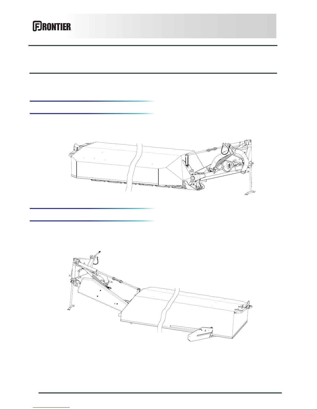
1. Front view
2. Rear view
Page 7
Identification of the machine
5
DM1160
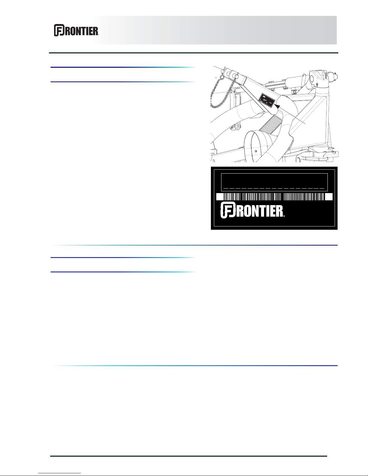
3. Model identification plate
Please write below the type and serial number of the
machine. This information is to be given to your John
Deere dealer for all parts order or warranty claim.
Type: DM1160
Serial no.:
4. Optional equipment
Check the boxes corresponding to th e equipment fitted
on your machine:
TYPE
MASSE kg
K
U
H
N
S
.A.
67
70
0
SAVERNE - F
R
ANCE
N°
M
A
D
E
IN
F
R
A
N
C
E
DEERE & COMPANY, MOLINE, ILLINOIS USA
MADE IN FRANCE
Kit no. KN1086060: PTO shaft with free wheel.
Kit no. KN1036040: "HD" disks.
Kit no. KN1016400: Raised skid shoes.
Kit no. KN1036010: 2 swath shields.
Kit no. KN1036000: Inner swath shield.
Page 8

6
Safety
DM1160
$SAFETY
1. Description of symbols used in this
document
This symbol indicates a potentially hazardous situation
that if not avoided, could result in serious bodily injury.
This symbol is used to identify special instructions or
procedures which, if not followed strictly, could result in
machinery damage.
This symbol is used to communicate technical
information of particular interest.
Page 9
Safety
7
DM1160
2. Safety instructions
Read and follow the safety instructions
Before using the machine, carefully read all the safety
instructions in this manual and the warnings placed on
the machine.
Before starting work, the operator must be familiar with
all machine controls, handling devices and their
functions. It is too late to learn once work has been
started!
Never let anyone operate the machine who is not trained
to do so.
Should you have any difficulties in understanding certain
parts in this manual, please contact your John Deere
dealer.
Precautions to be taken before carrying out
any operations on the machine
Before leaving the tractor or before adjusting,
maintaining or repairing the machine, disengage the
PTO drive, turn off the engine, r emove ignition key and
wait until all moving parts have come to a complete stop
and apply park brake.
Introduction
The machine must only be operated, maintained and repaired by qualified persons who are familiar with the
machines' operation and understand safety regulations and procedures for preventing accidents.
The operator must follow the safety instructions in this manual and in the warnings posted on the machine. The
operator is also obliged to respect current legislation concerning accident prevention, work safety and public
traffic circulation.
The intended use of the machine includes following all operation, maintenance and repair recommendations
given by the manufacturer, and using only genuin e spare par ts, equip men t and accessorie s, a s re co mmende d
by the manufacturer.
The manufacturer is not held liable for any damage resulting from machine applications other than those
specified by the manufacturer. Any use other than the designated operation is at the risk and responsibility of
the operator.
The manufacturer is not held liable for any damage or accident resulting from machine modifications carried out
by the operator himself or by a third party without previous written agreement from the manufacturer.
BEFORE ADJUSTING
MAINTAINING OR REPAIRING
THE MACHINE, TURN OFF THE
ENGINE, REMOVE IGNITION
KEY AND WAIT UNTIL ALL
MOVING PARTS HAVE COME TO
A COMPLETE STOP.
599 004 20
Page 10
8
Safety
DM1160
Precautions to take before using the
machine
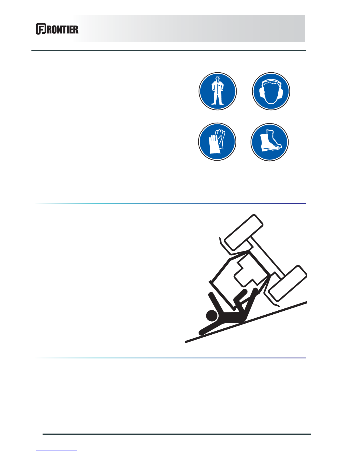
Do not wear loose clothing which could become caught
up in moving parts.
Wear appropriate protective clothing (gloves, shoes,
goggles, helmet, ear defenders, etc.).
Ensure that all operating controls (ropes, cables, rods,
etc) are placed so as they cannot be operated
unintentionally and cause damage or injury.
Before operating the machine, check tightness of nuts
and bolts, particularly on components that the machine
uses to process material (tines, forks, blades, knives,
etc). Retighten if necessary.
Before operating the machine, ensure that all the safety
guards are firmly in place and in good condition.
Immediately replace any worn or damaged guard.
Precautions when driving
Tractor handling, stability, performance and braking
efficiency are all affected by weight distribution, trailed or
mounted implements, additional ballast and driving
conditions. It is therefore of great importance that the
operator exercises caution in every given situation.
Drive speed must be adapted to ground conditions as
well as to roads and paths. Always avoid abrupt changes
of direction.
Be particularly cautious when turning corners, paying
attention to machine overhang, length, height and
weight.
Never use a narrow track tractor on very uneven or
steeply sloping ground.
Never leave the tractor seat while the machine is
operating.
Carrying people or animals on the machine when
working or in transport is strictly forbidden.
Page 11
Safety
9
DM1160
Precautions when driving on public roads
Dimensions
Depending on the dimensions of the machine, contact
the relevant authorities to ensure that it can be legally
transported on public roads.
If the machine is over the maximum legal size, follow the
local regulations for special transportation of oversize
equipment.
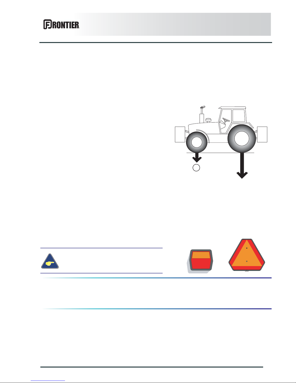
Gross weight and weight per axle
Check that the tractor's authorized gross weight as well
as its lift capacity and maximum weight per axle are not
exceeded.
The front axle load (1) must never, under any
circumstances, be less than 20% of the tractor's unladen
weight. If necessary, add ballast weights to the front or
to the rear to preserve the steering and braking
efficiency.
Transport position
Before transporting the machine on public roads, place
the machine into its transport position, according to the
instructions in this manual.
Lights and indicators
Before transporting the machine on public roads, ensur e
that all legally required lights and indicators are in place.
Ensure that lights and indicators are clean and in good
working order. Replace any missing or broken
equipment.
Maximum speed
Always keep to the legal speed limit for driving a tractormachine assembly on public roads.
Always obey current regulations for driving
on roads.
kg
lb
kg
lb
1
Page 12
10
Safety
DM1160
Precautions when coupling
Before attaching the machine, make sure that it cannot
accidentally start moving (chock the wheels) and that the
parking stand is in the right position.
The machine must only be attached to the hitch points
provided for this purpose.
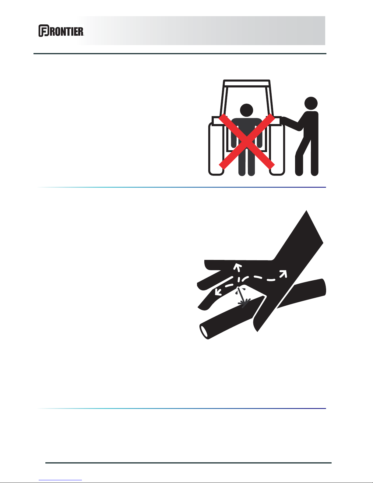
Never stand between the tractor and the machine when
operating the three point linkage.
Do not stand between the tractor and the machine
without ensuring that the parking brake is applied.
Hydraulic circuit
Caution! The hydraulic circuit is under high pressure.
Maximum pressure at work: 200 bar (2900 psi).
Before connecting hoses to the tractor hydraulics,
ensure that tractor and machine circuits are not under
pressure. Before disconnecting a hose, depressurize the
hydraulic circuit.
To avoid making incorrect connections, mark hydraulic
couplers and corresponding hoses with colors.
WARNING! Functions could be reversed (for example:
lift/lower) and cause accidents.
Regularly check the hydraulic hoses. In case of normal
wear, replace the hydraulic hoses every 5 years.
Damaged or worn hoses must immediately be replaced.
When replacing the hydraulic hoses, only use hoses with
the specification recommended by the manufacturer of
the machine.
To locate a leak, use appropriate means. Protect body
and hands from liquid under pressure.
Any liquid under pressure (particularly oil from
hydraulics) can penetrate the skin and cause severe
injury. If injured, see a doctor immediately, there could
be danger of infection.
Before any adjustments, maintenance or repairs are
carried out, lower the machine to the ground,
depressurize the hydraulics, turn off the engine, remove
ignition key and wait until all moving parts have come to
a complete stop.
Page 13
Safety
11
DM1160
PTO shaft
Do not wear loose clothing that could be caught in the
rotating PTO shaft.
Before attaching or removing a PTO shaft, or before
doing any work on the machine, disengage the PTO
drive, turn off the engine, remove ignition key and wait
for all moving parts have come to a complete stop.
If the primary PTO shaft is equipped with a torque limiter
or a free wheel, these must be fitted on the machine
side.
Ensure that the PTO shaft is always correctly fitted and
locked into place.
Before connecting the PTO shaft, ensure that the PTO
speed (rotational frequency) and direction of rotation are
in line with the machine manufacturer's
recommendations.
Before engaging the PTO drive, make sure all people
and animals are clear from the machine. Never engage
the PTO drive when the tractor engine is stopped.
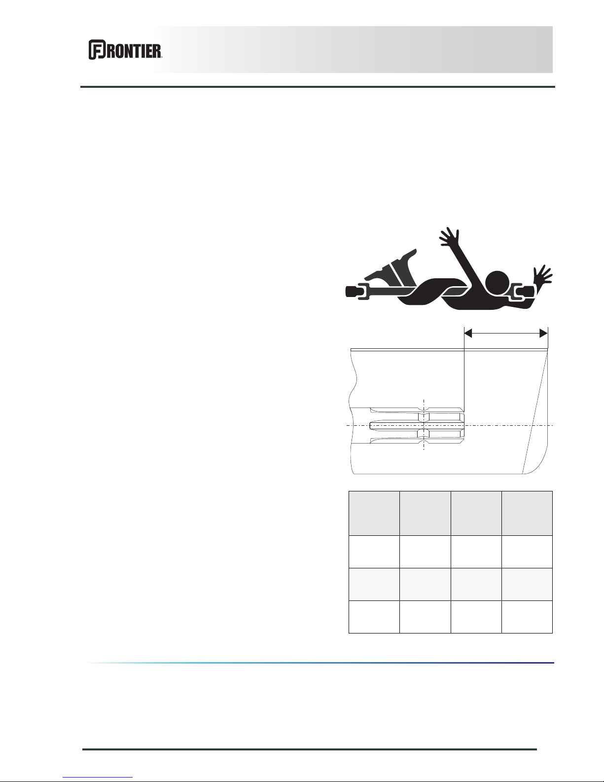
Do not install any adapter device that results in a portion
of the tractor PTO stub, the rotating PTO shaft, or the
adapter to be unguarded. The tractor master shield shall
overlap the end of the splined shaft and the added
adaptor device as outlined in the table.
When uncoupling the machine, rest the PTO shaft on the
support specially provided, and replace protective shield
on the PTO stub of the tractor.
Read and follow the instructions in the operator's manu al
provided with the PTO shaft.
Use only PTO shafts supplied with the machine or recommended by the machine manufacturer.
The protective shield of the tractor PTO stub, the PTO shaft guards and the protective shield of the machine
input shaft must always be in place and in good condition.
Make sure that the PTO shaft guards are secured with the safety chains provided. Check that the PTO shaft
guard can turn freely a full rotation independent of the shaft.
Any worn or damaged guards must be replaced immediately. A worn guard or an unprotected PTO shaft can
cause a serious or even a lethal accident.
A
PTO type Diameter X splines
A
±5 mm (0.20’’)
1
35 mm
(1.378’’)
6
85 mm
(3.35’’)
2
35 mm
(1.378’’)
21
85 mm
(3.35’’)
3
45 mm
(1.772’’)
20
100 mm
(4.00’’)
Page 14

12
Safety
DM1160
Precautions during maneuvers
When moving the machine from the transpor t position to
the working position and vice versa, make sure that
nobody is within the machine pivoting area.
Remote controlled components
Danger of crushing and shearing can exist when
components are operated by hydraulic or pneumatic
controls. Keep away from these danger zones.
Safety decals
Safety warnings are placed in safety decal form on
various parts of the machine. They are there to warn you
of potential dangers and to tell you how to avoid
accidents.
Always keep the safety decals clean and readable, and
replace them when they are worn, damaged, missing or
illegible.
Waste disposal
Respect the environment! Never spill pollutants (oil,
grease, filters, etc.) on the ground, never pour them
down the drain and never discard them in any other
place where they could pollute the environment. Never
throw away or burn a tire. Always take waste to
specialized recycling or waste disposal centers.
Page 15

Safety
13
DM1160
Precautions for maintenance and repair
work
Before leaving the tractor or before adjusting,
maintaining or repairing the machine, disengage the
PTO drive, turn off the engine, r emove ignition key and
wait until all moving parts have come to a complete stop
and apply park brake.
Rest the machine on the gr ound, release the pressure
from the hydraulic circuit and leave the machine to cool
down.
Make sure that the parts of the machine that need to be
lifted for maintenance or repair work are firmly propped
up.
Before any work is done on the e lectric circ uit or before
any electric welding is carried out on the attached
machine, disconnect the machine from the tractor
electrical circuit. Also disconnect alternator and battery
terminals.
Repairs on elements under pressure or te nsion (springs,
pressure accumulators, etc.) must only be carried out by
competent persons with regulation equipment.
Wear appropriate protective clothing (gloves, shoes,
goggles, helmet, ear defenders, etc.).
Do not solder, weld or use a blow torch near fluids under
pressure or flammable components.
For your own safety and for correct machine operation,
only use original manufacturer parts.
It is strongly recommended to have your machine
checked by your John Deere dealer after each season,
especially tools and their attaching hardware.
Page 16
14
Safety
DM1160
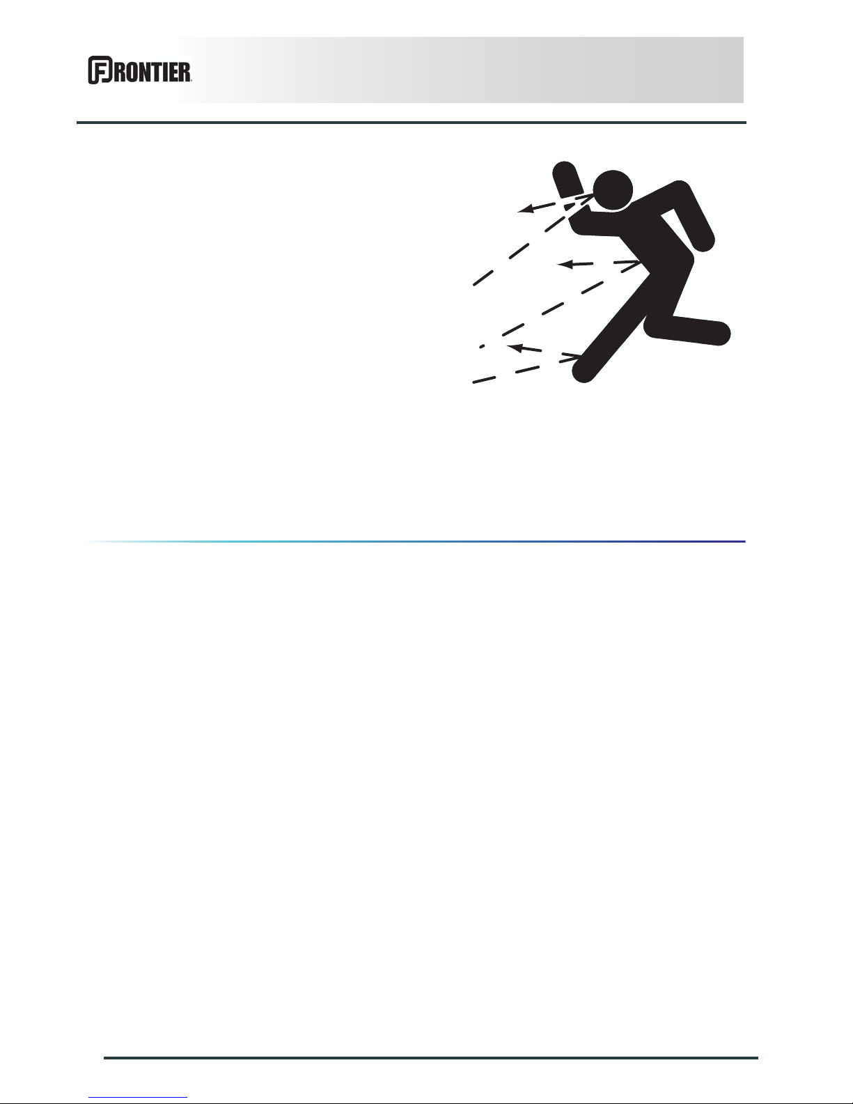
Projection of stones and foreign objects
For driver safety, always use a tractor equipped with a
cab. Keep the ground to mow free of foreign bodies.
Avoid mowing on stony or rocky grounds. If this is not
possible, take extra safety precautions, such as:
- Fit polycarbonate screens inside the tractor cab's side
and rear windows, or install narrow mesh guards on
their exterior.
- Increase the cutting height to avoid contact with
stones or rocks.
Never start the machine when there are people nearby.
Even when the machine is used properly, objects may be
thrown. Stones and other foreign objects thrown by the
moving parts can travel a considerable distance. Keep
all persons and animals away from the danger zone.
The protection covers help reducing risks of projections.
Therefore, make sure that all mower protection devices
are in place and good condition prior to using the
machine.
Regularly check the condition of the protection covers.
Immediatly replace any worn, damaged or missing
cover.
Page 17

Safety
15
DM1160
Precautions for machine use
After each use, check the cutting tools (disks, knives)
and their attachment hardware in accordance with the
instructions given in the present manual. Immediately
replace any worn, damaged or missing cutting tool or
element. To do this, use the tool outf it supplied with t he
machine. For your safety, only use genuine KUHN
parts !
Regularly check the condition of the protection covers.
Immediatly replace any worn, damaged or missing
cover. Before engaging the PTO, rest the cutterbar on
the ground. Make sure all the guards are in place. Keep
all persons and animals away from the danger zon e.
Stay a safe distance from the machine when the cutting
tools are in movement.
Never work in reverse.
After disengaging the PTO drive, cuttings tools can
continue rotating for some time. Stay away from the
machine until all moving parts have come to a complete
standstill.
If the machine hits an obstacle, disengage the PTO
drive, stop the tractor engine, remove the ignition key
and wait for all moving parts to come to a complete
standstill. Check the entire machine for any damage
before resuming work.
Page 18
16
Safety
DM1160
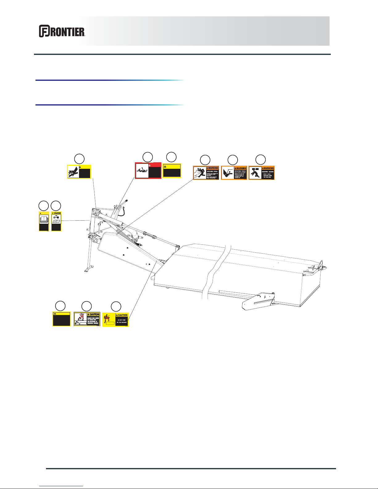
3. Location and description of safety
decals on the machine
Location of safety decals
BEFORE STARTING THE
MACHINE READ OPERATOR’S
MANUAL AND SAFETY
INSTRUCTIONS.
REQUEST COPY IF NOT
SUPPLIED.
CAUTION
BEFORE ADJUSTING
MAINTAINING OR REPAIRING
THE MACHINE, TURN OFF THE
ENGINE, REMOVE IGNITION
KEY AND WAIT UNTIL ALL
MOVING PARTS HAVE COME TO
A COMPLETE STOP.
599 004 20
1
2
3 4
5
6
7
DANGER
Avoid contact with
rotating parts
Entanglement in rotating
driveline can cause serious
injury or death
Keep all shields in place
099 262 10
099 257 10
Operate only with
540 rpm PTO
CAUTION
099 261 10
1. Keep all shields in place
2. Disengage and shut off al
engine and/or motor power
before servicing or unclog ging machine
3. Keep hands, feet and cloth ing away from power driven parts.
CAUTION
8
10
9
Avoid serious injury from injection of
pressurized hydraulic fluid.
Always relieve pressure before
performing service or maintenace
or any hydraulic components.
Refer to tractor and implement
Operator’s Manuals.
Do not use hand to search for leaks.
Use cardboard or similar material.
0992762
CAUTION
11
Page 19
Safety
17
DM1160
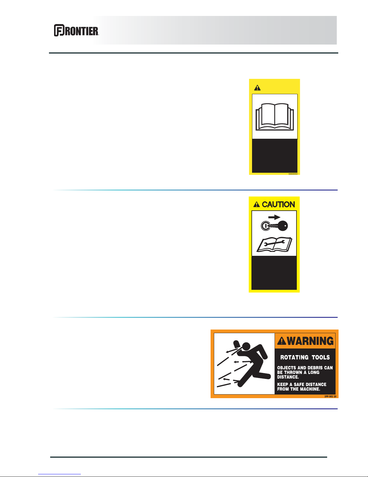
Description of safety decals
Operating instructions (1)
The operators' manual contains all the information
necessary for using the machine safely. It is imperative
to read and comply with all instructions.
Working on the machine (2)
Before leaving the tractor or before adjusting,
maintaining or repairing the machine, disengage the
PTO drive, turn off the engine, r emove ignition key and
wait until all moving parts have come to a complete stop
and apply park brake.
Projections (3)
Stones and other debris projected by the moving parts
can travel a long distance. The protection covers must
always be in position and in good condition. Always stay
at a safe distance from the machine.
BEFORE STARTING THE
MACHINE READ OPERATOR’S
MANUAL AND SAFETY
INSTRUCTIONS.
REQUEST COPY IF NOT
SUPPLIED.
CAUTION
BEFORE ADJUSTING
MAINTAINING OR REPAIRING
THE MACHINE, TURN OFF THE
ENGINE, REMOVE IGNITION
KEY AND WAIT UNTIL ALL
MOVING PARTS HAVE COME TO
A COMPLETE STOP.
599 004 20
Page 20
18
Safety
DM1160
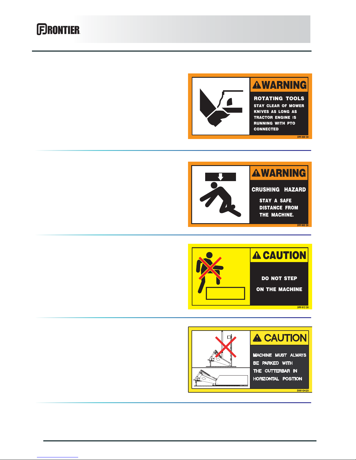
Rotating cutting tools (4)
Keep away from the mower knives all the time the engine
is running, the PTO drive engaged and the moving parts
have not come to a complete stop.
Body crushing (5)
Stay a safe distance from the machine.
Crushing hazard.
Do not step on the machine (6)
Do not step on the machine : Risk of falling or damaging
the protection device.
Uncoupling the machine (7)
Always park the machine with the cutterbar in horizontal
position.
Page 21
Safety
19
DM1160
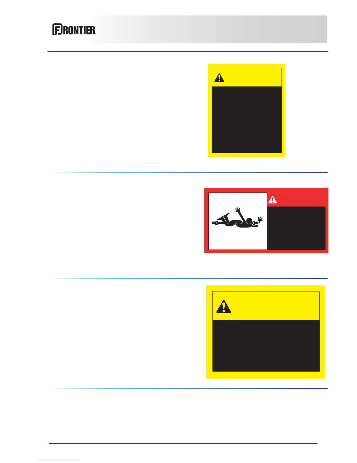
Precautions for machine use and
maintenance (8)
With the guards in position, disengage the PTO drive
and turn off the engine before adjusting, maintaining or
repairing the machine, keep at a safe distance from all
moving parts and wait until they have come to a
complete stop.
PTO shaft (9)
To prevent accidents, check that PTO shaft guards are
in place and stay at a safe distance from rotating parts.
PTO speed (10)
Never operate the machine at a PTO speed higher than
540 min
-1
.
099 261 10
1. Keep all shields in place
2. Disengage and shut off al
engine and/or motor power
before servicing or unclog ging machine
3. Keep hands, feet and cloth ing away from power driven parts.
CAUTION
DANGER
Avoid contact with
rotating parts
Entanglement in rotating
driveline can cause serious
injury or death
Keep all shields in place
099 262 10
099 257 10
Operate only with
540 rpm PTO
CAUTION
Page 22
20
Safety
DM1160
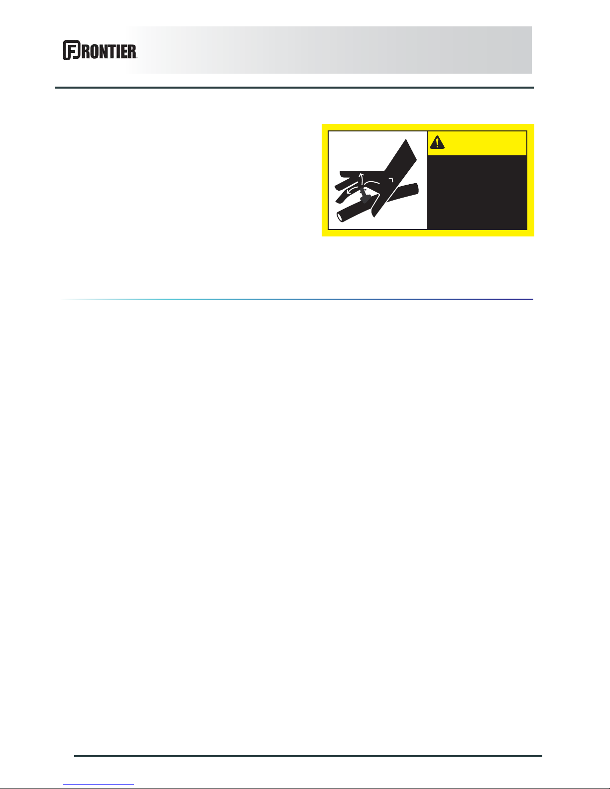
Hydraulic circuit under pressure (11)
Any liquid under pressure (particularly oil from
hydraulics) can penetrate the skin and cause severe
injury.
Before any adjustments, maintenance or repairs are
carried out on the hydraulic circuit, always relieve
pressure and comply with instructions given in the
tractor and machine operator's manuals.
To locate a leak, protect body and hands from liquid
under pressure and use appropriate means : cardboard
or similar material.
Avoid serious injury from injection of
pressurized hydraulic fluid.
Always relieve pressure before
performing service or maintenace
or any hydraulic components.
Refer to tractor and implement
Operator’s Manuals.
Do not use hand to search for leaks.
Use cardboard or similar material.
0992762
CAUTION
Page 23
Machine specifications
21
DM1160
$MACHINE SPECIFICATIONS
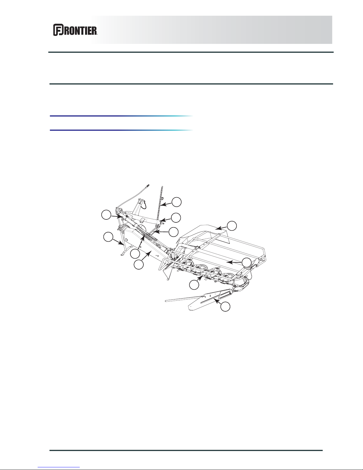
1. Description and glossary
0
1 : Check chain 2 : Three-point hitch coupler
3 : Safety breakback 4 : Parking stand
5 : Work/transport cylinder 6 : Compensating spring
7 : Belt guard 8 : Front guard
9 : Cutterbar 10 : Swath shield
10
9
7
4
3
4
5
6
1
2
8
Page 24

22
Machine specifications
DM1160
2. Technical specifications
3. Sound levels
Attachment type 3 point linkage category 1 and 2
Number of disks 6
Working width 2.40 m (7’10’’)
Width in working position 4.30 m (14’1’’)
Height in working position 1.15 m (3’9’’)
Length in working position 2.35 m (7’9’’)
Width in transport position 1.72 m (5’8’’)
Height in transport position 2.95 m (9’8’’)
Length in transport position 2.00 m (6’7’’)
Disk rotational speed 3030 min
-1
PTO speed 540 min
-1
Weight 452 kg (996 lb)
Minimum PTO power requirement 31 kW (42 hp)
Sound levels have been measured in accordance with the measuring methods as defined in:
NF EN ISO 4254-1
«Agricultural machinery - Safety - Part 1: General requirements»
Weighted equivalent continuous acoustic pressure level at the driver's seat (closed cabin) L (A) eq:
Tractor only: 79.3 dB(A)
Tractor + machine: 81.5 dB(A)
Page 25
Putting into service
23
DM1160
$PUTTING INTO SERVICE
1. Description of control elements
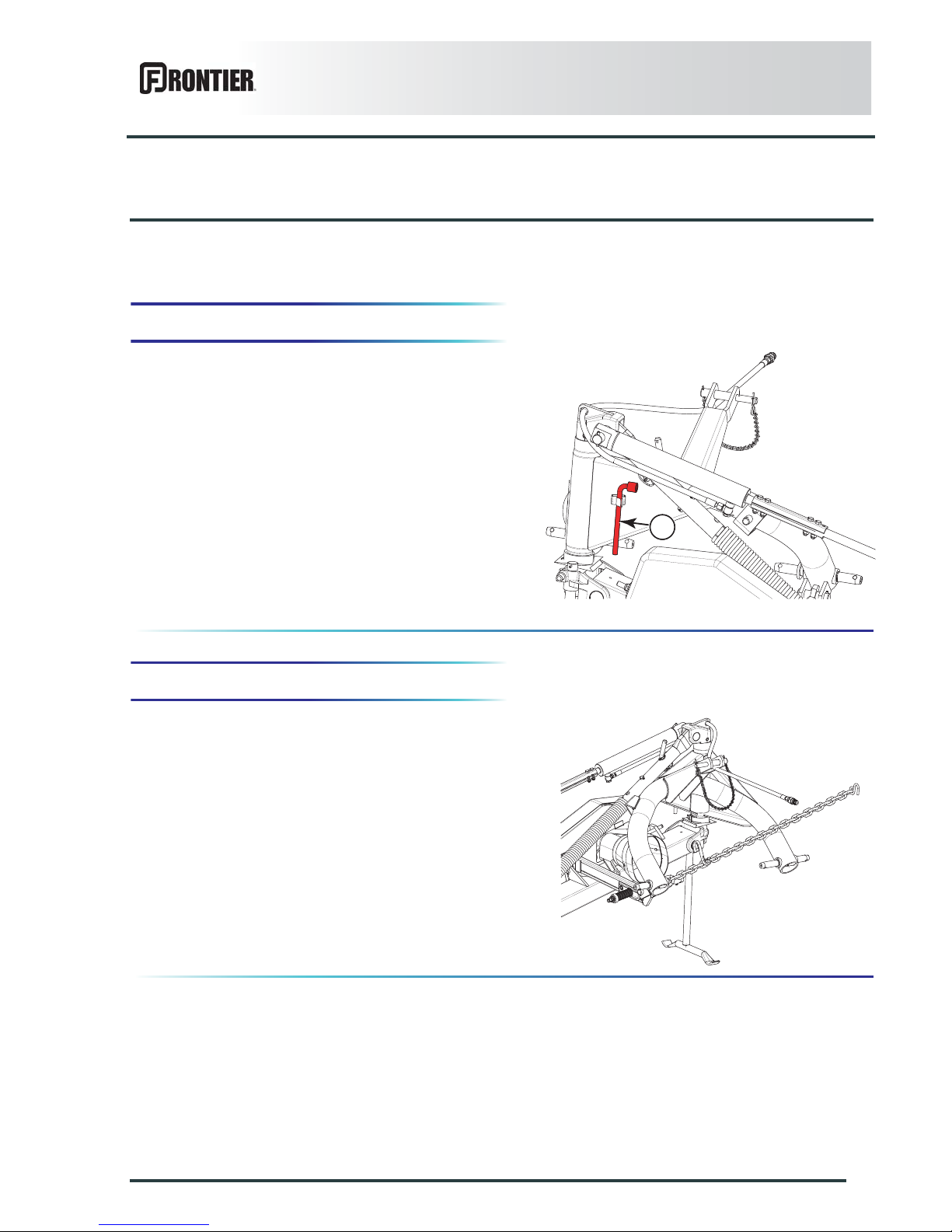
The machine is supplied with an 16 mm box wrench (1)
to carry out certain adjustment and maintenance tasks.
2. Coupling and uncoupling
The machine adapts to tractors fitted with a 3-point hitch
coupler category 1 or 2.
Description of coupling elements
- A PTO shaft 1 3/8’’ - 6 splines.
- A check chain.
- One hydraulic hose which controls the machine
transport/work position setting.
1
Page 26
24
Putting into service
DM1160
Preparing the tractor
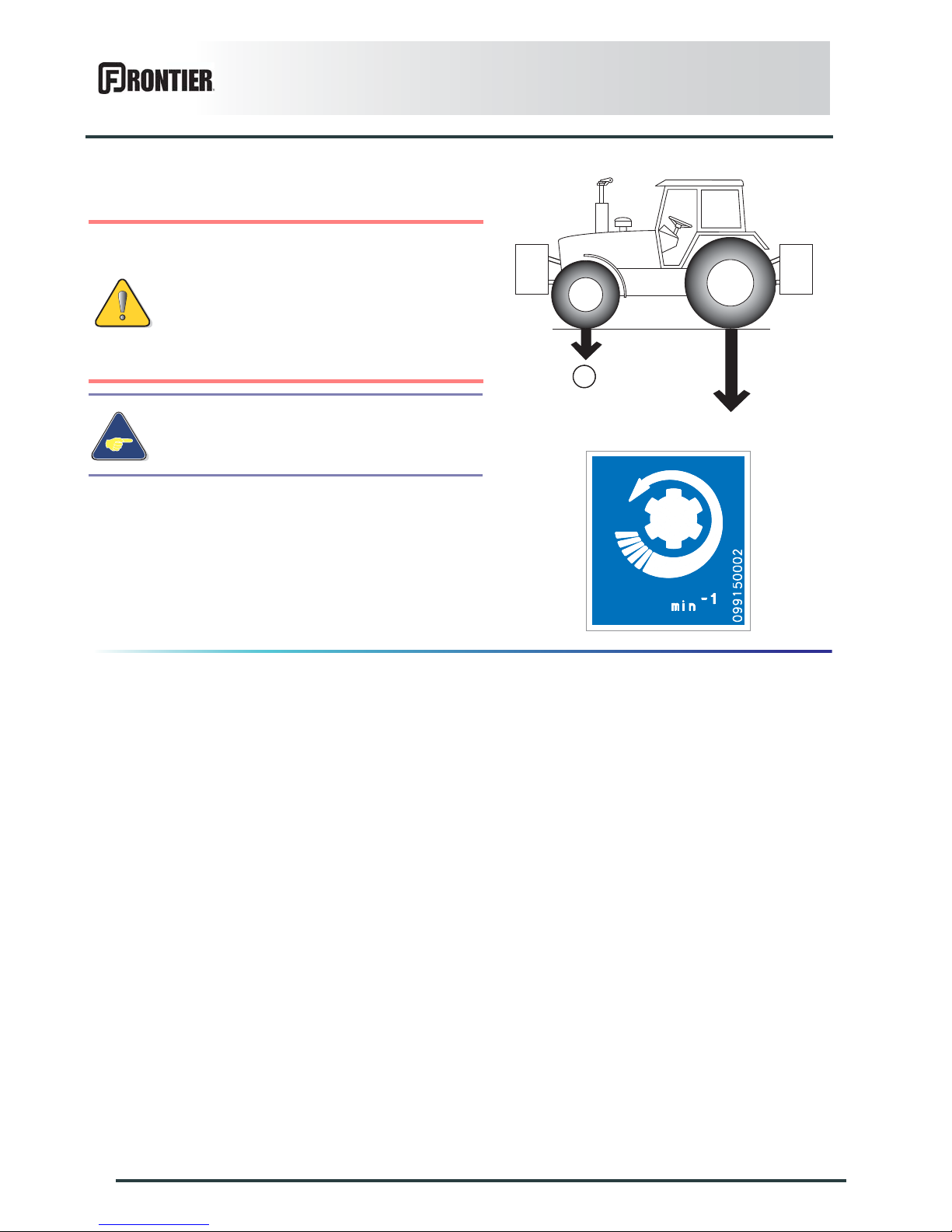
The tractor PTO stub must rotate at a speed of 540 min-1.
The tractor must be equipped with a single-acting
hydraulic outlet.
Check that the tractor's authorized gross
weight as well as its lift capacity and
maximum weight per axle are not exceeded.
The front axle load (1) must never, under any
circumstances, be less than 20% of the
tractor's unladen weight. If necessary, add
ballast weights to the front or to the rear to
preserve the steering and braking efficiency.
The tractor must be fitted with lower link
stabilizers.
kg
lb
kg
lb
1
540
Page 27
Putting into service
25
DM1160
Preparing the machine
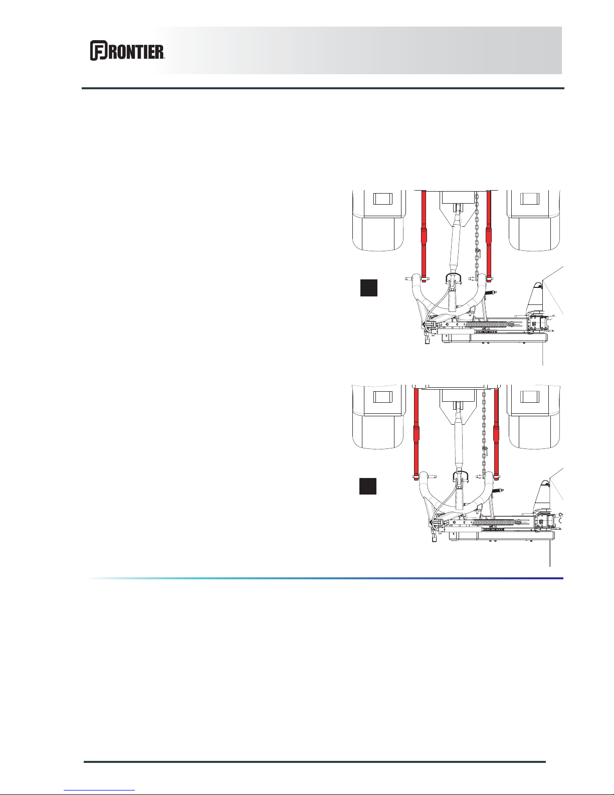
Linkage adjustment
The machine adapts to tractors fitted with a 3-point hitch
coupler category 1 or 2.
3 point, Category 1:
- Place lower links in position (a):
3 point, Category 2:
- Place lower links in position (b):
a
b
Page 28
26
Putting into service
DM1160
Coupling the machine
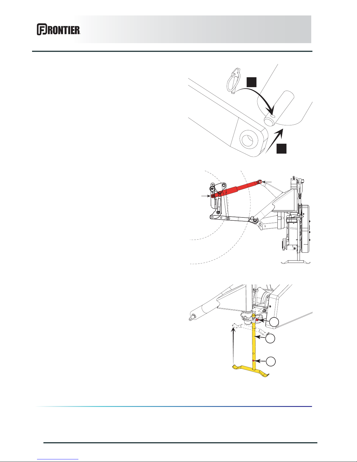
- Lower the tractor three-point linkage.
- Attach lower links to the hitch pins on either sides of
the machine (a).
- Secure each hitch pin with lynch pin (b).
- Attach top link.
- Lift the machine using the tractor lift linkage until the
parking stand no longer rests on the ground.
- Press push-button (1) and retract parking stand (2)
until push-button engages in position (3).
a
b
1
2
3
Page 29
Putting into service
27
DM1160
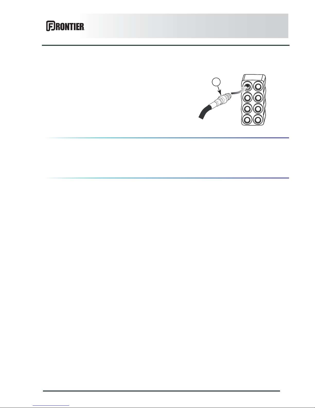
Hydraulic connections
-
- Connect the mowing unit lift cylinder to a single acting
valve.
Check chain
- Fit check chains
See section "Frame height adjustment" to position the
check chains.
1
Page 30
28
Putting into service
DM1160
Primary PTO shaft
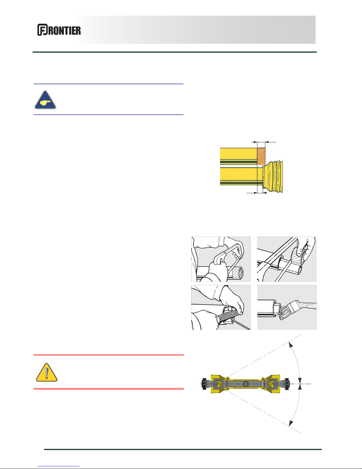
The tractor PTO stub must rotate at a speed of 540 min-1.
Separate the two half PTO shafts and connect them to
the machine's input shaft and to the tractor PTO stub.
Check the length of the PTO shaft:
- When the PTO shaft is in its maximum overlap
position (retracted), tubes should not butt against the
yokes. As a safety measure, a clearance (L) of at least
25 mm (1’’) must be maintained.
- When the PTO shaft is in its maximum extended
position, the tube overlap must be more than
250 mm (10’’).
If this is not the case:
• Mark length (H) to cut when the transmission is the
maximum overlap position.
• Shorten the guard tubes and the transmission tubes
by the same length.
• Bevel and clean the tubes.
• Grease the inside of the outer tube.
Never operate the PTO shaft at an angle X exceeding
30°.
Make sure that the PTO shaft is correctly
adjusted, to avoid premature wear and tear.
To avoid serious accidents, the PTO drive
shaft guards must be properly in place and
fixed with the chains provided.
H
L
X
X
Page 31
Putting into service
29
DM1160
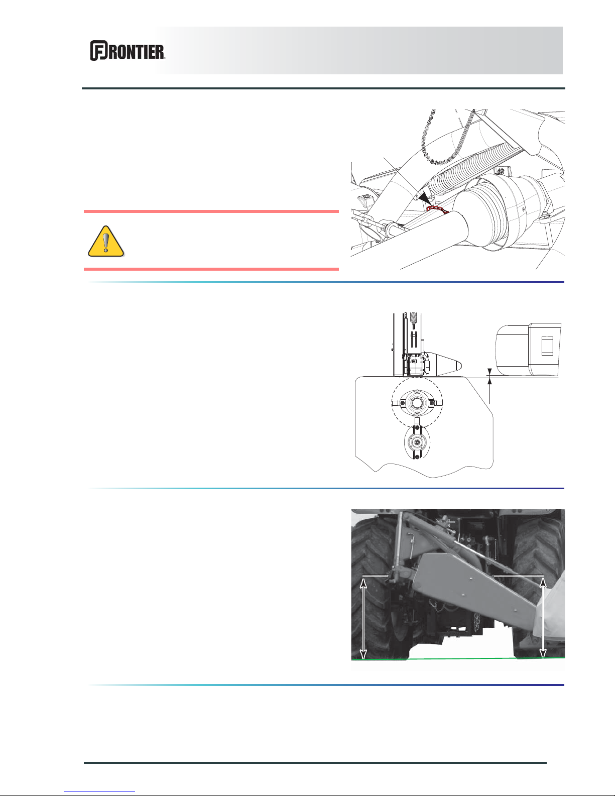
-
- Attach PTO shaft guard using chain provided in order
to prevent it from rotating.
Adjusting the machine
Positioning of lower links
- Measure dimension A.
- Adjust tractor lower link stabilizers to measure A =
50 mm (2’’).
Hitch pin parallelism.
From the headland turn position:
Measure and adjust the height of the hitch pins until the
same measure is obtained on each side:
- Note the difference in height between the two hitch
pins.
- Place the machine in working position:
- Adjust the tractor left levelling rod according to the
difference in height.
- Place the machine in headland turn position.
- Check the difference in height between the 2 hitch
pins.
- Proceed the same way to obtain identical (A) and (B)
heights.
Immediately replace any worn or damaged
guard.
A
A B
Page 32
30
Putting into service
DM1160
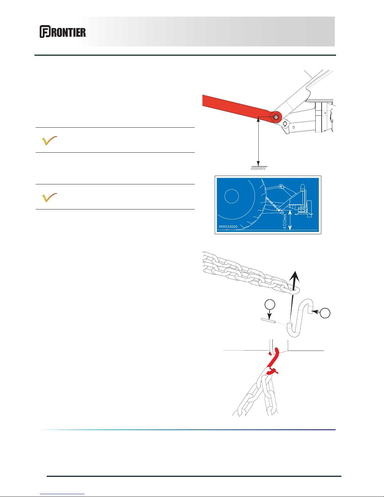
Frame height and check chains.
- Tractor fitted with a hydraulic position control function:
• Lower the tractor lift linkage so that hitch pins are at
a distance H = 400 mm (1’4’’) from the ground.
• Note the corresponding lever position in the tractor
cab.
Tractor not fitted with a hydraulic position control
function:
• Lower tractor lift linkage until hitch pins are at a
distance (H) slightly over H = 400 mm (1’4’’) from
the ground.
• Insert hook (1) in check chain link corresponding to
the required frame height and lock using roll pin (2).
• Attach each check chain with its hook supplied with
the machine to one of the upper fr ee holes at the
tractor's top link attachment clevis.
• Lower the machine until the check chain is under
tension.
The tractor lift linkage is in working position.
The height is correct when:
• The cutterbar is resting on the ground.
• The check chain is under tension.
• The distance H = 400 mm (1’4’’).
• The 2 hitch pins are parallel to the ground.
It is not necessary to use the check chain
supplied with the machine.
Refer to the decal fitted on the machine to check
the distance between the hitch pins and the
ground.
H
1
2
Page 33
Putting into service
31
DM1160
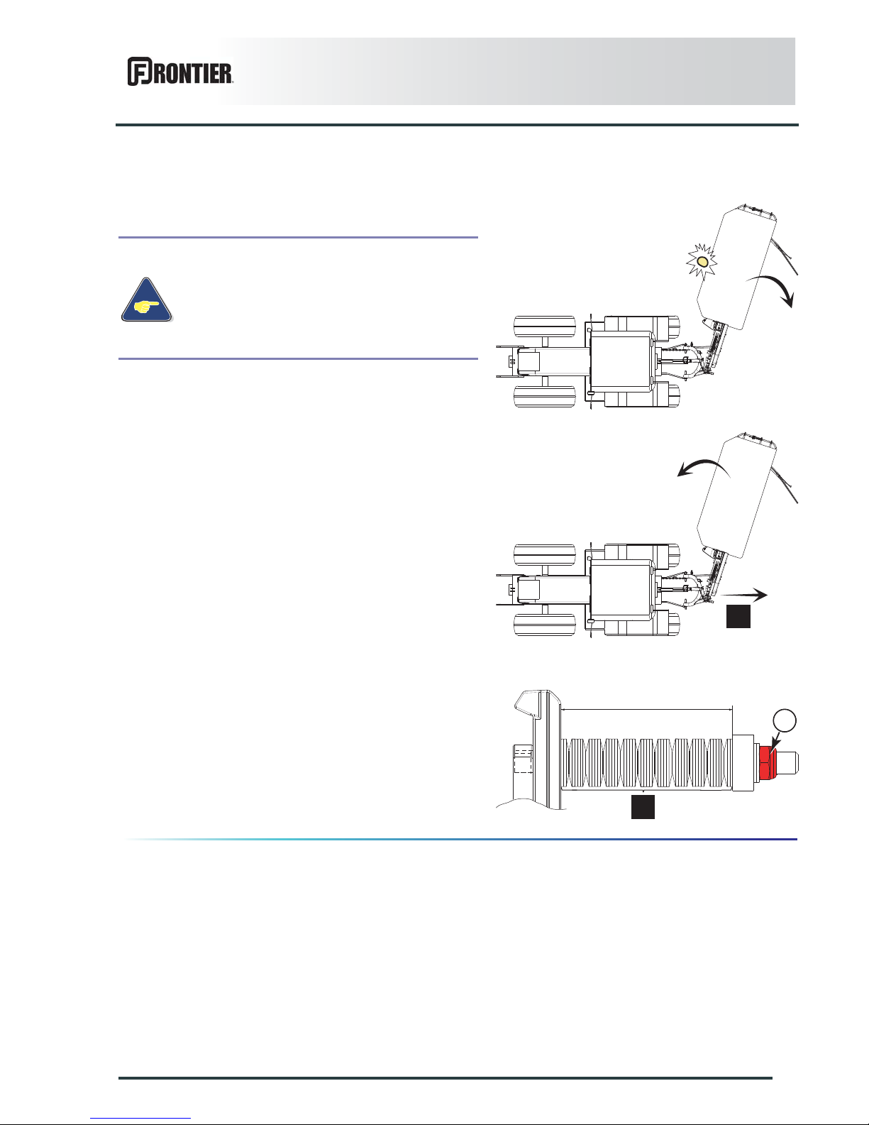
Safety breakback
On hitting an obstacle, the safety breakback causes the
cutterbar to pivot rearwards.
The safety breakback is reset by reversing (a).
If the safety breakback releases after reset, tighten
screw (1) to increase spring washer compression.
Basic adjustments:
L= 96 mm (3.8’’)
A= 20 times 2 washers.
If the machine hits an obstacle, disengage
the PTO drive, stop the tractor engine,
remove the ignition key and wait for all
moving parts to come to a complete
standstill.
In case an obstacle has been struck, check
that the mowing unit has not been damaged.
a
L
1
a
Page 34
32
Putting into service
DM1160
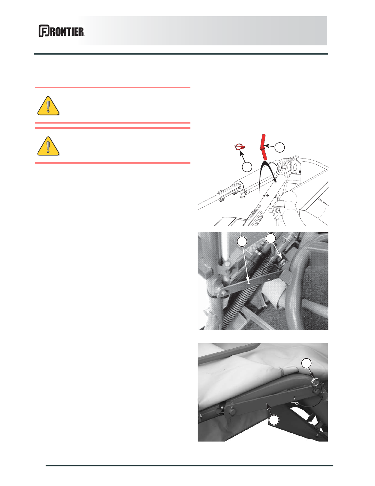
Uncoupling the machine
From the transport position:
- Remove lynch pin (1) and pin (2).
- Put compensation system in working position using
pin (2) and lynch pin (1).
- Remove R-clip (2).
- Remove transport lock (1).
- Install lock (1) on frame.
- Secure using R-clip (2).
For tractors not fitted with a hydraulic
position control function, unhook check
chain.
The machine must be uncoupled in working
position.
1
2
1
2
1
2
Page 35
Putting into service
33
DM1160
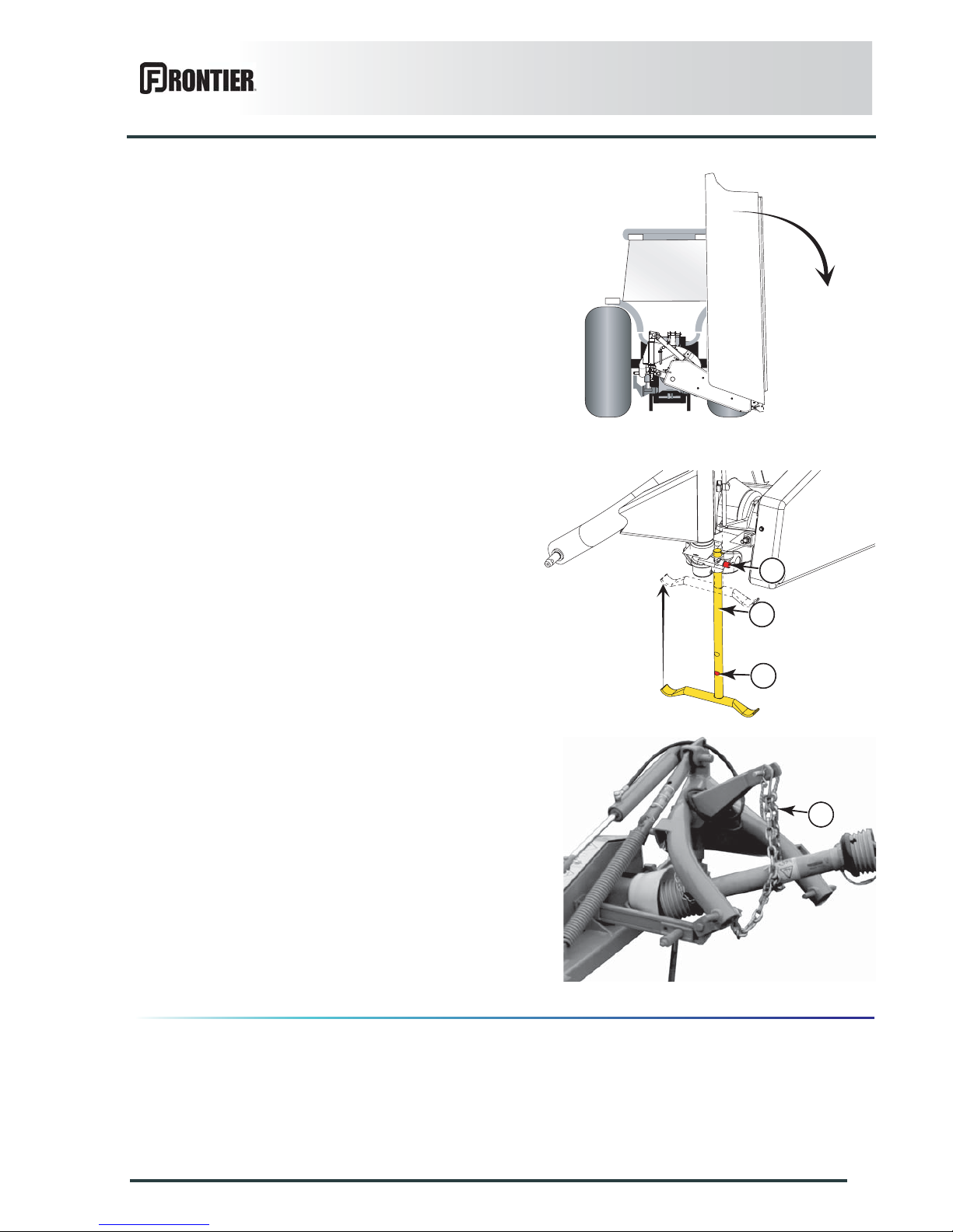
- Activate the transport/work cylinder control valve in
the "pivot into work" position.
- Lift the machine with the tractor's three point linkage.
- Press push-button (1) and lower parking stand (2)
until push-button engages in position (3).
- Lower the tractor three-point linkage to rest the
machine on the ground.
- Detach the top link from the machine end.
- Uncouple the primary PTO shaft.
- Support PTO shaft with check chain attached around
the hitch pin (1).
- Disconnect hydraulic hose from tractor.
- Release the lower links.
- Lower the tractor three-point linkage.
The machine is uncoupled.
1
2
3
1
Page 36
34
Instructions for transport
DM1160
$INSTRUCTIONS FOR TRANSPORT
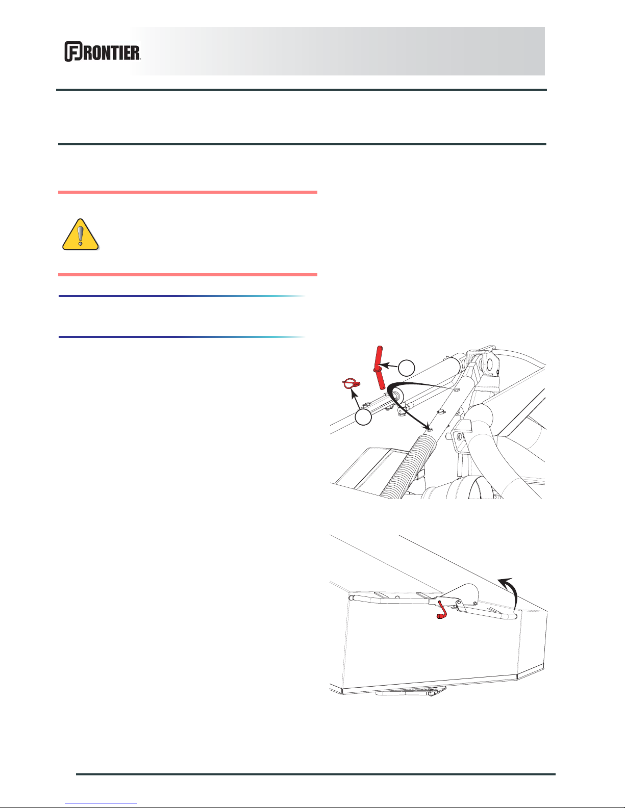
1. Putting the machine into transport
position
From the working position:
- Lift the machine with the tractor's three point linkage.
- Remove lynch pin (1) and pin (2).
- Lock compensation system in transport position using
pin (2) and lynch pin (1).
- Unlock and lift front guard using 16mm box spanner
supplied with the machine.
- The guard locks automatically.
Before placing the machine into transport
position:
- Check that nobody is within the machine
pivoting area.
- If there is someone, make sure the
person moves away.
1
2
Page 37
Instructions for transport
35
DM1160
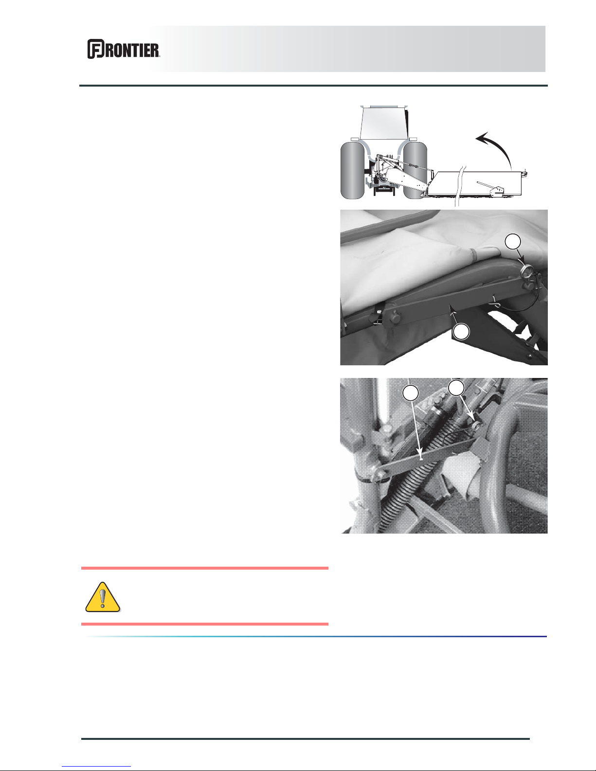
- Activate the transport/work cylinder to bring the
mowing unit in transport position.
- Remove R-clip (2).
- Remove transport lock (1).
- Install transport lock (1).
- Secure using R-clip (2).
The machine is in transport position.
Never engage the tractor PTO drive when the
machine is in transport position.
1
2
1
2
Page 38

36
Instructions for transport
DM1160
2. Conformity with the road regulations
Check that the retroreflective signalling equipment is
clean before going on public roads.
Before driving the machine on p ublic roads,
ensure that the machine complies with
current highway code regulations.
Replace worn or damaged reflectors.
Page 39
Instructions for work
37
DM1160
$INSTRUCTIONS FOR WORK
1. Putting the machine into work
position
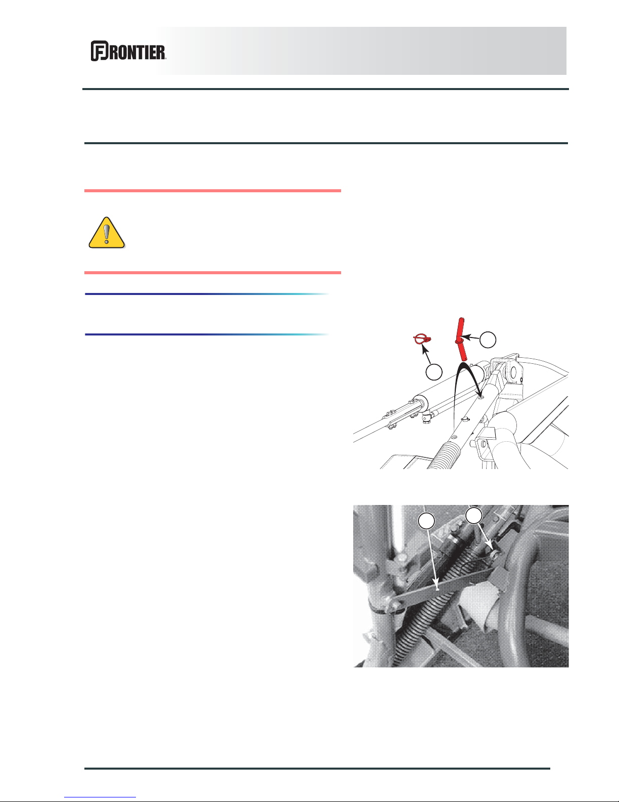
From the transport position:
- Lift the machine with the tractor's three point linkage.
- Remove lynch pin (1) and pin (2).
- Put compensation system in working position using
pin (2) and lynch pin (1).
- Remove R-clip (2).
- Remove transport lock (1).
Before placing the machine in working
position:
- Check that nobody is within the machine
pivoting area.
- If there is someone, make sure the
person moves away.
1
2
1
2
Page 40
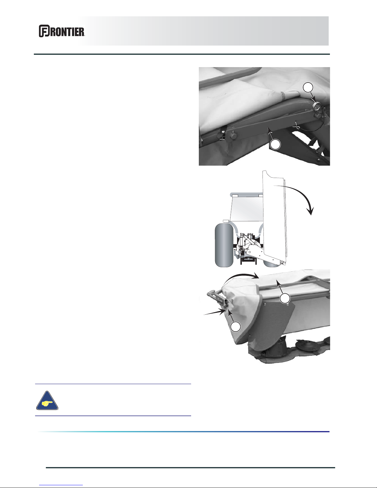
38
Instructions for work
DM1160
- Install lock (1) on frame.
- Secure using R-clip (2).
- Activate the transport/work cylinder control valve in
the "pivot into work" position.
- Press lock (1) and lower front guard (2).
- The guard locks automatically.
The machine is in working position.
During work, only use the tractor lift linkage
to place the machine in headland turn
position.
1
2
1
2
Page 41
Instructions for work
39
DM1160
2. Adjustments in working position
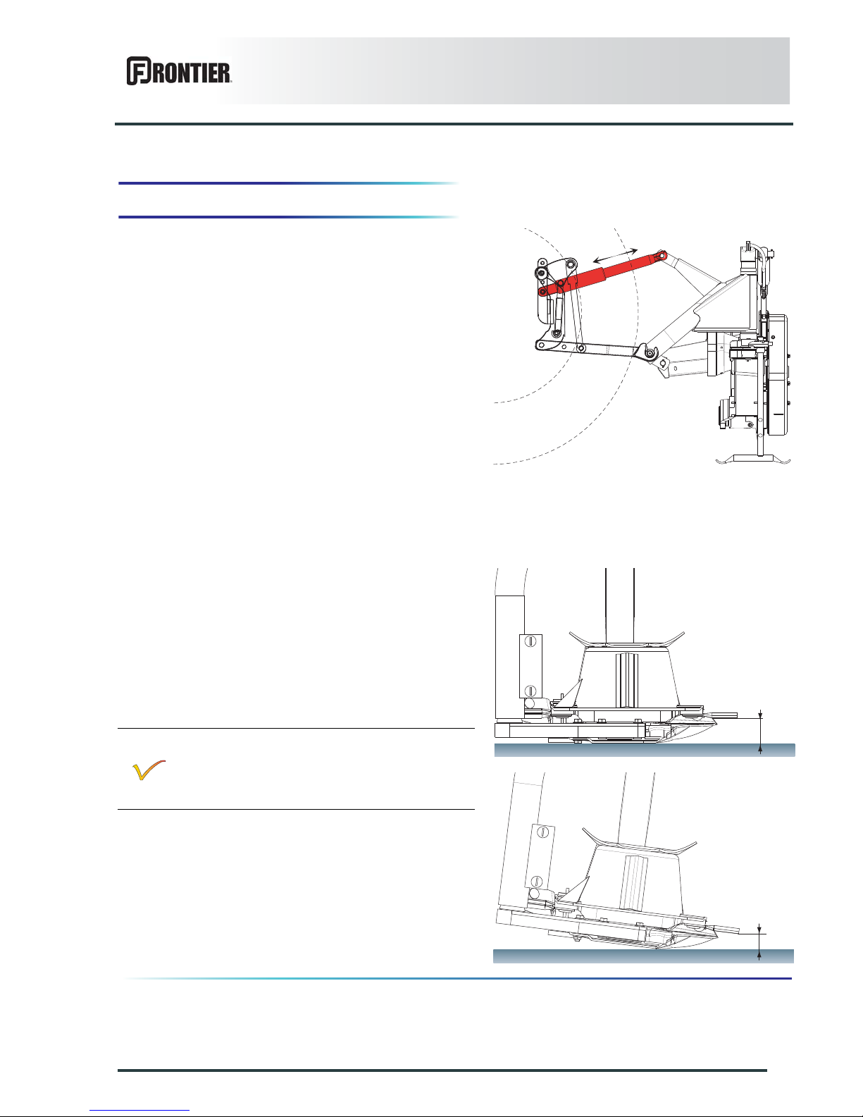
Cutting height
The desired cutting height is obtained directly by
adjusting the top link length. The height can be adjusted
between 30 and 80 mm (1.1’’ - 3.1’’) depending on the
tractors.
To obtain a different cutting height:
- Place the machine in working position.
- Lower the machine on the ground to remove weight
from the top link.
- Modify the top link length to alter the machine tilt
angle.
- Place the machine in working position to check cutting
height.
-
Too low a cutting height can lead to:
Excessive disk and knife wear.
Crop being contaminated by soil.
Delay in regrowth.
L1
L2
Page 42
40
Instructions for work
DM1160
Swathing system
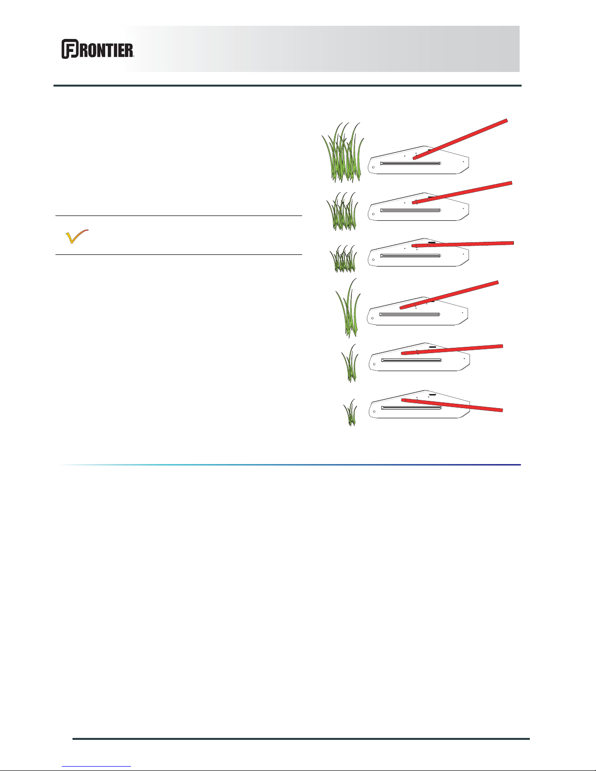
The swathing system comprises:
- A swath shield.
- A swath stick.
The swath stick fitted on the swath shield can be
adjusted in 6 positions according to the working
conditions:
Adjust stick angle according to the crop density
and length.
Page 43
Instructions for work
41
DM1160
On slopes
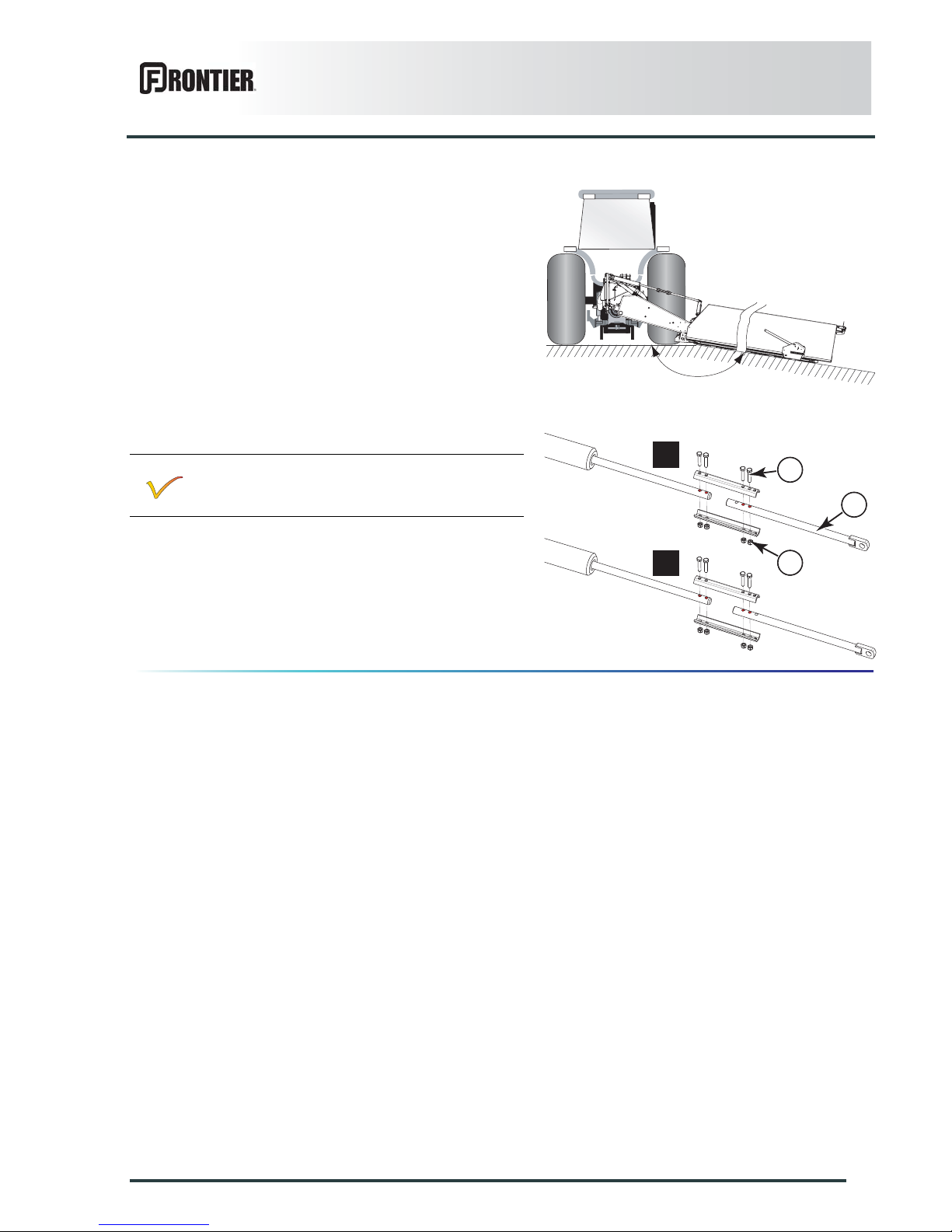
For mowing on slopes exceeding 10° below horizontal,
lengthen cylinder rod.
To switch from configuration (a) to configuration (b):
- Remove bolts (1) and nuts (2).
- Offset rod (3) to the required position.
- Reinstall bolts (1) and nuts (2).
- Tightening torque: 4.9 daN m (36 lbf ft).
Coupling device (a):Work on flat grounds.
Coupling device (b):On slopes (X).
X
2
3
1
a
b
Page 44
42
Instructions for work
DM1160
3. Machine use
Before the machine engages the crop:
- Engage the tractor PTO and slowly increase the
speed up to 540 min
-1
.
During work, only use the tractor lift linkage to place the
machine in headland turn position.
Drive speed
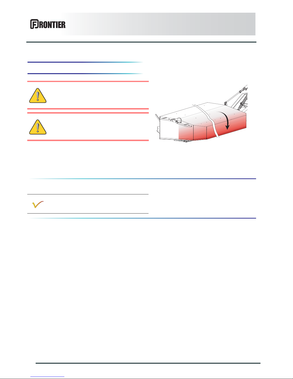
Before mowing and to reduce risks of
projections, lower the front guard.
Keep all persons and animals away from the
machine danger zone.
Never lean or step on the protection cover.
Adapt the forward speed to the working
conditions.
Page 45
Optional equipment
43
DM1160
$OPTIONAL EQUIPMENT
1. Reinforced PTO shaft
Part no. KN1086060
In the following cases, the machine can be fitted with a
longer, reinforced PTO shaft with a free wheel
- Too short standard PTO shaft.
- Tractor fitted with a hydraulic PTO.
- PTO shaft angle exceeds X = 25 degrees at work.
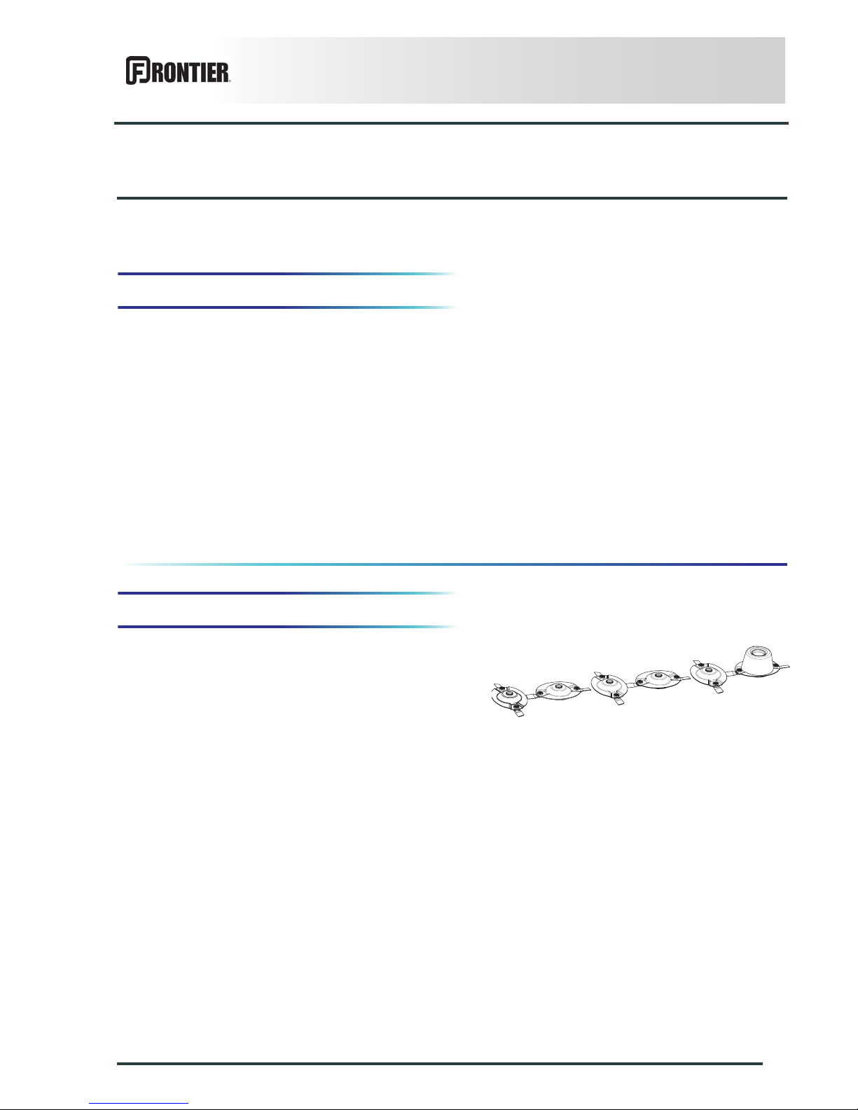
2. "HD" disks
Part no. KN1036040
The machine can be fitted with heavy disks and
reinforced knives to work in extreme conditions.
Page 46
44
Optional equipment
DM1160
Inspection of knives and securing elements
Knives
Inspect systematically all knives before the machine is
operated to:
• guarantee the cutting quality.
• guarantee safety in use.
• Prevent cutterbar damage risks.
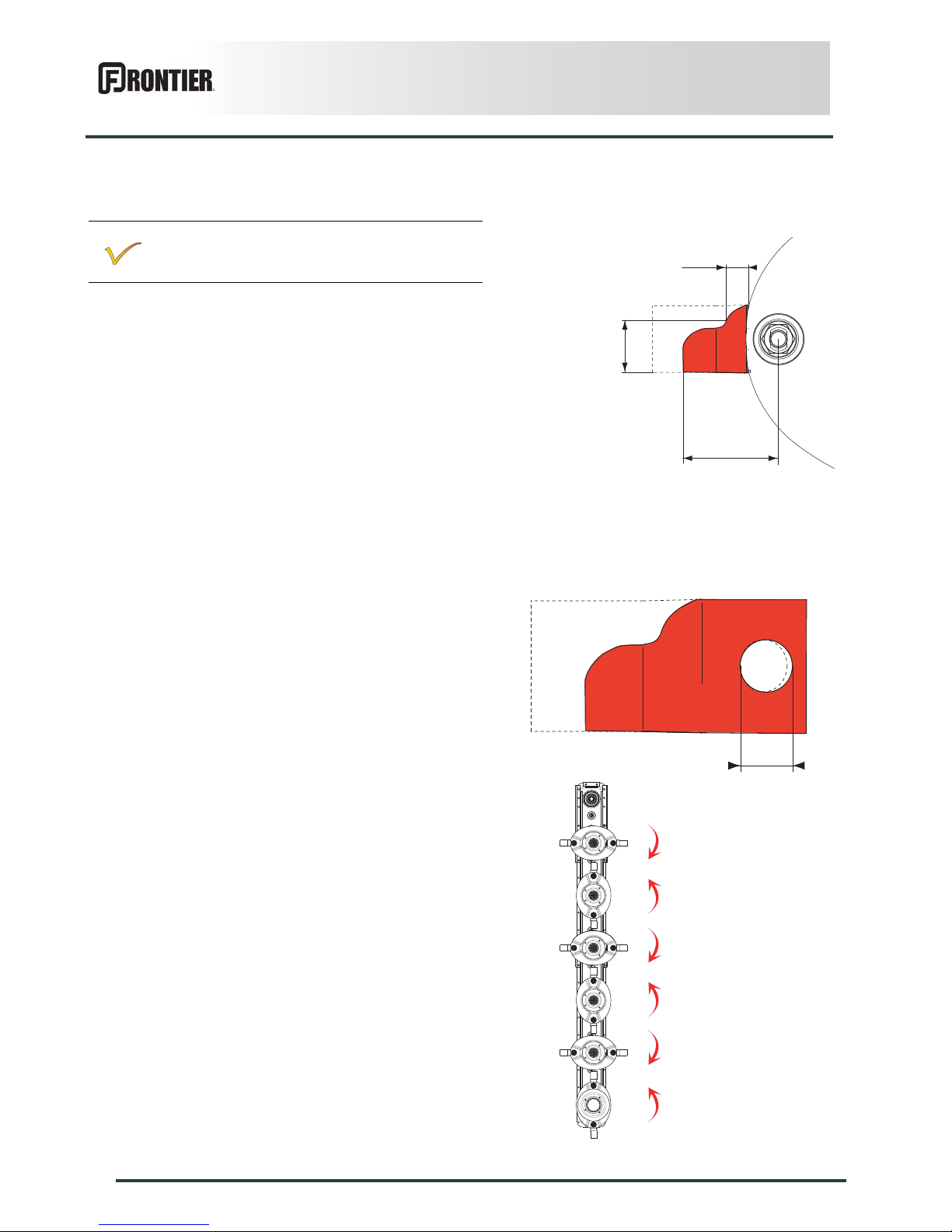
Replace knives in the following cases:
- Damaged knives. Very rough conditions can cause
knives to crack and become deformed.
- Worn knives
Knife length C must exceed 80 mm (3.15’’).
Knife width B, measured at a distance A of 10 mm (0.4’’)
from the disk edge must exceed 20 mm (0.8’’).
The hole L for the securing bolt must not become oval by
more than 20 mm (0.8’’).
Always replace both knives per disk to avoid creating an
out-of-balance force.
Immediately replace worn or damaged parts with
original manufacturer parts.
A
B
C
L
Page 47
Optional equipment
45
DM1160
Fixing elements
Check the fixing elements:
- After hitting an obstacle.
- When replacing knives.
- At the beginning of each season.
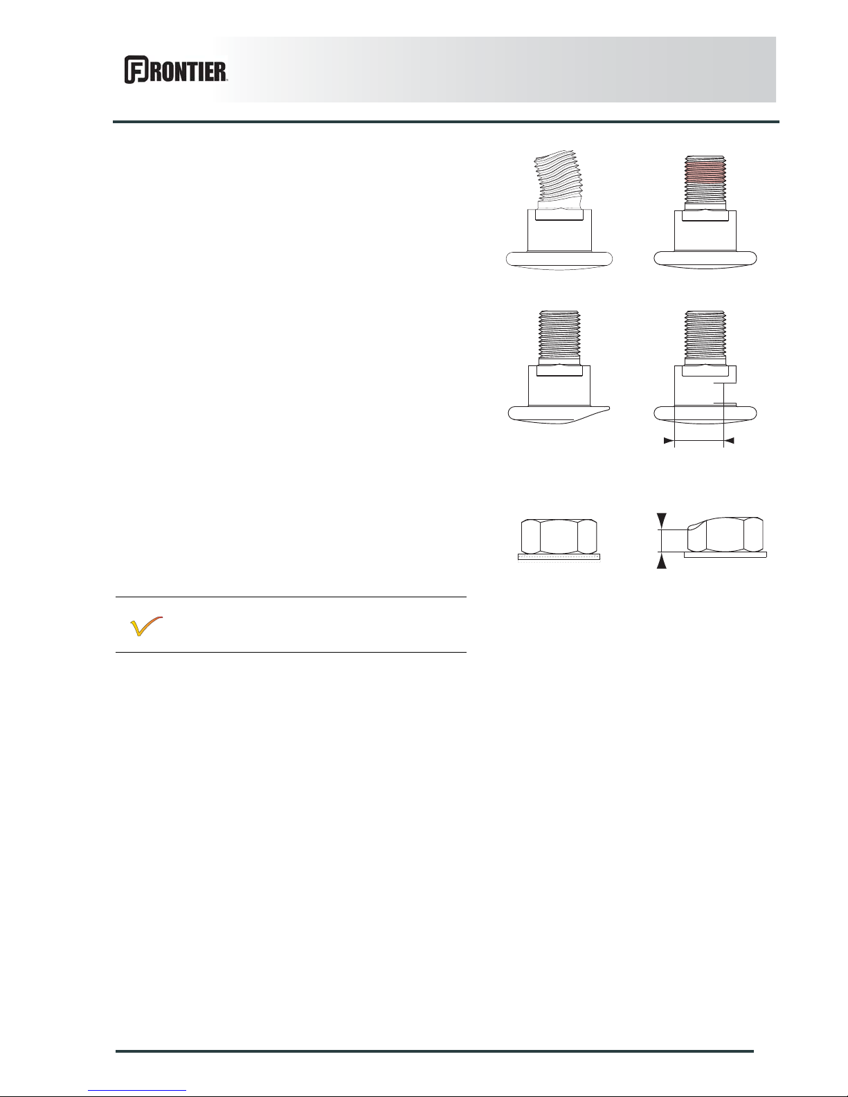
The fixing bolts should be changed in the following
cases:
- When there is visible distortion.
- When the locking compound is worn or inoperational.
- When the bolt head wear reaches the center line of
the bolt.
- When diameter D of the bolt shoulder is less than
15 mm (0.6’’).
- After having been removed 5 times.
Replace nuts in the following cases:
- When the contact washer has lost its elasticity.
- When the contact washer loosens itself from the nut.
- When nut wear reaches a = 5 mm (0.2’’).
- After having been removed 5 times.
-
Check the condition of the fixing elements
regularly and also the torque of the knife-fixing
bolt: 12 daN m (89 lbf ft).
D
a
Page 48
46
Optional equipment
DM1160
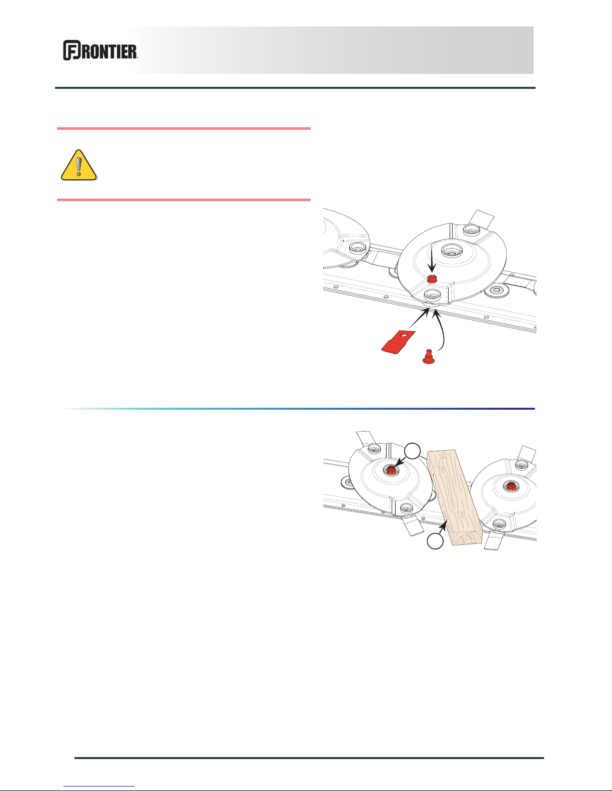
Knife replacement
Clean the nut case.
Place a wooden wedge between two disks to stop them
from rotating.
Loosen nut using box wrench supplied with the machine.
Remove bolt through opening located at the front of the
disk guard.
Knives can be turned over on the same disk to use the
other cutting edge or replaced. On each knife, an arrow
indicates the disk's direction of rotation.
Make sure that the securing nut and bolt are in good
condition and if necessary, replace them.
Torque knife locknut to 7.5 daN m (55 lbf ft).
Dull knives require more horse power and have a
negative effect on the cut quality.
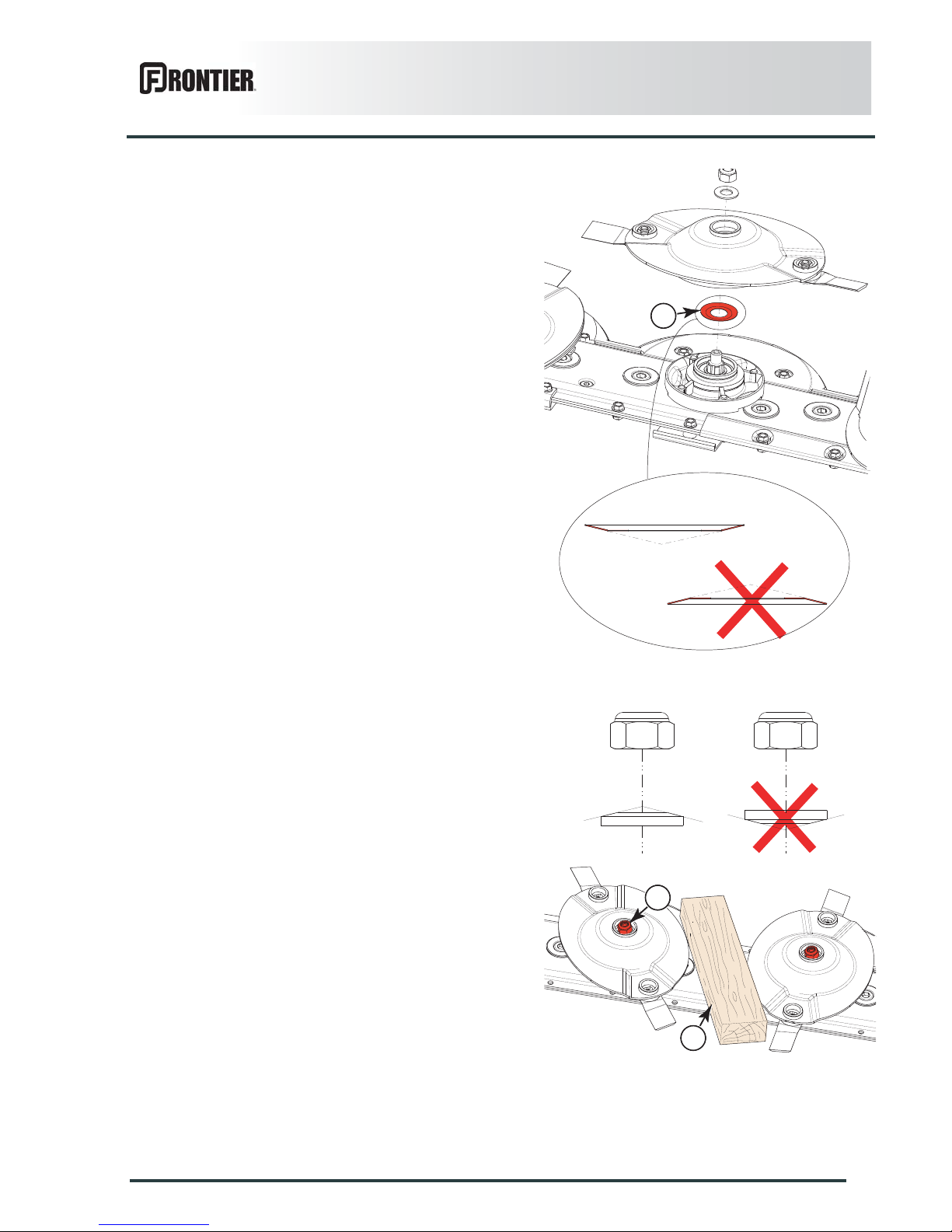
Disk replacement
Place a wooden wegde (2) between two disks to stop
them from moving.
Remove nut (1).
Remove the disk.
Replace knife lock-nuts and bo lts when they
have been removed 5 times.
Replace immediately all worn or distorted
knives. Never straighten a bent knife.
Always replace both knives per disk.
1
2
Page 49
Optional equipment
47
DM1160
When remounting:
Position conical center of dust seal (3) at the bottom.
Position their largest diameters at right angles to each
other.
Position conical center of spring washer at the top.
Place a wooden wegde (2) between two disks to stop
them from moving.
Tigthen nut (1).
- Torque: 18 daN m (133 lbf ft)
3
1
2
Page 50
48
Optional equipment
DM1160
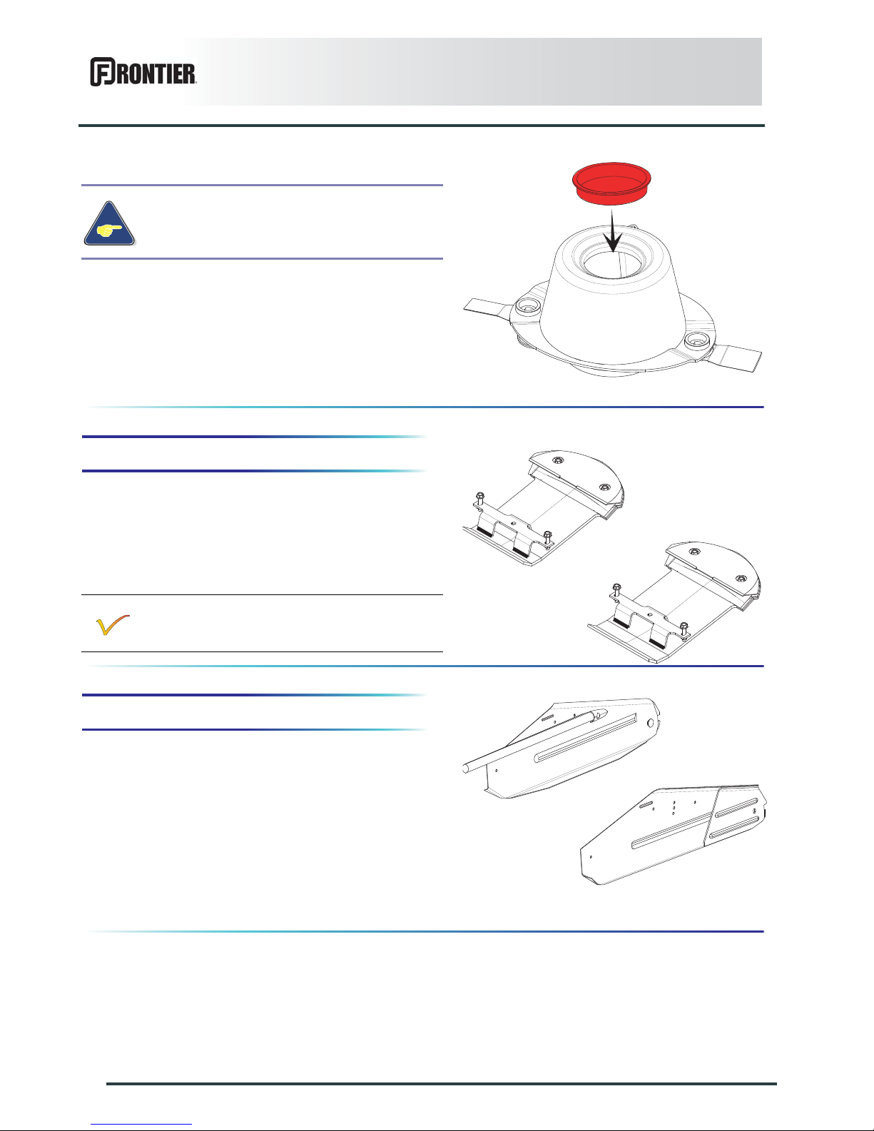
3. Raised skid shoes
Kit no. KN1016400
The raised skid shoes enable mowing higher, between
60 and 120 mm (2.4’’ - 4.8’’).
Replace the end disk skids by the 2 raised skid shoes.
4. 2 swath shields
Kit no. KN1036010
The 2 swath shields enable reducing the swath width to
approximately 1.30 m (4’3’’) depending on the crop
density.
When replacing the outer cone, make sure to
reinstall the cap.
The use of raised skid shoes is also
recommended on sticky grounds.
Page 51
Optional equipment
49
DM1160
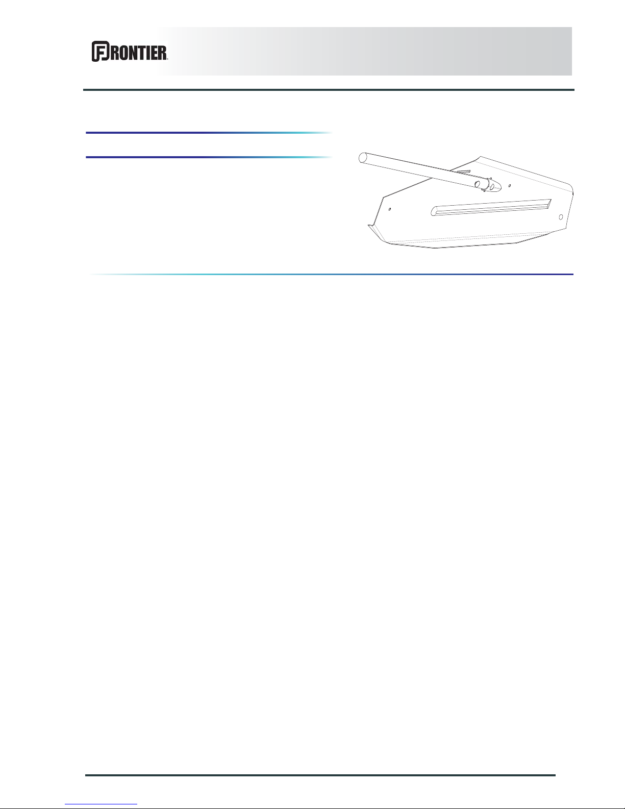
5. Inner swath shield
Kit no. KN1036000
The inner swath shield enables reducing the swath width
by approximately 300 mm (1’) depending on the crop
density.
Page 52
50
Maintenance and storage
DM1160
$MAINTENANCE AND STORAGE
1. Frequency chart
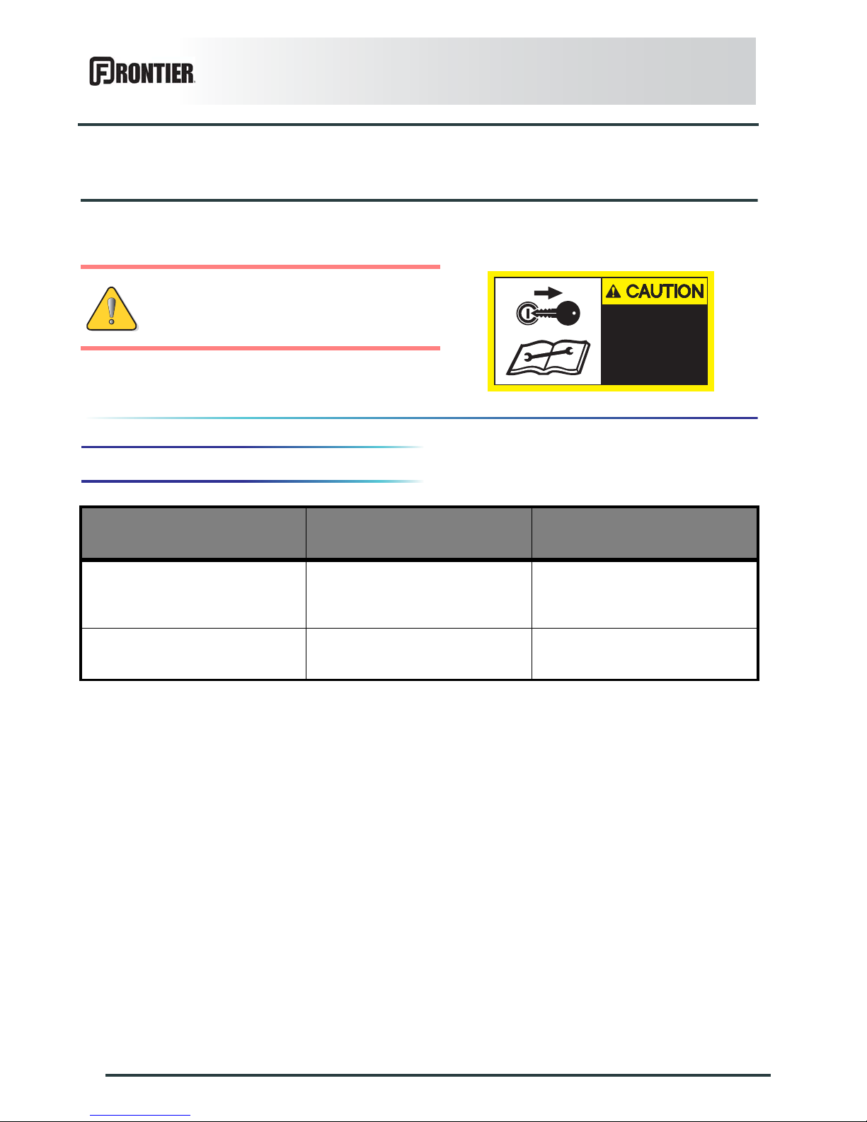
Before adjusting, maintaining or repairing
the machine, turn off ignition key and wait
until all moving parts have come to a
complete stop.
BEFORE ADJUSTING
MAINTAINING OR REPAIRING
THE MACHINE, TURN OFF THE
ENGINE, REMOVE IGNITION
KEY AND WAIT UNTIL ALL
MOVING PARTS HAVE COME TO
A COMPLETE STOP.
599 004 20
After the first 10 hours of
use
Every 200 hours or at the
end of the season
Oil change:
- Cutterbar.
- Side gearbox.
Check and clean:
- Breather plug
Page 53
Maintenance and storage
51
DM1160
2. Lubrication
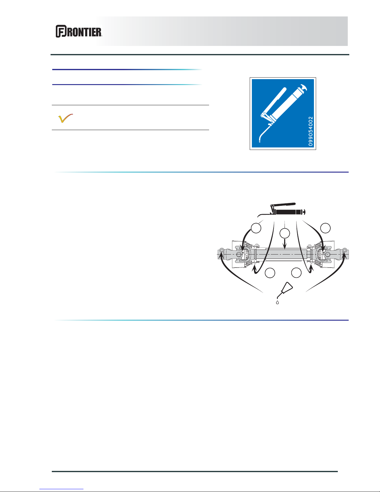
Clean grease zerks before greasing.
PTO shaft
Primary PTO shaft
- Every 8 hours:
• universal joints (1).
- Every 20 hours:
• transmission tube (2).
- Every 40 hours:
• Guide rings (3).
Lubricate with multi-purpose grease grade
NLGI 2.
11
3
3
2
Page 54
52
Maintenance and storage
DM1160
Cutterbar draining and refilling
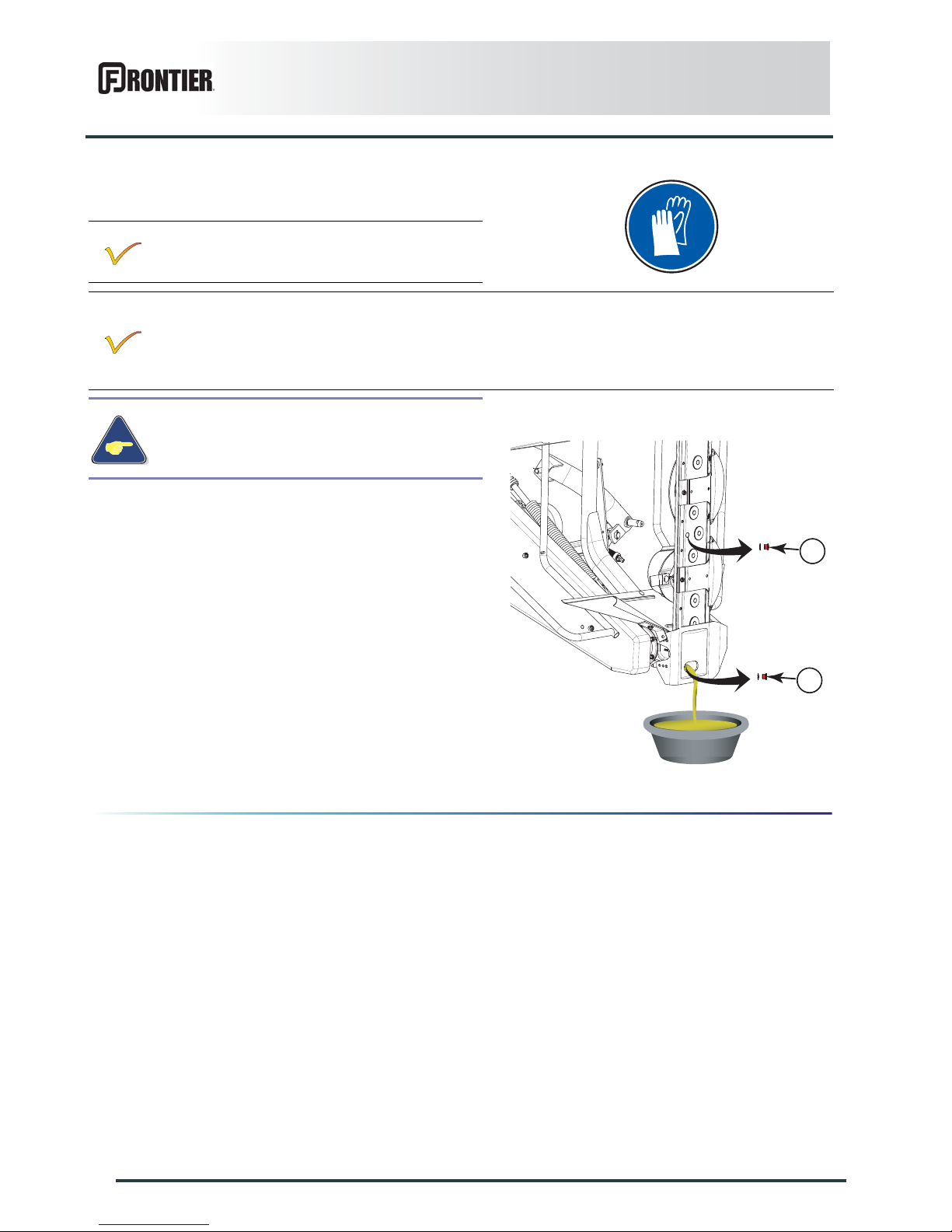
From the transport position:
- Place a container of sufficient capacity under drain
plug.
- Remove filler plug (1) and its washer.
- Remove drain plug (2) and its washer.
- Allow oil to drain completely.
- Wait for dripping to stop.
- Clean and reinstall drain plug (2) and its
washer. Replace if necessary.
- Pour the correct oil quantity and quality through the
opening of the filler plug.
- Clean and reinstall filler plug (1) and its
washer. Replace if necessary.
Before draining oil, operate the machine for a
few minutes so that the oil warms up.
The cutterbar is lubricated with 2.25 L (0.59 US gal) of extreme-pressure gear oil with viscosity grade
SAE 80W90 and API grade GL5.
When draining and refilling, it is recommended to use either a mineral base oil with viscosity grade SAE
80W90 and API grade GL5, or a synthetic base oil, type PAO (Poly-Alpha-Olefins) with a viscosity grade
equivalent to SAE 80W90.
Never use an oil of viscosity SAE 90 in the
cutterbar.
1
2
Page 55
Maintenance and storage
53
DM1160
Lateral gearbox draining
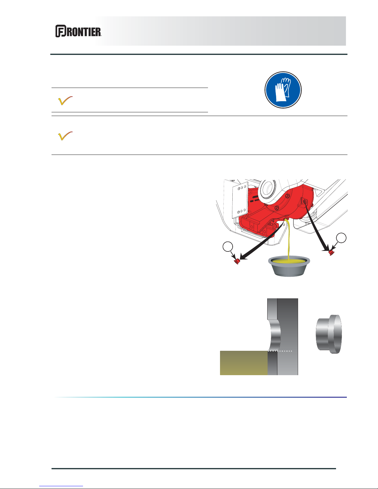
From the transport position:
- Remove filler plug (1) and its washer.
- Place a container of sufficient capacity under drain
plug.
- Remove drain plug (2) and its washer.
- Allow oil to drain completely.
- Wait for dripping to stop.
- Place the machine in working position.(See
chapter: Putting the machine into work position).
- Pour the correct oil quantity and quality through the
opening of the filler plug (1).
- Check lateral gearbox oil level:
• The oil level must reach the lower edge of the
emptying hole.
- Clean and reinstall drain plug (2) and its washer.
- Clean and reinstall filler plug (1) and its washer.
Before draining oil, operate the machine for a
few minutes so that the oil warms up.
2
1
The lateral gearbox is lubricated with 0.25 L (0.5 US pints) of extreme- pressure oil for mechanical
transmissions with viscosity grade SAE 80W90 and API grade GL5.
When draining and refilling, it is recommended to use either a mineral base oil with viscosity grade SAE
80W90 and API grade GL5, or a synthetic base oil, type PAO (Poly-Alpha-Olefins) with a viscosity grade
equivalent to SAE 80W90.
Page 56
54
Maintenance and storage
DM1160
3. Maintenance
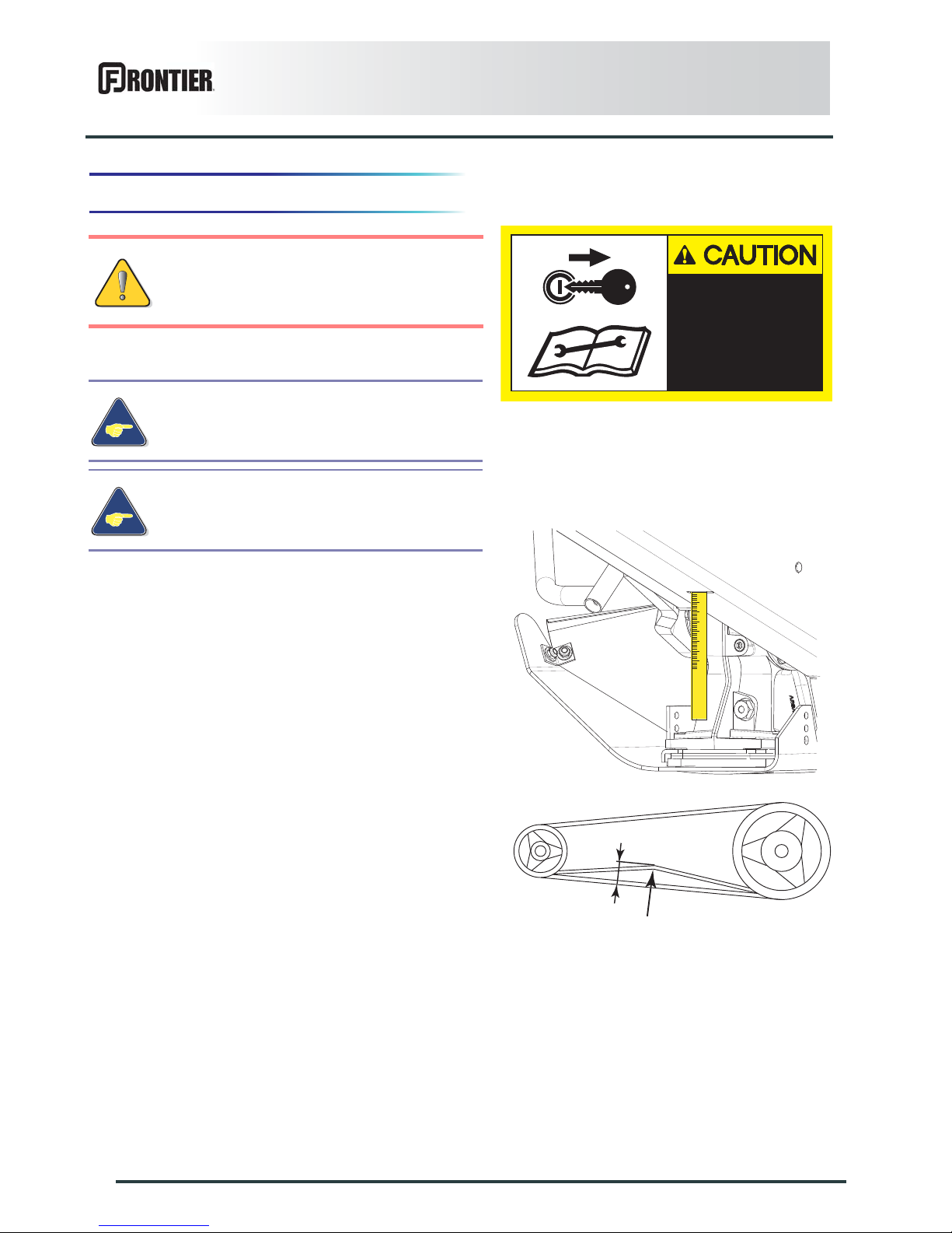
Belt tension
Checking the tension:
Apply a force of 3.5 daN (8 lbf) on the belt: the belt
should not deflect more than 10 mm (0.39’’) (H).
Before adjusting, maintaining or repairing
the machine, turn off ignition key and wait
until all moving parts have come to a
complete stop.
Regularly check belt tension and in particular
during the first hours of use.
Never replace belts individually.
Replace belts in full sets.
BEFORE ADJUSTING
MAINTAINING OR REPAIRING
THE MACHINE, TURN OFF THE
ENGINE, REMOVE IGNITION
KEY AND WAIT UNTIL ALL
MOVING PARTS HAVE COME TO
A COMPLETE STOP.
599 004 20
H
Page 57
Maintenance and storage
55
DM1160
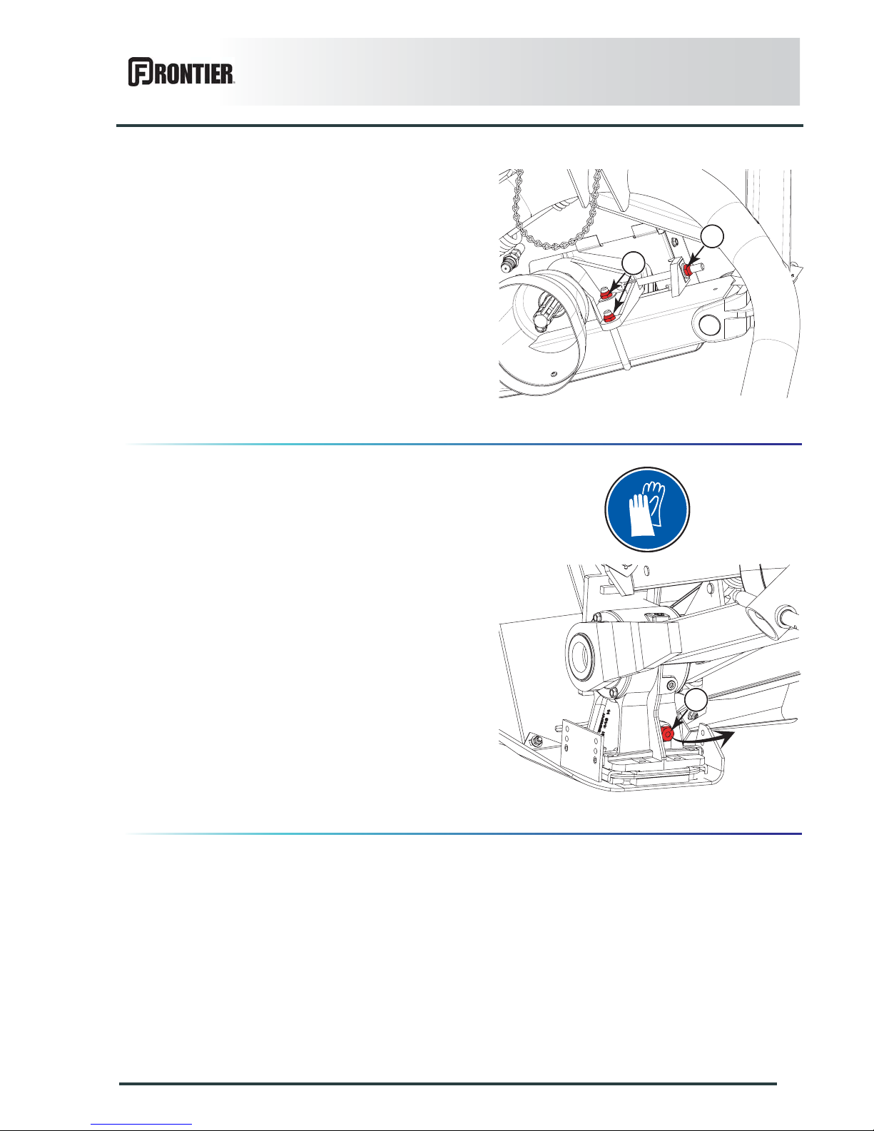
Adjusting the tension:
- Unscrew the 2 nuts (1).
- Tighten screw (2) to tension belts.
- Check belt tension.
- Tighten the 2 nuts (1).
- Torque: 13 daN m (96 lbf ft).
Breather plug checking and cleaning
From the working position:
Remove breather plug (1).
Clean and check breather plug for good functioning (1).
Reinstall breather plug (1).
1
2
1
Page 58
56
Maintenance and storage
DM1160
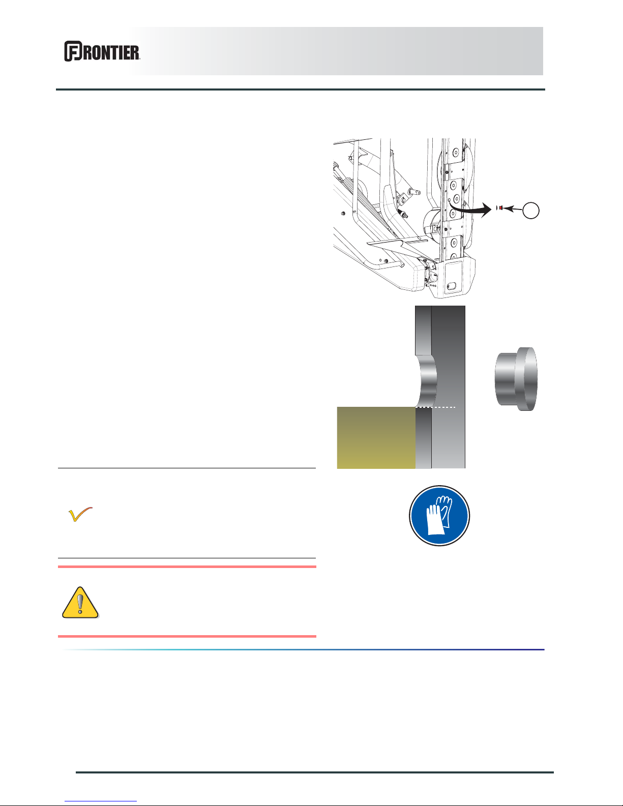
Checking cutterbar oil level
Regularly check the cutterbar oil level:
From the transport position:
• Remove filler plug (1).
• The oil must reach the lower edge of the filling hole.
• Top up if necessary.
• Clean and reinstall filler plug (1) and its
washer. (Replace if necessary).
If it is found that the transmission case is very hot
to touch by hand, there is no cause of alarm
provided:
- Lubrication recommendations have been
respected.
- Disks can be rotated freely by hand when the
machine is hot.
Before checking that the disks rotate freely
by hand:
- Turn off the engine, remove ignition key
and wait until all moving parts have
come to a complete stop.
1
Page 59
Maintenance and storage
57
DM1160
Inspection of knives and securing elements
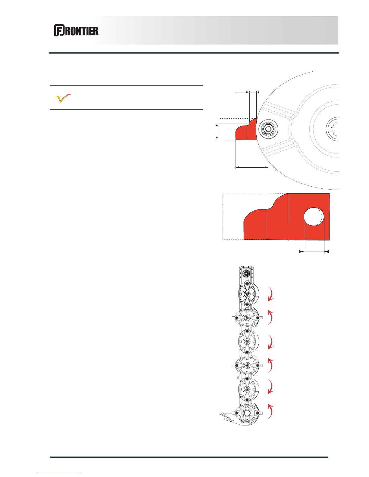
Knives
Inspect systematically all knives before the machine is
operated to:
• guarantee the cutting quality.
• guarantee safety in use.
• Prevent cutterbar damage risks.
Replace knives in the following cases:
- Damaged knives. Very rough conditions can cause
knives to crack and become deformed.
- Worn knives
Knife length C must exceed 80 mm (3.15’’).
Knife width B, measured at a distance A of 10 mm (0.4’’)
from the disk edge must exceed 20 mm (0.8’’).
The hole L for the securing bolt must not become ova l by
more than 20 mm (0.8’’).
Always replace both knives per disk to avoid creating an
out-of-balance force.
Immediately replace worn or damaged parts with
original manufacturer parts.
L
A
B
C
Page 60
58
Maintenance and storage
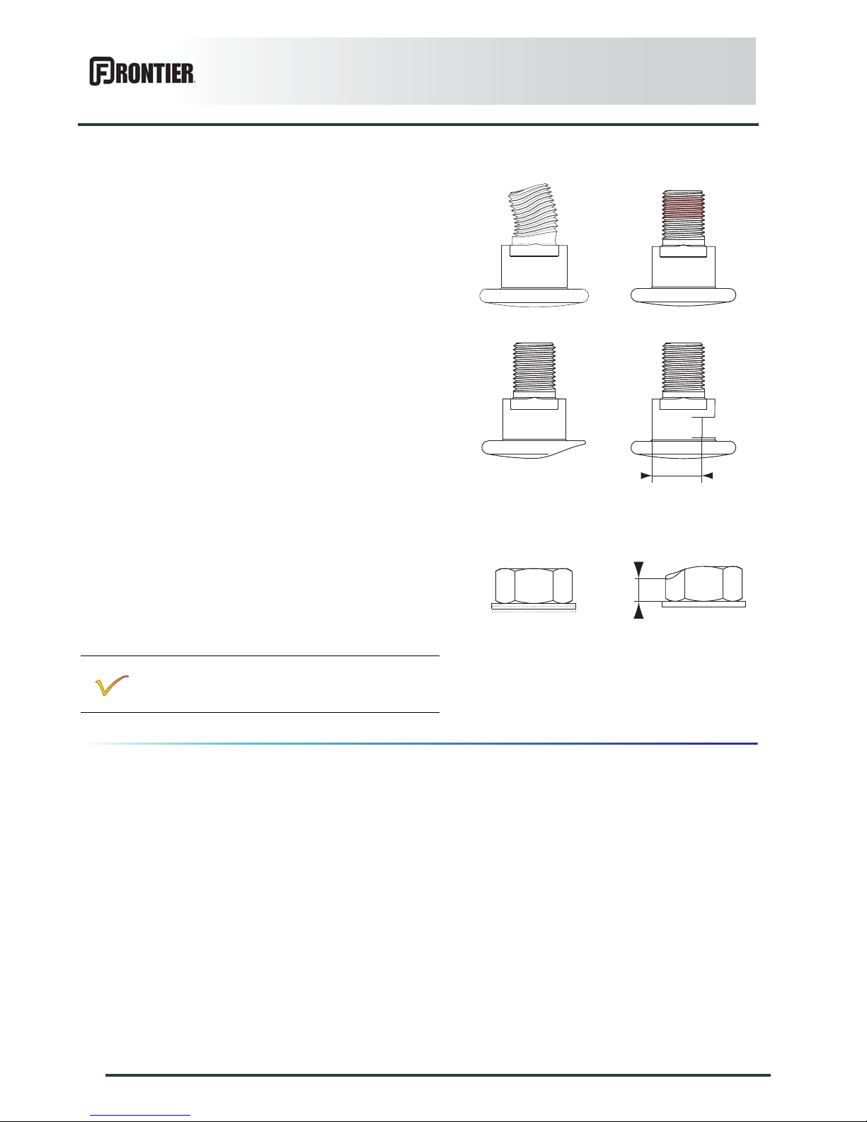
DM1160
Fixing elements
Check the fixing elements:
- After hitting an obstacle.
- When replacing knives.
- At the beginning of each season.
The fixing bolts should be changed in the following
cases:
- When there is visible distortion.
- When the locking compound is worn or inoperational.
- When the bolt head wear reaches the center line of
the bolt.
- When diameter D of the bolt shoulder is less than
15 mm (0.6’’).
- After having been removed 5 times.
Replace nuts in the following cases:
- When the contact washer has lost its elasticity.
- When the contact washer loosens itself from the nut.
- When nut wear reaches a = 5 mm (0.2’’).
- After having been removed 5 times.
-
Check the condition of the fixing elements
regularly and also the torque of the knife-fixing
bolt: 12 daN m (89 lbf ft).
D
a
Page 61
Maintenance and storage
59
DM1160
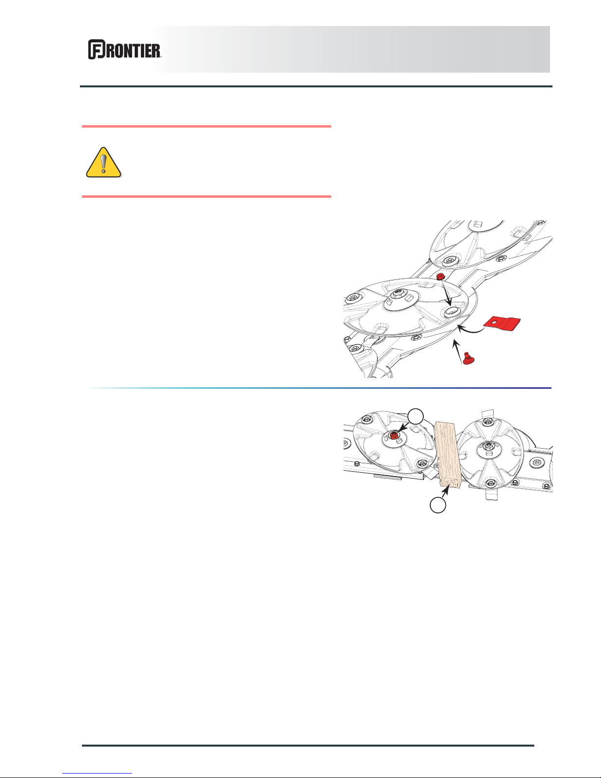
Knife replacement
Clean the nut case.
Place a wooden wedge between two disks to stop them
from rotating.
Loosen nut using box wrench supplied with the machine .
Remove bolt through opening located at the front of the
disk guard.
Knives can be turned over on the same disk to use the
other cutting edge or replac ed. On each k nife, an arro w
indicates the disk's direction of rotation.
Make sure that the securing nut and bolt are in good
condition and if necessary, replace them.
Torque knife locknut to 7.5 daN m (55 lbf ft).
Dull knives require more horse power and have a
negative effect on the cut quality.
Disk replacement
Place a wooden wegde (2) between two disks to stop
them from moving.
Remove nut (1).
Remove the disk.
Replace knife lock-nuts and bolts when they
have been removed 5 times.
Replace immediately all worn or distorted
knives. Never straighten a bent knife.
Always replace both knives per disk.
1
2
Page 62
60
Maintenance and storage
DM1160
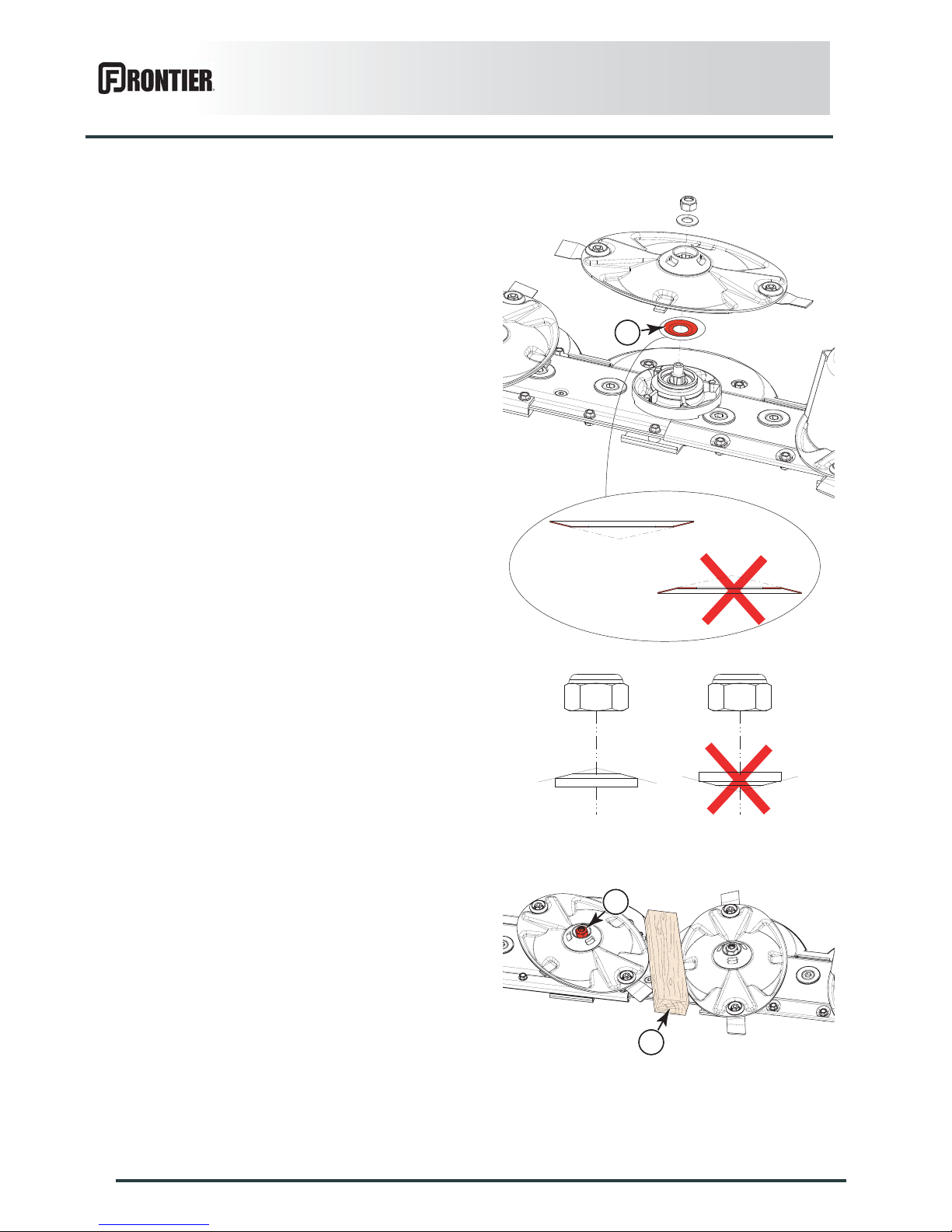
When remounting:
Position conical center of dust seal (3) at the bottom.
Position their largest diameters at right angles to each
other.
Position conical center of spring washer at the top.
Place a wooden wegde (2) between two disks to stop
them from moving.
Tigthen nut (1).
- Torque: 18 daN m (133 lbf ft)
3
1
2
Page 63
Maintenance and storage
61
DM1160
4. Storage
At the end of each season
- Clean the machine thoroughly.
- Drain all gearboxes and cutterbar and refill with new
oil (see "Lubrication" chapter).
- Touch up any areas of damaged paintwork.
- Put the machine under cover in a dry place.
- Inspect and replace worn knives and bolts (See
section "Inspection of knives and securing elements").
- Slacken V-belts and check their condition.
- Fully lubricate the machine.
At the start of each season
- Check that all nuts and bolts are sufficiently tightened.
- Retension belts.
- Check that safety breakback system functions.
- Re-read the operators' manual.
- Make sure all the guards are in place.
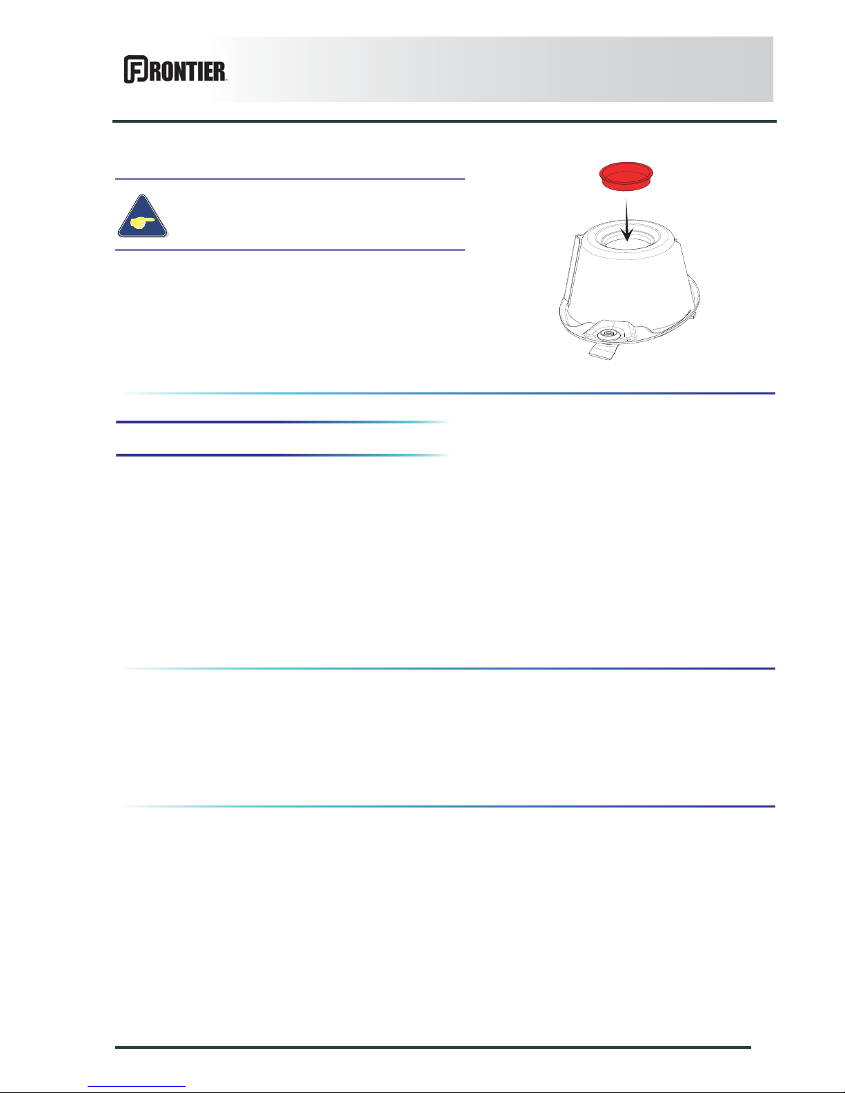
When replacing the outer cone, make sure to
reinstall the cap.
Page 64

62
Troubleshooting guide
DM1160
$TROUBLESHOOTING GUIDE
-
Problem Cause Remedy
Uneven stubble. Dull or broken knives. Replace knives.
Knives not installed correctly. Make sure the arrow on the
knife upper face is pointing in
the disk's direction of rotation.
Too low PTO speed (rotational
frequency).
Increase speed to 540 min
-1
.
Soil build up in front of the
cutterbar.
Very wet working conditions. Adjust main frame height with
regards to the ground.
Bad ground contour
adaptation.
Incorrect main frame setting. Adjust main fra m e he ig ht with
regards to the ground.
Excessive ground speed. Reduce ground speed.
Insufficient cutterbar ground
clearance in "headland turn"
position.
Incorrect tractor lift linkage
setting.
See machine attachment.
Too long levelling rod
adjustment on tractor 3-point
lift.
Shorten levelling rods on
tractor 3-point lift.
Lengthened cylinder rod. Shorten cylinder rod.
Considerable vibrations. Nylon plug missing. Immediately replace missing
cap.
Too frequent safety breakback
release.
Insufficient spring washer
compression.
Increase spring washer
compression.
Poor division between cut and
uncut crop.
Tangled and down crops. Check swath shield retaining
spring tension.
Page 65

Page 66

Page 67

Page 68

Imprimé en France par KUHN
Printed in France by KUHN
 Loading...