


OPERATOR'S MANUAL
BOX BLADES
BB3272
BB3284
BB3296
BB32_5TL15288_07/10

TO THE DEALER:
Assembly and proper installation of this product is the responsibility of the Frontier dealer. Read manual instructions and safety rules. Make sure all items on the Dealer’s Pre-Delivery and Delivery Check
Lists in the Owner’s/Operator’s Manual are completed before releasing equipment to the owner.
The dealer must complete the Warranty Registration located on the Frontier website.
TO THE OWNER:
Read this manual before operating your Frontier equipment. The information presented will prepare
you to do a better and safer job. Keep this manual handy for ready reference. Require all operators to
read this manual carefully and become acquainted with all the adjustment and operating procedures
before attempting to operate. Replacement manuals can be obtained from your selling dealer.
The equipment you have purchased has been carefully engineered and manufactured to provide
dependable and satisfactory use. Like all mechanical products, it will require cleaning and upkeep.
Lubricate the unit as specified. Observe all safety information in this manual and safety decals on the
equipment.
For service, your authorized Frontier dealer has trained mechanics, genuine Frontier service parts, and
the necessary tools and equipment to handle all your needs.
Use only genuine Frontier service parts. Substitute parts will void the warranty and may not meet standards required for safe and satisfactory operation. Record the model number and serial number of your
equipment in the spaces provided:
Model:____________________________________ Date of Purchase:_________________
Serial Number: (see Safety Decal section for location)_______________________________
Provide this information to your dealer to obtain correct repair parts.
Throughout this manual, the term IMPORTANT is used to indicate that failure to observe can cause
damage to equipment. The terms CAUTION,WARNING and DANGER are used in conjunction with the
Safety-Alert Symbol, (a triangle with an exclamation mark), to indicate the degree of hazard for items
of personal safety.
This Safety-Alert Symbol indicates a hazard and means ATTENTION!
BECOME ALERT! YOUR SAFETY IS INVOLVED!
DANGER
WARNING
CAUTION
Indicates an imminently hazardous situation that, if not avoided, will result in
death or serious injury.
Indicates a potentially hazardous situation that, if not avoided, could result in
death or serious injury, and includes hazards that are exposed when guards
are removed.
Indicates a potentially hazardous situation that, if not avoided, may result in
minor or moderate injury.
IMPORTANT
Indicates that failure to observe can cause damage to equipment.
NOTE
Indicates helpful information.
Introduction ii

TABLE OF CONTENTS
INTRODUCTION . . . . . . . . . . . . . . . . . . . . . . . . . . . . . . . . . . . . . . . . . . . . . . ii
SPECIFICATIONS / GENERAL INFORMATION . . . . . . . . . . . . . . . . . . . . . . . . . . . . . . . 1
SAFETY DECALS . . . . . . . . . . . . . . . . . . . . . . . . . . . . . . . . . . . . . . . . . . . . . . . 2 - 3
SAFETY RULES . . . . . . . . . . . . . . . . . . . . . . . . . . . . . . . . . . . . . . . . . . . . . . 4 - 6
DEALER INSTRUCTIONS . . . . . . . . . . . . . . . . . . . . . . . . . . . . . . . . . . . . . . . . . . . . 7
OPERATION . . . . . . . . . . . . . . . . . . . . . . . . . . . . . . . . . . . . . . . . . . . . . . . . . 8 - 10
OWNER SERVICE . . . . . . . . . . . . . . . . . . . . . . . . . . . . . . . . . . . . . . . . . . . . . . . . . 11 - 12
PARTS CATALOG . . . . . . . . . . . . . . . . . . . . . . . . . . . . . . . . . . . . . . . . . . . . . . . . 13 - 14
BOLT SIZE AND BOLT TORQUE CHART . . . . . . . . . . . . . . . . . . . . . . . . . . . . . . . . . . 15
NOTES . . . . . . . . . . . . . . . . . . . . . . . . . . . . . . . . . . . . . . . . . . . . . . . . . . . . . . . . . . 16
Table of Contents

SPECIFICATIONS
BB3272 BB3284 BB3296
3-Point Hitch Category I and II Quick Hitch
(iMatch Compatible)
Working Width 72" 84" 96"
Tractor HP (MAX) 80 HP 80 HP 80 HP
Shipping Weight 856 lbs. 970 lbs. 1086 lbs.
Approximate Operating
Weight
Beam Type Tubular Scarier Beam Tubular Scarier Beam Tubular Scarier Beam
Scarier Shanks Notched Four Position Notched Four Position Notched Four Position
Points Heat Treated Points Heat Treated Points Heat Treated Points
Capacity 21 cu. ft. 24.50 cu. ft. 28 cu. ft.
Cutting Edges (2) 1/2” x 6’ Reversable (2) 1/2” x 6’ Reversable (2) 1/2” x 6’ Reversable
Beam Size 4” x 4” x 3/8” 4” x 4” x 3/8” 4” x 4” x 3/8”
End Plate Thickness 1/2” 1/2” 1/2”
Height 20” 20” 20”
Depth 26 1/2” 26 1/2” 26 1/2”
Tailgate Floating Floating Floating
Assembly Time 15 min. 15 min. 15 min.
Moldboard Thickness 1/4” 1/4” 1/4”
816 lbs. 911 lbs. 1036 lbs.
Category I and II Quick Hitch
(iMatch Compatible)
Category I and II Quick Hitch
(iMatch Compatible)
GENERAL INFORMATION
The purpose of this manual is to assist you
in operating and maintaining your Box
Blade. Read it carefully. It furnishes information and instructions that will help you
achieve years of dependable performance.
These instructions have been compiled
from field experience and engineering data.
Some information may be general in nature,
due to unknown and varying operating
conditions. However, through experience
and these instructions, you should be able
to develop procedures suitable to your particular situation.
1 Specifications
The illustrations and data used in this
manual were current at the time of printing. However, due to possible inline production changes, your machine may vary
slightly in detail. We reserve the right to
redesign and change the machines as
may be necessary without notification.
Throughout this manual, references are
made to right and left direction. These are
determined by standing behind the tractor
facing the direction of forward travel.

SAFETY & INSTRUCTIONAL DECALS
ATTENTION! BECOME ALERT! YOUR SAFETY IS INVOLVED!
FAILURE TO FOLLOW THESE INSTRUCTIONS COULD RESULT IN SERIOUS INJURY OR DEATH
Replace Decals Immediately If Damaged!
5TL15286B
5TL15286C
5TL15286A
Safety Decals 2

BB3296 ONLY
SAFETY REFLECTOR DECALS
ATTENTION! BECOME ALERT! YOUR SAFETY IS INVOLVED!
FAILURE TO FOLLOW THESE INSTRUCTIONS COULD RESULT IN SERIOUS INJURY OR DEATH
Replace Decals Immediately If Damaged!
9” YELLOW REFLECTORS
5TL15200
3 Safety Decals
9” RED REFLECTORS
5TL15199
Check that all reflector decals are installed
and in good condition. Replace if decals are
worn or damaged.

SAFETY RULES
ATTENTION! BECOME ALERT! YOUR SAFETY IS INVOLVED!
Safety is a primary concern in the design and
manufacture of our products. Unfortunately, our
efforts to provide safe equipment can be wiped
out by an operator’s single careless act.
In addition to the design and configuration of
equipment, hazard control and accident prevention are dependent upon the awareness, concern, judgement, and proper training of personnel involved in the operation, transport, maintenance and storage of equipment.
It has been said “The best safety device is an
informed, careful operator.”We ask you to be
that kind of operator.
TRAINING
• Safety instructions are important! Read all
attachment and power unit manuals; follow all
safety rules and safety decal information.
(Replacement manuals are available from selling dealer.) Failure to follow instructions or
safety rules can result in serious injury or
death.
• If you do not understand any part of this manual and need assistance, see your dealer.
• Operators must be instructed in and be capable of the safe operation of the equipment, its
attachments, and all controls. Do not allow anyone to operate this equipment without proper
instructions.
rough-soled work shoes and protective equipment for eyes, hair, hands, hearing, and head;
and respirator or filter mask where appropriate.
• Make sure attachment is properly secured,
adjusted, and in good operating condition.
• Power unit must be equipped with ROPS or
ROPS cab and seat belt. Keep seat belt
securely fastened. Falling off power unit can
result in death from being run over or crushed.
Keep foldable ROPS system in “locked up”
position at all times.
• A minimum 20% of tractor and equipment
weight must be on the tractor front wheels
when attachments are in transport position.
Without this weight, tractor could tip over, causing personal injury or death. The weight may be
attained with a loader, front wheel weights, ballast in tires or front tractor weights. Weigh the
tractor and equipment. Do not estimate.
TRANSPORTATION
• Always comply with all state and local laws
governing highway safety and lighting and
marking requirements.
• Never allow riders on power unit or attachment.
• Do not operate or transport on steep slopes.
• Never allow children or untrained persons to
operate equipment.
• Train all new personnel and review instruction’s
frequently with existing workers. A person who
has not read and understood all operating and
safety instructions is not qualified to operate the
machine. An untrained operator exposes himself
and bystanders to possible serious injury or
death.
PREPARATION
• Always wear relatively tight and belted clothing to
avoid getting caught in moving parts.Wear sturdy,
• Use extreme care and reduce ground speed
on slopes and rough terrain.
• Do not operate or transport equipment while
under the influence of alcohol or drugs. Consult
your doctor about operating this machine while
taking prescription medications.
OPERATION
• Never go underneath equipment (lowered to
the ground or raised) unless it is properly
blocked and secured. Never place any part of
the body underneath equipment or between
Safety Rules continued on next page.
Safety Rules 4

SAFETY RULES
ATTENTION! BECOME ALERT! YOUR SAFETY IS INVOLVED!
Safety Rules continued from previous page.
OPERATION (cont’d)
moveable parts even when the engine has
been turned off. Hydraulic system leak down,
hydraulic system failures, mechanical failures,
or movement of control levers can cause
equipment to drop or rotate unexpectedly and
cause severe injury or death.
• Always comply with all state and local laws
governing highway safety and lighting and
marking requirements.
• Operate only in daylight or good artificial
light.
• Keep bystanders away from equipment.
• Keep hands, feet, hair, and clothing away
from equipment while engine is running. Stay
clear of all moving parts.
• Power unit must be equipped with ROPS or
ROPS cab and seat belt. Keep seat belt
securely fastened. Falling off power unit can
result in death from being run over or crushed.
Keep foldable ROPS system in “locked up”
position at all times.
• Never allow riders on power unit or attachment.
• Always sit in power unit seat when operating
controls or starting engine. Securely fasten
seat belt, place transmission in neutral, engage
brake, and ensure all other controls are disengaged before starting power unit engine.
• Look down and to the rear and make sure
area is clear before operating in reverse.
• Use extreme care when working close to fences,
ditches, other obstructions, or on hillsides.
• Do not operate or transport on steep slopes.
• Do not stop, start, or change directions sud-
denly on slopes. Always operate down slopes;
never across the face.
• Use extreme care and reduce ground speed
on slopes and rough terrain.
• Keep alert and watch the front as well as the
rear when operating.
• When making adjustments, be careful to keep
hands and feet clear of sliding parts and possible pinch points.
• Stop power unit and equipment immediately
upon striking an obstruction. Turn off engine,
remove key, inspect, and repair any damage
before resuming operation.
• Before leaving operator’s seat, lower lift arms
and put attachment on the ground. Engage
brake, stop engine, remove key, and remove
seat belt.
MAINTENANCE
• Always wear relatively tight and belted clothing to avoid getting caught in moving parts.
Wear sturdy, rough-soled work shoes and protective equipment for eyes, hair, hands, hearing, and head; and respirator or filter mask
where appropriate.
• Never go underneath equipment (lowered to
the ground or raised) unless it is properly
blocked and secured. Never place any part of
the body underneath equipment or between
moveable parts even when the engine has
been turned off. Hydraulic system leak down,
hydraulic system failures, mechanical failures,
or movement of control levers can cause equipment to drop or rotate unexpectedly and cause
severe injury or death.
• When performing maintenance or repairs
make sure the equipment is in the lowered
position and both the mainframe and gangs are
properly blocked and secured to prevent rolling.
Safety Rules continued on next page.
5 Safety Rules

SAFETY RULES
ATTENTION! BECOME ALERT! YOUR SAFETY IS INVOLVED!
Safety Rules continued from previous page.
MAINTENANCE(cont’d)
Failure to do so can cause serious injury or
death.
• Make sure attachment is properly secured,
adjusted, and in good operating condition.
• Before leaving operator’s seat, lower lift arms
and put attachment on the ground. Engage
brake, stop engine, remove key, and remove
seat belt.
• Never perform service or maintenance with
engine running.
• Keep all persons away from operator control
area while performing adjustments, service, or
maintenance.
• Tighten all bolts, nuts, and screws to torque
chart specifications. Check that all cotter pins
are installed securely to ensure equipment is in
a safe condition before putting unit into service.
STORAGE
• Block equipment securely for storage.
• Keep children and bystanders away from stor-
age area.
Safety Rules 6

DEALER INSTRUCTIONS
Pre-Assembly
Attaching Scarifier Shanks in the Box
Blade
Remove scarifier shanks and shank keys from
carton inside box scraper.
Block up machine by placing two 4” x 4” blocks
under each side frame of the box blade.
Insert the scarifier shank in the shank hole from
the bottom up.
Note: The scarifier shank has four notches for
adjustments. The bottom notch is for transport.
The top three notches are for ground penetration to be determined by the user.
After inserting scarifier shank, place shank key
on the back side of shank. This will prevent the
shank from working loose.
Dealer Checklist
(Dealer’s Responsibility)
Inspect the equipment thoroughly after assembly to be certain it is set up properly before
delivering it to the customer. The following
check list is a reminder of points to inspect.
Check off each item if it is found satisfactory or
after proper adjustment is made.
____ Show customer the safe, proper procedures to be used when mounting, dismounting,
and storing equipment.
____ For mounted units, add wheel weights,
ballast in front tires, and/or front tractor weight
to enhance front end stability. A minimum 20%
of tractor and equipment gross weight must be
on front tractor wheels. When adding weight to
attain 20% of tractor and equipment weight on
front tractor wheels, you must not exceed the
ROPS weight certification. Weigh the tractor
and equipment. Do not estimate!
____ Show customer how to make adjustments.
____ Present Owner’s/Operator’s Manual and
request that customer and all operators read it
before operating equipment. Point out the
manual safety rules, explain their meanings
and emphasize the increased safety hazards
that exist when safety rules are not followed.
____ Point out the safety decals. Explain their
meaning and the need to keep them in place
and in good condition. Emphasize the increased
safety hazards when instructions are not followed.
____ Check that all safety decals are installed
and in good condition. Replace if damaged.
____ Check all bolts to be sure they are tight.
____ Check that all cotter pins and safety pins
are properly installed. prior to delivery to customer.
____ Explain to customer the potential crushing
hazards of going underneath raised equipment.
Instruct customer that service work does not
require going underneath unit and never to do
so.
____ Complete the Warranty Registration
located on the Frontier website.
7 Dealer Instructions

Operation
Safety is a primary concern in the design and
manufacture of our products. Unfortunately, our
efforts to provide safe equipment can be wiped
out by an operator’s single careless act.
In addition to the design and configuration of
equipment, hazard control and accident prevention are dependent upon the awareness, concern, judgement, and proper training of personnel involved in the operation, transport, maintenance and storage of equipment.
It has been said “The best safety device is an
informed, careful operator.”We ask you to be
that kind of operator.
The operator is responsible for the safe operation
of this equipment. The operator must be properly
trained. Operators should be familiar with the
equipment, the tractor, and all safety practices
before starting operation. Read the safety rules
and safety decals on pages 2-6.
Owner should check and tighten all hardware after
the first hour of operation. The break in stage of
your new box blade can cause minimal loosening
of hardware. Please see Bolt Torque Chart (page
16) for proper torque information.
• NEVER GO UNDERNEATH EQUIPMENT.
Never place any part of the body underneath
equipment or between moveable parts even
when the engine has been turned off. Hydraulic
system leak down, hydraulic system failures,
mechanical failures, or movement of control
levers can cause equipment to drop or rotate
unexpectedly and cause severe injury or death.
• Service work does not require going underneath.
• Read Manual for service instructions or have
service performed by a qualified dealer.
• Stop tractor and implement immediately upon
striking an obstruction. Turn off engine, remove
key, inspect, and repair any damage before
resuming operation.
• Always wear relatively tight and belted clothing
to avoid entanglement in moving parts. Wear
sturdy, rough-soled work shoes and protective
equipment for eyes, hair, hands, hearing, and
head.
Owner/Operator Pre-Operation
Checklist
(Owner’s/Operator’s Responsibility)
WARNING
• Power unit must be equipped with ROPS or
ROPS cab and seat belt. Keep seat belt
securely fastened. Falling off power unit can
result in death from being run over or crushed.
Keep foldable ROPS systems in “locked up”
position at all times.
• Never allow children or untrained persons to
operate equipment.
• Keep bystanders away from equipment.
____ Review and follow all safety rules and
safety decal instructions on page 2 through
page 6.
____ Check that equipment is properly and
securely attached to tractor.
____ Check that all safety decals are installed
and in good condition. Replace if damaged.
____ Check that all hardware is properly
installed and secured.
____ Do not allow riders.
____ Make sure tractor ROPS or ROPS CAB
and seat belt are in good condition. Keep seat
belt securely fastened during operation.
Operation 8

Connecting Box Blade to the Tractor
The box blade is compatible with tractors
equipped with Category 1 or Category 2, 3-point
hitch systems that use side-swing type lower lift
arms. The box blades will also fit tractors
equipped with a Category 1 and 2 Quick Hitch
system.
NOTE: When attaching box blade to any hitch
other than a standard Category 1 hitch, bushings must be purchased separately.
Category 1 Standard (Figure 1)
1. Attach the tractor’s lower lift arms to the box
blade through the lower, inner set of holes.
Figure 2. Category 1 Quick Hitch Set-up
Category 1 Quick Hitch (Figure 2)
2. Use the hitch pin supplied with your box
blade and re-install the lynch pins.
3. Attach the tractor’s top link to the box blade’s
mast using the heavy-duty top link pin and
lynch pin supplied with the top link.
Figure 1. Category 1 and 2 Hitch Set-up
1. Connect the tractor’s Quick Hitch to the box
blade through the upper, inner set of holes.
2. Slide lower sleeve (sold seperatly) over the
mounting pin supplied with box blade. Re-install
lynch pins.
3. Slide upper sleeve over the heavy-duty top
link pin supplied with top link. Reinstall retaining
pin.
Category 2 Standard (Figure 1)
1. Use Category 1 Standard instructions except
use lower, outer set of holes.
9 Operation
Figure 3. Category 2 Quick Hitch Set-up
Category 2 Quick Hitch (Figure 3)
1. Connect the tractor’s Quick Hitch to the box
blade through the upper, outer set of holes.
2. Slide upper sleeve over the heavy-duty top
link pin supplied with top link. Reinstall retaining
pin.

Operation(cont.)
ADJUSTING TOP LINK
The box blade is leveled by adjusting the
length of the tractor’s top link.
• Shortening the top link will deepen the scarifier tooth penetration.
• Lengthening the top link will provide better
scraping and leveling action.
• Experience will allow the operator to determine the best setting for the application being
done.
SCARIFYING
1. Place the scarifier shanks in position with
the points facing toward the tractor.
2. Lock into position with the shank key provided. The lower shank position provides the
greatest ground penetration.
3. Lower the box blade and drive the tractor
ahead to begin the scarifying operation.
4. Adjust the depth of the scarifier by tilting
the unit with the tractor top link. Shortening
the top link will provide deeper and more
aggressive operation.
3. To change the level of the box blade, shorten
or lengthen the tractor lift arm tilt link to provide
the correct slope.
4. Spread material by gradually raising the box
blade as the tractor moves forward. Top link
adjustment for loose or previously scarified
material will differ from adjustment for hard or
compacted material.
BACKFILLING
1. Raise or remove scarifier shanks.
2. Lower the box blade to the ground and back
up into the fill material.
3. Shorten the top link to raise the cutting blade
and control how much the box blade digs in.
LEVELING
1. Raise or remove scarifier shanks.
2. Shorten the top link so the cutting edge
clears the ground.
3. Drive forward with the box blade in this position and loose material will be leveled.
SCRAPING
1. Raise or remove the scarifier shanks.
Lower the box blade and drive forward to
move material.
2. Adjust the depth of the box blade by tilting
the unit with the tractor top link. Shortening
the top link when scraping will transfer more
weight on the front of the box blade and will
raise the cutting blade to provide a more shallow cut.
NOTE: When the top link is adjusted properly,
the bowl of the box blade should fill easily and
material can be pulled to a desired location.
WARNING
STORAGE
• Block equipment securely for storage (see
Blocking Up Box Blade, page 11).
• Keep children and bystanders away from
storage area.
Operation 10

Owner Service
The information in this section is written for operators who possess basic mechanical skills. If you
need help, your dealer has trained service technicians available. For your protection, read and
follow the safety information in this manual.
WARNING
• NEVER GO UNDERNEATH EQUIPMENT.
Never place any part of the body underneath
equipment or between moveable parts even
when the engine has been turned off. Hydraulic
system leak down, hydraulic system failures,
mechanical failures, or movement of control
levers can cause equipment to drop or rotate
unexpectedly and cause severe injury or death.
• Service work does not require going underneath.
• Read Manual for service instructions or have
service performed by a qualified dealer.
BLOCKING UP BOX BLADE
WARNING
NOTE: To service the box blade when attached
to the tractor, it must be blocked up off the
ground.
1. Place two 4" x 4" blocks under each side frame
of the box blade as shown in Figure 4.
2. Lower the box blade to rest securely on the
blocks.
3. Do not block the machine any higher than
needed for removing the shanks or cutting edge.
Storage
When storing your box blade make sure the unit
is placed on level ground and that the box blade
is properly chocked by bracing with 4” x 4” blocks
on the front and rear side of each end of the box
blade.
WARNING
• Keep all persons away from operator control
area while performing adjustments, service, or
maintenance.
• Before dismounting power unit or performing
any service or maintenance, follow these steps:
disengage power to equipment, lower the 3 point
hitch and all raised components to the ground,
CAUTION
operate valve levers to release any hydraulic
pressure, set parking brake, stop engine, remove
key, and unfasten seat belt.
• Always wear relatively tight and belted clothing
to avoid entanglement in moving parts. Wear
sturdy, rough-soled work shoes and protective
equipment for eyes, hair, hands, hearing, and
head.
4” x 4” blocks securing gang for storage
Figure 4
11 Owner Service

REMOVING SCARIFIER SHANKS
1
2
REPLACING SCARIFIER TOOTH
Scarifier shanks have four operating positions in
the box blade. They may be removed if scarifying
action is not needed.
1. Block up machine by placing two 4" x 4" (10
x 10 cm) blocks under each side-frame of the box
blade (see Page 11, Figure 4).
2. Lower the box blade to rest securely on the
blocks.
NOTE: Do not block the machine any higher than
necessary to remove the shanks or cutting
edge.
3. Remove shank key for disengagement of
shank.
4. Disengage shank retaining notch from box
blade frame.
5. Remove shank from bottom of tube (see
Figure 5).
1. Remove scarifier shank from the scarifier bar.
2. To replace the tooth from the scarifier shank
you will need a hand grinder to remove the weld
that bonds the tooth to the shank. A new tooth
can be rewelded to the shank. Or you can order
a complete replacement scarifier shank from your
dealer.
3. Reinstall the shank in the scarifier bar.
1. SHANK
2. TOOTH
Retaining
Notch
Shank
Figure 5. Scarier Shanks Adjustment
Shank Key
REPLACING CUTTING EDGE
To service the box blade when attached to the
tractor, it must be blocked up off the ground.
1. Place two 4" x 4" (10 x 10 cm) blocks under
each side-frame of the box blade (see Figure 4).
2. Lower the box blade to rest securely on the
blocks.
NOTE: Do not block the machine any higher than
necessary to remove the shanks or cutting
edge.
3. Refer to parts drawing, page 13. Remove the
hex nuts (15) and plow bolts (13) from box blade.
Turn cutting edge over and use new edge, or
replace it if both edges have been used.
4. Attach cutting edge to box blade and secure
with plow bolts and hex nuts previously
removed.
Owner Service 12
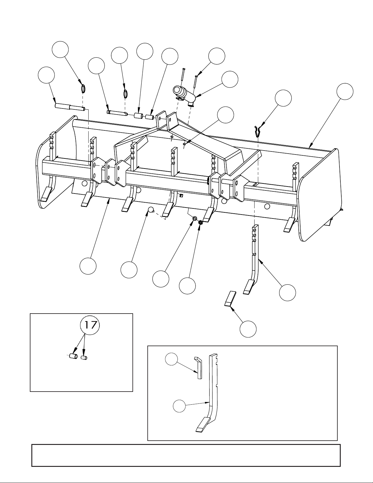
3
6
5
11
13
12
10
8
16
15
1
14
7
2
4
3
9
NYLON INSERT LOCK NUT, 5/16"
2
P-BOLT 5/8" X 1 3/4" GR. 5
16
T-24
LOCK WASHER, 5/8"
16
T-22
HEX NUT, 5/8"
16
Figure 1
8A
7A
PART NUMBER
DESCRIPTION
QTY.
14834
SCARIFIER SHANK
1
10697
SCARIFIER POINT
1
15281 1
Set of Lower Hitch
Bushings for iMatch
(Sold Separately)
Part # 5TL14834 & # 5TL15281
Used on units prior to
Serial #XFBB32X000153
13 Parts Catalog

Parts List (cont’d)
Ref.# Part # Description Qty.
1 5TL15259
5TL15260
5TL15261
2 5TL13257 CAT. 1 & 2 HITCH PIN 2
3 5TLVP252 LYNCH PIN 3
4 5TL15206 CAT. 1 TOP LINK PIN, 3 7/8" USABLE LENGTH 1
5 5TL15209 CAT. 1 BUSHING, 1 15/16" 1
6 5TL15210 CAT. 2 BUSHING, 1 15/16" 1
7 5TL15413 SHANK RETAINER CLIP *MS
7A 5TL15281 SHANK KEY *MS
8 5TL14835F SCARIFIER SHANK WITH WELD ON POINT *MS
8A 5TL14834 SCARIFIER SHANK WITH WELD ON POINT *MS
9 5TL10697 SCARIFIER POINT ONLY *MS
10 5TL10704
5TL10705
5TL10706
11 5TL15189 ASSEMBLY MANUAL TUBE AND CAP 1
12 5TL15287 HEX BOLT, 5/16" X 3" GR. 2 2
13 5TL15198 NYLON INSERT LOCK NUT, 5/16" 2
14 5TL10699 PLOW BOLT, 5/8" X 1 3/4" *MS
15 5TLT24 5/8" LOCKWASHER *MS
16 5TLT22 5/8" HEX NUT *MS
17 5TL15638 SET OF LOWER HITCH BUSHINGS FOR IMATCH N/A
5TL15288 BB32 ASSEMBLY MANUAL (NOT SHOWN) 1
5TL15282 MODEL BB3272 DECAL (NOT SHOWN) 1
5TL15283 MODEL BB3284 DECAL (NOT SHOWN) 1
5TL15284 MODEL BB3296 DECAL (NOT SHOWN) 1
5TL15285 3 1/3" FRONTIER LOGO DECAL (NOT SHOWN) 2
5TL15286 SAFETY DECAL SHEET (incl. 4 decals)(NOT SHOWN) 1
5TL15199 9” RED REFLECTOR (NOT SHOWN) 2
5TL15200 9” YELLOW REFLECTOR (NOT SHOWN) 2
MAIN BOX WELDMENT MODEL BB3272
MAIN BOX WELDMENT MODEL BB3284
MAIN BOX WELDMENT MODEL BB3296
CUTTING EDGE, 72" MODEL BB3272
CUTTING EDGE, 84" MODEL BB3284
CUTTING EDGE, 96" MODEL BB3284
1
1
1
2
2
2
* M/S - Model Specific Parts Catalog 14

Bolt Size Chart
SAE Torque Chart
15 Bolt Size and Bolt Torque Chart

Notes
Notes 16

PART NO.
5TL15288
© 2010 Monroe Tufline Manufacturing, Inc. All Rights Reserved
 Loading...