


The Impact of Shading on
a PV System
Whitepaper
Information class: Public, Fronius International

The Impact of Shading on a PV System
2/33
© Fronius International GmbH
Version 01 02/2023
Business Unit Solar Energy

The Impact of Shading on a PV System
3/33
Fronius reserves all rights, in particular rights of reproduction, distribution and translation.
No part of this work may be reproduced in any way without the written consent of Fronius. It must not
be saved, edited, reproduced or distributed using any electrical or electronic system.
Please note that the information published in this document is subject to change, despite our
exercising utmost care in its preparation, and that neither the author nor Fronius assume any legal
liability.

The Impact of Shading on a PV System
4/33
Table of Contents
1
Objective ................................................................................................................................... 5
2 Introduction ............................................................................................................................. 6
3 Behavior of bypass diodes in shaded and unshaded PV modules ...................................... 7
3.1 Bypass diodes ....................................................................................................................................... 7
3.2 Behavior of unshaded/shaded PV modules ..................................................................................... 7
3.3 Practical example ................................................................................................................................. 9
4 Maximum Power Point Tracking .......................................................................................... 11
4.1 Dynamic Peak Manager ..................................................................................................................... 13
5 DC Optimizers ......................................................................................................................... 14
6 Practice examples .................................................................................................................. 16
6.1 PV SOL .................................................................................................................................................. 16
6.2 Configuration ...................................................................................................................................... 16
6.3 Results .................................................................................................................................................. 17
6.3.1 Shading from a chimney ................................................................................................................... 17
6.3.2 Shading from an antenna ................................................................................................................. 20
6.3.3 Shading from a tree ........................................................................................................................... 22
6.3.4 Shading from another house ........................................................................................................... 25
6.3.5 Shading from a pillar ......................................................................................................................... 28
7 Conclusion ............................................................................................................................... 32
8 References .............................................................................................................................. 33

The Impact of Shading on a PV System
5/33
1 Objective
The objective of this whitepaper is to show how Fronius inverters, all with integrated Dynamic Peak
Manager can be used to minimize yield losses in partially shaded PV systems – without the use of DC
optimizers that offer no significant yield advantages. With current electricity prices, many PV Systems
are no longer dimensioned to match electricity consumption and instead the aim is to install the
maximum kWp that fits the roof. For this reason, shaded areas on the roof are also used. Customers are
then often unsure if the shading management of a classic string inverter is sufficient or if additional
components like DC optimizers are needed. With Fronius Dynamic Peak Manager, the highest yields can
be achieved even when there is partial shading.

The Impact of Shading on a PV System
6/33
2 Introduction
The performance of a photovoltaic (PV) system depends not only on solar irradiance and temperature
but also on shading and configuration. Shading can be one of the main causes for losses in PV systems,
reducing overall production. It also leads to the loss of energy conversion and causes nonlinearity on
the I-V characteristics. Under normal conditions, sunlight is uniformly distributed over the PV modules
and the characteristic power-voltage curve has a single maximum power point at which the highest
power can be extracted. Due to the presence of shading – which can be caused by clouds, trees, nearby
buildings, other modules, module dust or various objects – PV modules may not receive an equal
amount of solar irradiance. The impact of shading will depend on the number of shaded cells. When a
single cell is shaded, the current or voltage through the substring is reduced and the shaded cells can
become reverse biased. They consume power instead of generating it, leading to reduced power
generation. An intelligent system design and efficient shade management are therefore essential to
achieving the best possible operation of a shaded PV system. Shading not only causes a decrease in
power output but also may cause hotspots to occur as a result of the increased mismatch between PV
modules. In extreme cases of shading, the reverse bias on the solar cell can exceed its breakdown
voltage and cause irreparable damage. To protect the modules from this, bypass diodes are included
on every module to bypass the shaded PV cell or module.

The Impact of Shading on a PV System
7/33
3 Behavior of bypass diodes in shaded and unshaded PV modules
Figure 1: Standard PV module with no shading
This chapter describes the behavior of bypass diodes and PV modules in shaded and unshaded
conditions. A scenario is presented in which the inverter – the active component – is activating the
bypass diode in order to achieve a higher yield.
3.1 Bypass diodes
Bypass diodes are part of every crystalline PV module. The bypass diodes are connected in parallel but
with opposite polarity to a PV cell and have no effect on the PV module output when they are not
activated. A standard PV module with 60 cells is built with 3 substrings, wherein each substring has 20
cells and is protected by a bypass diode. Many commercial PV cell modules have integrated the bypass
diode into the module junction box. The bypass diodes are used in PV modules to prevent the
application of high reverse voltage and to allow the current to “skip over” the shaded cells of the PV
module. The purpose is to allow the module current to bypass shaded or broken cells to prevent hot
spot or hot cell damage resulting from reverse voltage biasing from other cells in that module.
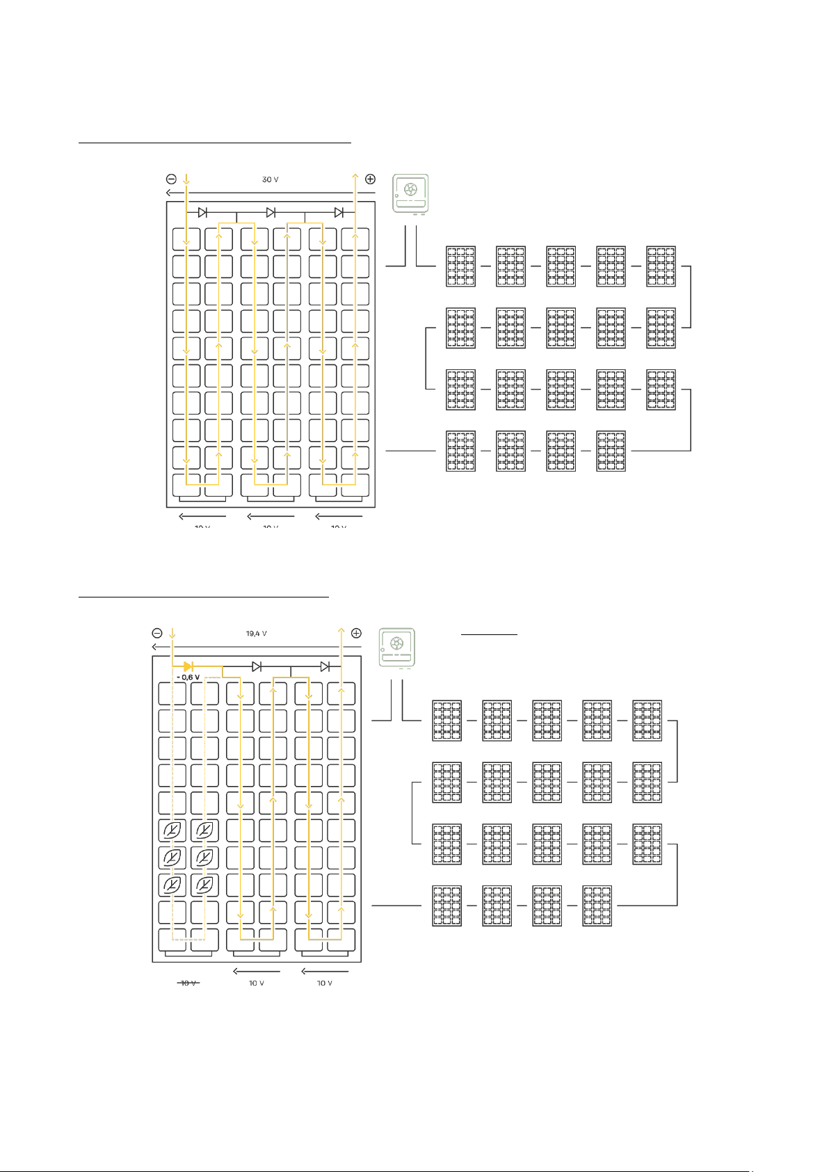
3.2 Behavior of unshaded/shaded PV modules
This is a standard PV module with 60 cells, where each PV
cell produces about 0.5V, each substring has 10V, and the
current for the PV module is up to 10A. Under normal
operating conditions, when there is no shadow, each PV
cell will be forward biased and the bypass diode will be
reverse biased, and the current will circulate through all
the cells. When all the cells are illuminated, the bypass
diode is blocked and the PV module will have 30V and 10A
across it.

The Impact of Shading on a PV System
8/33
Figure 2: Standard PV module with shading
Figure 3: Half-cut cell PV module with shading
If there is shading on one or more cells, the inverter can
control the voltage to make the bypass diode conductive.
This allows the full current to bypass the cells of the shaded
substring, protecting it from heating up and hotspotting.
The voltage at the bypass diode becomes negative and the
current passes through it.
In the shaded substring, the bypass diode is “activated”
with a voltage drop of approximately -0.6V. The second and
the third substring will have 10V each. This amounts to 19.4
V (V
module=Vstring1+Vstring2+Vstring3
= -0.6V+10V+10V) across the
entire PV module. As a result, the full current (e.g.10A) can
flow.
Half-cut cell PV modules can have an advantage, depending
on which part of the PV module is under shade and how
they are positioned. If they are positioned vertically and the
lower part of the half-cut PV module is under shade, the
remaining upper part still has a lot of power compared to
the full-size standard PV module, since the whole module is
lost in such cases and there is no power production. With
the half-cut cell PV module, 5A can in this case still flow
through each substring of the unshaded half, and the
voltage will be 10V through each substring, with a total
voltage of 30V. This provides a power output of 150W, which
is half of the PV module’s rated power. If the half-cut cell PV
module is positioned horizontally and the shading covers
1/3 of the PV module (from bottom to top or vice versa) then
there is no yield difference compared to a full-size, standard
PV module.
The Impact of Shading on a PV System
9/33
3.3 Practical example
Figure 4: PV system with 20 modules without shading
The inverter reduces the voltage to reach
System with 20 modules without shading:
System with 20 modules with shading:
19,4V on the shaded module. This makes the
bypass diode conductive.
Figure 5: PV system with 20 modules with shading

The Impact of Shading on a PV System
10/33
Let’s take as an example a system with 20 PV modules, each with 30V and 10A, connected in series to a
The bypass diode is simply a passive component and it changes something only if the inverter – the
Ideally, there will be no shading in the system, but this is unfortunately not the reality in many
string inverter. Normally, if we don’t have shading, the bypass diode is passive and is not conducting,
so it will not conduct current, and we will have 600V and 10A across the system with a power output of
6000W (Figure 4). Shading occurs when, for example, leaves fall on one of the modules (Figure 5). When
shading occurs, two things are possible:
1. The inverter will stay at 600V, since each substring will theoretically still produce 10V but not 10A
due to the shading, so that only a 3A current can pass in the first submodule and each
submodule will be limited to 3A current. In this case, the system output will be 1800W.
2. The inverter will reduce the voltage and make the bypass diode conductive. To be
conductive, the bypass diode needs a voltage in its forward direction. In this example the voltage
will be reduced from 600V to 589.4 V, and the bypass diode will be activated by the inverter with
a total voltage drop of -0.6V. In the shaded substring, the 10A string current will be diverted by
the bypass diode: 7A will pass through the bypass diode and 3A will pass through the shaded
and unshaded cells. A 10A current will circulate in the shaded substring, through the other
unshaded substrings and PV modules. In this case, when the inverter – the active component –
reduces the voltage, the system output is 5894 W, and the power output is higher compared to
the first option.
active component – does something (such as reducing the voltage) that leads the bypass diode to
react to the system conditions.
cases. When designing a system, we advise you to try to avoid shading in the times when irradiance
is above 500W/m
2
.
 Loading...