


/ Battery Charging Systems / Welding Technology / Solar Electronics
FRONIUS IG
15 / 20 / 30 / 40 / 60 / 60 HV
EN
Operating Instructions
Grid-connected inverters for photovoltaic systems
42,0410,0828 008-31032015

Dear Reader
Introduction |
Thank you for choosing Fronius - and congratulations on your new, technically high- |
|
grade Fronius product! This instruction manual will help you get to know your new |
|
machine. Read the manual carefully and you will soon be familiar with all the many |
|
great features of your new Fronius product. This really is the best way to get the most |
|
out of all the advantages that your machine has to offer. |
|
Please also take special note of the safety rules - and observe them! In this way, you |
|
will help to ensure more safety at your product location. And of course, if you treat your |
|
product carefully, this definitely helps to prolong its enduring quality and reliability - things |
|
which are both essential prerequisites for getting outstanding results. |
EN
ud_fr_st_et_00493 01/2012

Safety rules
DANGER!
WARNING!
CAUTION!
NOTE!
Important!
“DANGER!” indicates an imminently hazardous situation which, if not avoided, will result in death or serious injury. This signal word must be limited to the most extreme situations. This signal word is not used for hazards relating to property damage unless there is also a risk of personal injury appropriate to this level.
“WARNING!” indicates a potentially hazardous situation which, if not avoided, could result in death or serious injury. This signal word is not used for hazards relating to property damage unless there is also a risk of personal injury appropriate to this level.
“CAUTION!” indicates a potentially hazardous situation which, if not avoided, may result in minor or moderate injury. It may also be used to draw attention to unsafe practices that may cause damage to property.
“NOTE!” indicates a situation which implies a risk of impaired results and damage to the equipment.
“Important!” indicates practical hints and other particularly useful information. It is not a signal word for a harmful or dangerous situation.
Whenever you see any of the symbols shown above, pay close attention to the contents of the manual!
EN
General Remarks |
|
This equipment has been manufactured in accordance with the state of the |
|
||
|
|
art and general safety-engineering principles. Nevertheless, incorrect opera- |
|
|
tion or misuse may still endanger |
-the life and well-being of the operator or of third parties,
-the equipment and other tangible assets belonging to the owner/operator,
-working efficiently with the equipment.
All persons involved in any way with starting up, servicing and maintaining the equipment must
-be suitably qualified
-have good knowledge of dealing with electrical installations and
-read this instruction manual thoroughly and follow the instructions to the letter.
The instruction manual must be kept at the machine location at all times. In addition to the instruction manual, it is important to comply with both the generally applicable and local accident prevention and environmental protection regulations.
All the safety instructions and warning signs on the machine itself:
-must be kept in a legible condition
-must not be damaged, must not be removed
-must not be covered, pasted or painted over
I
ud_fr_se_sv_00923 022009

General Remarks |
For information about where the safety instructions and warning signs are |
(continued) |
located on the machine, please refer to the section of your machine’s in- |
|
struction manual headed “General Remarks”. |
|
Any malfunctions which might impair machine safety must be remedied |
|
immediately before the machine is switched on. |
|
Your safety is at stake! |
Utilisation for |
|
The machine may only be used for jobs as defined by the “intended purpose”. |
|
||
Intended Purpose |
|
|
Only |
|
Utilisation for any other purpose, or in any other manner, shall be deemed "not |
|
|
in accordance with the intended purpose". The manufacturer shall not be |
|
|
liable for any damage resulting from such improper use. |
|
|
Utilisation in accordance with the “intended purpose” also comprises |
|
|
- thorough reading of and compliance with all the instructions, safety in- |
|
|
structions and warnings given in this manual |
|
|
- performing all stipulated inspection and servicing work |
|
|
- installation in accordance with the instruction manual |
Where appropriate, the following guidelines should also be applied:
-regulations of the power supply company for input to the grid
-information provided by the manufacturer of the solar modules
Ambient |
|
Operation or storage of the machine outside the stipulated range is deemed |
|
||
Conditions |
|
“not in accordance with the intended use”. The manufacturer shall not be |
|
|
liable for any damage resulting therefrom. |
|
|
Please refer to the technical data in your instruction manual for accurate |
|
|
|
|
|
information about the permissible ambient conditions. |
Qualified Staff |
|
|
|
The servicing information provided in this instruction manual is only intended |
|
|
|
||
|
|
|
||
|
|
|
|
for qualified staff. An electric shock can be fatal. Please do not carry out any |
|
|
|
|
|
|
|
|
|
activities other than those referred to in the documentation. This also applies |
|
|
|
|
even if you are suitably qualified. |
All cables and other leads must be firmly attached, undamaged, properly insulated and adequately dimensioned. Have loose connections, scorched, damaged or under-dimensioned cables and wires repaired immediately by an authorised specialist company.
Maintenance and repair may only be carried out by an authorised specialist company.
There is no guarantee in the case of parts sourced from other suppliers that these parts have been designed and manufactured to cope with the stresses and safety requirements that will be placed on them. Use only original spare parts (this also applies to standard parts).
Do not carry out any alterations, installations or modifications to the machine without first getting the manufacturer’s permission.
Replace immediately any components that are not in perfect condition.
ud_fr_se_sv_00923 022009
II
Safety Precautions at the Machine Location
Information on noise emission values
EMC device classifications
EMC measures
Ensure when installing machines with cooling-air vents that the cooling air can flow freely through the air vents without obstruction. Only operate the machine with the degree of protection specified on the rating plate.
The inverter generates a maximum sound power level of <80 dB(A) (ref. 1pW) when operating under full load in accordance with IEC 62109-1.
The device is cooled as quietly as possible with the aid of an electronic temperature control system, and depends on the amount of converted power, the ambient temperature, the level of soiling of the device, etc.
It is not possible to provide a workplace-related emission value for this device because the actual sound pressure level is heavily influenced by the installation situation, the power quality, the surrounding walls and the properties of the room in general.
Devices with emission class A:
-are only designed for use in an industrial setting
- can cause conducted and emitted interference in other areas.
Devices with emission class B:
-satisfy the emissions criteria for residential and industrial areas. This also applies to residential areas in which power is supplied from the public low-voltage grid.
EMC device classification as per the rating plate or technical specifications
In certain cases, even though a device complies with the standard limit values for emissions, it may affect the application area for which it was designed (e.g. when there is sensitive equipment at the same location, or if the site where the device is installed is close to either radio or television receivers).
If this is the case, then the operator is obliged to take appropriate action to rectify the situation.
EN
Mains connection |
|
|
|
|
|
High-performance devices (> 16 A) can affect the voltage quality on the mains |
|
|
|
|
|
||
|
|
|
|
|
|
network because they can feed powerful current into the main supply. |
|
|
|
|
|
|
|
|
|
|
|
|
|
This may affect a number of types of device in terms of: |
|
|
|
|
|
|
|
|
|
|
|
|
|
- connection restrictions |
|
|
|
|
|
|
|
|
|
|
|
|
|
- criteria with regard to maximum permissible mains impedance *) |
|
|
|
|
|
|
- criteria with regard to minimum short-circuit power requirement *) |
*) |
at the interface with the public mains network |
|
|
see Technical Data |
|
In this case, the plant operator or the person using the device should check whether or not the device is allowed to be connected, where appropriate through discussion with the power supply company.
III
ud_fr_se_sv_00923 022009

Electrical Installa- |
|
|
|
Electrical installations may only be executed in accordance with the relevant |
||
|
|
|
||||
tions |
|
|
|
national and regional standards and specifications. |
||
ESD Protective |
|
|
|
Danger of damage to electronic components due to electrostatic discharge. |
||
|
|
|
||||
|
|
|
||||
Measures |
|
|
|
Take appropriate protective measures when replacing and installing the |
||
|
|
|
|
|
|
components. |
Safety Precau- |
|
|
|
Only operate the machine if all its protective features are fully functional. If |
||
|
|
|
||||
|
|
|
||||
tions in Normal |
|
|
|
any of the protective features are not fully functional, there is a danger to: |
||
Operation |
|
|
|
- the life and well-being of the operator or other persons |
||
|
|
|
|
|
|
- the equipment and other tangible assets belonging to the owner/operator |
|
|
|
|
|
|
- working efficiently with the equipment. |
|
|
|
|
|
|
Have any safety features that are not fully functional repaired by an autho- |
|
|
|
|
|
|
rised specialist company before switching the machine on again. |
|
|
|
|
|
|
Never bypass or disable safety features. |
Safety markings |
|
|
|
Equipment with the CE mark fulfils the basic requirements of the Guideline |
||
|
|
|
||||
|
|
|
|
|
|
Governing Low-Voltage and Electromagnetic Compatibility. (More detailed |
|
|
|
|
|
|
information about this may be found in the Annex or in the section of your |
Disposal |
|
|
|
|
documentation headed “Technical Data”.) |
|
|
|
|
|
Do not dispose of this device with normal domestic waste! |
||
|
|
|
|
|||
|
|
|
|
|
|
To comply with the European Directive 2002/96/EC on Waste Electrical and |
|
|
|
|
|
|
Electronic Equipment and its implementation as national law, electrical |
|
|
|
|
|
|
equipment that has reached the end of its life must be collected separately |
|
|
|
|
|
|
|
|
|
|
|
|
|
and returned to an approved recycling facility Any device that you no longer |
|
|
|
|
|
|
require must be returned to our agent, or find out about the approved collec- |
|
|
|
|
|
|
tion and recycling facilities in your area. |
|
|
|
|
|
|
Ignoring this European Directive may have potentially adverse affects on the |
|
|
|
|
|
|
environment and your health! |
Data security |
|
|
|
The user is responsible for backing up data relating to changes made to |
||
|
|
|
||||
|
|
|
|
|
|
factory settings. The manufacturer will not accept liability if personal settings |
|
|
|
|
|
|
are deleted. |
Copyright |
|
|
|
|
|
Copyright to this instruction manual remains the property of the |
|
|
|
|
|
||
|
|
|
|
|
||
|
|
|
|
|
|
manufacturer. |
|
|
|
|
|
|
The text and illustrations are all technically correct at the time of going to |
|
|
|
|
|
|
print. The right to make modifications is reserved. The contents of the |
|
|
|
|
|
|
instruction manual shall not provide the basis for any claims whatever on the |
|
|
|
|
|
|
part of the purchaser. We should be most grateful for your comments if you |
|
|
|
|
|
|
have any suggestions for improvement, or can point out to us any mistakes |
|
|
|
|
|
|
which you may have found in the manual. |
ud_fr_se_sv_00923 022009
IV

Table of Contents |
|
Safety of persons ................................................................................................................... |
4 |
Safety ............................................................................................................................ |
4 |
Housing unit .................................................................................................................. |
4 |
Galvanic insulation ........................................................................................................ |
4 |
Monitoring the electrical mains network ........................................................................ |
4 |
Photovoltaic generator .................................................................................................. |
5 |
Mains connection .......................................................................................................... |
5 |
DC plugs ....................................................................................................................... |
5 |
AC plugs ....................................................................................................................... |
5 |
The Safety Concept ............................................................................................................... |
6 |
Standards and Regulations ........................................................................................... |
6 |
Conformity Declaration ................................................................................................. |
6 |
General Introduction ............................................................................................................... |
7 |
How a photovoltaic system works ..................................................................................... |
7 |
General information ...................................................................................................... |
7 |
Your roof is your power generator ................................................................................. |
7 |
Electricity is converted under the roof ........................................................................... |
8 |
The FRONIUS IG Unit in the Photovoltaic System ........................................................... |
9 |
General information ...................................................................................................... |
9 |
Transforming DC into AC electricity .............................................................................. |
9 |
Fully automatic operation management ........................................................................ |
9 |
Voltage transformation and galvanic insulation ............................................................. |
9 |
Monitoring the mains network ..................................................................................... |
10 |
Display function and data communication .................................................................. |
10 |
Your advantage ............................................................................................................ |
11 |
Product description .............................................................................................................. |
12 |
The FRONIUS IG Unit ..................................................................................................... |
12 |
How it functions........................................................................................................... |
12 |
Startup phase .............................................................................................................. |
12 |
Overview for FRONIUS IG (for indoor housing) ......................................................... |
14 |
Overview for FRONIUS IG Outdoors .......................................................................... |
15 |
LED for operating status ............................................................................................. |
16 |
Operating scheme ................................................................................................................ |
18 |
The Display ..................................................................................................................... |
18 |
General information .................................................................................................... |
18 |
Functions of the keys .................................................................................................. |
18 |
Symbols ...................................................................................................................... |
18 |
Navigating in the Display ................................................................................................. |
19 |
Display illumination ..................................................................................................... |
19 |
Menu level................................................................................................................... |
20 |
Select display mode .................................................................................................... |
20 |
Scrolling between display functions ............................................................................ |
21 |
EN
1
Display Modes ................................................................................................................. |
21 |
Scheme of display modes ........................................................................................... |
21 |
Scheme of display readings ........................................................................................ |
22 |
Display mode „Now“ .................................................................................................... |
23 |
Display mode „Day / Year / Total“ ................................................................................ |
26 |
The Setup Menu.............................................................................................................. |
29 |
List of menu items ....................................................................................................... |
29 |
Display mode „Setup“ ................................................................................................. |
30 |
Enter the setup menu ................................................................................................. |
30 |
Scroll among menu items ........................................................................................... |
30 |
Setting the menu items ............................................................................................... |
31 |
Additional information........................................................................................................... |
41 |
Upgrading the system ................................................................................................. |
41 |
Forced ventilation........................................................................................................ |
42 |
Installation manual ............................................................................................................. |
43 |
Open the housing ................................................................................................................. |
44 |
FRONIUS IG (installation of the indoor housing) ........................................................ |
44 |
FRONIUS IG Outdoors ............................................................................................... |
45 |
Installation ............................................................................................................................ |
46 |
Choosing the location general .................................................................................... |
46 |
Choosing the location - indoor housing ....................................................................... |
46 |
Choosing the location - outdoor housing..................................................................... |
47 |
Fixing the wall mounting frame for indoor housing...................................................... |
48 |
Fixing the wall mounting frame for FRONIUS IG Outdoors ....................................... |
49 |
Connection ........................................................................................................................... |
52 |
Connection to the Solar Modules and to the Public Mains .............................................. |
52 |
Solar modules ............................................................................................................. |
52 |
Mains network monitoring ........................................................................................... |
52 |
Schemes with more than one inverter ........................................................................ |
52 |
AC-side overcurrent protection ................................................................................... |
53 |
Connection alternatives .............................................................................................. |
53 |
1. Terminal block ......................................................................................................... |
53 |
2. DC plug ................................................................................................................... |
54 |
3. AC plug connection and DC plug ............................................................................ |
55 |
4. FRONIUS IG Outdoors ........................................................................................... |
57 |
Start up Operation ................................................................................................................ |
59 |
Configuring your Inverter ................................................................................................. |
59 |
Factory pre-set configuration ...................................................................................... |
59 |
Your personal configuration ........................................................................................ |
59 |
LocalNet ............................................................................................................................... |
60 |
System upgrading /slot-in board system ..................................................................... |
60 |
Data recorder .............................................................................................................. |
60 |
COM Card ................................................................................................................... |
60 |
Insert slot-in boards, FRONIUS IG (Installation for indoor housing) ........................... |
61 |
2
Configuration............................................................................................................... |
62 |
Example ...................................................................................................................... |
62 |
Status diagnosis and repair .................................................................................................. |
64 |
Service-Codes Displayed ................................................................................................ |
64 |
Service display ............................................................................................................ |
64 |
General service codes ................................................................................................ |
64 |
Complete failure .......................................................................................................... |
65 |
FRONIUS IG with several power stage sets ............................................................... |
65 |
Class 1 ........................................................................................................................ |
66 |
Class 2 ........................................................................................................................ |
67 |
Class 3 ........................................................................................................................ |
68 |
Class 4 ........................................................................................................................ |
69 |
Class 5 ........................................................................................................................ |
71 |
Customer service ........................................................................................................ |
72 |
Annex ................................................................................................................................... |
73 |
Technical Data................................................................................................................. |
73 |
Fronius IG 15 / 20 / 30 ................................................................................................ |
73 |
Fronius IG 40 / 60 / 60 HV .......................................................................................... |
74 |
Our product complies with the following standards and regulations ........................... |
75 |
Warranty and Liability ....................................................................................................... |
76 |
Fronius manufacturer's warranty ................................................................................... |
76 |
Maintenance and disposal of obsolete equipment ............................................................ |
76 |
Maintenance ................................................................................................................ |
76 |
Recycling ..................................................................................................................... |
76 |
EC-Declaration of conformity ................................................................................................ |
77 |
EN
3

Safety of persons
Safety |
|
Warning! Incorrect operation and work performed incorrectly can |
|
|
cause serious injury & damage! Only qualified staff are authorized to |
|
put your FRONIUS IG unit into operation and only within the scope |
|
of the respective technical regulations. Do not start operation or |
|
carry out maintenance works before you have read the chapter |
|
„Safety Conditions“! |
Housing unit Only qualified installers are authorized to open the connection area.
Opening the connection area is only permitted when it is not under voltage.
The separately insulation encased power stage shall only be opened when not under voltage and only by Fronius-trained service staff.
Galvanic insu- The design and function of the FRONIUS IG unit offer a maximum of safety, lation both during installation as well as in operation. A complete galvanic insulati-
on between DC and AC side guarantees maximum safety.
The FRONIUS IG takes over the tasks of galvanic insulation and network monitoring. The passive and active measures for the protection of persons and equipment are understood by this.
Monitoring the Whenever conditions in the electric mains network are inconsistent with
electrical |
standard conditions (for example mains switch-off, interruption), your |
mains net- |
FRONIUS IG unit will immediately stop operating and interrupt the supply |
work |
of power into the mains. |
Your FRONIUS IG unit can monitor the situation in the mains in several ways, by
-monitoring voltage
-monitoring cycle frequency
-ENS (optional)
The ENS option is compulsory in only a few countries, and only for them the FRONIUS IG unit is available with this option. In any case however will the monitoring and safety systems integrated in the FRONIUS IG unit be available as standard equipment.
4

Monitoring the |
The permanent ENS mains monitoring scheme is an additional link in its |
electric mains |
safety chain. One of the signs by which ENS identifies abnormal situati- |
network |
ons in the mains is a sudden increase of the impedance in the mains |
(continued) |
network. |
|
Both the permanent mains monitoring by your FRONIUS IG unit directly |
|
as well as ENS make sure that in case of a mains blackout (due to being |
|
switched off by the utility company or due to a defect in the transmission |
|
line) it stops feeding power into the mains. |
|
This scheme definitely prevents dangerous voltages at the AC lines and |
|
constitutes an essential contribution towards avoiding hazards for the |
|
maintenance staff. |
Photovoltaic |
Before connecting the solar modules, you must check whether the voltage |
generator |
parameters laid down in the manufacturer’s data correspond with reality. |
|
When checking the voltage reading, please take into account that solar |
|
modules supply a higher no-load voltage when temperatures are low and |
|
insolation remains unchanged. |
|
At an outside temperature of -10 degrees centigrade the no-load voltage |
|
of the solar modules must in no case exceed 500 V - or 530 V for the IG |
|
60 HV. The data sheet of the solar module will tell you the temperature |
|
factors applicable for ascertaining the theoretical no-load voltage at -10 |
|
degrees centigrade. |
|
In case the solar modules exceed a no-load voltage of 500 V - or 530 V |
|
for the IG 60 HV - the FRONIUS IG unit will be completely damaged and |
|
all warranty rights will cease to exist. |
Mains connec- |
Only a licenced electricity installer is authorized to carry out the connec- |
tion |
tion works to the public mains network. |
DC plugs |
Note! If DC plugs are provided, they must never be disconnected |
|
from the sockets of the solar modules as long as the FRONIUS IG |
|
unit is feeding power into the mains. Before disconnecting the DC |
|
plug you must always disconnect in the fuse for the house distribu- |
|
tion. |
AC plugs |
Note! Disconnect AC plug connections only when the equipment |
|
is not under voltage, after having disconnected the fuse for the in- |
|
house distribution panel. |
EN
5
The Safety Concept
Standards and Your FRONIUS IG unit complies with all applicable standards and regula-
Regulations tions.
They comprise in particular:
-Guideline 89/336/EEC electromagnetic compatibility
-Guideline 93/68/EEC CE-marking
-European standards EN 50 081-1, EN 50 082-2, EN 61 000-3-2
-„Guideline for parallel operation of self-owned photovoltaic generating systems with the low voltage mains network of the utility supply company“, issued by the Association of German Electric Utility Supply Companies (VDEW)
-„Technical Guidelines for parallel operation of self-owned photovoltaic generating systems with the low voltage mains network of the utility supply company“, issued by the Association of Electric Utility Supply Companies of Austria
-„Safety requirements for photovoltaic energy generation plants“ (ÖNORM/ÖVE E2750), to the extent that these regulations are applicable for the inverter.
Conformity The respective conformity declarations you will find in the appendix to
Declaration these operating instructions.
6

General Introduction
How a photovoltaic system works
General infor- The energy from worldwide insolation amounts to a total of about mation 1,540,000,000,000,000,000 kWh/year (1,540 Peta kWh/year). This is
15.000 times as much as the electricity consumption worldwide. We congratulate you on your decision to actively use world’s biggest energy pool. By the way, it was a scientist in the field of of physics, Alexandre-
Edmond Bequerel, who first discovered the photo-voltaic effect in 1839.
The name photo-voltaic comes from the driving force behind this technology, which is the ray of light. The ray of light consists of unimaginably tiny particles, the photons.
Your roof is your power generator
Let us simply start our explanation with a straight silicon solar cell. Remembering our physics class in school, we know that there are four electrons in the outside electron shell of a silicon atom arranged around its atomic nucleus, they are the so-called peripheral valency electrons. The sunlight’s photons enter the solar cells and concentrate energy in the valency electrons. The electron eventually separates from the silicon atom and leaves behind it an atom with a positive charge.
So that the free electrons will flow in one direction and thus generate electricity, the poles on the front and back side of the cell must be different from each other.
The silicon atoms of the front must be packed with a slight quantity of phosphor atoms which contain an additional valency electron. On the back of the cell, atoms of boron having only three valency electrons are added to the silicon atoms.
The result is an imbalance which makes the electrons flow, and this is how electric power is generated.
Many such solar cells united together and packed behind glass form one of your solar modules.
EN
7

Your roof is |
|
|
|
|
|
|
|
|
+ |
|
|
|
|
|
|
||
your power |
|
|
|
|
|
|
tension |
|
|
|
|
|
|
|
|
||
generator |
|
|
|
|
|
|
|
|
(continued) |
|
string |
|
mod. 1 |
tension |
|
||
|
|
|
||||||
|
|
|
|
|
|
|
||
|
|
|
|
|
|
|
||
|
|
|
mod. 2 |
|
||||
|
|
|
|
|
|
|||
|
|
|
|
|
|
|
tension |
|
|
|
|
|
|
|
|
||
|
|
|
|
|
|
|
|
|
|
|
|
|
mod. n |
|
|||
|
- |
|
|
|
|
|
|
|
|
|
|
|
|
|
|
|
|
|
|
|
|
|
|
|
|
|
|
+ |
|
|
|
|
|
|
|
|
string 1 |
|
|
|
string 2 |
|
|
|
|
|
|
|
|
|
|
||
|
|
mod. 1 mod. 2 |
||||||
-
module 1 |
|
module 2 |
string tension |
3 |
total |
module |
|
|
|
|
|
|
... n |
string 3 |
|
= |
|
mod. n |
stringtotaltension |
tensionmodule2,1, |
|
|
|
||
|
|
|
|
|
|
|
|
Power output and voltage are increased by combining a number of solar cells. If solar modules are connected in series like on a string, both the output potential as well as the voltage will increase.
In a parallel connection of several such strings the potential output and the modular electric power will increase, while the voltage will remain unchanged. The total of all solar modules connected parallel and in series is called solar generator.
Electricity is |
The direct current generated in the solar modules can be fed into the |
converted |
public mains network or put to home use after having been transformed in |
under the roof |
an inverter. |
|
This is the basic purpose of your FRONIUS IG unit. |
8

The FRONIUS IG Unit in the Photovoltaic System
General infor- Your FRONIUS IG unit is the latest generation of solar inverters. It is the mation highly complex link between solar modules and the public electricity
mains network.
As such it is in charge of a number of highly qualified tasks.
Transforming The FRONIUS IG unit transforms the direct current generated by the solar DC into AC modules into alternating current. This alternating current is fed into your electricity home system or into the public mains synchronically with the voltage
which is used there. The FRONIUS IG has been designed exclusively for use in mains connected photovoltaic schemes. It cannot generate electric power independent from the public mains network.
Fully automa- The operation of the FRONIUS IG unit is fully automatic. Starting with tic operation sunrise, as soon as the solar modules generate enough power, the auto- management matic control unit starts monitoring voltage and frequency. As soon as
there is a sufficient level of insolation, your solar inverter starts supplying and feeding power. A few Watts of solar power output are sufficient to achieve this, depending on which version the unit is!
The operation of the FRONIUS IG unit ensures that at any time the maximum possible power output is drawn from the solar modules.
This function is called MPPT (Maximum Power Point Tracking). It operates with extremely high precision. As dusk starts there is no more sufficient energy available to feed power into the mains, the FRONIUS IG unit shuts the mains connection completely and stops operating. All settings and data recorded are of course saved.
Voltage trans- The FRONIUS IG has been designed for use with solar modules of a wide formation and range of input voltages. This allows the use of the greatest variety of galvanic insu- types of solar modules. Important notice: the parameters indicated for lation maximum DC voltage (total voltage of the solar cells connected) must at
no time be exceeded!
By its design and operation, the FRONIUS IG offers a maximum of safety during installation as well as in operation.
EN
9
Voltage trans- |
The FRONIUS IG is equipped with an HF-transformer (HF = high frequen- |
formation and |
cy) which assures a galvanic insulation between the DC side and the |
galvanic insu- |
mains. In addition, the HF principle results in a drastic reduction of the |
lation |
transformer’s size, which means that it requires less space and has consi- |
(continued) |
derably less weight. In spite of its full galvanic insulation, the FRONIUS IG |
|
unit achieves a high degree of efficiency, due to its innovative circuit |
|
schemes. |
Monitoring the The FRONIUS IG unit is in charge of monitoring the mains network. This mains network responsibility comprises all measures necessary for the protection of
persons and machines in case of a power blackout.
The FRONIUS IG unit is programmed to stop operation immediately and stop supplying power whenever conditions in the mains network deviate from standard (for example when power is switched off or in case of any other kind of interruption).
There are several ways how the FRONIUS IG unit can identify a mainscutoff, it can do so for example by monitoring:
-voltage
-frequency
-resistance (only FRONIUS IG with ENS)
For this purpose it is important that the specific monitoring procedures applicable for the respective countries are carried out directly by the FRONIUS IG unit without the use of additional electronic monitoring devices. This will result in a substantial reduction of the installation work and cost.
Display func- |
The complex technical systems of innovative solar inverters make it ne- |
tion and data |
cessary to design the display which is the interface with the user very |
communicati- |
carefully. It is an unwavering design aiming at ease of operation and |
on |
permanent availability of the system’s data. |
The FRONIUS IG unit is equipped with a basic recording function for monitoring minimum and maximum data on a daily and a cumulative basis directly from the display. There is also an option to allow the reading of the following weather data on the display:
-two different temperature readings (for example temperature at the solar modules as well as the outside temperature in the shade)
-insolation
In additition to the functions installed in the FRONIUS IG unit, a wide choice of elements offered for data communication allows for many possibilities of recording and visualising data. The respective components required to upgrade the system are easy to install using the FRONIUS IG DatCom operating instructions. The installation of system upgrades, such as DatCom components, allows for possible remote system monitoring
10

Display func- via modem, text messages to mobile phones in the event of faults, data tion and data visualisation and data comparison on the PC.
communication
(continued)
EN
Your advan- With each additional task, as described above and controlled directly by tage the inverter, installation becomes easier and less costly because no addi-
tional peripheral equipment will be required. Based on our experience and the use of the most innovative technologies, the FRONIUS IG unit is able to manage all these tasks simultaneously.
In addition, the FRONIUS IG unit complies with a whole number of requirements established for the safety of people and other household appliances, as well for its own safety.
Some of these requirements are:
-ability to monitor the mains network
-the quality of the electricity supplied
-detection of outside disturbance and interference (for example mobile telephones).
Annexed you will find the respective certificates.
11
Product description
The FRONIUS IG Unit
How it functions
Startup phase
The FRONIUS IG unit is designed for fully automatic operation. Basically no personal control is necessary for feeding the power it generates into the mains network.
The FRONIUS IG unit starts operating automatically as soon as the solar modules produce sufficient power output after sunrise. From this point onwards, you will also receive system information from the FRONIUS AG graphic display.
During its operation the FRONIUS IG unit maintains the voltage of the solar modules at any time within the range of optimal power withdrawal.
-the optimal voltage for any particular status of operation of the solar modules is called MPP voltage (MPP = maximum power point)
-exactly maintaining the MPP voltage guarantees an optimal level of the efficiency factor of your solar modules at any time (MPP-tracking).
As soon as dusk begins there is no more sufficient energy available to feed into the mains network, the FRONIUS IG unit fully shuts off the mains connection.
-during the night the FRONIUS IG unit does not draw any energy from the public mains
-the data and parameters set remain available
-it is also possible to shut the unit off manually
After having switched on automatically, the FRONIUS IG unit goes through a self-test, and after that through a test of the public mains network.
This test takes between only few seconds up to several minutes, depending on the regulations in your country. During startup the LED illumination is yellow.
(1)Segment test
-all display elements light up for about one second
(2)TEST
-self test of important components of the FRONIUS IG unit
-The FRONIUS IG unit goes through a master check list for a period of only a few seconds
-the display says „TEST“ and indicates the respective component which is being tested (for example „LED“)
12
Startup phase
(continued)
(3)Synchronisation with mains
-The screen displays „SYN-
CAC“
-„WAITPS“ is displayed: The
FRONIUS IG is waiting for all power supplies in the network to be on stand-by. This procedure takes place dependent on the DC-voltage.
-„SYNCAC“ is displayed subsequently.
(4)Startup test
-Before the FRONIUS IG unit starts supplying power into the mains, the conditions of the mains network are tested in detail in accordance with the regulations of your country.
-the screen displays „STARTUP“
Depending on the regulations of each country, the startup test can take between just a few seconds up to several minutes. The time elapsed is indicated by a bar shrinking from top down.
Whenever two scale divisions stop flashing and disappear, 1/10 of the total duration of the test is over
(5)Synchronisation ENS (option)
-if the FRONIUS IG unit is equipped with the ENS option, every detail of the ENS will be tested and synchronized
-the screen displays „SYNCENS“
Depending on the operating status of the ENS, test and synchronization may take up to several seconds.
(6)Operation of feeding power supply into the mains network
-After termination of the tests, the FRONIUS IG unit starts feeding power into the mains network.
-The LED lights up green, and the FRONIUS IG unit starts operating
EN
13

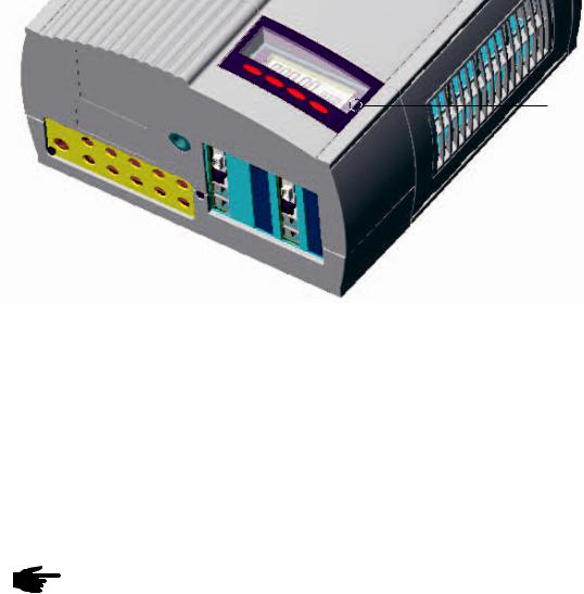
Overview for FRONIUS IG (for indoor housing)
(1)storage area for operation and installation manual
(2)ventilation grill
(3)LED for operation status
(4)display
(5)keyboard
(6)slot -in board area
(7)various versions of connection plate
(8)connection area - to be opened only by licensed electricity installers
(9)power stage, separately insulation encased - to be opened only by
Fronius trained service staff

 (1)
(1)


(9)

(8)
|
(2) |
|
(3) |
|
(4) |
(7) |
(5) |
|
(6) |
14

Overview for
FRONIUS IG
Outdoors (1)
(2)
(8) |
(2) |
(1)
|
|
|
|
|
|
|
(3) |
|
|
|
|
|
|
|
|
|
|
|
|
|
|
|
(4) |
|
|
|
|
|
|
|
|
(1) |
(7) |
(6) |
|
|
|
(5) |
|
|
|
|
|||||
(1)tightening screws for housing
(2)cooling bonnets
(3)LED for operation status
(4)display outside
(5)keyboard outside
(6)covering for AC connection and slot-in board area
(7)connection rail Multicontact
(8)cover slide to protect the buttons and the display from the sun’s rays.
Note! We recommend that the cover slide is pushed in front of the display in cases of direct sunshine.
EN
15
LED for operating status
LED
Depending on the operating status, the LED assumes different colours
(1)LED lights up green:
-a green light starts as soon as the FRONIUS IG unit has completed the startup phase, it stays green as long as the operation of feeding power into the network continues
-it indicates faultless operation of the photovoltaic equipment
(2)LED flashes green:
-as long as the photovoltaic equipment is operating without fault
-and an additional message is displayed on the screen
Note! A message appears for example if there is an insulation fault, which however does not affect the function of the FRONIUS IG. However for safety reasons we recommend that the insulation fault is remedied as soon as possible.
Depending on the country setup, the inverter can also disconnect from the public grid when there is an insulation error and stop feeding energy into the grid.
The FRONIUS IG with display shows a status message. A message is displayed in the FRONIUS IG.access software for the FRONIUS IG without display.
If a message (e.g. „502“, Section „Status diagnosis and remedy) is shown, rectify the relevant status and acknowledge this by pressing the „Enter“ button.
(3)LED lights up orange:
-The FRONUS IG unit will enter the automatic startup-phase, as soon as after sunrise the photovoltaic modules yield sufficient power output
16

LED for opera- (4) LED flashes orange:
ting status |
- |
when a warning is being displayed on the screen |
(continued) |
- |
or the FRONIUS IG unit has been set to standby operation in the |
|
|
setup menu = manual shutoff of power supply operation |
-after the next day sunrise, power supply operation will be resumed automatically
-during the time while the orange LED keeps flashing, the power supply operation can be resumed manually at any time (see chapter „Setup Menu“)
(5)LED lights up red:
-general status: the respective service code is displayed on the screen
Inverter does not feed energy into the public grid.
A list of all service codes, the corresponding status informations, their status causes and repair measures can be found in the chapter „Status Diagnosis and Repair“ of the installation and service manual.
(6)LED remains dark:
-there is no connection to the solar modules
-no power output from module due to darkness
EN
17
Operating scheme
The Display
General information
The FRONIUS IG unit is pre-configured to be ready for operation, therefore it is not necessary to make any adjustments in order to be able to get it to operate fully automatic and feed power into the mains.
The display is powered by the solar module and is therefore available throughout the day.
Important! The display of the FRONIUS IG is not a calibrated measuring device. A slight deviation by a few percent is inherent in the system.
Therefore, a calibrated meter is required for accurate settlement of data with the electricity supply company.
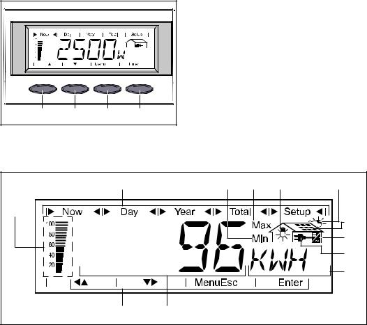
Functions of the keys
(A) |
(B) |
(C) |
(D) |
Key (A) and (B): - for scrolling
key (C):
-for switching to the menu level („Menu“) or exit from the setup menu („Esc“) key „Enter“ (D):
-for confirming a choice
Symbols |
(2) |
(12) |
(11) |
(10) |
(9) |
|
|||||
|
(5) |
|
|
|
(7) |
|
|
|
|
|
|
|
|
|
|
|
(8) |
|
|
|
|
|
(6) |
|
|
|
|
|
(4) |
|
(1) |
(3) |
|
|
|
(1)symbols for keys (A) through (D)
(2)symbols for the display modes „Now“ through „Setup“
18

Symbols |
(3) area for data display ... for displaying the data value measured |
(continued)
(4)area for unit display ... for displaying the measuring unit applicable
(5)segment bar ... indicates at any time the power output fed into the mains at a given time - independent from the display mode chosen.
The screen displays % of the maximum possible power supply out put of your solar inverter
(6)
 ... appears with data readings which are directly related to the public mains network
(7)
 ... appears with data readings which are directly related to the solar modules
(8) ... appears with data readings which are related directly to the
FRONIUS IG unit
(9) ... appears with data readings which are related to environment conditions, like insolation and temperature (optional)
(10)
 ...appears with data readings which are transmitted by the consumption sensor (optional)
(11)Max ... the data reading indicates the maximum within the period of observation (depending on the display mode chosen)
(12)Min ... the data reading indicates the minimum within the period of observation (depending on the mode of display chosen)
Important! The Min. and Max. values do not correspond to the absolute extreme values, as the measuring data value capture takes place at two second intervals
Navigating in the Display
Display illumi- Press any key to activate the display lighting. If no key is pressed during nation 30 seconds, the display lighting stops. At the same time the setup menu
offers a choice between permanently lit or permanently dark display.
EN
19

Menu level |
From the menu level you enter the |
|
|
display mode or the setup menu. |
|
|
Move into the menu surface by |
|
|
pressing key (C) |
|
|
(C) |
|
|
(C) |
the screen displays „Menu“ |
|
- |
|
|
- |
the display is operating in the |
|
|
menu level |
Select display |
(1) |
(2) |
(3) |
(4) |
- |
move into the menu level |
mode |
|
|
|
|
- |
select the desired display mode |
|
|
|
|
|
|
(1) to (4) by pressing keys (A) or |
|
|
|
|
|
|
(B) |
|
|
|
|
|
- |
enter the display mode selected: |
|
|
|
|
|
|
press key „Enter“ (D) |
(A) |
|
|
|
|
|
Note! for the menu item |
|
(A) |
(B) |
|
|
(D) |
„Year“ a real time clock is |
(B) |
|
|
required. The menu item |
|||
|
|
|
|
|
„Year“ is only supported |
|
|
|
|
|
|
|
when the option data recor- |
|
|
|
|
|
|
der is connected. This |
|
|
|
|
|
|
system upgrade is equipped |
(D) |
|
|
|
|
|
with a real time clock. |
|
|
|
|
|
|
20
 Loading...