

Page 1

/ Perfect Charging / Perfect Welding / Solar Energy
HyLOG Fleet
24015F
Operating Instructions
EN
Energy cell
42,0426,0271,EN 003-22112018
Page 2

2
Page 3

Dear reader,
Introduction Thank you for the trust you have placed in our company and congratulations on buying this
high-quality Fronius product. These instructions will help you familiarise yourself with the
product. Reading the instructions carefully will enable you to learn about the many different
features it has to offer. This will allow you to make full use of its advantages.
Please also note the safety rules to ensure greater safety when using the product. Careful
handling of the product will repay you with years of safe and reliable operation. These are
essential prerequisites for excellent results.
EN
3
Page 4

4
Page 5

Contents
Safety rules ................................................................................................................................................ 7
Explanation of safety symbols .............................................................................................................. 7
General ................................................................................................................................................. 7
Proper use ............................................................................................................................................ 8
Safety measures in operation ............................................................................................................... 9
Environmental conditions...................................................................................................................... 9
Safe use................................................................................................................................................ 9
Protecting yourself and others .............................................................................................................. 10
Danger from gases, hazardous materials and suffocation.................................................................... 10
Safety measures in normal operation ................................................................................................... 10
Specific hazards.................................................................................................................................... 11
General information regarding the handling of batteries....................................................................... 11
Danger from batteries ........................................................................................................................... 11
Danger from pressure vessels .............................................................................................................. 11
Warranty and liability............................................................................................................................. 12
Safety inspection................................................................................................................................... 12
Safety symbols...................................................................................................................................... 12
Disposal ................................................................................................................................................ 12
Copyright............................................................................................................................................... 13
General ...................................................................................................................................................... 14
Functionality and device concept.......................................................................................................... 14
Advantages ........................................................................................................................................... 14
Properties.............................................................................................................................................. 15
System configuration ............................................................................................................................ 15
Warning notices on the device.............................................................................................................. 16
Control elements and connections............................................................................................................. 18
Safety.................................................................................................................................................... 18
Controls and connections ..................................................................................................................... 18
Control panel......................................................................................................................................... 20
Before commissioning................................................................................................................................ 23
Safety.................................................................................................................................................... 23
Proper use/intended purpose................................................................................................................ 23
Before using for the first time ................................................................................................................ 24
Connections .......................................................................................................................................... 24
Start-up ...................................................................................................................................................... 26
Safety.................................................................................................................................................... 26
Advance information ............................................................................................................................. 26
Connecting the power interface to the vehicle ...................................................................................... 26
Pin assignment for the vehicle connection............................................................................................ 27
Specification for the vehicle connection................................................................................................ 27
Potential Equalization ........................................................................................................................... 28
Application example for the vehicle connection .................................................................................... 28
Refuelling ................................................................................................................................................... 29
Safety.................................................................................................................................................... 29
General ................................................................................................................................................. 29
General refuelling.................................................................................................................................. 29
Time-optimised refuelling...................................................................................................................... 30
Pressure tolerances .............................................................................................................................. 32
Refuelling process ................................................................................................................................ 32
Operation ................................................................................................................................................... 33
Safety.................................................................................................................................................... 33
Operating conditions ............................................................................................................................. 33
Starting energy delivery ........................................................................................................................ 34
Stopping energy delivery ...................................................................................................................... 34
Troubleshooting ......................................................................................................................................... 35
Safety.................................................................................................................................................... 35
Fault diagnosis...................................................................................................................................... 35
Displayed service codes ....................................................................................................................... 36
Care, maintenance and disposal ............................................................................................................... 38
Safety.................................................................................................................................................... 38
EN
5
Page 6

Minimum maintenance work ................................................................................................................. 39
Once a year / every 1000 operating hours............................................................................................ 39
Annual safety inspection ....................................................................................................................... 39
Maintenance work every 1000 operating hours ....................................................................................40
Service life ............................................................................................................................................ 40
Pressure equipment.............................................................................................................................. 40
Disposal ................................................................................................................................................ 40
Technical data............................................................................................................................................ 41
HyLOG Fleet 24015F............................................................................................................................ 41
6
Page 7
Safety rules
EN
Explanation of
safety symbols
DANGER!
Indicates immediate and real danger.
If it is not avoided, death or serious injury will result.
WARNING!
Indicates a potentially dangerous situation.
Death or serious injury may result if appropriate precautions are not taken.
CAUTION!
Indicates a situation where damage or injury could occur.
If it is not avoided, minor injury and/or damage to property may result.
NOTE!
Indicates a risk of flawed results and possible damage to the equipment.
General
IMPORTANT!
Indicates tips for correct operation and other particularly useful information.
It does not indicate a potentially damaging or dangerous situation.
If you see any of the symbols depicted in the "Safety rules" chapter, special care is required.
The device is manufactured using state-of-the-art technology and according to recognised
safety standards. If used incorrectly or misused, however, it can cause:
- injury or death to the operator or a third party
- damage to the device and other material assets belonging to the operator,
- inefficient operation of the device
According to the extent to which they are operating and using the device, all users (drivers,
service personnel, etc.) must
- be suitably qualified
- be trained
- read and follow these Operating Instructions carefully.
The Operating Instructions must always be at hand wherever the device is being used. In
addition to the Operating Instructions, attention must also be paid to any generally applicable and local regulations regarding accident prevention and environmental protection.
All safety and danger notices on the device:
- must be in a legible state,
- must not be damaged,
- must not be removed,
- must not be covered, pasted or painted over.
7
Page 8

For the location of the safety and danger notices on the device, refer to the section headed
"General remarks" in the Operating Instructions for the device.
The following problems can result in safety issues, and must therefore be resolved before
the device is commissioned:
- dirty or blocked cooling air inlet
- power connector connected incorrectly
This is for your personal safety!
These Operating Instructions are concerned only with the vehicle's energy delivery system
and describe the technical and safety-relevant interfaces on the vehicle relating to energy
delivery.
The overall safety of the system (HyLOG Fleet device, vehicle and its operation in a working area) is the responsibility of the vehicle manufacturer / system integrator. The vehicle
manufacturer / system integrator is the manufacturer of the logistics vehicle that installs the
energy cell in the vehicle and is responsible for the conformity of the system as a whole.
The overall system safety encompasses:
- Weight compensation (driving stability, traction, etc.)
- Information provided to the driver and surrounding area concerning safety-relevant
operating states of the energy cell (warning of hydrogen leak, etc.)
- Analysis of overall system safety and supply of general system user documentation
(energy cell and vehicle) adapted for use of the vehicle with the HyLOG Fleet energy
cell.
Proper use
The device is to be used exclusively for its intended purpose.
Any use above and beyond this purpose is deemed improper. The manufacturer shall not
be held liable for any damage arising from such usage.
Proper use includes:
- ensuring that the device is undamaged and in perfect condition
- carefully reading and obeying all the instructions in these operating instructions, especially the safety rules and all safety and danger notices
- installing the device in accordance with the vehicle manufacturer's operating instructions
- carrying out all the specified inspection and maintenance work *
- observing all instructions of the vehicle manufacturer and the refuelling system manufacturer
- obeying other relevant national safety rules
Inspection and maintenance work form part of the responsibility of the operator. However,
the operator may arrange for the manufacturer of the vehicle or the fuel cell system to perform inspection and maintenance work (e.g. as part of a maintenance agreement).
The device must only be operated in rooms with a volume of more than 10 m³ (353.15 ft³)
and with an air circulation rate of not less than 0.6/h. With a room volume of 10 m³ (353.15
ft³), an air circulation rate of 0.6/h means that 6 m³ (211.89 ft³) of air are renewed per hour.
The device may not be used if any part has been submerged in or flooded with water. Notify
the manufacturer or its representative immediately so that the device can be checked and
any affected parts replaced.
The device must not be used in conditions of frost or (condensing) humidity. Operating the
device in frosty or humid conditions can result in damage. Only use the device in rooms
that are free from frost and condensing air. Detailed information can be found in the "Technical data" chapter.
8
Page 9

Remove the device before washing the vehicle. Never clean the device itself with water,
liquid detergents or steam cleaners.
Safety measures
in operation
Environmental
conditions
Information on cleaning the device can be found in the "Care, maintenance and disposal"
chapter.
When installing devices with openings for cooling air, ensure that the cooling air can enter
and exit unhindered through the air ducts. Only operate the charger in accordance with the
degree of protection shown on the rating plate. Observe the "Operating conditions" chapter
of the device operating instructions.
Operation or storage of the device outside the stipulated environmental conditions will be
deemed to be not in accordance with the intended purpose. The manufacturer shall not be
held liable for any damage arising from such usage.
Additional information on the permitted environmental conditions can be found in the
"Technical data" chapter.
The surrounding air must be clean and free from
- possible ignition sources
- smoke
- naked flames and light
- petrol and other flammable materials in the form of liquids, vapours or electrically conductive dusts, e.g. metallic powder
- corrosive gases or substances
EN
Safe use
Can be used at altitudes of up to 1600 m (5249 ft.)
The operating instructions are primarily intended for system integrators who incorporate
the device as a component into an overall vehicle. The contents are therefore intended for
qualified personnel.
The user must have received verifiable training from a qualified technician authorised by
the manufacturer.
The user must also observe all warning notices of the vehicle supplier and for the hydrogen
refuelling system.
An electric shock can be fatal. Do not perform any actions other than those described in
this documentation. All cables and leads must be secured, undamaged, insulated and adequately dimensioned. Loose connections, scorched, damaged or inadequately dimensioned cables and leads must be immediately repaired by authorised personnel.
Leaks in the hydrogen supply, in combination with an ignition source, pose a risk of fire and
explosion. The hydrogen refuelling system must therefore be set up in compliance with the
applicable standards and guidelines and operated in accordance with the manufacturer's
instructions. The technical data shown on the rating plate applies.
Maintenance and repair work on the device may only be carried out by trained personnel
authorised by the manufacturer.
It is impossible to guarantee that bought-in parts are designed and manufactured to suit
their application, or that they satisfy safety requirements. Use only original replacement
parts (also applies to standard parts).
9
Page 10

Do not carry out any modifications, alterations, etc. to the device without the manufacturer's consent.
Components that are not in perfect condition must be replaced immediately.
Protecting yourself and others
Danger from gases, hazardous
materials and suffocation
Keep unauthorised persons, especially children, away from the device and the vehicle containing the device during operation. If, however, there are people in the vicinity,
- make them aware of all dangers associated with use of the device (possible risk of suffocation due to lack of oxygen in the air, danger from output current, etc.)
- adhere to the permitted operating conditions as specified in the "Operating conditions"
section of the "Operation" chapter
Before leaving the vehicle in which the device is installed, make sure that no injury or damage can occur in your absence.
The fuel is supplied in the form of gaseous hydrogen. Hydrogen is a dangerous substance,
which requires great care when handling. Further information on handling hydrogen can
be found in the safety data sheet of the hydrogen supplier.
Only use the device in well-ventilated areas to prevent the accumulation of explosive gas.
Spaces are not deemed to be at risk of explosion if a concentration of hydrogen of less than
4% by volume can be adequately guaranteed by the use of natural or forced ventilation.
Keep possible ignition sources, fires and naked flames away from the device, also inflammable materials, liquids and gases.
Using the device in spaces with inadequate ventilation can cause suffocation with no visible or otherwise detectable warning. This is because of the oxygen consumption of the device, which can lead to a lack of oxygen in the room if it is inadequately ventilated. The
device must only be operated in rooms with a volume of not less than 10 m³ and with an
air circulation rate of not less than 0.6/h. Example: With a room volume of 10 m³, an air
circulation rate of 0.6/h means that 6 m³ of air are renewed per hour. Other spatial conditions require an exact calculation of the air circulation rate in consultation with the device
manufacturer.
Safety measures
in normal operation
10
Only operate the device if all of its protection devices are fully functional. If the protection
devices are not in full working order, there is a risk of
- injury or death to the operator or a third party
- damage to the device and other material assets belonging to the operator
- inefficient operation of the device
Any safety devices that are not functioning properly must be repaired before switching on
the device.
Never bypass or disable protection devices.
Before switching on the device, ensure that no one is likely to be endangered.
Observe the commissioning and operating requirements as set out in the "Before commissioning" and "Commissioning" chapters.
Page 11

Generally-speaking, the following applies:
- Ensure adequate ventilation of the installation location
- Ensure that the cooling air can flow into and out of the device unhindered
- Refer to the "Care, maintenance and disposal" chapter of the device Operating Instructions
- Regularly check the device and its accessories for obvious damage and proper functioning of safety device(s)
- Never operate the unit if there is any evidence of damage
- Always use the unit in compliance with
- the "Proper use" section of the "Before commissioning" chapter
- the "Operating conditions" section of the "Operation" chapter
EN
Specific hazards
General information regarding the
handling of batteries
Keep hands, hair, clothing and tools away from moving parts, for example fans.
Unauthorised opening or tampering with the device will invalidate the guarantee and poses
the risk of serious damage to people and property.
The unit contains a back-up battery (NiMH-technology) which requires careful handling.
- The back-up battery is maintenance-free
- It must not be tampered with by unauthorised personnel
- If external recharging of the back-up battery is required, this must only be carried out
with a battery charging system approved by the manufacturer (maximum charging current: 35 A, e.g. Acctiva Professional 35A, item number 4,010,335,874. The need to recharge the battery externally represents a fault that can only occur in special situations
(prolonged shutdown, overuse, etc.)
- Do not expose the back-up battery to excessive heat (e.g. do not leave the vehicle
parked in bright sunlight)
- The back-up battery is equipped with a protective circuit. This protects it against:
- Overcharging of the cells (damages the cells)
- Deep discharge of the cells (damages the cells)
- Destruction of cells by short circuit
- Polarity reversal
- Incorrect charging
- Overtemperature
Danger from batteries
Danger from
pressure vessels
The unit contains a back-up battery (NiMH-technology), which requires careful handling.
Batteries contain substances harmful to the eyes and skin. These can only be released in
the event of serious damage (e.g. overheating, accident, etc.).
- Substances escaping from batteries must not come into contact with the eyes, skin or
clothes.
- Do not inhale escaping gases or vapours, and make sure premises are well-ventilated
- Avoid short circuits
- Do not expose the battery to excessive heat or throw it onto an open fire
Further details can be found in the supplementary safety data sheet available from the
manufacturer.
The device is fed with hydrogen from an integrated pressure vessel. Ensure compliance
with the safety rules for pressure vessels.
There is a container of pressurised hydrogen in the device, and it must therefore be treated
with care. Detailed information on proper use can be found in the "Before commissioning"
section.
11
Page 12

Protect the pressure vessel from excessive heat, mechanical impact, naked flames, sparks
and arcs.
Keep pressure vessels away from electrical circuits.
The manufacturer's instructions must be observed as well as applicable national and international regulations for pressure vessels and accessories.
Warranty and liability
Safety inspection
The duration of the guarantee for the device depends on the supply contract. However, the
manufacturer will not accept any liability if the damage was caused by one or more of the
following:
- Use of the charger not in accordance with the intended purpose
- Incorrect operation
- Operating the charger with faulty protection devices
- Non-compliance with the operating instructions
- Unauthorised modifications to the charger
- Catastrophes caused by the activities of third parties and force majeure
A safety inspection must be carried out by a qualified expert
- before using for the first time after installing in the vehicle
- after any changes are made
- after any additional parts are installed, or after any conversions
- after repair, care and maintenance has been carried out
- and at least once every twelve months
The operator is required to carry out a safety inspection of the unit at least once every 12
months and to have the safety elements on the unit function-tested. Applicable national
regulations must be observed.
Maintenance, technical inspections and checks must only be carried out by qualified personnel (service organisations) who have been trained in the safety and maintenance of
these devices. In addition, all repair and maintenance work must be performed exclusively
using original replacement parts. All changes to the device and the use of parts that are
not original replacement parts may only be made with the approval of the manufacturer.
If these conditions are not met, the manufacturer cannot guarantee the safety of the device. Starting up the device without having performed safety-related maintenance work is
done at your own risk.
The manufacturer therefore accepts no liability for damage caused by inadequate maintenance carried out by a third party or by the non-performance of maintenance.
Safety symbols Devices with the CE marking satisfy the essential requirements of the applicable European
directives. Further information can be found in the "Technical data" chapter.
Disposal Do not dispose of this device with normal domestic waste! To comply with the European
Directive on Waste Electrical and Electronic Equipment and its implementation as national
law, electrical equipment that has reached the end of its life must be collected separately
and returned to an approved recycling facility. Any device that you no longer require must
either be returned to your dealer or given to one of the approved collection and recycling
facilities in your area. Ignoring this European Directive may have potentially adverse affects on the environment and your health!
12
Page 13

Copyright Copyright of these operating instructions remains with the manufacturer.
The text and illustrations are all technically correct at the time of printing. We reserve the
right to make changes. The contents of the operating instructions shall not provide the basis for any claims whatsoever on the part of the purchaser. If you have any suggestions for
improvement, or can point out any mistakes that you have found in the instructions, we will
be most grateful for your comments.
EN
13
Page 14

General
Functionality and
device concept
The HyLOG Fleet device allows transport
vehicles for internal logistics to be operated
with hydrogen as the energy source. This
eliminates the long breaks in operation required with normal charging times, as refuelling takes only a few minutes. The result
is higher productivity and lower maintenance costs. Ideally the hydrogen is generated
locally from renewable energy sources. The
only emissions from HyLOG Fleet are small
quantities of pure water.
The key component of HyLOG Fleet is the electrochemical unit in the device - the fuel cell.
This generates electrical energy from hydrogen and from oxygen in the surrounding air.
The fuel cell consists of several individual cells connected in series. A digital control unit
supplies it with hydrogen and air in the correct ratio and maintains the operating temperature.
When used correctly, hydrogen is a safe source of energy. The energy cell has a range of
safety features that comply with applicable standards. The explosion protection requirements are covered by precautionary measures integrated into the device to the extent that
no further explosion protection measures are required at the installation location. Care
must be taken to ensure sufficient circulation of air in the operating environment.
Advantages A great economic advantage of HyLOG Fleet is that long battery charging times are re-
placed by a refuelling process that takes only a few minutes. This results in greater availability and productivity of the in-house transport vehicles, combined with lower
maintenance costs. The hydrogen tank can be refilled virtually any number of times, within
the intended product life cycle of 10 years, whereas batteries always have a limited service
life.
Use of the fuel cell offers a range of other benefits as well:
Water is the only combustion product of the fuel cell, which means that it does not produce
any pollutants. Another advantage of the fuel cell is that it is quiet and requires practically
no maintenance. In contrast to conventional generators, the fuel cell electrochemically converts the chemically-bound energy of the hydrogen directly into electrical power. The hydrogen consumption is therefore very low.
Given the finite nature of energy resources and the need for environment-friendly energy
production, HyLOG Fleet sets new standards for energy efficiency and emission reduction.
The overall logistics system is particularly environment-friendly when renewable energy
sources are used, for example:
- Solar
- Wind
- Water
- Biomass
- Biogas
14
Page 15
The benefits of using HyLOG Fleet as the energy source for internal transport vehicles can
be summed up as follows:
- Long battery charging times of 8 to 10 hours are replaced by a refuelling process that
takes less than 3 minutes
- Lower maintenance costs mean optimum productivity compared with conventional
battery solutions
- Lower operating costs thanks to longer service life of the fuel-cell-based system
- Less space required since there are no battery charging stations
- Absence of poisonous and odorous emissions
- Quiet
- Energy efficiency is roughly 3 times better than that of conventional systems using internal combustion engines
Properties - Fuel cell-based generator
PEM type (polymer electrolyte membrane)
- Simple to operate
- Can easily be integrated into existing vehicle designs
- High standard of safety due to safety functions integrated into the device and explosion protection
- High degree of efficiency
- Quiet, low-maintenance operation
- Interface for data communication
EN
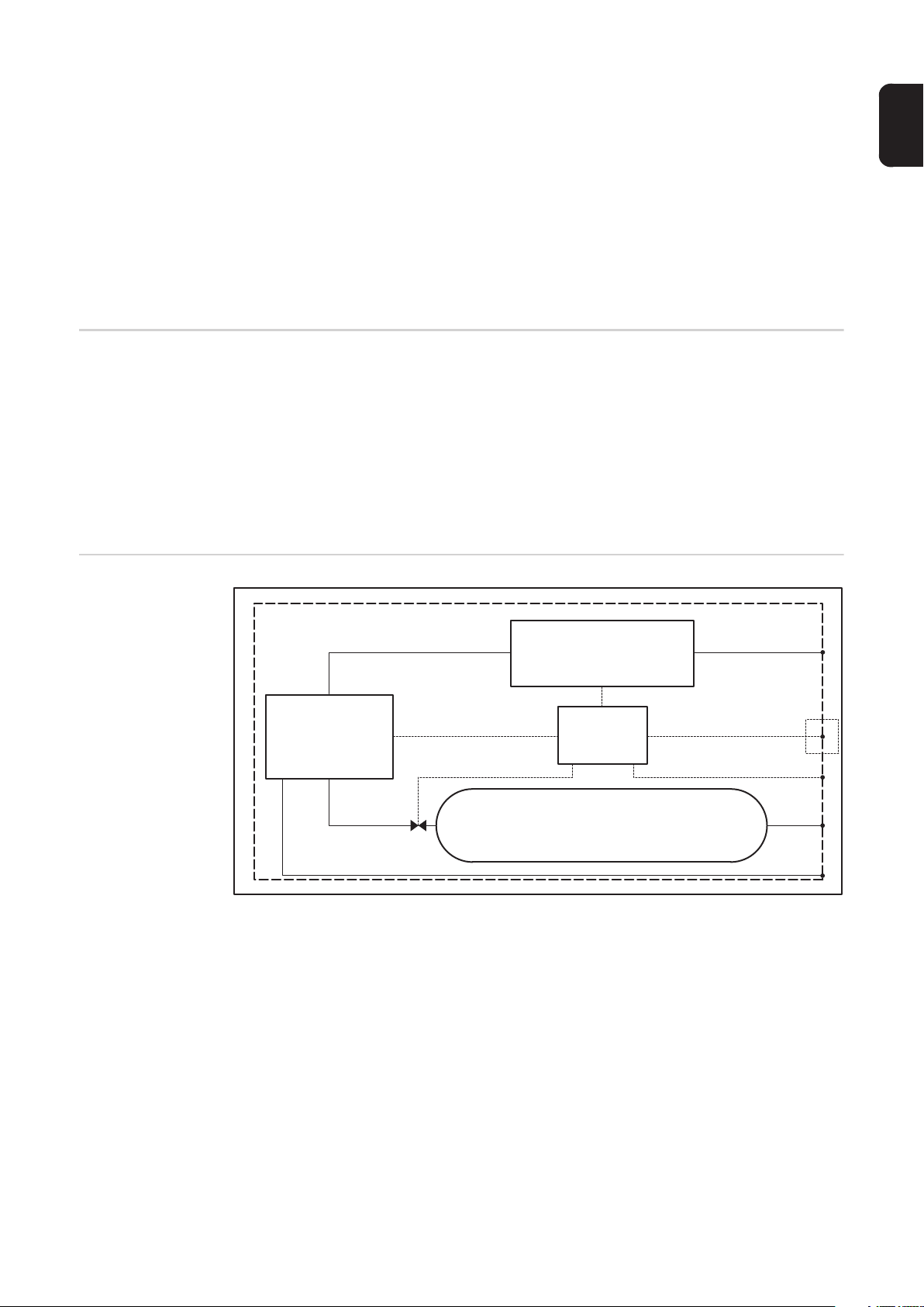
System configuration
NiMH-Battery
Fuel Cell Control Unit
Tank
Power
Control panel
Signal
Refilling
Condensate
15
Page 16
System components
Position Explanation Detailed explanation, specification
Fuel cell Fuel cell Generates electricity via an electrochemical process
from hydrogen and oxygen in the surrounding air ("cold
combustion"). Therefore the fuel cell is extremely efficient.
Battery Battery with nick-
el-metal hydride
technology
Since the fuel cell always works at close to optimum efficiency, it is used primarily to charge the batteries in order to store the energy. If power consumption increases
due to heavy acceleration of the vehicle, this is largely
met by the battery.
On the other hand, when the vehicle is braked, surplus
braking energy is stored in the battery again. The vehicle's drive unit is therefore a highly efficient hybrid system. Once the battery is fully charged, the fuel cell stops.
When the state of charge drops below a certain level, the
fuel cell starts recharging again.
The battery also supplies the energy needed to start the
fuel cell.
Tank A steel vessel for
hydrogen gas
with a capacity of
27 litres (7.13 gallons)
Control
Unit
Control and regulation unit
Contains the energy for operating the vehicle in the form
of hydrogen gas. During the refuelling process, the hydrogen is compressed to a pressure of 350 bar (5074.55
psi.), resulting in high storage density and long operating
intervals between refuelling stops.
Controls the battery charging process and the related
activity of the fuel cell. The optimum state of charge of
the battery is always adapted to the current vehicle operation.
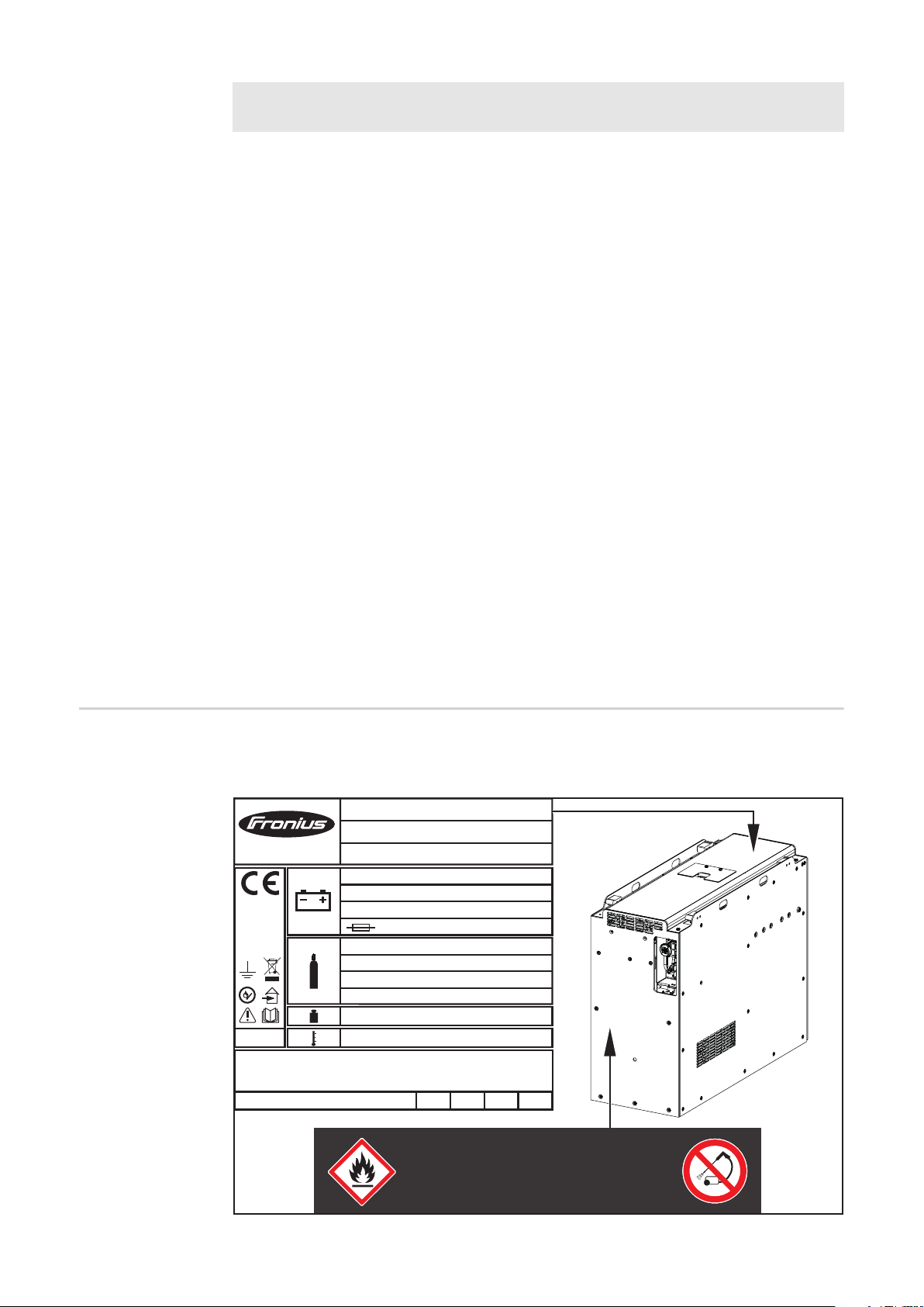
Warning notices
on the device
The device is fitted with a rating plate and safety symbols. The rating plate and safety symbols must not be removed or painted over.
Fronius HyLog Fleet 24015F
Type
Art.No.
www.fronius.com
0036
IP20
WARNING:
OPERATE IN VENTILATED AREAS ONLY - min. Room size 10m³
FOR INDOOR USE ONLY. Do not operate outdoors!
Pressure Vessel production year
Ser.No.
UDC
nom.
I
BATT max.
P
EL. nom.
Fuel type
Pressure nom./max.
Capacity
Receptacle
Weight
Ambient temperature
2015
4,005,101
00000000000
26 V
500 A
1800 W
250 A
Hydrogen SAE J2719
350/438 bar
27 l
SAE J2600 H35
240 kg
+2°C...+40°C (60°C)
2017
2016
2018
CONTAINS HYDROGEN GAS,
HIGHLY FLAMMABLE
DO NOT JET WASH!
16
Page 17
Inadequate ventilation increases the risk of fire, explosion and suffocation. Always operate the device
- with protective grilles fitted on the housing openings for the cooling air supply and outlet
- with sufficient ventilation
- in rooms with a volume of more than 10 m³ (353.15 ft³), with an air circulation rate* of at least 0.6/h
- whilst avoiding oxygen depletion of the surrounding air by ensuring adequate room ventilation
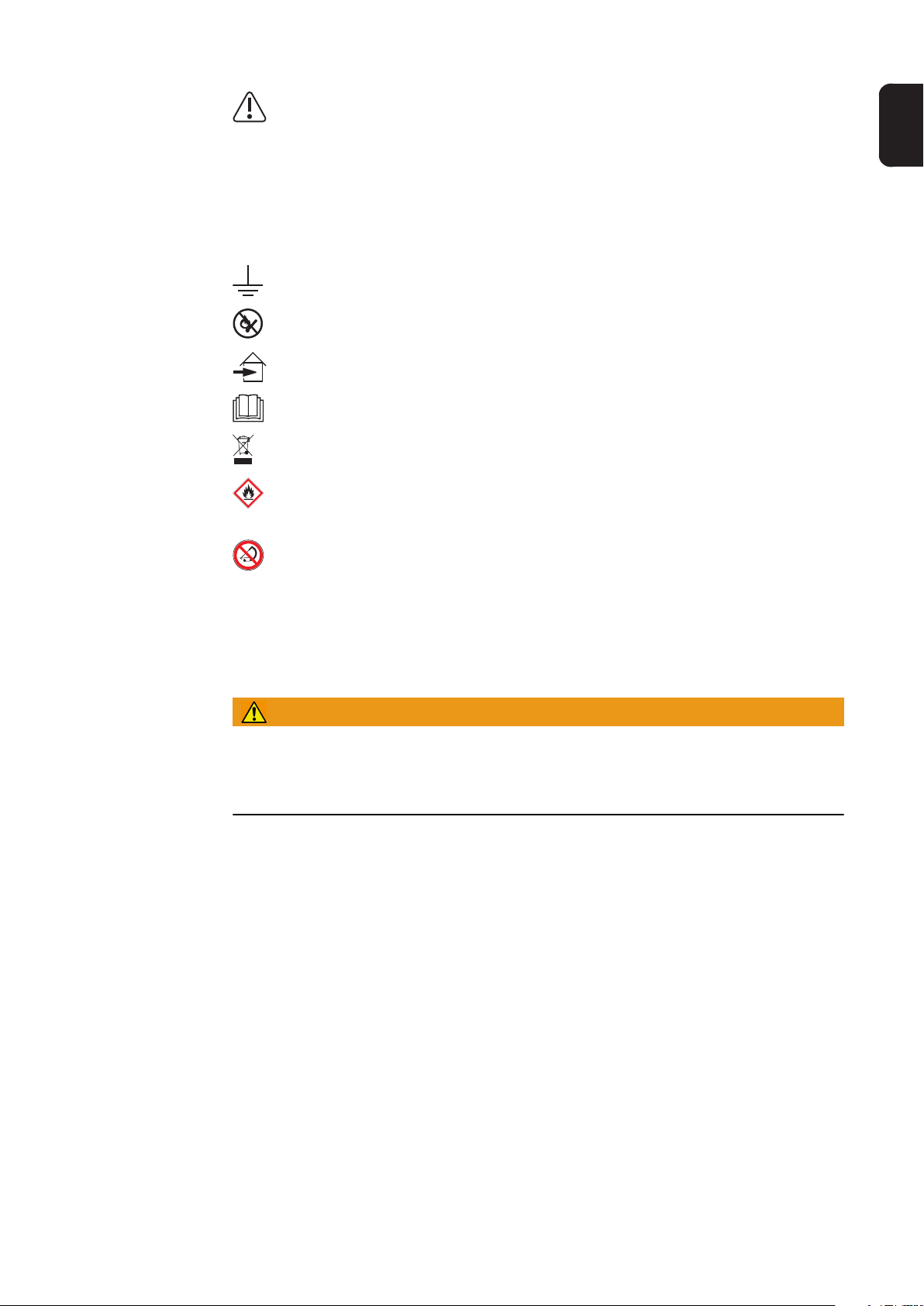
Earthing symbol: A permanent potential equalization must be established between the HyLOG Fleet unit and the vehicle chassis.
Possible sources of ignition, such as fire, sparks and naked lights, must be kept
away from the HyLOG Fleet device.
Degree of protection IP20: For indoor use only. Do not expose to rain.
Do not use the functions until you have read all the Operating Instructions.
Do not dispose of used devices with domestic waste. Dispose of them according
to the safety rules.
Fire hazard! Ensure that the pressurised hydrogen container built into the device
is never exposed to high temperatures, mechanical impact, naked flames or
arcs.
There is a container of pressurised gas in the device, and it must therefore be
treated with care. Never use anything other than a damp cloth to clean the device. Ensure that the device is never exposed to damp conditions.
Pressure Vessel Production Year
EN
* Example: With a room volume of 10 m³ (353.15 ft³), an air circulation rate of 0.6/h
means that 6 m³ (211.89 ft³) of air are renewed per hour.
WARNING!
Danger of serious injury and damage.
The battery must never be short-circuited, penetrated, thrown into a fire, crushed, immersed in water, forcibly discharged or exposed to temperatures outside the permissible
range for the device. The battery must never be used if it is in a defective condition.
In the event that electrolyte and gases escape from the battery as a result of improper treatment, you should proceed as follows:
- If anyone breathes in the escaping gases they may experience breathing difficulties:
Immediately provide air from a fan or take the person outside for fresh air, and in more
serious cases summon medical assistance immediately
- If electrolyte comes into contact with skin, irritations may develop:
Wash the affected area of skin thoroughly with soap and water
- If electrolyte comes into contact with eyes, irritations of the eye may develop:
Immediately rinse the eyes thoroughly with water for 15 minutes and then call a doctor
17
Page 18
Control elements and connections
Safety
NOTE!
After firmware updates, you may notice that your device has certain functions that
are not described in these operating instructions.
Certain illustrations may also differ slightly from the actual controls on your device, but
these controls function in exactly the same way. If you have any further questions, please
contact the manufacturer.
WARNING!
Operating the equipment incorrectly can cause serious damage and injury.
Do not use the functions described here until you have thoroughly read and understood the
following documents:
► these operating instructions
► all the operating instructions for the system peripherals (gas supply, battery, etc.), es-
pecially the safety rules
WARNING!
Work carried out incorrectly and electric shocks can have fatal results.
► All covers of the device and the housing in general should only be opened or removed
by trained technicians
► Unauthorised opening or tampering with the device will invalidate the warranty and cre-
ate the risk of serious injury or damage.
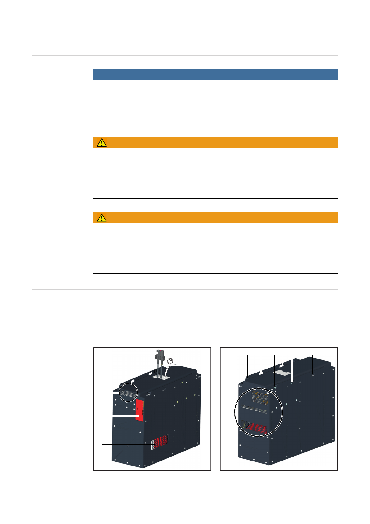
Controls and connections
The device is intended to be installed in vehicles with side-on battery replacement. The device is symmetrically designed in terms of the provided mechanical fixing elements and can
therefore be mounted on the vehicle turned through 180°. This allows you to choose
whether to have the filler connection on the left or right hand side of the vehicle. This issue
should be addressed by the vehicle manufacturer when installing the device in the vehicle.
(8)
(4)
(3)
(2)
(1)
(5)
(6)
(7) (7)(8) (8) (8)
18
Page 19

No. Function
(1) Process air intake
Housing openings for admission of combustion air of the fuel cell process. The volumetric flow is 100 m³/h (3531.5 ft³/h)
WARNING!
If operation of the device is impaired by blocked process air intake openings, there
is a risk of explosion.
Keep all air openings completely clear.
(2) Tank cover, includes:
Tank connection 350 bar (5074.55 psi)
Connection for refilling the compressed hydrogen gas 5.0 (3.0 possible on request), via connection in accordance with ISO 17268 / SAE J2600, connection:
DMB HFR 350 bar (5074.55 psi)
Detailed information can be found in the supplementary document "Refuelling regulations".
Connection socket for condensate drainage
For draining the collection container for reaction water that occurs as condensate.
Detailed information can be found in the supplementary document "Refuelling regulations".
NOTE!
EN
If operation of the device is impaired by a blocked condensate drainage connection,
there is a risk of water leakage.
Keep the condensate drainage connection completely clear.
(3) Cooling air outlet and process exhaust air
Cooling air and exhaust air from the fuel cell process containing steam as a combustion product. The volumetric flow is up to 600 m³/h (21,188.8 ft³/h) at a maximum of 65 °C (149 °F).
WARNING!
If operation of the device is impaired by blocked process air exhaust openings, there
is a risk of explosion.
Keep all air openings completely clear.
(4) Power interface
Connection for the electricity produced. Constant power is up to 1.8 kW at 25.6 V
DC, connection socket: REMA 75012-56
and equipotential bonding
Connection to static equipotential bonding
(5) Connection for the control panel
Connection for the external control panel, which can be mounted on the vehicle
(6) Cooling air intake
Housing openings for admission of cooling air. The volumetric flow is up to 500 m³/
h (17,657.3 ft³/h) at an ambient temperature of up to 40 °C (104 °F)
WARNING!
If operation of the device is impaired by blocked cooling air intake openings, there
is a risk of explosion.
Keep all air openings completely clear.
19
Page 20
Control panel
(7) Locking of the device on the vehicle
Pins for securing the device in the vehicle
If the device is not successfully locked in place, the vehicle will operate in creep
mode (slow travel speed).
WARNING!
Devices that fall over can cause serious injury and damage.
Always ensure that the pins are properly locked.
(8) Crane holder
For transporting the device with suitable load-carrying equipment
WARNING!
Falling devices can cause serious injury and damage.
When transporting with a crane, only use chains or ropes of the same length.
Mount chains or ropes at all the fixing points of the crane holder.
Route the chains or ropes so that the angle to the vertical is as small as possible.
(1)
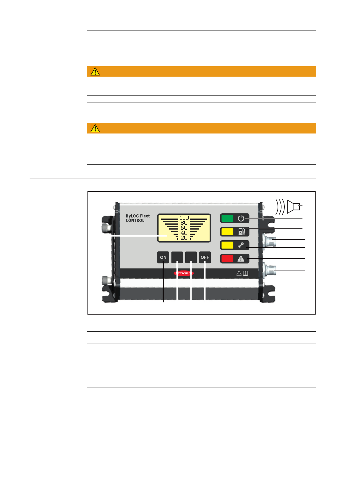
No. Function
(1) Display
The "H2 Tank Level" indicator shows how much hydrogen is left, from 0 to 100% of
the available tank capacity.
Call up of information on operating hours and maintenance
Display of specific text messages on indicators (6), (8), (9) and (10)
(12)
(11)
(10)
(9)
(8)
(7)
(6)
(2) (3) (4) (5)
20
(2) "ON" button
Pressing the "ON" button starts energy delivery. The energy is available immediately. Initially it is provided only by the back-up battery, which at the same time supplies the energy needed to start the fuel cell. The "Power ON" indicator (10) lights
up green.
Page 21

(3) "INFO" button 1
The current function of the button is shown on the display.
The "INFO 1" button provides information on the number of hours for which the de-
vice has already been operated, and how many more operating hours can be expected until the next scheduled maintenance.
The display returns to the "H2 Tank Level" indicator either when the "INFO" 2 button is pressed, or automatically after a certain time.
(4) "INFO" 2 button
The current function of the button is shown on the display.
The "INFO" 2 button acknowledges the relevant indicator on the display and caus-
es a return to the "H2 Tank Level" indicator.
When the "H2 Tank Level" indicator is active, the "INFO" 2 button makes it possible
to call up a list of the most-recently saved service messages. The "INFO" 1 button
is used to scroll through the list.
(5) "OFF" button
The "OFF" button initiates shut down of the fuel cell into the safe state. In the safe
state, all the hydrogen valves that can be activated by the fuel cell are closed.
As soon the fuel cell has been shut down, energy delivery stops.
(6) Connection of control panel
For connecting the control panel to the device
EN
(7) "Fault" indicator, red
In addition to the "Fault" indicator a text message can appear, showing the cause
of the fault. Basically any safety relevant fault leads to a shut down of the device
into the safe state. Try a restart as follows:
Press the "OFF" button - as soon as the device has been shut down, the "Power
ON" indicator goes off
After a waiting time of 10 s press the "ON" button
If the "Fault" indicator still lights up after this new start attempt, contact a Froniustrained service technician, for checking the device.
Another cause of the "Fault" indicator lighting up may be a low state of charge within the integrated back-up battery. If this cause of the fault can be unambiguously
identified based on the text message, recharge the back-up battery using a suitable
charger. More information can be found under "Fault diagnosis" in the "Troubleshooting" section.
(8) "Service" indicator, yellow
The "Service" indicator warns that maintenance is due to be carried out soon.
As soon as the "Service" indicator lights up, contact the manufacturer to arrange
for the necessary maintenance work to be carried out.
NOTE!
Delaying necessary maintenance work can result in performance degradation.
As soon as the "Service" indicator lights up, contact the manufacturer to arrange for the
necessary maintenance work to be carried out.
(9) Vehicle connection
For connecting the control panel to the vehicle. For more information on this, see
the "Commissioning" chapter, and the following sections:
Pin assignment for the vehicle connection
Specification for the vehicle connection
Application example for the vehicle connection
21
Page 22

(10) "Refuel" indicator, yellow
The "Refuel" indicator indicates that refuelling will shortly be required. The display
shows a specific message depending on urgency.
Tank contents less than 20%: indicator lights up yellow
Tank contents less than 10%: indicator flashes yellow
If the tank cover is opened by mistake, the indicator also lights up, with a warning
text. If the message is ignored, it will appear again after one minute.
(11) "Power ON" indicator, green
The "Power ON" indicator signals that the device is ready for use. Thanks to the
integrated back-up battery, energy can be called up at any time - the vehicle can
be started up.
As soon as the fuel cell has powered up, it takes over and meets the energy demand according to the operating strategy by interacting accordingly with the backup battery. The hydrogen in the tank together with the ambient air sucked into the
unit is converted into electricity and water as a combustion product. The back-up
battery primarily caters for low loads and peak demand.
The fuel cell operates in its optimal efficiency range and recharges the back-up battery with surplus power. Once the back-up battery is fully charged, the fuel cell can
be automatically and temporarily shut down.
(12) Acoustic signal - only at devices with Fronius Display
As soon as the device’s internal hydrogen sensor trips, an acoustic warning signal
sounds. At the same time, the "Fault" indicator (6) lights up red. This points to a
hydrogen leak in the system.
In addition to the "Fault" indicator a text message can appear, showing the cause
of the fault. Basically any safety relevant fault leads to a shut down of the device
into the safe state. Try a restart as follows:
Press the "OFF" button - as soon as the device has been shut down, the "Power
ON" indicator goes off
After a waiting time of 10 s press the "ON" button
If the "Fault" indicator still lights up after this new start attempt, contact a Froniustrained service technician, for checking the device.
22
Page 23

Before commissioning
EN
Safety
Proper use/intended purpose
WARNING!
Operating the equipment incorrectly can cause serious injury and damage.
Do not use the functions described here until you have thoroughly read and understood the
following documents:
► these operating instructions
► all operating instructions of the vehicle, the refuelling system and other system compo-
nents, particularly the safety rules
Responsibility for operation of the device rests with the user. Overall vehicle safety (HyLOG Fleet, vehicle and its operation in a working area) is the responsibility of the vehicle
system supplier. The vehicle system supplier must ensure that all safety issues relating to
the integration of the device into the vehicle have been clarified with the device manufacturer.
The device is intended exclusively for the generation of electrical energy from hydrogen
with oxygen from the air and may only be used in a suitable transport vehicle for in-house
logistics, and for production of the electrical energy for driving such vehicles.
In-house transport vehicles are deemed to be suitable if the following conditions are met:
- Analysis of overall system safety and supply of general system user documentation
(energy cell and vehicle) adapted for use of the vehicle with HyLOG Fleet.
- Information provided to the driver and surrounding area concerning safety-relevant
operating states of HyLOG Fleet (warning of hydrogen leak, etc.)
- Weight compensation, if required due to the fact that HyLOG Fleet is lighter than a battery (driving stability, traction, etc.)
Any use above and beyond this purpose is deemed improper. The manufacturer shall not
be held liable for any damage arising from such usage.
Proper use also includes:
- ensuring that the device is undamaged and in perfect condition
- verifiable training of users before using for the first time
- carefully reading and obeying all the instructions in these Operating Instructions, especially the safety rules and all safety and danger notices
- installing the device in accordance with the vehicle manufacturer's Operating Instructions
- carrying out all the specified inspection and maintenance work
- observing all instructions of the vehicle manufacturer and the refuelling system manufacturer
- obeying other relevant national safety rules
WARNING!
Improper operation, maintenance or transportation can result in serious injuries and
damage.
There is a container of pressurised hydrogen in the device, and it must therefore be treated
with care. The regulations on proper use must be observed.
23
Page 24

WARNING!
If operation of the device is impaired due to the device coming into contact with water, there is a risk of suffocation and explosion.
The device may not be used if any part has been submerged in or flooded with water. Notify
the manufacturer or its representative immediately so that the device can be checked and
any affected parts replaced.
Remove the device before washing the vehicle. Never clean the device itself with water,
liquid detergents or steam cleaners.
WARNING!
If operation of the device is impaired due to use in frosty or humid conditions, there
is a risk of suffocation and explosion.
Do not use the device in frosty or humid conditions. Operating the device in frosty or humid
conditions can result in damage. Only use the device in rooms that are free from frost and
condensing air. Detailed information can be found in the "Technical data" chapter.
Information on cleaning the device can be found in the "Care, maintenance and disposal"
chapter.
Before using for
the first time
If operation of the device is impaired by blocked material flows, there is a risk of suffocation and explosion.
Keep all air openings and the condensate drainage connector completely clear.
1
2
3
Connections The device is designed for the output voltages indicated on the rating plate. The hydrogen
refuelling system must be suitable for this connector. The necessary design of the hydrogen refuelling connector is described in the "System Configuration" section of the "General" chapter. If connectors, lines or valves are not attached to your version of the appliance,
fit these components so that they conform to the relevant national standards. The setup
examples are merely recommendations and do not necessarily comply with national standards.
WARNING!
Check that there are no obstructions to the following flows:
- Cooling air supply
- Process air supply
- Process air extraction
- Hydrogen supply
- Condensate drainage
Ensure that the user has received verifiable training from an authorised person
If necessary, charge the battery using a suitable charger.
More information can be found under "Fault diagnosis" in the "Troubleshooting" section.
24
Page 25

During transport the manual tank valve (1)
must be closed. Before using the device,
the manual tank valve (1) has to be opened.
This can be done without openening the
housing from the outside. Using a 3/16 inch
Allen key, open the tank valve by turning it
counterclockwise.
(1)
CAUTION!
Inadequately dimensioned installations and consumers can cause serious damage.
Consumers connected to the device must conform to the output voltages of the device. The
technical data shown on the rating plate applies.
EN
WARNING!
Leaks and escaping hydrogen during the refuelling process in combination with an
ignition source carry the risk of fire, suffocation and explosion.
The refuelling system must be configured according to the applicable standards and the
"Technical data" chapter. Refuelling must only be carried out by properly trained personnel. The technical data shown on the rating plate applies.
25
Page 26

Start-up
Safety
WARNING!
Faulty installation can cause serious damage and injury.
Installation may only be carried out by suitable trained experts in an in-house transport vehicle suitable for that purpose, in accordance with the "Proper use" section of the "Before
commissioning" chapter.
When installing the device, make sure that all material flows are unobstructed, in accordance with the "Before using for the first time" section of the "Before commissioning" chapter. Only operate the charger in accordance with the degree of protection shown on the
rating plate. Observe the "Operating conditions" of the "Operation" chapter.
WARNING!
Work carried out incorrectly can cause overheating and fire.
► Covers and the housing in general should only be opened or removed by the manufac-
turer's trained technicians
► Unauthorised opening or tampering with the device will invalidate the warranty and cre-
ate the risk of serious injury or damage
► Do not carry out any modifications, alterations, etc. to the device without the manufac-
turer's consent.
Advance information
WARNING!
Work carried out incorrectly can cause overheating and fire.
If the device is electrically connected to the integrated back-up battery during installation,
there is a risk of serious injury and damage. Do not carry out any work on the connectors,
unless the device
► is electrically isolated from the integrated back-up battery
► is turned off and in the safe state. For detailed information about the "Safe state", refer
to the "Control panel" section of the "Control elements and connections" chapter
Overall vehicle safety (HyLOG Fleet, vehicle and its operation in a working area) is the responsibility of the vehicle system supplier. The vehicle system supplier must ensure that
all safety issues relating to the integration of the device into the vehicle have been clarified
with the device manufacturer.
Integration of the device into the vehicle is vehicle-specific and requires in-depth knowledge of all safety issues and operation-relevant factors associated with the type of vehicle
in question. The following instructions do not therefore address the integration of the device into the vehicle, but only with the connection and actual start-up of the device.
Connecting the
power interface to
the vehicle
26
WARNING!
Operation with excessive power consumption can result in serious injuries and
damage.
The power consumption of the vehicle must not exceed the power delivery of the device.
Page 27

NOTE!
Pin assignment
for the vehicle
connection
Careless handling of plug connections can cause damage.
When connecting the plug connection for the vehicle's power supply, do not kink, catch or
strain the cables. Renew faulty cables and plug connections.
Connect the power interface (1) on top
1
of the housing with a suitable plug for
(1)
3
2
the vehicle's power supply.
M12 plug connection IEC 61076-2-101
12-pin with coding A
EN
Specification for
the vehicle connection
4
11
10
1
5
9
12
6
7
Relay outputs
K1 max. 30 V, 1 A
K2 max. 30 V, 1 A
Battery_EN
Switching voltage max. 60 V
Switching current max. 1 mA
8
Input
Supply voltage at input max. 60 V
Supply current min. 2 mA
27
Page 28

Potential Equalization
Application example for the vehicle connection
A permanent potential equalization must be established between the HyLOG Fleet system
and the vehicle chassis. The total resistance between the HyLOG Fleet system and the hall
floor should not exceed 25 MOhm. There are 2 possibilities for connecting the device to
the vehicle chassis.
1. Use the grounding contact at the power interface (AUX-contact)
2. Assembly of the control panel (display) on the metal chassis, using a screw connection, which ensures a permanent electrical connection of the display housing to the vehicle chassis.
K1
K2
1
2
3
4
5
6
7
8
9
10
11
12
not connected
CAN-GND
CANH
CANL
Akku_EN+
Akku_ENInput+
Input-
OUT1+
OUT1OUT2+
OUT2-
S1
U1
S2
28
Page 29

Refuelling
EN
Safety
General
WARNING!
Leaks in the hydrogen supply in combination with an ignition source pose a risk of
fire, explosion or suffocation.
The hydrogen refuelling system must therefore be approved by the manufacturer, set up
in compliance with the applicable standards and guidelines and operated in accordance
with the manufacturer's instructions. Refuelling must only be carried out by suitably trained
personnel. The technical data shown on the rating plate applies. The additional instructions
in the following sections of this chapter must be observed.
WARNING!
Overfilling the hydrogen tank poses a risk of explosion and can result in serious injuries and damage.
The refuelling process must be carried out according to the SAE J2601-3 parameters and
the refuelling guideline of the HyLOG Fleet unit. Do not exceed the indicated fuelling rate,
as well as the nominal pressure of 350 bar (5074.55 psi.) at 15 °C (59 °F) and the maximum
filling pressure of 438 bar (6350.43 psi.) at 85 °C (1232.39 °F).
WARNING!
Failure to adhere to the specified fuelling parameters could result in serious injury
or damage.
The specified fuelling parameters must be observed at all times.
- The HyLOG Fleet system may only be refuelled in accordance with the refuelling
guidelines.
- The fuelling system and the fuelling process must be compliant with SAE J26013:JUN2013.
- The nominal pressure of the HyLOG Fleet system is 350 bar (5074.55 psi) at 15 °C
(59 °F). The maximum filling pressure is 438 bar (6350.43 psi) at 85 °C (185 °F).
- The hydrogen temperature stated in the tables below (Hydrogen Temperature, T
refers to the temperature of the hydrogen output by the fuelling system.
- The specified pressure ramp rates must be observed without exception!
- The pressure ramp rates are based on a maximum hydrogen temperature of 85 °C
(185 °F) inside the HyLOG Fleet system.
General refuelling - The HyLOG Fleet system must be refuelled at no more than the specified pressure
ramp rates (Average Pressure Ramp Rate, APRR) in accordance with the hydrogen
temperature of the refuelling system.
- The target pressure (Fuelling Target Pressure) must be observed at all times.
gas
)
Example: A gas temperature ≤ 25 °C (77 °F) and an initial pressure of 2.5 MPa (25 bar)
(362.47 psi) translates into a permissible pressure ramp rate of 14.0 MPa/min (140 bar/
min) (2029.82 psi/min). The maximum filling pressure is 42.5 MPa (425 bar) (6161.95 psi).
29
Page 30

General
24015F Initial Tank Pressure, P0, MPa (psi.)
General refuelling table for HyLOG Fleet 24015F
Average
Pressure
Ramp
Rate,
APRR,
MPa/min
(psi./min)
>65
(149)
65
(149)
60
(140)
55
(131)
50
(122)
45
(113)
40
(104)4(580)
35
(95)
30
(86)
25
(77)14(2030)
20
(68)
10
(50)
0
(32)
Hydrogen Temperature, Tgas, °C (°F)
-10
(14)
-20
(-4)
-30
(-22)
-40
(-40)
>-40
(-40)
no
fuelling
no
fuelling
0,5
(72)1(145)2(290)
no
fuellingnofuellingnofuellingnofuellingnofuellingnofuellingnofuellingnofuellingnofuellingnofuellingnofuelling
no
fuelling
no
fuelling
no
fuellingnofuellingnofuellingnofuellingnofuellingnofuellingnofuellingnofuellingnofuellingnofuellingnofuelling
42,9
(6220)
42
(6089)
Fuelling Target Pressure, Ptarget, MPa (psi.)
2,5
(362)5(725)10(1450)15(2175)20(2900)30(4350)35(5075)
42,9
(6220)
42,5
(6162)
43
(6234)
43
(6234)
>35
(5075)
no
fuelling
no
fuelling
no
fuelling
no
fuelling
no
fuelling
no
fuelling
no
fuelling
no
fuelling
no
fuellingnofuelling
no
fuellingnofuelling
no
fuellingnofuelling
no
fuellingnofuelling
no
fuellingnofuelling
no
fuellingnofuellingnofuelling
no
fuellingnofuellingnofuelling
no
fuellingnofuellingnofuelling
Time-optimised
refuelling
General
Average
24015F
Hydrogen Temperature,
Tgas, °C (°F)
Refuelling time and flow rate for HyLOG Fleet 24015F
40 (104)
25 (77)
Pressure Ramp
Rate, APRR,
MPa/min (psi./min)
4 (580)
14 (2030)
Estimated Refuelling Time, s
Average Flow rate, g/s (lb./s)
Initial Tank Pressure, P0, MPa (psi.)
1 (145)
629 s
1,0 g/s (.00220 lb/s)
176 s
3,6 g/s (.00794 lb/s)
- To optimise the refuelling time, the pressure ramp rate is variable in relation to the initial tank pressure.
- The HyLOG Fleet system must be refuelled at no more than the specified pressure
ramp rates (Average Pressure Ramp Rate, APRR) in accordance with the hydrogen
temperature of the refuelling system and the initial tank pressure.
- The target pressure (Fuelling Target Pressure) as stated in the general refuelling table
must be observed at all times.
Example: A gas temperature ≤ 25 °C (77 °F) and an initial pressure of 2.5 MPa (25 bar)
(362.47 psi) translates into a permissible pressure ramp rate of 20 MPa/min (200 bar/min)
(2899.74 psi/min) for time-optimised refuelling. The maximum filling pressure is 42.5 MPa
(425 bar) (6161.95 psi).
30
Page 31

Optimized Average Pressure Ramp Rate, APRR, MPa/min. (psi./min.)
24015F Initial Tank Pressure, P0, MPa (psi.)
0,5
(72)
>65
(149)
65
(149)
60
(140)
55
(131)
50
(122)
45
(113)
40
(104)
35
(95)
30
(86)
25
(77)
20
(68)
10
(50)
0
(32)
Hydrogen Temperature, Tgas, °C (°F)
-10
(14)
-20
(-4)
-30
(-22)
-40
(-40)
>-40
(-40)
Optimised refuelling for HyLOG Fleet 24015F with variable pressure ramp rate
no
fuellingnofuellingnofuellingnofuellingnofuellingnofuellingnofuellingnofuellingnofuellingnofuellingnofuelling
no
fuellingnofuellingnofuellingnofuellingnofuellingnofuellingnofuellingnofuellingnofuellingnofuellingnofuelling
1
(145)2(290)
4
(580)
14
(2030)
2,5
(362)5(725)10(1450)15(2175)20(2900)30(4350)35(5075)
5
(725)
20
(2900)
16
(2320)
600
(8699)
>35
(5075)
no
fuelling
no
fuelling
no
fuelling
no
fuelling
no
fuelling
no
fuelling
no
fuelling
no
fuelling
no
fuellingnofuelling
no
fuellingnofuelling
no
fuellingnofuelling
no
fuellingnofuelling
no
fuellingnofuelling
no
fuellingnofuellingnofuelling
no
fuellingnofuellingnofuelling
no
fuellingnofuellingnofuelling
EN
24015F
1 (145) 2,5 (362) 15 (2175)
Average
Pressure
Ramp Rate,
APRR,
MPa/min
40 (104)
Hydrogen
Temperature,
Tgas, °C (°F)
25 (77)
Refuelling time and flow rates for HyLOG Fleet 24015F
(psi./min)
Average
Flow Rate,
(g/s)
Estimated
Refuelling
Time (s)
Average
Pressure
Ramp Rate,
APRR,
MPa/min
(psi./min)
Average
Flow Rate,
(g/s)
Estimated
Refuelling
Time (s)
4 (580)
1 (.00220) 1,2 (.00265) 3,4 (.00750)
629 485 105
14 (2030) 20 (2900) 60 (8699)
3,6 (.00794) 5 (.01102) 12,1 (.02668)
176 120 28
Estimated Refuelling Time, s
Average Flow rate, g/s (lb./s)
Initial Tank Pressure, P0, MPa (psi.)
5 (725) 16 (2320)
31
Page 32
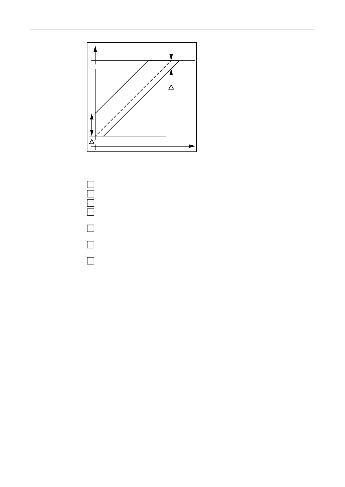
Pressure tolerances
p
p
target
p=25 bar
(362.47 psi)
Upper Pressure Tolerance
Stationary Pressure
Lower Pressure Tolerance
p
p=70 bar (1041.91 psi)
Pressure tolerance range for HyLOG Fleet 24015F
0
During refuelling, the pressure tolerance
range as specified in the following standard
must be observed: SAE J2601:DEC2016
8.3.2.
t
Refuelling process
Press the "OFF" button to shut down the fuel cell and place it in the safe state
1
Open fuel filler flap
2
Connect the condensate drain
3
Connect the filler coupling of the hydrogen refuelling system to the filler connection in
4
accordance with the refuelling system manufacturer's instructions
Carry out the refuelling process in accordance with the instructions of the manufactur-
5
er of the hydrogen refuelling system
Once the hydrogen tank has reached a pressure of 350 bar (5074.55 psi.), the hydro-
6
gen refuelling system automatically stops the refuelling process
Close fuel filler flap
7
32
Page 33
Operation
EN
Safety
WARNING!
Operating the equipment incorrectly can cause serious injury and damage.
Do not use the functions described here until you have thoroughly read and understood the
following documents:
► these operating instructions
► all operating instructions of the vehicle, the refuelling system and other system compo-
nents, particularly the safety rules
WARNING!
Using the device in spaces with inadequate ventilation poses a risk of explosion and
suffocation with no visible or otherwise detectable warning.
This is mainly because of the oxygen consumption of the device. However, it is also possible that a combustible gas mixture will gradually accumulate in the surrounding air.
Therefore, the device must only be operated in rooms with a volume of not less than 10 m³
(353.15 ft ³) and with an air circulation rate of not less than 0.6/h. Example: With a room
volume of 10 m³ (353.15 ft³), an air circulation rate of 0.6/h means that 6 m³ (211.89 ft³) of
air are renewed per hour. Other spatial conditions require an exact calculation of the air
circulation rate in consultation with the device manufacturer.
WARNING!
Operating conditions
Operating and storing the device under environmental conditions different from
those specified here can cause serious injury and damage.
The surrounding air must be clean and free from
► smoke
► open flames and fire
► petrol and other inflammable materials, such as liquids, vapours and dust
► corrosive gases or substances
Can be used at altitudes of up to 1600 m (5249 ft)
Detailed information on the permitted environmental conditions can be found in the "Technical data" chapter.
This device is designed to be operated within a temperature range of between +2 °C
(+36 °F) and +60 °C (+140 °F).
If the device is started at an ambient temperature of between +2 °C (+36 °F) and +20 °C
(+68 °F), the nominal output will not be available until the required process temperature is
reached.
At an ambient temperature range between +40 °C (+104 °F) and +60 °C (+140 °F), or with
inadequate heat dissipation, derating occurs in order to prevent an overload. Premature
degradation of the device can also occur following operation at very high temperatures.
A maximum relative humidity of 85% (non-condensing) is permissible.
33
Page 34
Starting energy
delivery
WARNING!
Operating the device outside the permitted temperature range can result in serious
injuries and damage.
The permitted ambient temperature range is from +2 °C to +60 °C (+36 °F to +140 °F).
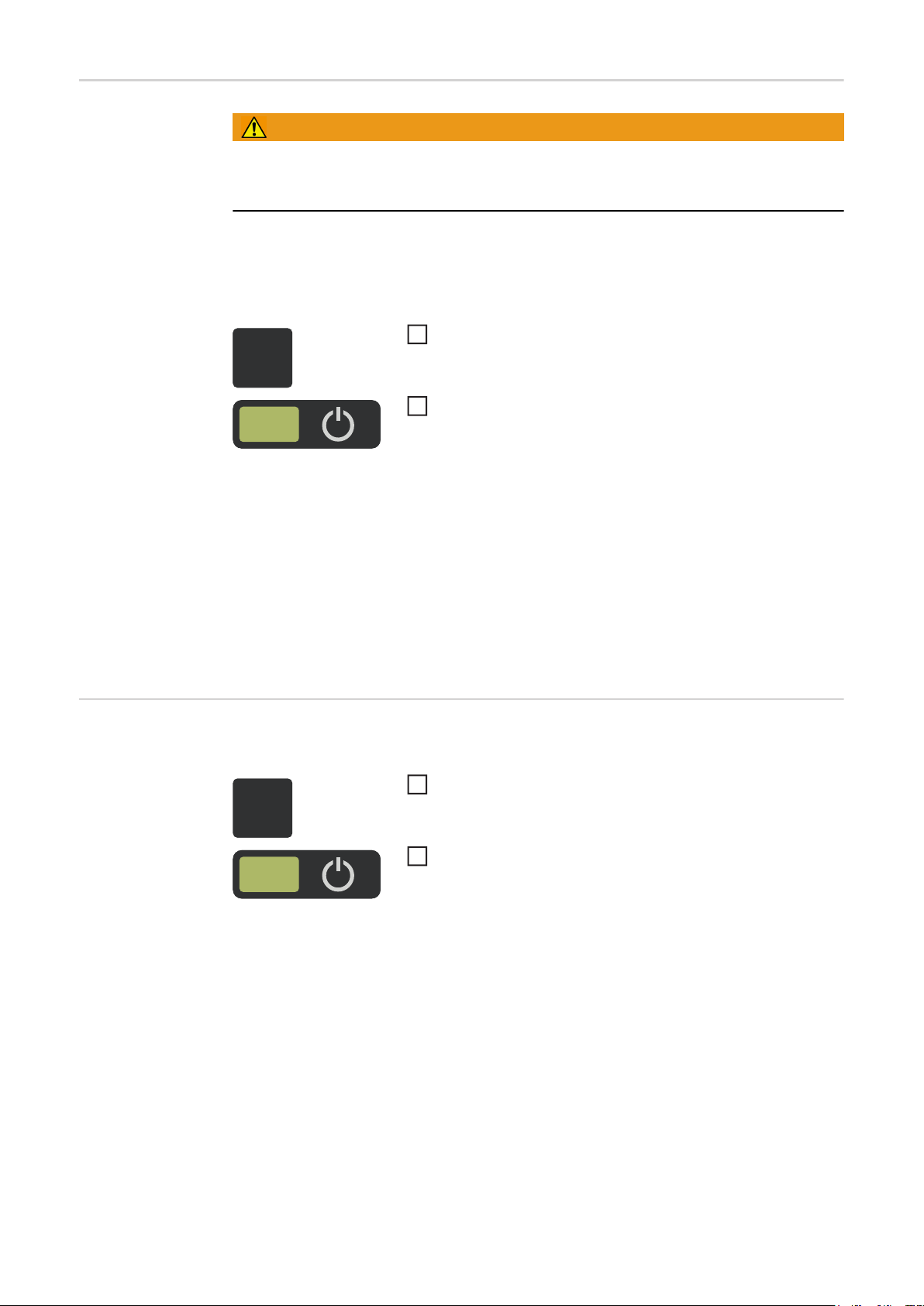
Energy is available as soon as you switch on the device. Initially it is provided only by the
back-up battery, which at the same time supplies the energy needed to start the fuel cell.
Start energy delivery as follows:
Press the "ON" button
1
OFF
ON
The "Power ON" indicator lights up - the energy for operat-
2
ing the vehicle is available immediately.
The fuel cell meets the energy demand according to the operating strategy by interacting
accordingly with the back-up battery. The hydrogen in the tank together with the ambient
air sucked into the unit is converted into electricity and water as a combustion product. The
back-up battery primarily caters for low loads and peak demand.
Stopping energy
delivery
The fuel cell operates in its optimal efficiency range and recharges the back-up battery.
Once the back-up battery is fully charged, the fuel cell can be automatically and temporarily
shut down.
The operating strategy for interaction of the back-up battery and fuel cell can be adapted
to the operating cycle. Contact the manufacturer for further details.
To turn off the fuel cell and stop energy delivery:
Press the "OFF" button - the fuel cell is shut down.
1
OFF
Once the fuel cell has been switched off, it is in the "safe state". This means that all valves
for the hydrogen supply that can be activated by the fuel cell are closed. In the event that
the device is not used for a prolonged period, an automatic safeguard ensures that it does
not consume any energy.
– The display shows that the shut-down process has
been initiated.
The "Power ON" indicator goes off - the energy for operat-
2
ing the vehicle is immediately turned off.
34
Page 35

Troubleshooting
EN
Safety
WARNING!
Work carried out incorrectly can cause overheating and fire.
► All covers of the device and the housing in general should only be opened or removed
by trained technicians
► Unauthorised opening or tampering with the device will invalidate the warranty and cre-
ate the risk of serious injury or damage.
If the covers of the device or the housing are opened by trained personnel, the following
warnings apply:
WARNING!
An electric shock can be fatal.
Do not touch any components in the housing interior before the integrated back-up battery
has been electrically isolated from the device and electrically charged parts (e.g. capacitors) have been discharged. Before opening the device:
► Stop energy delivery by pressing the "OFF" button
► Wait until the "Power ON" indicator has gone off
WARNING!
An electric shock can be fatal.
Do not touch any components in the housing interior before the integrated back-up battery
has been electrically isolated from the device and electrically charged parts (e.g. capacitors) have been discharged. After opening the device
► Electrically isolate the integrated back-up battery from the device
► Put up an easy-to-understand warning sign to stop anybody inadvertently switching it
back on again
► Using a suitable measuring instrument, ensure that electrically charged parts (e.g. ca-
pacitors) have been electrically discharged
Fault diagnosis Contact:
Fronius International GmbH
4600 Wels-Thalheim, Günter-Fronius-Straße 1, Austria
E-mail: energynet.se@fronius.com
http://www.fronius.com
The unit does not function
Cause: The device's integrated battery is flat
Remedy: Recharge the battery using a suitable battery charging system
(maximum current 35 A)
(e.g. Fronius Acctiva Professional 35A, item number 4,010,335,874)
35
Page 36

Displayed service
codes
The basic service messages are shown on the control panel by the specific indicators lighting up, and more specific information is provided in corresponding text messages. Notify
the service technician of the exact combination of indicator and text message.
NOTE!
Ignoring service messages can lead to power reduction.
Arrange for the device to be repaired immediately by a Fronius-trained service technician.
If an error message without a cause that can be rectified immediately appears on the indicators and it cannot be concluded that the cause of the fault is a defect in the safety system, an attempt should first be made to rectify the problem through the following approach:
Stop energy delivery by pressing the "OFF" button
1
Wait until the "Power ON" indicator has gone off
2
Start energy delivery by pressing the "ON" button
3
Wait until the "Power ON" indicator lights up
4
If the fault reoccurs in spite of the restart, it is obviously a defect in the safety system, or
the rectification measures listed here do not result in success:
Note the combination of indicator and text message
1
Note the configuration of the device
2
Contact the device manufacturer with a detailed description of the fault
3
36
Page 37

"Service" indicator lights up
Cause: Important maintenance is due soon.
Remedy: Contact the manufacturer immediately to arrange the necessary maintenance
NOTE!
Delaying necessary maintenance work can lead to power reduction.
As soon as the "Service" indicator lights up, contact the manufacturer to arrange for the
necessary maintenance work to be carried out.
An acoustic signal sounds - only at devices with Fronius-Display
Cause: The hydrogen sensor inside the device has tripped. At the same time, the
"Fault" indicator lights up red. This points to a hydrogen leak in the system. In
addition to the "Fault" indicator a text message can appear, showing the
cause of the fault. Basically any safety relevant fault leads to a shut down of
the device into the safe state.
Remedy: Try a restart as follows:
Press the "OFF" button - as soon as the device has been shut down, the
"Power ON" indicator goes off“
After a waiting time of 10 s press the "ON" button
If the "Fault" indicator still lights up after this new start attempt, contact a Fronius-trained service technician, for checking the device. Park the vehicle in a
well-ventilated environment. Contact the manufacturer immediately to arrange the necessary repairs.
EN
"Fault" indicator lights up
Cause: In addition to the "Fault" indicator a text message can appear, showing the
cause of the fault. Basically any safety relevant fault leads to a shut down of
the device into the safe state.
Remedy: Try a restart as follows:
Press the "OFF" button - as soon as the device has been shut down, the
"Power ON" indicator goes off
After a waiting time of 10 s press the "ON" button
If the "Fault" indicator still lights up after this new start attempt, contact a Fronius-trained service technician, for checking the device. The fault must be rectified by a Fronius-trained service technician. Contact the manufacturer
immediately to arrange the necessary repairs. Of course, the same applies if
the corresponding text message unambiguously identifies the HyLOG Fleet
safety system as the cause of the fault.
Cause: Another cause of the "Fault" indicator lighting up may be a low state of charge
within the integrated back-up battery.
Remedy: If this cause of the fault can be unambiguously identified based on the text
message, recharge the back-up battery using a suitable charger.
(Voltage range: 22 - 28.8 V, maximum current 100 A)
(e.g. Fronius Selectiva Plus 2100, item number 4,010,061)
37
Page 38

Care, maintenance and disposal
Safety Under normal operating conditions, the device requires only a minimum of care and main-
tenance. However, it is essential to observe certain points to ensure that the device gives
reliable service for many years.
WARNING!
Work carried out incorrectly and electric shocks can have fatal results.
► All covers of the device and the housing in general should only be opened or removed
by trained technicians
► Unauthorised opening or tampering with the device will invalidate the warranty and cre-
ate the risk of serious injury or damage.
If the covers of the device or the housing are opened by trained personnel, the following
warnings apply:
WARNING!
An electric shock can be fatal.
Do not touch any components in the housing interior before the integrated battery has been
electrically isolated from the device and electrically charged parts (e.g. capacitors) have
been discharged. Before opening the device:
► Stop energy delivery by pressing the "OFF" button
► Wait until the "Power ON" indicator has gone off
WARNING!
An electric shock can be fatal.
Do not touch any components in the housing interior before the integrated battery has been
electrically isolated from the device and electrically charged parts (e.g. capacitors) have
been discharged. After opening the device
► Electrically isolate the integrated back-up battery from the device
► Put up an easy-to-understand warning sign to stop anybody inadvertently switching it
back on again
► Using a suitable measuring instrument, ensure that electrically charged parts (e.g. ca-
pacitors) have been electrically discharged
WARNING!
Work that is carried out incorrectly can cause serious injury or damage.
Maintenance, technical inspections and checks must only be carried out by qualified personnel. All repairs and maintenance work must be performed exclusively using original replacement parts.
Any changes to the device or the use of parts that are not original spare parts requires the
approval of the manufacturer.
If these conditions are not met, the manufacturer cannot guarantee the safety of the device.
38
Page 39
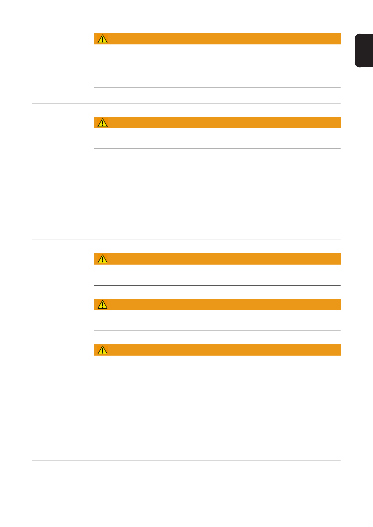
WARNING!
Minimum maintenance work
Starting up the device without having performed safety-related maintenance work
can cause serious injury or damage and is done at your own risk.
The manufacturer accepts no liability for damage caused by inadequate maintenance or
the non-performance of maintenance, as well as in case of continued operation with exceeding the service life of critical components.
WARNING!
A poorly-maintained unit can result in serious injury or damage.
For the unit to operate safely, the specified maintenance tasks MUST be carried out.
The following points must always be observed to ensure safe, problem-free operation of
the device:
- Never use anything other than a dry cloth to clean the device. Ensure that the device
is never exposed to damp conditions
- Always keep the media supply clear
- Check cables and connectors for signs of damage
- Only clean the device with clean and oil-free compressed air
- Observe any additional servicing and maintenance instructions provided by the manufacturer
EN
Once a year /
every 1000 operating hours
WARNING!
A defective gas supply system can cause serious injury and damage.
Inspect the gas supply system in accordance with the applicable national regulations.
WARNING!
A poorly-maintained unit can result in serious injury or damage.
For the unit to operate safely, the specified maintenance tasks MUST be carried out.
WARNING!
Work that is carried out incorrectly can cause serious injury or damage.
Maintenance, technical inspections and checks must only be carried out by qualified personnel. All repairs and maintenance work must be performed exclusively using original replacement parts.
Any changes to the device or the use of parts that are not original parts requires the approval of the manufacturer.
If these conditions are not met, the manufacturer cannot guarantee the safety of the device.
Annual safety inspection
A safety inspection is required at certain intervals, as is the maintenance specified below.
A safety inspection is required once a year. The safety inspection must be carried out by
a Fronius-trained service technician and includes checking all the safety features of the device.
39
Page 40

Maintenance
work every 1000
operating hours
Maintenance must be performed every 1000 operating hours, or earlier if operating conditions dictate (e.g. dusty environment). The maintenance operations are carried out by authorised service technicians and are designed to preserve
- the satisfactory condition of the device
- its performance
- the warranty requirements
Service life
WARNING!
Exceeding the service life of high pressure vessel and tank valve can cause serious
injury and damage.
The high pressure vessel has a service life of 10 years or 11250 full cycles. A warning massage appears on the control panel of the device before reaching the end of the service life.
Exceeding the service life can effect the safety of the vessel and may cause serious damage.
The tank valve has a service life of 50000 switching cycles. A warning message appears
on the control panel of the unit before reaching the end of the service life. Exceeding the
service life can effect the safety of the tank valve and may lead to faulty closing behaviour
and leakage of the valve.
WARNING!
Danger of serious injury and damage if the required maintenance measures and
safety tests are not carried out properly.
The operator is responsible for the safe operation of the device with all maintenance measures and safety checks. If the service life of the components is exceeded, the device must
be taken out of service. In the event of non-compliance with these conditions, the manufacturer does not ensure any safety of the device.
Pressure equipment
Disposal Dispose of in accordance with the applicable national and local regulations.
The device contains a pressure bottle as well as other high pressure components. The applicable national and regional regulations must be observed for their operation. The year
of production of the high-pressure vessel can be taken from the rating plate of the unit. Detailed information on installed components can be found in the attached documents.
40
Page 41

Technical data
EN
HyLOG Fleet
24015F
Input data
Fuel (ISO 14687-2 / SAE J2719) Hydrogen 5.0
(3.0 available on request)
Tank capacity, mass and nominal pressure of the hydrogen contained
Air inlet < 600 m3/h
Fuelling protocol SAE J2601-3
Maximum filling rate see fuelling guideline
Fuel cell data
DC continuous output 1.8 kW
System voltage 25.6 V DC
Fuse protection of the power interface 250 A, 500 A short-term
System efficiency > 47%
27 litres, 0.6 kg, 350 bar
7.13 gal., 1.32 lb., 5074.55 psi.
< 21188.8 cfh
Data relating to the integrated back-up battery
High-performance nickel-metal hydride battery NiMH
Rated operating voltage 25.6 V DC
Nominal capacity approx. 30 Ah
Output data
Concentration of hydrogen in the process exhaust air < 25% of the lower explosive
limit LEL
Air outlet < 600 m³/h at max. 65 °C
< 21188.8 cfh at max. 149 °F
Reaction condensate (purified water, fully desalinated) < 3.2 litres per tank
< .85 gal. per tank
Guidelines
2014/68/EU Pressure equipment guideline
2014/30/EU EMV guideline
41
Page 42

General data
Data interface CAN
Degree of protection IP 20
Marks of conformity CE
Safety standard EN 62282-5-101:2014
Dimensions l x w x h 786 x 310 x 630 mm
30.94 x 12.2 x 24.8 in.
Weight 240 kg
529.11 lb.
Permitted ambient temperature *
(at 85% relative humidity)
Permitted storage temperature
(at 85% relative humidity)
Altitude above sea level max. 1600 m
Must be set up horizontally
* Derating takes place in the range 40 °C to 60 °C (104 °F to 140 °F). This means that
the output power is reduced as far as necessary.
The range 40 °C to 60 °C (104 °F to 140 °F) is only permissible for short-term operation up to 30 minutes.
2 °C to 60 °C
35.6 °F to 140 °F
2 °C to 50 °C
35.6 °F to 122 °F
max. 5249.34 ft.
Connections
Tank connector and connector for equipotential bonding
via electrical connection with vehicle earth potential
Condensate drainage connector Detailed information can be
Power interface REMA 75012-56
Warning and driver information interface max. 30 V DC
CAN service interface CAN 4-pin connection
High pressure equipment
Service pressure 15 °C (59 °F) 350 bar (5074.55 psi.)
Maximum filling pressure 85 °C (185 °F) 438 bar (6350.43 psi.)
Vessel capacity 27 litres (7.13 gal.)
Vessel registration TPED/ADR 2015
Vessel standard ISO 9809-1:2010
Vessel service life 10 years /
Vessel test pressure 525 bar (7611.82 psi.)
OMB HFR
SAE J2600 H35
found in the separate document
"Refuelling regulations".
1 A
11250 complete filling cycles
42
Piping 6 x 1.5 mm (6 x .06 in.)
Pressure holding equipment <DN25 mm (.98 in.)
Page 43

EN
43
Page 44

Fronius International GmbH
Froniusplatz 1
A-4600 Wels
E-Mail: perfect.charging@fronius.com
http://www.fronius.com
Under http://www.fronius.com/addresses you will find all addresses of our sales branches and partner firms!
Fronius Worldwide - www.fronius.com/addresses
 Loading...