

Page 1

Fronius prints on elemental chlorine free paper (ECF) sourced from certified sustainable forests (FSC).
/ Perfect Charging / Perfect Welding / Solar Energy
High Speed Touch Sensing
Installationsanleitung
DEEN
Systemerweiterung
Installations instructions
System extension
42,0410,0985 005-16092019
Page 2

2
Page 3

Einbauanleitung „High Speed Touch Sensing“
DE
Sicherheit
Funktionsbeschreibung
WARNUNG!
Fehlerhaft durchgeführte Arbeiten können schwerwiegende Personen- und Sachschäden verursachen.
Nachfolgend beschriebene Tätigkeiten dürfen nur von geschultem Fachpersonal durchgeführt werden. Nachfolgend beschriebene Tätigkeiten erst durchführen, wenn folgende Dokumente vollständig gelesen und verstanden wurden:
► diese Bedienungsanleitung
► sämtliche Bedienungsanleitungen der Systemkomponenten, insbesondere Sicher-
heitsvorschriften
WARNUNG!
Ein elektrischer Schlag kann tödlich sein.
Vor Beginn der Arbeiten
► Netzschalter der Stromquelle in Stellung - O - schalten
► Stromquelle vom Netz trennen
► ein verständliches Warnschild gegen Wiedereinschalten anbringen
„High Speed Touch“ Sensing dient zum Erkennen der Nahtposition beim automatisierten
Schweißen. Das Ermitteln der Nahtposition läuft wie folgt ab:
Vorgegebene Position für Schweißstart
Werkstückberührung 1
- Der Schweißbrenner fährt an die vorgegebene Position für den Start des
Suchvorgangs
- Die Robotersteuerung setzt den digitalen Ausgang „Aktivieren Touch-Sensor.“
Der Schweißbrenner fährt in eine Richtung
quer zum Schweißnaht-Verlauf, bis
- der Schweißdraht das Werkstück berührt
- die Stromquelle das Signal „Touch
sensing“ generiert
Der Schweißbrenner fährt in die entgegengesetzte Richtung quer zum SchweißnahtVerlauf, bis
- der Schweißdraht das Werkstück berührt
- die Stromquelle das Signal „Touch
sensing“ generiert
Werkstückberührung 2
3
Page 4

Errechnete Position für Schweißstart
- Die Robotersteuerung speichert die
beiden Positionen der Werkstückberührung
- Über einen geeigneten Algorithmus errechnet die Robotersteuerung daraus
die ideale Startposition des Schweißbrenners
Signalübertragung
Das Signal „Touch Sensing“ löst bei Werkstückberührung wie folgt aus:
- Während des gesamten Suchvorganges setzt die Robotersteuerung das digitale Ausgangssignal „Aktivieren Touch-Sensor“
- Dieses Signal aktiviert den digitalen Eingang „Touch sensing“ für die Stromquelle
- Falls vorhanden, zeigt das Display während des gesamten Suchvorgangs die Meldung „TOUCH“
- Die Stromquelle gibt eine strom- und leistungsbegrenzte Signalspannung an den
Schweißdraht aus
Dabei verhindert die Strom- und Leistungsbegrenzung ein Verschweißen des Schweißdrahtes mit dem Werkstück.
- Bei Werkstück-Berührung generiert die Stromquelle das Signal „Touch sensing“.
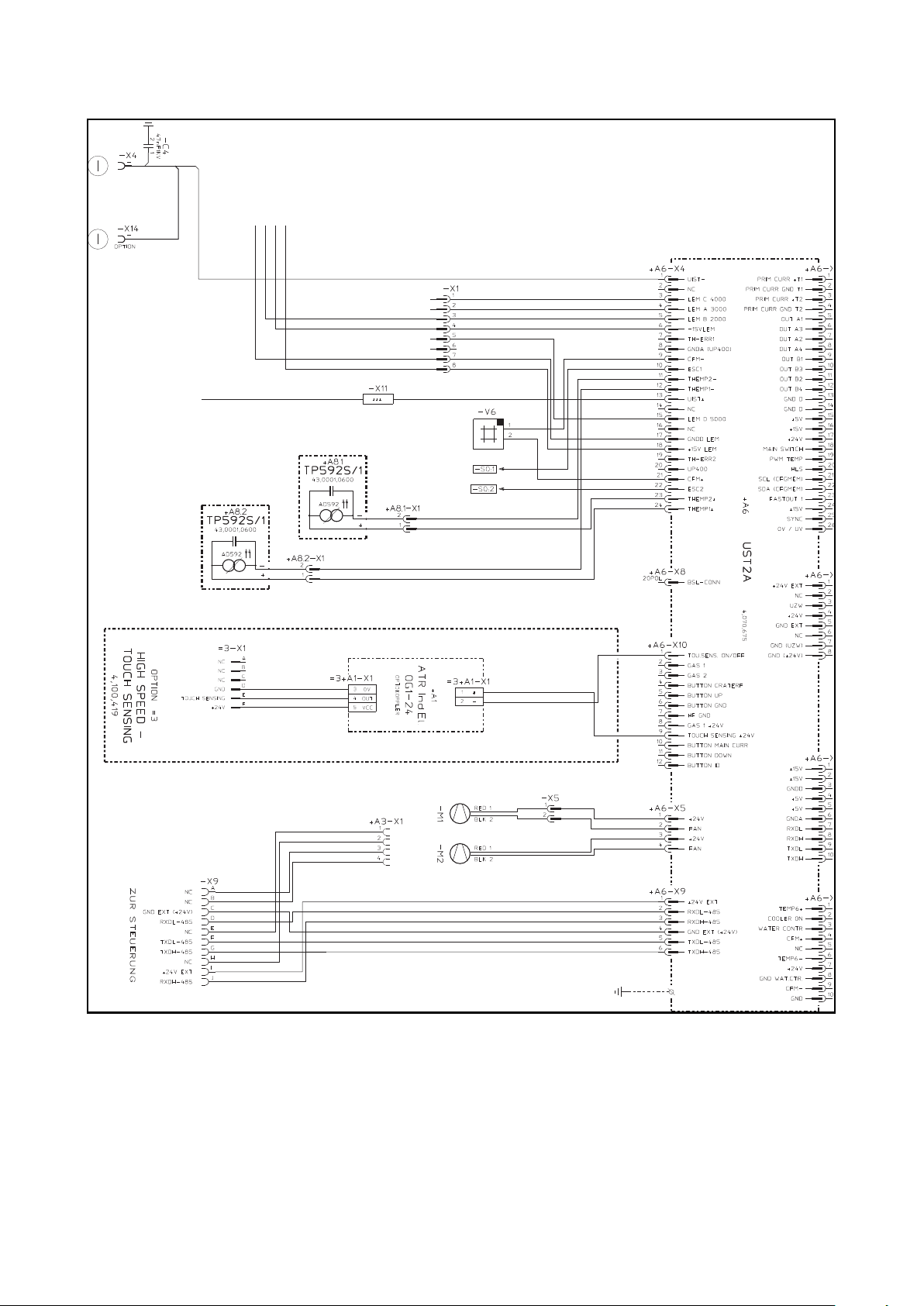
- Das 6-polige Pin-Gehäuse an der Stromquellen-Rückwand hat einen Signalausgang
für „Touch sensing“
- Der eingebaute Optokoppler sorgt für eine galvanische Trennung dieses Signals von
der Netzspannung.
UST2A
4,070,675
+ A6
TOUCH SENSING
GND
+ 24 V
-X1
A
NC
B
NC
C
NC
D
E
F
+ A1-X1
0 V
4
OUT
5
VCC
3
OT1-24
+ A1
+ A1-X1
+
1
-
2
+ A6-X10:9 (+24 V)
+ A6-X10.1 (ON/OFF)
Optokoppler
6-poliges Pin-Gehäuse an der
Stromquellen-Rückwand
Anschlüsse am Optokoppler
LED am Optokoppler
(1)
Optokoppler
Erfolgt eine Werkstückberührung:
- Transistoren im Optokoppler schalten
- Die grüne LED (1) am Optokoppler
12-poliger Molexstecker
am Print UST2A:X6
das Signal an den Ausgang
leuchtet
4
Page 5

Bauteile Das Einbauset „High Speed Touch Sensing“ 4,100,419 besteht aus folgenden Bauteilen:
(1) Optokoppler (Befestigungswinkel
nicht abgebildet)
(2) Kabelbinder
(1)
(2)
(3) Aufkleber zur Kennzeichnung des
Einbausets „High Speed Touch
Sensing“ an der StromquellenRückseite
(6)(8) (7)
(5)
(4)
(4) 12-poliger Molexstecker
(5) 6-poliges Stiftgehäuse
(6) 2 Befestigungsschrauben für Stift-
(3)
gehäuse
(7) Distanzen für Montage Optokoppler
Einbauset „High Speed Touch Sensing“
(8) Buchsengehäuse für 6-poliges
Stiftgehäuse
Optokoppler einbauen
DE
(1)
Optokoppler montieren: bevorzugte Montageposition
(2)
(1)
(2)
Optokoppler montieren: Detailansicht an der Rückwand
(1) Netzschalter der Stromquelle in
Stellung -O- schalten
(2) Stromquelle vom Netz trennen
(3) Rechtes Seitenteil abmontieren
(4) Optokoppler (1) im oberen Bereich
der Rückwand an den geeigneten
Befestigungsbohrungen positionie-
ren
(5) Optokoppler (1) mittels den beiden
mitgelieferten Distanzen (2) mon-
tieren
5
Page 6

6-poliges Stiftgehäuse einbauen
(4)
(6)
(4)
(5)
(6)
Aukleber aufkleben
(6)
(2)
6-poliges Stiftgehäuse montieren
(1) Gehäuseteil (1) vom 6-poligen Buchsengehäuse (2) abschrauben
(2) Gehäuseteil (1) auf die Leitung zur Robotersteuerung (3) schieben
(3) Leitung zur Robotersteuerung (3) am 6-poligen Buchsengehäuse (2) anschließen
(4) Gehäuseteil (1) mit dem 6-poligen Buchsengehäuse (2) verschrauben
(5) Rückwand (4) der Stromquelle: 6-poliges Stiftgehäuse (5) vom Optokoppler an ei-
ner geeigneten Durchführung der Stromquellen-Rückseite positionieren
(6) 6-poliges Stiftgehäuse (5) mittels zweier beiligenden Schrauben (6) montieren
(1)
(3)
(1)
(1) Mitgelieferten Aufkleber (1) neben
dem 6-poligen Stiftgehäuse an der
Stromquellen-Rückwand aufkleben
(5)
(6)
Aufkleber
6
Page 7
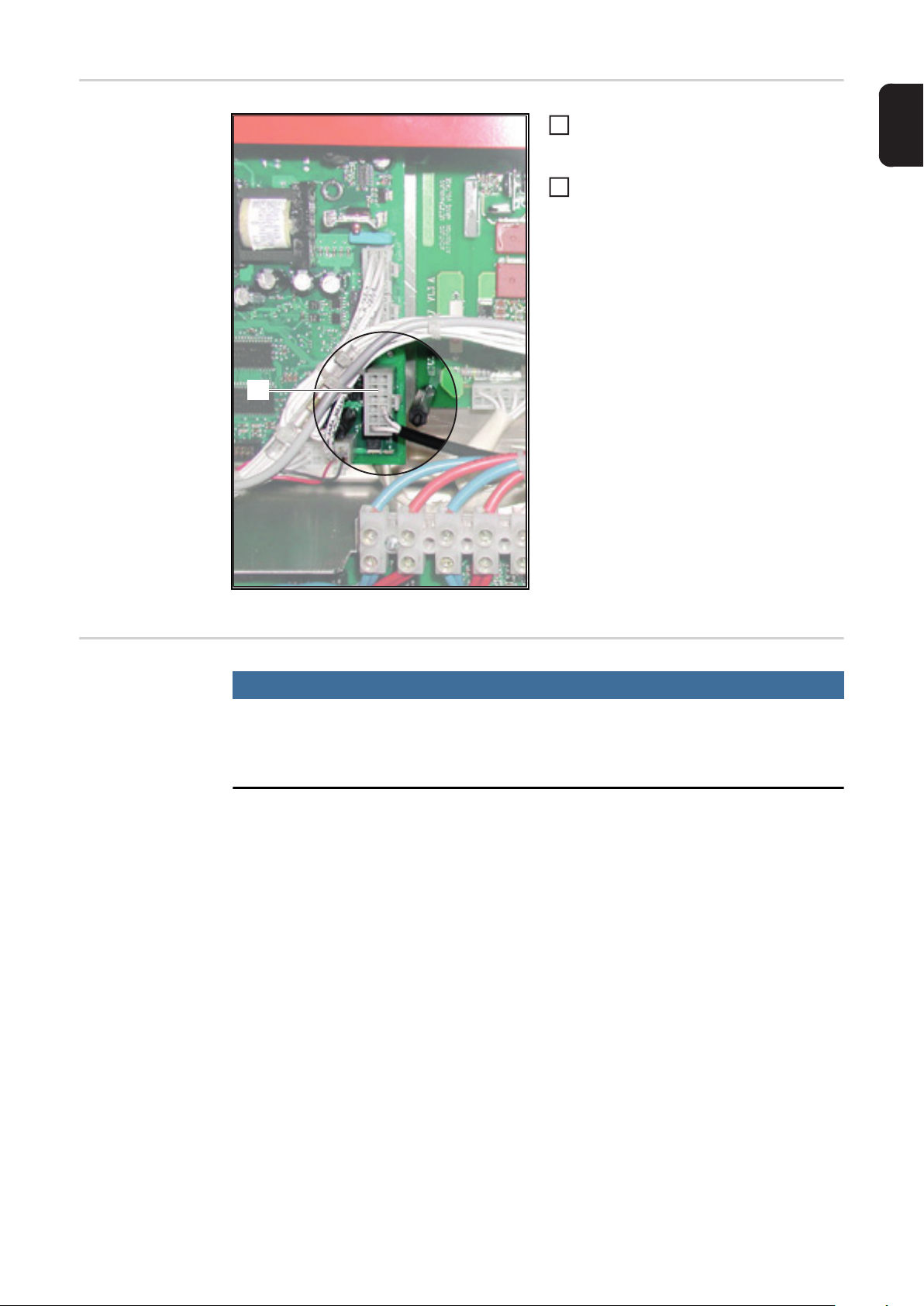
Optokoppler anschließen
(1)
12-poligen Molexstecker (1) vom Opto-
1
koppler am Print UST2A bei X10 anstecken
Kabel mittels beiliegendem Kabelbin-
2
der befestigen
DE
Gehäuse schließen
Optokoppler anschließen
HINWEIS!
Beim Montieren des rechten Seitenteiles darauf achten, dass die Kabel vom Optokoppler zum Molexstecker und zum 6-poligen Stiftgehäuse weder geknickt, eingeklemmt noch auf Zug belastet werden können.
- Rechtes Seitenteil montieren
7
Page 8

8
Page 9

High Speed Touch Sensing Installation Instructions
Safety
Function overview
WARNING!
Work that is carried out incorrectly can cause serious injury or damage.
The activities described below must only be carried out by trained and qualified personnel.
Do not carry out the activities described below until you have fully read and understood the
following documents:
► these operating instructions
► all the operating instructions for the system components, especially the safety rules
WARNING!
An electric shock can be fatal.
Before starting work:
► turn the power source mains switch to the 0 position
► disconnect the power source from the mains
► put up an easy-to-understand warning sign to stop anybody inadvertently switching it
back on again
High Speed Touch Sensing is used to recognise the weld seam position during automated
welding. The weld seam position is detected as follows:
EN
Predetermined position for start of welding
Touching the workpiece 1
- The welding torch moves to the prede-
termined position for the start of the search process
- The robot control produces the „activa-
te touch sensor“ digital output.
The welding torch moves at an angle to the
weld seam until:
- the welding wire touches the work-
piece
- the power source generates the „touch
sensing“ signal
The welding torch moves in the opposite direction at an angle to the weld seam until:
- the welding wire touches the work-
piece
- the power source generates the „touch
sensing“ signal
Touching the workpiece 2
9
Page 10

Calculated position for start of welding
- The robot control saves the two posi-
tions where the workpiece was touched
- The robot control calculates the ideal
start position for the welding torch
using a special algorithm
Signal transmission
The „touch sensing“ signal is emitted when the workpiece is touched as follows:
- Throughout the searching process, the robot control produces the „activate touch sensor“ digital output signal
- This signal activates the „touch sensing“ digital input for the power source
- If present, the display shows the „TOUCH“ message throughout the process
- The power source produces a current and power-limited signal voltage to the welding
wire.
The limited current and power prevent the welding wire from being accidentally welded to
the workpiece.
- The power source generates the „touch sensing“ signal once it touches the workpiece.
- The 6-pin male connector on the rear of the power source has a signal output for
„touch sensing“
- The integrated optical coupler electrically isolates this signal from the mains voltage
UST2A
4,070,675
-X1
A
NC
B
NC
C
NC
D
GND
TOUCH SENSING
+ 24 V
E
F
6-pin male connector on the
rear of the power source
+ A1-X1
0 V
4
OUT
5
VCC
3
Optical coupler
OT1-24
+ A1
+ A1-X1
1
+
-
2
+ A6-X10:9 (+24 V)
+ A6-X10.1 (ON/OFF)
12-pin Molex plug on
UST2A:X6 PC board
+ A6
Optical coupler
Connections on optical coupler
LED on optical coupler
(1)
When the workpiece is touched:
- Transistors within the optical coupler
switch the signal to the output
- The green LED (1) on the optical coupler lights up
10
Page 11

Components The High Speed Touch Sensing 4,100,419 installation set consists of the following compo-
nents:
(1) Optical coupler (fastening bracket
not shown)
(2) Cable tie
(1)
(2)
(3) Label to identify the „High Speed
Touch Sensing“ installation set on
the rear of the power source
(4) 12-pin Molex plug
(6)(8) (7)
(5)
(4)
(5) 6-pin male connector
(6) 2 fastening screws for male
connector
(3)
(7) Spacers for optical coupler assem-
bly
High Speed Touch Sensing Installation Set
(8) Femal connector housing for 6-pin
male
Installing the optical coupler
EN
(1)
Fitting the optical coupler: preferred fitting position
(2)
(1)
(2)
Fitting the optical coupler: detailed view of rear panel
(1) Switch the power source mains
switch to the -O- position
(2) Unplug the power source from the
mains
(3) Remove the right side panel
(4) Position the optical coupler (1) near
the top of the rear panel on the cor-
rect fastening holes
(5) Fit the optical coupler (1) using the
two spacers (2) supplied
11
Page 12

Fitting the 6-pin
male connector
(4)
(6)
(4)
(5)
(6)
Stick label on
(6)
(2)
Fitting the 6-pin male connector
(1) Unscrew housing part (1) from 6-pin female connector (2)
(2) Push housing part (1) onto the cable to the robot control (3)
(3) Connect the cable to the robot control (3) to the 6-pin female connector (2)
(4) Screw together housing part (1) with the 6-pin female connector (2)
(5) Rear panel of the power source (4): position the 6-pin male connector (5) from the
optical coupler on a suitable bushing on the rear panel of the power source
(6) Fit the 6-pin male connector (5) using the two screws (6) supplied
(1)
(3)
(1)
(1) Stick the label supplied (1) onto the
rear panel of the power source next
to the 6-pin male connector
(5)
(6)
12
Label
Page 13

Connecting the
optical coupler
(1)
Connect the 12-pin Molex plug (1) from
1
the optical coupler to X10 on the
UST2A PC board
Secure the cables using the attached
2
cable tie
EN
Closing the housing
Connecting the optical coupler
NOTE!
When fitting the right side panel, ensure that the cable from the optical coupler to
the Molex plug and the 6-pin male connector cannot be kinked, trapped, or strained.
- Fit the right side panel
13
Page 14
High Speed Touch Sensing
14
Page 15

EN
15
Page 16

FRONIUS INTERNATIONAL GMBH
Froniusstraße 1, A-4643 Pettenbach, Austria
E-Mail: sales@fronius.com
www.fronius.com
Under www.fronius.com/contact you will find the addresses
of all Fronius Sales & Service Partners and locations
 Loading...