


Fronius prints on elemental chlorine free paper (ECF) sourced from certified sustainable forests (FSC).
/ Perfect Charging / Perfect Welding / Solar Energy
Drive EasyTwin
Operating Instructions
EN
System extension
42,0426,0194,EN 005-25052020

2

Dear reader,
Introduction Thank you for the trust you have placed in our company and congratulations on buying this
high-quality Fronius product. These instructions will help you familiarise yourself with the
product. Reading the instructions carefully will enable you to learn about the many different
features it has to offer. This will allow you to make full use of its advantages.
Please also note the safety rules to ensure greater safety when using the product. Careful
handling of the product will repay you with years of safe and reliable operation. These are
essential prerequisites for excellent results.
EN
Explanation of
safety notices
DANGER!
Indicates immediate danger.
► If not avoided, death or serious injury will result.
WARNING!
Indicates a potentially hazardous situation.
► If not avoided, death or serious injury may result.
CAUTION!
Indicates a situation where damage or injury could occur.
► If not avoided, minor injury and/or damage to property may result.
NOTE!
Indicates a risk of flawed results and possible damage to the equipment.
3

4

Contents
Installation and commissioning .................................................................................................................. 7
Standard and PowerLiner variants........................................................................................................ 7
Installing the CrashBox Drive EasyTwin on the robot........................................................................... 8
Attaching the torch neck ....................................................................................................................... 9
Securing the hosepack to the spring balancer suspension devices ..................................................... 9
Connecting the hosepack ..................................................................................................................... 10
Installing the wirefeeding hose in the Robacta Drive EasyTwin ........................................................... 10
Threading the welding wire................................................................................................................... 11
Safety rules ................................................................................................................................................ 15
General ................................................................................................................................................. 15
Proper use ............................................................................................................................................ 15
Environmental conditions...................................................................................................................... 15
Obligations of the operator.................................................................................................................... 16
Obligations of personnel ....................................................................................................................... 16
Mains connection.................................................................................................................................. 16
Protecting yourself and others .............................................................................................................. 16
Noise emission values .......................................................................................................................... 17
Danger from toxic gases and vapours .................................................................................................. 17
Danger from flying sparks ..................................................................................................................... 18
Risks from mains current and welding current...................................................................................... 18
Meandering welding currents................................................................................................................ 19
EMC Device Classifications .................................................................................................................. 20
EMC measures ..................................................................................................................................... 20
EMF measures...................................................................................................................................... 20
Specific hazards.................................................................................................................................... 21
Requirement for the shielding gas ........................................................................................................ 22
Danger from shielding gas cylinders..................................................................................................... 22
Safety measures at the installation location and during transport ........................................................ 22
Safety measures in normal operation ................................................................................................... 23
Commissioning, maintenance and repair.............................................................................................. 24
Safety inspection................................................................................................................................... 24
Disposal ................................................................................................................................................ 24
Safety symbols...................................................................................................................................... 24
Data protection...................................................................................................................................... 24
Copyright............................................................................................................................................... 25
General ...................................................................................................................................................... 26
Regarding these operating instructions ................................................................................................ 26
Comparison of Drive EasyTwin with TimeTwin Digital.......................................................................... 26
Drive EasyTwin advantages ................................................................................................................. 26
Drive EasyTwin functional principle ...................................................................................................... 26
Lead power source and trail power source........................................................................................... 27
Drive EasyTwin application areas......................................................................................................... 27
Dimensioning of the robot..................................................................................................................... 27
Welding torch cleaning station.............................................................................................................. 28
System requirements ................................................................................................................................. 29
System requirements and minimum equipment for Drive EasyTwin .................................................... 29
Drive EasyTwin mechanical requirements............................................................................................ 29
Control elements and connections............................................................................................................. 30
Drive EasyTwin drive unit controls........................................................................................................ 30
Welding technology aspects ...................................................................................................................... 31
Shielding gases for Drive EasyTwin ..................................................................................................... 31
Gas flow for Drive EasyTwin................................................................................................................. 31
Earth connection................................................................................................................................... 31
Welding circuit inductivity L, welding circuit resistance r....................................................................... 31
Stick out ................................................................................................................................................ 32
Tilt angle of the welding torch ............................................................................................................... 32
Arc combination options........................................................................................................................ 32
PCS/pulsed ................................................................................................................................................ 33
Symbols ................................................................................................................................................ 33
Material transfer .................................................................................................................................... 33
EN
5

Special features and advantages.......................................................................................................... 33
Potential applications, area of application............................................................................................. 33
Welding parameter standard values .......................................................................................................... 34
Alignment of welding torch relative to the workpiece for fillet welds ..................................................... 34
Alignment of welding torch relative to the workpiece for lap joints........................................................ 34
Area of application for Drive EasyTwin - steel, diameter 1.2 mm - 1.0 mm.......................................... 35
Welding technology options.................................................................................................................. 35
Care, maintenance and disposal ............................................................................................................... 37
General ................................................................................................................................................. 37
Example: consumption of filler metal .................................................................................................... 37
Before shift starts/before starting up..................................................................................................... 37
After 25 hours of arc time...................................................................................................................... 37
After 50 hours of arc time...................................................................................................................... 37
Disposal ................................................................................................................................................ 37
Replacing wearing parts ............................................................................................................................ 38
Preparation replacing the feed rollers and nozzle................................................................................. 38
Replacing the inlet nozzle..................................................................................................................... 40
Replacing the feed rollers ..................................................................................................................... 40
6
Installation and commissioning
EN
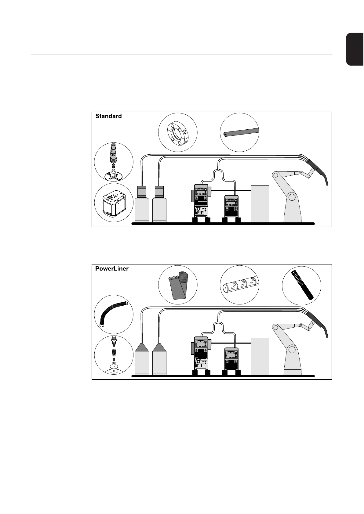
Standard and
PowerLiner variants
The welding wire can be fed in two different ways with the Drive EasyTwin process.
With the Standard variant, the welding wire is fed from the drum in the direction of the Robacta Drive EasyTwin by means of a wirefeeder. The wirefeeding hose is connected to the
hosepack by a special holder and hung up using spring balancer suspension devices.
With the PowerLiner variant, the welding wire is fed directly from the drum in the direction
of the Robacta Drive EasyTwin. The PowerLiner hose is connected to the hosepack by a
Velcro® strap and hung up using spring balancer suspension devices.
7

Installing the
1
2
4
6
CrashBox Drive
EasyTwin on the
robot
1 2
3 4
3
5 6
5
8
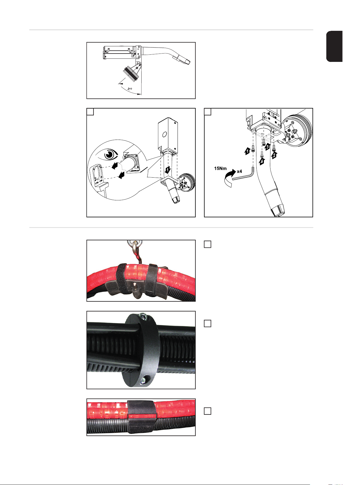
Attaching the
2
1
2
2
torch neck
Possible tilt angles:
EN
x = 5° / 25° / 45° / 65°
1 2
1
Securing the
hosepack to the
spring balancer
suspension devices
Secure the hosepack to the spring balancer suspension devices using Velcro® fasteners
- In the case of a 6 m hosepack >
use at least 3 suitably positioned
spring balancer suspension devices
Standard variant
Secure the wirefeeding hose to the hosepack at a distance of approx 50 cm
using a holder (item number:
44,0350,3952).
Important! The wirefeeding hose must
be secured to the hosepack using a
holder 20 cm before the Robacta Drive
EasyTwin unit.
PowerLiner variant
Secure the PowerLiner to the hosepack at a distance of approx 50 cm
using Velcro® fasteners (item number:
42,0300,2589).
9

Bring the PowerLiner into position at
3
2
5
8
2
the interface to the Robacta Drive EasyTwin using a Velcro® fastener
Connecting the
hosepack
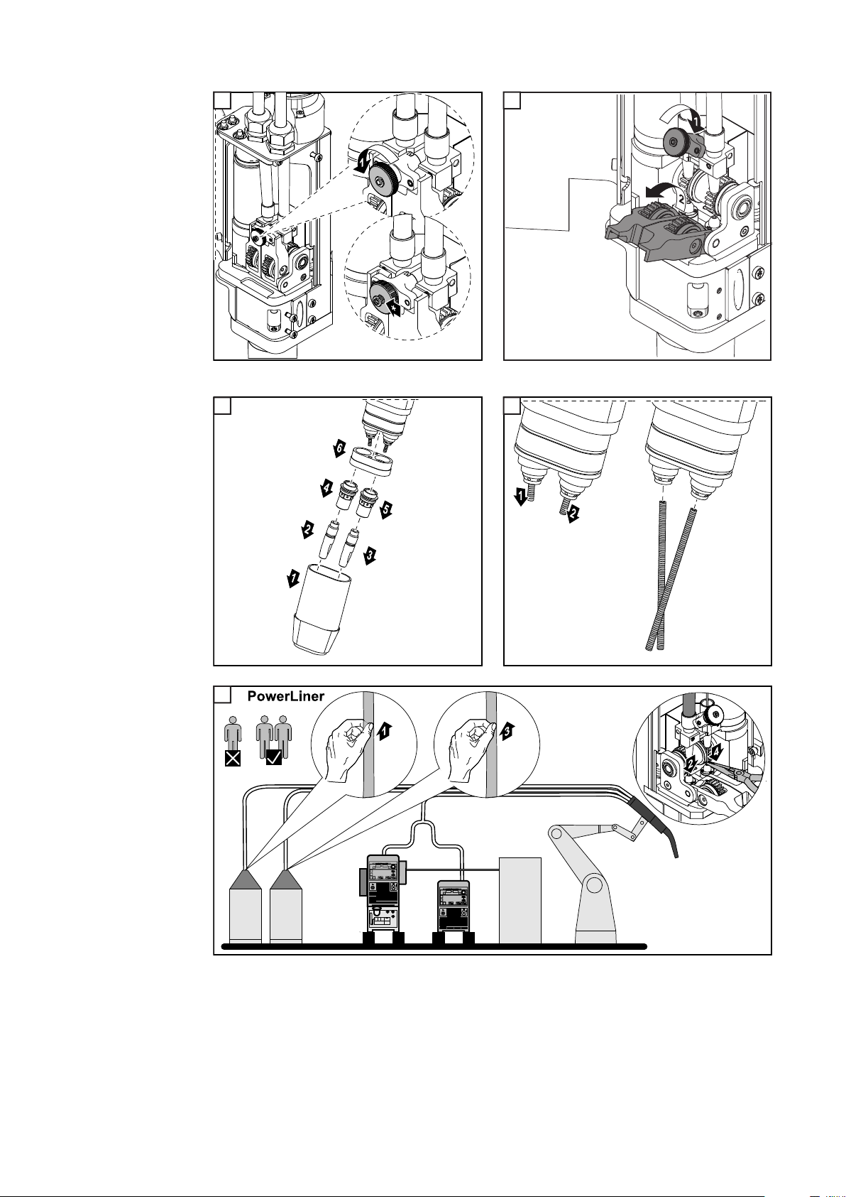
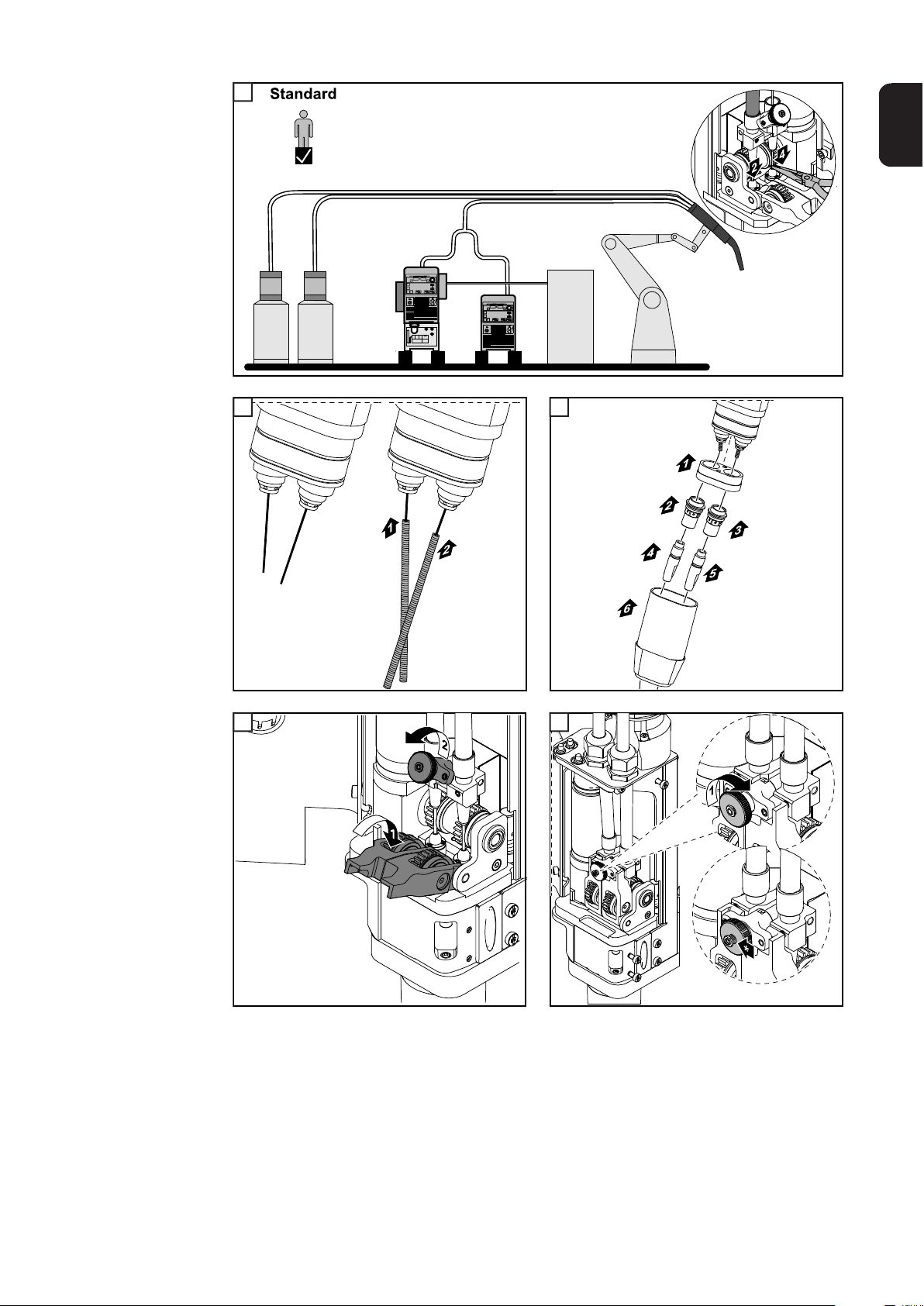
Installing the
wirefeeding hose
in the Robacta
Drive EasyTwin
Connect the lead hosepack (the gas purging line and the gas line are only contained
1
in the leading hosepack) to the lead power source (where the control box is mounted)
Connect the trail power cable (control line is only contained in the trail hosepack) to
the trail power source
Connect the coolant lines to the cooling unit
3
Connect the gas purging line to the control box
4
Connect the gas line to the control box
Connect the control line to the control box
6
Connect the LocalNet line to the control box and trail power source
7
Connect the compressed air line to the control box
Connect the gas feed to the control box (min. 30 l/min)
9
The wirefeeding hose must only be fitted when using the device for the first time.
1 2
1
10

3 4
4
2
3
Now the welding wire must be threaded (see "Threading the welding wire" from Figure 3
on page 12)
EN
Threading the
welding wire
NOTE!
For technical reasons, only the inner liners provided in the original equipment kit
must be used.
1 2
1
11
3
4
5
6
7
3
* Fully open
5 6
4
7
12
1
8
9
10
11
7
2 3
EN
4 5
*** Set the contact pressure (3 rings must be visible)
13

6 7
13
12
14

Safety rules
General The device is manufactured using state-of-the-art technology and according to recognised
safety standards. If used incorrectly or misused, however, it can cause:
- injury or death to the operator or a third party,
- damage to the device and other material assets belonging to the operating company,
- inefficient operation of the device.
All persons involved in commissioning, operating, maintaining and servicing the device
must:
- be suitably qualified,
- have sufficient knowledge of welding and
- read and follow these operating instructions carefully.
The operating instructions must always be at hand wherever the device is being used. In
addition to the operating instructions, attention must also be paid to any generally applicable and local regulations regarding accident prevention and environmental protection.
All safety and danger notices on the device
- must be in a legible state,
- must not be damaged,
- must not be removed,
- must not be covered, pasted or painted over.
EN
For the location of the safety and danger notices on the device, refer to the section headed
"General" in the operating instructions for the device.
Before switching on the device, rectify any faults that could compromise safety.
This is for your personal safety!
Proper use The device is to be used exclusively for its intended purpose.
The device is intended solely for the welding processes specified on the rating plate.
Any use above and beyond this purpose is deemed improper. The manufacturer shall not
be held liable for any damage arising from such usage.
Proper use includes:
- carefully reading and following all the instructions given in the operating instructions
- studying and obeying all safety and danger notices carefully
- performing all stipulated inspection and maintenance work.
Never use the device for the following purposes:
- Thawing out pipes
- Charging batteries
- Starting engines
The device is designed for use in industry and the workshop. The manufacturer accepts
no responsibility for any damage caused through use in a domestic setting.
Environmental
conditions
The manufacturer likewise accepts no liability for inadequate or incorrect results.
Operation or storage of the device outside the stipulated area will be deemed as not in accordance with the intended purpose. The manufacturer shall not be held liable for any damage arising from such usage.
15

Ambient temperature range:
- during operation: -10 °C to + 40 °C (14 °F to 104 °F)
- during transport and storage: -20 °C to +55 °C (-4 °F to 131 °F)
Relative humidity:
- up to 50% at 40 °C (104 °F)
- up to 90% at 20 °C (68 °F)
The surrounding air must be free from dust, acids, corrosive gases or substances, etc.
Can be used at altitudes of up to 2000 m (6561 ft. 8.16 in.)
Obligations of the
operator
The operator must only allow persons to work with the device who:
- are familiar with the fundamental instructions regarding safety at work and accident
prevention and have been instructed in how to use the device
- have read and understood these operating instructions, especially the section "safety
rules", and have confirmed as much with their signatures
- are trained to produce the required results.
Checks must be carried out at regular intervals to ensure that operators are working in a
safety-conscious manner.
Obligations of
personnel
Before using the device, all persons instructed to do so undertake:
- to observe the basic instructions regarding safety at work and accident prevention
- to read these operating instructions, especially the "Safety rules" section and sign to
confirm that they have understood them and will follow them.
Before leaving the workplace, ensure that people or property cannot come to any harm in
your absence.
Mains connection Devices with a higher rating may affect the energy quality of the mains due to their current
consumption.
Protecting yourself and others
This may affect a number device types in terms of:
- Connection restrictions
- Criteria with regard to the maximum permissible mains impedance
- Criteria with regard to the minimum short-circuit power requirement
*)
at the interface with the public grid
*)
*)
see "Technical data"
In this case, the plant operator or the person using the device should check whether the
device may be connected, where appropriate by discussing the matter with the power supply company.
IMPORTANT! Ensure that the mains connection is earthed properly
Anyone working with the device exposes themselves to numerous risks, e.g.
- flying sparks and hot pieces of metal
- Arc radiation, which can damage eyes and skin
- Hazardous electromagnetic fields, which can endanger the lives of those using cardiac pacemakers
- Risk of electrocution from mains current and welding current
- Greater noise pollution
- Harmful welding fumes and gases
16

Suitable protective clothing must be worn when working with the device. The protective
clothing must have the following properties:
- Flame-resistant
- Insulating and dry
- Covers the whole body, is undamaged and in good condition
- Safety helmet
- Trousers with no turn-ups
Protective clothing refers to a variety of different items. Operators should:
- Protect eyes and face from UV rays, heat and sparks using a protective visor and regulation filter
- Wear regulation protective goggles with side protection behind the protective visor
- Wear stout footwear that provides insulation even in wet conditions
- Protect the hands with suitable gloves (electrically insulated and providing protection
against heat)
- Wear ear protection to reduce the harmful effects of noise and to prevent injury
Keep all persons, especially children, out of the working area while any devices are in operation or welding is in progress. If, however, there are people in the vicinity:
- Make them aware of all the dangers (risk of dazzling by the arc, injury from flying
sparks, harmful welding fumes, noise, possible risks from mains current and welding
current, etc.)
- Provide suitable protective equipment
- Alternatively, erect suitable safety screens/curtains.
EN
Noise emission
values
Danger from toxic
gases and vapours
The device generates a maximum sound power level of <80 dB(A) (ref. 1pW) when idling
and in the cooling phase following operation at the maximum permissible operating point
under maximum rated load conditions according to EN 60974-1.
It is not possible to provide a workplace-related emission value during welding (or cutting)
as this is influenced by both the process and the environment. All manner of different welding parameters come into play, including the welding process (MIG/MAG, TIG welding), the
type of power selected (DC or AC), the power range, the type of weld metal, the resonance
characteristics of the workpiece, the workplace environment, etc.
The fumes produced during welding contain harmful gases and vapours.
Welding fumes contain substances that cause cancer, as stated in Monograph 118 of the
International Agency for Research on Cancer.
Use at-source extraction and a room extraction system.
If necessary, use a welding torch with an integrated extraction device.
Keep your face away from welding fumes and gases.
Fumes and hazardous gases
- must not be breathed in
- must be extracted from the working area using appropriate methods.
Ensure an adequate supply of fresh air. Ensure that there is a ventilation rate of at least
20 m³ per hour at all times.
Otherwise, a welding helmet with an air supply must be worn.
If there is any doubt about whether the extraction capacity is sufficient, the measured toxic
emission values should be compared with the permissible limit values.
17

The following components are responsible, amongst other things, for the degree of toxicity
of welding fumes:
- Metals used for the workpiece
- Electrodes
- Coatings
- Cleaners, degreasers, etc.
- Welding process used
The relevant material safety data sheets and manufacturer's specifications for the listed
components should therefore be studied carefully.
Recommendations for trade fair scenarios, risk management measures and for identifying
working conditions can be found on the European Welding Association website under
Health & Safety (https://european-welding.org).
Flammable vapours (e.g. solvent fumes) should be kept away from the arc's radiation area.
Close the shielding gas cylinder valve or main gas supply if no welding is taking place.
Danger from flying sparks
Risks from mains
current and welding current
Flying sparks may cause fires or explosions.
Never weld close to flammable materials.
Flammable materials must be at least 11 metres (36 ft. 1.07 in.) away from the arc, or al-
ternatively covered with an approved cover.
A suitable, tested fire extinguisher must be available and ready for use.
Sparks and pieces of hot metal may also get into adjacent areas through small gaps or
openings. Take appropriate precautions to prevent any danger of injury or fire.
Welding must not be performed in areas that are subject to fire or explosion or near sealed
tanks, vessels or pipes unless these have been prepared in accordance with the relevant
national and international standards.
Do not carry out welding on containers that are being or have been used to store gases,
propellants, mineral oils or similar products. Residues pose an explosive hazard.
An electric shock is potentially life threatening and can be fatal.
Do not touch live parts either inside or outside the device.
During MIG/MAG welding and TIG welding, the welding wire, the wirespool, the feed rollers
and all pieces of metal that are in contact with the welding wire are live.
18
Always set the wirefeeder up on a sufficiently insulated surface or use a suitable, insulated
wirefeeder holder.
Make sure that you and others are protected with an adequately insulated, dry base or cover for the earth or ground potential. This base or cover must extend over the entire area
between the body and the earth or ground potential.
All cables and leads must be secured, undamaged, insulated and adequately dimensioned. Replace loose connections and scorched, damaged, or inadequately dimensioned
cables and leads immediately.
Use the handle to ensure the power connections are tight before every use.
In the case of power cables with a bayonet connector, rotate the power cable around the
longitudinal axis by at least 180° and pretension.
Do not wrap cables or leads around the body or parts of the body.

The electrode (rod electrode, tungsten electrode, welding wire, etc.) must
- never be immersed in liquid for cooling
- Never touch the electrode when the power source is switched on.
Double the open circuit voltage of a power source can occur between the welding electrodes of two power sources. Touching the potentials of both electrodes at the same time
may be fatal under certain circumstances.
Arrange for the mains cable to be checked regularly by a qualified electrician to ensure the
ground conductor is functioning properly.
Protection class I devices require a mains supply with ground conductor and a connector
system with ground conductor contact for proper operation.
Operation of the device on a mains supply without ground conductor and on a socket without ground conductor contact is only permitted if all national regulations for protective separation are observed.
Otherwise, this is considered gross negligence. The manufacturer shall not be held liable
for any damage arising from such usage.
If necessary, provide adequate earthing for the workpiece.
Switch off unused devices.
Wear a safety harness if working at height.
Before working on the device, switch it off and pull out the mains plug.
EN
Meandering welding currents
Attach a clearly legible and easy-to-understand warning sign to the device to prevent anyone from plugging the mains plug back in and switching it on again.
After opening the device:
- Discharge all live components
- Ensure that all components in the device are de-energised.
If work on live parts is required, appoint a second person to switch off the main switch at
the right moment.
If the following instructions are ignored, meandering welding currents can develop with the
following consequences:
- Fire hazard
- Overheating of parts connected to the workpiece
- Irreparable damage to ground conductors
- Damage to device and other electrical equipment
Ensure that the workpiece is held securely by the workpiece clamp.
Attach the workpiece clamp as close as possible to the area that is to be welded.
Position the device with sufficient insulation against electrically conductive environments,
e.g. Insulation against conductive floor or insulation to conductive racks.
If distribution boards, twin-head mounts, etc., are being used, note the following: The electrode of the welding torch / electrode holder that is not used is also live. Make sure that the
welding torch / electrode holder that is not used is kept sufficiently insulated.
In the case of automated MIG/MAG applications, ensure that only an insulated wire electrode is routed from the welding wire drum, large wirefeeder spool or wirespool to the wirefeeder.
19

EMC Device Classifications
EMC measures In certain cases, even though a device complies with the standard limit values for emis-
Devices in emission class A:
- Are only designed for use in industrial settings
- Can cause line-bound and radiated interference in other areas
Devices in emission class B:
- Satisfy the emissions criteria for residential and industrial areas. This is also true for
residential areas in which the energy is supplied from the public low-voltage mains.
EMC device classification as per the rating plate or technical data.
sions, it may affect the application area for which it was designed (e.g. when there is sensitive equipment at the same location, or if the site where the device is installed is close to
either radio or television receivers).
If this is the case, then the operator is obliged to take appropriate action to rectify the situation.
Check and evaluate the immunity to interference of nearby devices according to national
and international regulations. Examples of equipment that may be susceptible to interference from the device include:
- Safety devices
- Power, signal and data transfer lines
- IT and telecommunications devices
- Measuring and calibrating devices
Supporting measures for avoidance of EMC problems:
1. Mains supply
- If electromagnetic interference arises despite correct mains connection, addition-
al measures are necessary (e.g. use a suitable line filter).
2. Welding power leads
- must be kept as short as possible
- must run close together (to avoid EMF problems)
- must be kept well apart from other leads
3. Equipotential bonding
4. Earthing of the workpiece
- If necessary, establish an earth connection using suitable capacitors.
5. Shielding, if necessary
- Shield off other nearby devices
- Shield off entire welding installation
EMF measures Electromagnetic fields may pose as yet unknown risks to health:
- effects on the health of others in the vicinity, e.g. wearers of pacemakers and hearing
aids
- wearers of pacemakers must seek advice from their doctor before approaching the device or any welding that is in progress
- for safety reasons, keep distances between the welding cables and the welder's head/
torso as large as possible
- do not carry welding cables and hosepacks over the shoulders or wind them around
any part of the body
20

Specific hazards Keep hands, hair, clothing and tools away from moving parts. For example:
- Fans
- Cogs
- Rollers
- Shafts
- Wirespools and welding wires
Do not reach into the rotating cogs of the wire drive or into rotating drive components.
Covers and side panels may only be opened/removed while maintenance or repair work is
being carried out.
During operation
- Ensure that all covers are closed and all side panels are fitted properly.
- Keep all covers and side panels closed.
The welding wire emerging from the welding torch poses a high risk of injury (piercing of
the hand, injuries to the face and eyes, etc.).
Therefore always keep the welding torch away from the body (devices with wire-feed unit)
and wear suitable protective goggles.
Never touch the workpiece during or after welding - risk of burns.
Slag can jump off cooling workpieces. The specified protective equipment must therefore
also be worn when reworking workpieces, and steps must be taken to ensure that other
people are also adequately protected.
EN
Welding torches and other parts with a high operating temperature must be allowed to cool
down before handling.
Special provisions apply in areas at risk of fire or explosion - observe relevant
national and international regulations.
Power sources for work in areas with increased electric risk (e.g. near boilers) must carry
the "Safety" sign. However, the power source must not be located in such areas.
Risk of scalding from escaping coolant. Switch off cooling unit before disconnecting coolant flow or return lines.
Observe the information on the coolant safety data sheet when handling coolant. The coolant safety data sheet may be obtained from your service centre or downloaded from the
manufacturer's website.
Use only suitable load-carrying equipment supplied by the manufacturer when transporting
devices by crane.
- Hook chains and/or ropes onto all suspension points provided on the load-carrying
equipment.
- Chains and ropes must be at the smallest angle possible to the vertical.
- Remove gas cylinder and wire-feed unit (MIG/MAG and TIG devices).
If the wire-feed unit is attached to a crane holder during welding, always use a suitable,
insulated wirefeeder hoisting attachment (MIG/MAG and TIG devices).
If the device has a carrying strap or handle, this is intended solely for carrying by hand. The
carrying strap is not to be used if transporting with a crane, counterbalanced lift truck or
other mechanical hoist.
All lifting accessories (straps, handles, chains, etc.) used in connection with the device or
its components must be tested regularly (e.g. for mechanical damage, corrosion or changes caused by other environmental factors).
The testing interval and scope of testing must comply with applicable national standards
and directives as a minimum.
21

Odourless and colourless shielding gas may escape unnoticed if an adapter is used for the
shielding gas connection. Prior to assembly, seal the device-side thread of the adapter for
the shielding gas connection using suitable Teflon tape.
Requirement for
the shielding gas
Danger from
shielding gas cylinders
Especially with ring lines, contaminated shielding gas can cause damage to equipment and
reduce welding quality.
Meet the following requirements regarding shielding gas quality:
- Solid particle size < 40 µm
- Pressure condensation point < -20 °C
- Max. oil content < 25 mg/m³
Use filters if necessary.
Shielding gas cylinders contain gas under pressure and can explode if damaged. As the
shielding gas cylinders are part of the welding equipment, they must be handled with the
greatest of care.
Protect shielding gas cylinders containing compressed gas from excessive heat, mechanical impact, slag, naked flames, sparks and arcs.
Mount the shielding gas cylinders vertically and secure according to instructions to prevent
them falling over.
Keep the shielding gas cylinders well away from any welding or other electrical circuits.
Never hang a welding torch on a shielding gas cylinder.
Never touch a shielding gas cylinder with an electrode.
Safety measures
at the installation
location and during transport
Risk of explosion - never attempt to weld a pressurised shielding gas cylinder.
Only use shielding gas cylinders suitable for the application in hand, along with the correct
and appropriate accessories (regulator, hoses and fittings). Only use shielding gas cylinders and accessories that are in good condition.
Turn your face to one side when opening the valve of a shielding gas cylinder.
Close the shielding gas cylinder valve if no welding is taking place.
If the shielding gas cylinder is not connected, leave the valve cap in place on the cylinder.
The manufacturer's instructions must be observed as well as applicable national and inter-
national regulations for shielding gas cylinders and accessories.
A device toppling over could easily kill someone. Place the device on a solid, level surface
such that it remains stable
- The maximum permissible tilt angle is 10°.
Special regulations apply in rooms at risk of fire or explosion
- Observe relevant national and international regulations.
Use internal directives and checks to ensure that the workplace environment is always
clean and clearly laid out.
22
Only set up and operate the device in accordance with the degree of protection shown on
the rating plate.
When setting up the device, ensure there is an all-round clearance of 0.5 m (1 ft. 7.69 in.)
to ensure that cooling air can flow in and out freely.

When transporting the device, observe the relevant national and local guidelines and accident prevention regulations. This applies especially to guidelines regarding the risks arising during transport.
Do not lift or transport operational devices. Switch off devices before transport or lifting.
Before transporting the device, allow coolant to drain completely and detach the following
components:
- Wirefeeder
- Wirespool
- Shielding gas cylinder
After transporting the device, the device must be visually inspected for damage before
commissioning. Any damage must be repaired by trained service technicians before commissioning the device.
EN
Safety measures
in normal operation
Only operate the device when all safety devices are fully functional. If the safety devices
are not fully functional, there is a risk of
- injury or death to the operator or a third party
- damage to the device and other material assets belonging to the operator
- inefficient operation of the device
Any safety devices that are not functioning properly must be repaired before switching on
the device.
Never bypass or disable safety devices.
Before switching on the device, ensure that no one is likely to be endangered.
Check the device at least once a week for obvious damage and proper functioning of safety
devices.
Always fasten the shielding gas cylinder securely and remove it beforehand if the device
is to be transported by crane.
Only the manufacturer's original coolant is suitable for use with our devices due to its properties (electrical conductibility, anti-freeze agent, material compatibility, flammability, etc.).
Only use suitable original coolant from the manufacturer.
Do not mix the manufacturer's original coolant with other coolants.
Only connect the manufacturer's system components to the cooling circuit.
The manufacturer accepts no liability for damage resulting from use of other system com-
ponents or a different coolant. In addition, all warranty claims will be forfeited.
Cooling Liquid FCL 10/20 does not ignite. The ethanol-based coolant can ignite under cer-
tain conditions. Transport the coolant only in its original, sealed containers and keep well
away from any sources of ignition.
Used coolant must be disposed of properly in accordance with the relevant national and
international regulations. The coolant safety data sheet may be obtained from your service
centre or downloaded from the manufacturer's website.
Check the coolant level before starting to weld, while the system is still cool.
23

Commissioning,
maintenance and
repair
Safety inspection The manufacturer recommends that a safety inspection of the device is performed at least
It is impossible to guarantee that bought-in parts are designed and manufactured to meet
the demands made of them, or that they satisfy safety requirements.
- Use only original spare and wearing parts (also applies to standard parts).
- Do not carry out any modifications, alterations, etc. to the device without the manufacturer's consent.
- Components that are not in perfect condition must be replaced immediately.
- When ordering, please give the exact designation and part number as shown in the
spare parts list, as well as the serial number of your device.
The housing screws provide the ground conductor connection for earthing the housing
parts.
Only use original housing screws in the correct number and tightened to the specified
torque.
once every 12 months.
The manufacturer recommends that the power source be calibrated during the same 12month period.
A safety inspection should be carried out by a qualified electrician
- after any changes are made
- after any additional parts are installed, or after any conversions
- after repair, care and maintenance has been carried out
- at least every twelve months.
For safety inspections, follow the appropriate national and international standards and directives.
Further details on safety inspection and calibration can be obtained from your service centre. They will provide you on request with any documents you may require.
Disposal Do not dispose of this device with normal domestic waste! To comply with the European
Directive on Waste Electrical and Electronic Equipment and its implementation as national
law, electrical equipment that has reached the end of its life must be collected separately
and returned to an approved recycling facility. Any device that you no longer require must
either be returned to your dealer or given to one of the approved collection and recycling
facilities in your area. Ignoring this European Directive may have potentially adverse affects on the environment and your health!
Safety symbols Devices with the CE mark satisfy the essential requirements of the low-voltage and elec-
tromagnetic compatibility directives (e.g. relevant product standards of the EN 60 974 series).
Fronius International GmbH hereby declares that the device is compliant with Directive
2014/53/EU. The full text on the EU Declaration of Conformity can be found at the following
address: http://www.fronius.com
Devices marked with the CSA test mark satisfy the requirements of the relevant standards
for Canada and the USA.
Data protection The user is responsible for the safekeeping of any changes made to the factory settings.
The manufacturer accepts no liability for any deleted personal settings.
24

Copyright Copyright of these operating instructions remains with the manufacturer.
The text and illustrations are all technically correct at the time of printing. We reserve the
right to make changes. The contents of the operating instructions shall not provide the basis for any claims whatsoever on the part of the purchaser. If you have any suggestions for
improvement, or can point out any mistakes that you have found in the instructions, we will
be most grateful for your comments.
EN
25

General
Regarding these
operating instructions
Comparison of
Drive EasyTwin
with TimeTwin
Digital
These operating instructions describe the "Drive EasyTwin" process.
In general, a distinction is made between the following according to DVS data sheet 0909
- Part 1
- Double-wire welding: Welding of two wire electrodes with the same welding potential
- Tandem welding (Fronius: TimeTwin Digital): Welding of two wire electrodes with separate welding potential
TimeTwin Digital Drive EasyTwin
Welding potential Separate Separate
Arc can be controlled selectively Yes Yes
Arc length can be set selectively Yes Yes
Arc blow during pulsed arc Low Low
Spattering Low Low
Pulsed/pulsed arc combination Possible Possible
Pulsed/standard arc combination Possible Possible
Standard/pulsed arc combination Possible Possible
Standard/standard arc combination Possible *) Possible *)
Wirefeeder can be controlled separately Yes No
Drive EasyTwin
advantages
Drive EasyTwin
functional principle
*) is not recommended
- Thanks to the frontpull drive, there is no slip in the hosepack. This results in a stable
arc
- Few wearing parts - low maintenance costs
- The system is completely free from inner liners up to the torch neck
- Simple design - smaller robot size needed
- Easy to adjust the power source characteristic to the base and filler metal as well as
to the shielding gas
- Small weld pool due to short arc - which results in a high welding speed
- Mixed operation is possible (e.g.: pulsed arc/standard arc)
- Easy operation as it shares the same menu navigation as the TPS 4000/5000
- Two wire electrodes are welded in a weld pool under a shielding gas environment.
- The wire is fed via a shared frontpull drive.
- The frontpull drive is controlled via a control unit.
- Both wire electrodes are brought together in the welding torch in such a way that two
independent welding potentials are available.
- The Drive EasyTwin process only works when used with filler metal from drums.
26

(1)
(1)
(2)
EN
Lead power
source and trail
power source
(3)
(3)
(4) (4)
(1) Wirefeeding hose 1 and 2
(2) Wire drum 1 and 2
(3) Power source 1 and 2
(4) Separate welding potential
The two power sources are referred to as the lead power source and the trail power source
in the "Drive EasyTwin" process.
- The welding direction is defined by the wire pairing.
- The wire electrode of the lead power source is the front wire electrode, in terms of the
welding direction.
Drive EasyTwin
application areas
Dimensioning of
the robot
Drive EasyTwin is only used for automated applications, e.g.:
- In rolling stock manufacturing for longitudinal seams and profiles
- In shipbuilding for fillet welds and profiles
- In vehicle manufacturing for lap joints and welding wheel rims
- In container construction for butt welds, longitudinal seams, lap joints and circumferential welds
- In plant construction for V, X and fillet welds
- For edge welds on lifting gear
- For HV and fillet welds on earth-moving machines and in special machine construction
- For overlay welding
Please note the following when dimensioning the robot:
- The torch holder on the robot must be stable. The Drive EasyTwin welding torch with
CrashBox weighs ??? kg.
- The robot hose pack and wirefeeding hoses must be routed via a balancer in the robot
cell.
27

Welding torch
cleaning station
A welding torch cleaning station is recommended to ensure optimum performance of the
automated Drive EasyTwin welding process, for example:
Robacta Reamer Twin
Mechanical torch cleaning device, suitable for all base materials, such as steel, aluminium,
CrNi steels, copper, etc.
Robacta TC 1000 Twin or Robacta TC 2000 Twin
Electromagnetic torch cleaning device for ferromagnetic base materials.
28

System requirements
System requirements and minimum equipment
for Drive EasyTwin
EN
Welding torch:
1 x Robacta Twin Compact PB ED
Drive:
1 x Robacta Drive EasyTwin
Torch hosepack:
1 x Robacta Drive EasyTwin W/FB
Drive EasyTwin
mechanical requirements
gas line /
blow out line
LEADING TRAILING
For a stable and reproducible "Drive EasyTwin" process, the following mechanical requirements must be met:
- Precise torch guidance for robots or single-purpose machines (e.g. straight-line carriage)
- Exact joint preparation
- Low component tolerances
- Seam guidance system with low deviation
- Due to the system, a wirefeeder is not required on the 3rd shaft
control line
Power sources:
2 x TPS 5000 (+ variants)
1 x control unit
Cooling unit:
1 x FK 4000-R FC
29

Control elements and connections
(3)
(1) (2)
Drive EasyTwin
drive unit controls
No. Function
(1) Gas-test button
for setting the required gas flow rate on the pressure regulator
(2) Wire threading button
to thread the wire electrode into the torch hosepack with no accompanying flow
of gas or current
Thread the wire electrode using the preset feeder inching speed:
NOTE!
Do not allow long lengths of wire electrode to be retracted, as the wire electrode is
not automatically wound up when retracted.
No. Function
(3) Wire retract button
The wire retract button only works with the PowerLiner variant.
Retraction of wire electrode without accompanying flow of gas or current
Retract the wire electrode using the preset wire retract speed
30

Welding technology aspects
EN
Shielding gases
for Drive EasyTwin
Gas flow for Drive
EasyTwin
Earth connection Use a separate grounding (earthing) cable for each power source:
Material Shielding gas
Unalloyed and low-alloy steels ArCO
- Total gas flow rate at least 30 l/min
NOTE!
Due to the reduced setting options (synchronisation), we recommend shielding gases with a low active proportion of shielding gas, e.
g. 96% argon/4% oxygen or 90% argon/10% CO2. This results in less spattering and, in
turn, considerably less wear.
, ArO2 and ArCO2O2 compounds
2
Welding circuit
inductivity L,
welding circuit resistance r
Separate grounding (earthing) cable Shared grounding (earthing) cable, earth socket
Grounding (earthing) cable laid in a loop Grounding (earthing) cable coiled
The welding circuit inductivity L and the welding circuit resistance r must be calibrated separately for each power source for the "Drive EasyTwin" process.
31
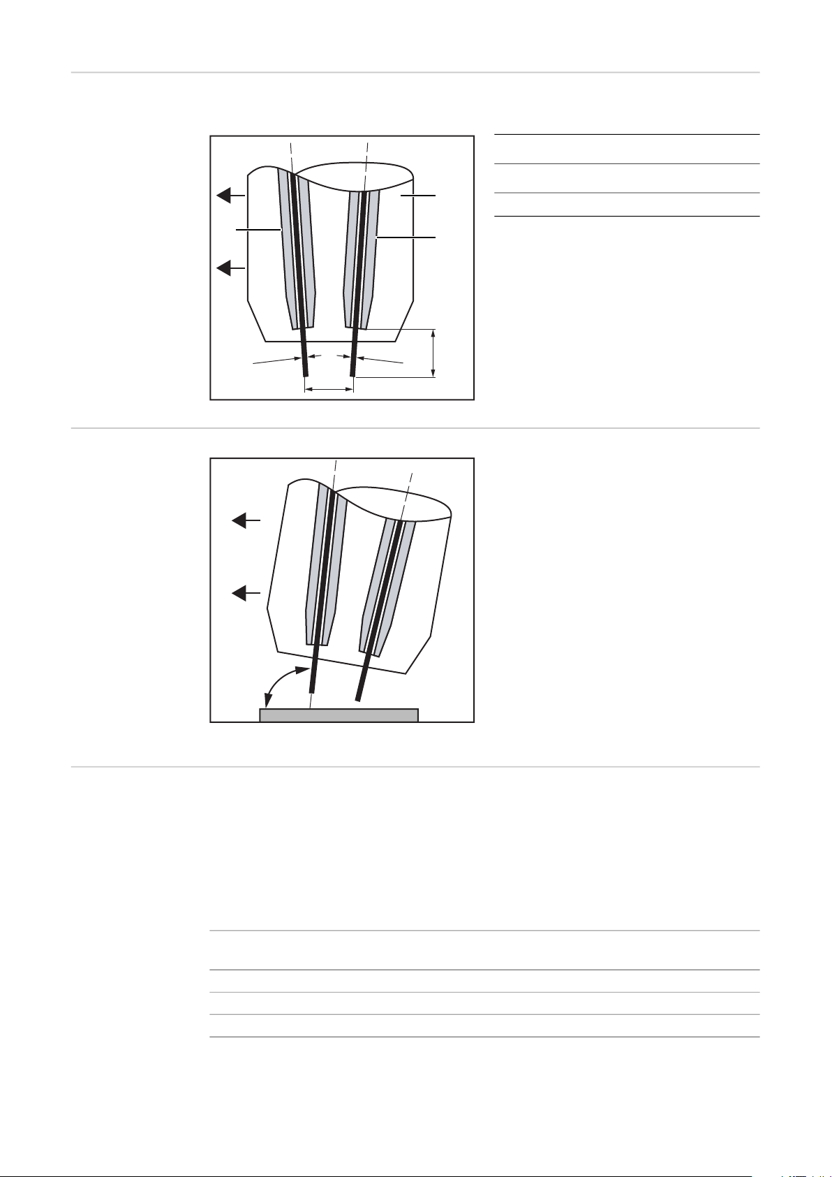
Stick out Stick out and spacing of the wire electrodes:
Ø 1,2 mm
Ø 1,0 mm
18 mm
~8 mm
(1)
(2)
(3)
90 - 100°
(1) Gas nozzle
(2) Trail power source
(3) Lead power source
Tilt angle of the
welding torch
Arc combination
options
Select the welding torch tilt angle so that,
depending on the direction of welding, the
lead wire electrode (= the electrode of the
lead power source) is positioned neutrally
or slightly forward.
Welding torch tilt angle neutral to slightly forward
Different arc types can be combined in the "Drive EasyTwin" process.
The welding direction is defined by the wire pairing (Ø 1.2 mm lead power source/Ø 1.0
trail power source) and the construction of the welding torch.
32
The arc combination option pulsed - pulsed is only possible with the LHSB TPS installation
kit.
Lead wire electrode
(= lead power source)
Pulse Pulse
Standard Pulse
Trail wire electrode
(= trail power source)
PCS Pulse
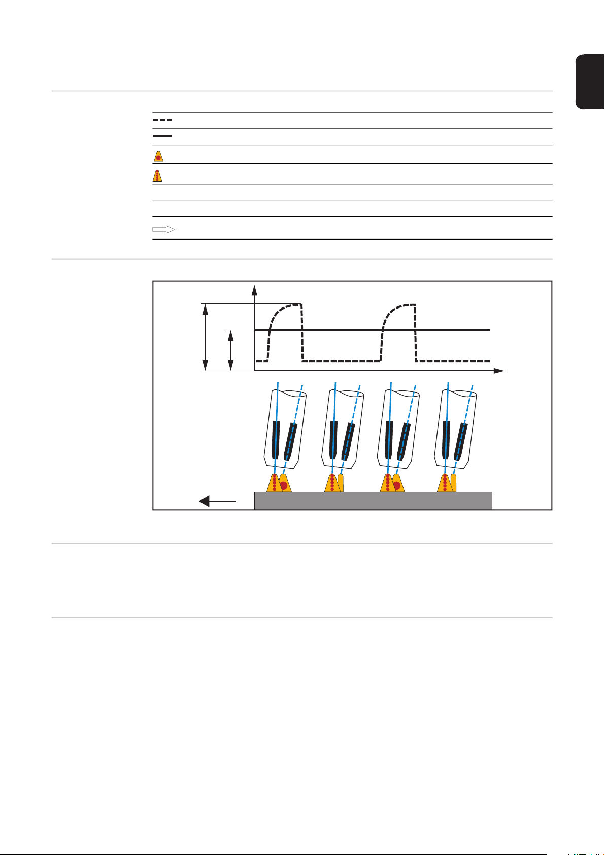
PCS/pulsed
I (A)
t (s)
I
T
I
L
EN
Symbols
Material transfer
Trail wire electrode
Lead wire electrode
Active pulsed arc with droplet transfer
Inactive pulsed arc (no droplet transfer)
I
L
I
T
Welding current of lead power source
Welding current of trail power source
Welding direction
Special features
and advantages
Potential applications, area of application
PCS/pulsed: Welding current/time curve and schematic representation of the material transfer
- Greater penetration by the PCS arc of the lead wire electrode
- Large seam cross-sections possible
- Visually excellent weld seams thanks to the pulsed arc of the trail wire electrode
The PCS/pulsed arc combination is used for steel applications.
33
Welding parameter standard values
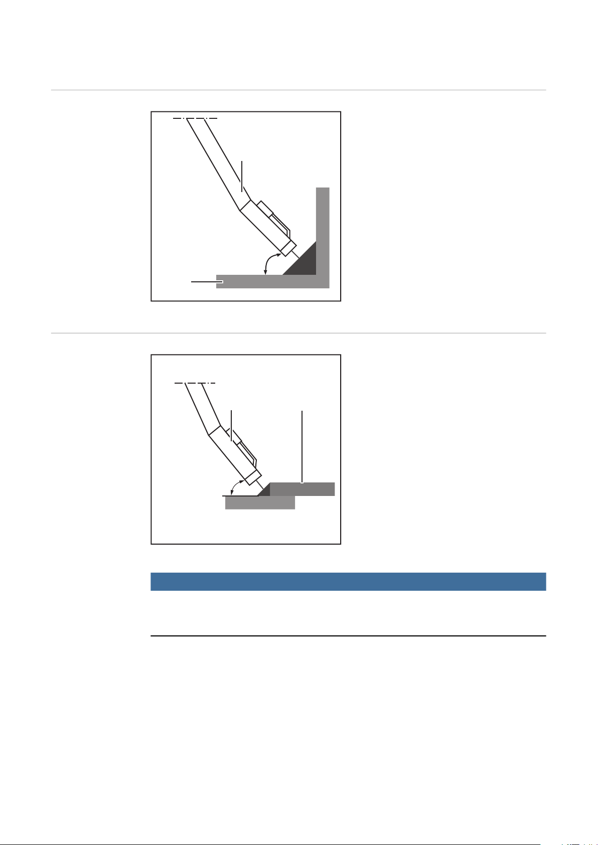
35 - 40°
(1)
(2)
55 - 75°
(1)
(2)
Alignment of
welding torch relative to the workpiece for fillet
welds
Alignment of
welding torch relative to the workpiece for lap
joints
- Align welding torch (1) relative to the
workpiece (2) as shown on the lefthand figure
- Welding torch (1) at a 5° angle to the
welding direction
Side view of welding torch/workpiece
- Align welding torch (1) relative to the
workpiece (2) as shown on the lefthand figure
- Welding torch (1) at a 5° angle to the
welding direction
34
Side view of welding torch/workpiece
NOTE!
If notches appear in the weld seam on the top sheet, adopting the welding torch
alignment shown below can prevent these notches from occurring.
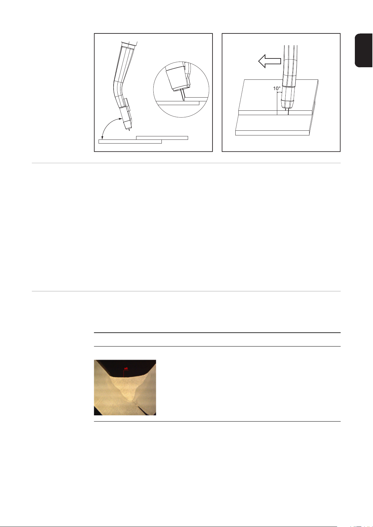
EN
68,5°
Area of application for Drive EasyTwin - steel,
diameter 1.2 mm -
1.0 mm
Welding technology options
The Drive EasyTwin characteristic range covers Vd. = 5 m/min (one power source) to Vd.
= 15 m/min.
This range is determined by the following
- The filler metal 1.0 is the absolute upper load capacity limit at Vd. = 15 m/min
- As there is only one wire-feed motor, this is protected from overload
The working range is Vd. = 10.5 m/min to Vd. = 15 m/min.
The Vd. range below 10 m/min. is only intended for up and downslope.
The range from Vd. = 8.5 m/min to Vd.= 10.5 m/min is a transition range in which the 1.2
mm filler metal (lead power source) changes to a modified spray arc. This change occurs
at Vd. = 9 m/min or Vd. = 10 m/min depending on the shielding gas used (characteristic).
This range should be avoided as a production parameter.
IMPORTANT!
The weld seam length is limited to a maximum of 5 m for all the applications listed.
Single layer fillet welds/PA position:
Sheet thickness: from 3 mm
a-dimension single
a3 - a6
layer:
a3: Vs-2 m/min
a6: Vs-0.5 m/min
If an a-dimension greater than 6 mm is required, then multi-lay-
er technology is recommended.
Single layer fillet welds/PB position:
35

Sheet thickness: from 3 mm
a-dimension single
layer:
a3: Vs-2 m/min
a4.5: Vs-1.2 m/min
If an a-dimension greater than 4.5 mm is required, then multilayer technology is recommended.
Multiple layer fillet welds/PB position:
Sheet thickness: from 3 mm
a-dimension multi-
ple layer:
Possible deposition rate: Up to 13.5 kg
Single layer edge welds/PA position:
Sheet thickness: 3 - 6 mm
Sheet thickness of 3
mm:
Sheet thickness of 6
mm:
Without pool support, 100% root formation is not possible.
a3 - a4.5
a3 - a4.5
Vs-3.2 m/min
Vs-1.8 m/min
Lap joints/PB position:
Sheet thickness (s): 1.5 - 2.5 mm
Sheet thickness of 2
mm:
Sheet thickness of
2.5 mm:
Lap joints/PB position:
Sheet thickness (s): 2.5 - 3.5 mm
Welding position as shown
The parameters listed here are standard values and may vary by up to +/- 20% in practice
due to factors relating to the join (magnetic fields, scale, etc.). Therefore, always carry out
a welding trial for borderline cases.
Vs-3.3 m/min
Vs-2.5 m/min
Vs-2 - 2.5 m/min
36

Care, maintenance and disposal
General The device generally needs no maintenance. However, to keep the device in good working
condition for years to come, several points on care and maintenance must be observed.
EN
Example: consumption of filler
metal
Before shift
starts/before
starting up
After 25 hours of
arc time
After 50 hours of
arc time
Sample calculation, consumption of steel filler metal:
Vd. speed = 12 m/min (filler metal 1.2 + 1.0) = 10.8 kg/h deposition rate -> rounded to 10
kg/h
At 50 hours of arc time:
10 kg/h x 50 h = 500 kg filler metal = 2 wire drums of 250 kg each
- Check the welding torch wearing parts:
- Gas nozzle
- Contact tip
- Gas distributor
- Spatter guard...
- Gas purge the inner liners
- Gas purge the Robacta Drive EasyTwin drive unit
- Check the feed rollers
If the feed rollers are worn, the axle block of the pressure rollers and the counter bearing
of the double roller must be replaced (see "Replacing wearing parts").
Disposal Dispose of in accordance with applicable national and local regulations.
37

Replacing wearing parts
2
4
6
Preparation
replacing the feed
rollers and
nozzle
1 2
1
3
3
4
* Fully open
5 6
5
38

7 8
8
10
12
7
9 10
9
EN
11 12
11
39

Replacing the in-
1
2
1
2
3
4
let nozzle
1 2
Now the welding wire must be threaded (see "Threading the welding wire" from Figure 5
on page 12)
Replacing the
feed rollers
1 2
3 4
40

5 6
6
5
Now the welding wire must be threaded (see "Threading the welding wire" from Figure 5
on page 12)
EN
41

42

EN
43

FRONIUS INTERNATIONAL GMBH
Froniusstraße 1
A-4643 Pettenbach
AUSTRIA
contact@fronius.com
www.fronius.com
Under www.fronius.com/contact you will find the addresses
of all Fronius Sales & Service Partners and locations.
 Loading...