

Page 1

Operating
Instructions
DeviceNet
DeviceNet Twin
Bedienungsanleitung
DE
Operating Instructions
EN
Instructions de service
FR
Návod na obsluhu
SK
Kullanım kılavuzu
TR
ZH
操作说明书
42,0410,0635 014-02032023
Page 2

Page 3

Inhaltsverzeichnis
Allgemeines 4
Sicherheit 4
Grundlagen 4
Gerätekonzept 4
Anschlüsse am Interface - TS/TPS, MW/TT Geräteserie 5
Zusatzhinweise 5
Anwendungsbeispiel - TS/TPS, MW/TT - Geräteserie 5
Hinweise zum Einbau der externen Variante des Interfaces 6
Feldbus-Koppler anschließen und konfigurieren 7
Sicherheit 7
Anschlüsse am Feldbus-Koppler 7
Feldbus-Koppler anschließen 7
Konfiguration Slave-Adresse BK5250 9
Konfiguration Baudrate BK5200 10
Eigenschaften der Datenübertragung 11
Übertragungstechnik 11
Sicherheitseinrichtung 11
Fehlerdiagnose, Fehlerbehebung 12
Sicherheit 12
Allgemeines 12
K-Bus / Betriebszustand LEDs (Lokale Fehler) 13
LEDs Feldbus-Status 14
Signalbeschreibung DeviceNet/DeviceNet Twin 15
Allgemeines 15
Betriebsarten der Stromquelle - TS/TPS, MW/TT Geräteserie 15
Übersicht 15
Ein- und Ausgangssignale für MIG/MAG - TS/TPS, MW/TT Geräteserie 16
Eingangssignale (vom Roboter zur Stromquelle) 16
Ausgangssignale (von der Stromquelle zum Roboter) 17
Ein- und Ausgangssignale für WIG - TS/TPS, MW/TT Geräteserie 19
Eingangssignale (vom Roboter zur Stromquelle) 19
Einstellung Pulsbereich WIG 20
Ausgangssignale (von der Stromquelle zum Roboter) 20
Ein- und Ausgangssignale für CC/CV - TS/TPS, MW/TT Geräteserie 22
Eingangssignale (vom Roboter zur Stromquelle) 22
Ausgangssignale (von der Stromquelle zum Roboter) 23
Ein- und Ausgangssignale für Standard-Manuell - TS/TPS, MW/TT Geräteserie 25
Eingangssignale (vom Roboter zur Stromquelle) 25
Ausgangssignale (von der Stromquelle zum Roboter) 26
Ein- und Ausgangssignale für MIG/MAG Twin Device-Net (4.100.400) - TS/TPS, MW/TT
Geräteserie
Eingangssignale (vom Roboter zur Stromquelle) 28
Ausgangssignale (von der Stromquelle zum Roboter) 29
Ein- und Ausgangssignale für MIG/MAG Twin Device-Net John Deere (4.100.400.800) - TS/
TPS, MW/TT Geräteserie
Eingangssignale (vom Roboter zur Stromquelle) 31
Ausgangssignale (von der Stromquelle zum Roboter) 32
Konfigurationsbeispiele 34
Allgemeines 34
Konfigurationsbeispiele 34
Technische Daten 37
DeviceNet-Koppler BK5250 37
DeviceNet-Koppler BK5200 38
Schaltpläne 39
DE
28
31
3
Page 4

Allgemeines
Sicherheit
Gefahr durch Fehlbedienung und fehlerhaft durchgeführte Arbeiten.
Schwere Personen- und Sachschäden können die Folge sein.
▶
▶
▶
Grundlagen DeviceNet ist ein offenes System das auf der Basis von CAN aufsetzt. CAN wur-
de vor einigen Jahren von der Firma R. Bosch für die Datenübertragung in Kraftfahrzeugen entwickelt. Seitdem sind Millionen von CAN-Chips im Einsatz. Nachteilig für einen Einsatz in der Automatisierungstechnik ist, dass CAN keine Definitionen für die Applikationsschicht enthält. CAN definiert nur die physikalische
und Datensicherungsschicht.
Mit DeviceNet ist eine einheitliche Applikationsschicht festgelegt, mit der das
CANProtokoll für Industrieanwendungen nutzbar wird. DIE ODVA (Open DeviceNet Vendor Association) unterstützt Hersteller und Anwender des Systems DeviceNet als unabhängiger Verein. Die ODVA stellt sicher, dass alle Geräte, die der
Spezifikation entsprechen, herstellerneutral zusammen in einem System arbeiten.
WARNUNG!
Alle in diesem Dokument beschriebenen Arbeiten und Funktionen dürfen
nur von technisch geschultem Fachpersonal ausgeführt werden.
Dieses Dokument vollständig lesen und verstehen.
Sämtliche Sicherheitsvorschriften und Benutzerdokumentationen dieses
Gerätes und aller Systemkomponenten lesen und verstehen.
CAN bietet durch das Verfahren der Bitarbitration grundsätzlich die Möglichkeit,
Kommunikationsnetze mit Master/Slave- und Multimaster- Zugriffsverfahren zu
betreiben. Der Buskoppler BK5200 mit dem Ausgabestand der Software B2 unterstützt den Master/Slave Betrieb (Polling Mode), wobei der Buskoppler als
Slave arbeitet. In späteren Ausgabeständen wird der Buskoppler auch den Multimaster-Betrieb unterstützen.
Gerätekonzept Das DeviceNet zeichnet sich durch geringes Bauvolumen und hohe Modularität
aus. Die einfache und platzsparende Montage auf einer genormten C-Schiene sowie die direkte Verdrahtung von Aktoren und Sensoren ohne Querverbindungen
zwischen den Klemmen standardisiert die Installation. Das einheitliche Beschriftungskonzept erleichtert zusätzlich die Installation.
4
Page 5

Anschlüsse am
(2)
(1)
(1) (10)
(2)
(3)
(9)
(8) (7)
(6)
(5)
(4)
Interface - TS/
TPS, MW/TT
Geräteserie
(1) Zugentlastung mit Kabel-
durchführungen
zum Durchführen der Datenleitung DeviceNet und der Spannungsversorgung für den Feldbus-Kopplers
(2) Anschluss LocalNet
zum Anschließen des Verbindungs-Schlauchpaketes
Anschlüsse am Interface
Zusatzhinweise WICHTIG! Solange das Roboterinterface am LocalNet angeschlossen ist, bleibt
automatisch die Betriebsart „2-Takt Betrieb“ angewählt (Anzeige: Betriebsart 2Takt Betrieb).
Nähere Informationen zur Betriebsart „Sonder-2-Takt Betrieb für Roboterinterface“ den Kapiteln „MIG/MAG-Schweißen“ und „Parameter Betriebsart“ der Bedienungsanleitung der Stromquelle entnehmen.
DE
Anwendungsbeispiel - TS/TPS,
MW/TT - Geräteserie
(1) Stromquelle
(2) DeviceNet
(3) Verbindungs-Schlauchpaket
(4) Drahtvorschub
(5) Schweißbrenner
(6) Roboter
(7) Schweißdraht-Fass
(8) Roboter-Steuerung
(9) Datenkabel DeviceNet
(10) Kühlgerät
5
Page 6

Hinweise zum
Einbau der externen Variante
des Interfaces
WICHTIG! Beim Einbau der externen Variante des Interfaces folgende Richtlini-
en beachten:
Die Verlegung der Kabel hat getrennt von netzbehafteten Leitungen zu erfol-
-
gen
Der Einbau des Feldbus-Kopplers hat getrennt von netzbehafteten Leitun-
-
gen oder Komponenten zu erfolgen
Der Feldbus-Koppler darf nur an einem vor Verschmutzung und Wasser
-
geschützten Ort eingebaut werden
Es ist dafür zu sorgen, dass die 24V Versorgungsspannung sicher getrennt ist
-
von Stromkreisen mit höherer Spannung.
6
Page 7

Feldbus-Koppler anschließen und konfigurieren
(1)
(2)
(3)
BK5200
BECKHOFF
(1)
(2)
(3)
DE
Sicherheit
Anschlüsse am
Feldbus-Koppler
WARNUNG!
Gefahr durch elektrischen Strom.
Schwere Personen- und Sachschäden können die Folge sein.
Vor Beginn der Arbeiten alle beteiligten Geräte und Komponenten ausschal-
▶
ten und von Stromnetz trennen.
Alle beteiligten Geräte und Komponenten gegen Wiedereinschalten sichern.
▶
Nach dem Öffnen des Gerätes mit Hilfe eines geeigneten Messgerätes si-
▶
cherstellen, dass elektrisch geladene Bauteile (beispielsweise Kondensatoren) entladen sind.
Feldbus-Koppler
anschließen
Elemente am Feldbus-Koppler BK5250
(1) Anschluss-Stecker DeviceNet
(2) Adresswähler / Baudraten-Einstellung
(3) Anschlüsse für externe Spannungsversorgung
WICHTIG! Die externe Spannungsversorgung darf nicht über die Stromquelle
erfolgen. Für die externe Spannungsversorgung Roboter oder Steuerung verwenden.
VORSICHT!
Gefahr durch elektrischen Strom.
Schwere Sachschäden können die Folge sein.
Vor Beginn der Arbeiten sicherstellen, dass die Kabel für die externe Span-
▶
nungsversorgung des Interfaces spannungsfrei sind und bis zum Abschluss
aller Arbeiten spannungsfrei bleiben.
Interface-Deckel demontieren
1
Zugentlastung vom Interface abmontieren
2
DeviceNet Datenleitung und Kabel für die externe Spannungsversorgung
3
durch Kabeldurchführung in der Zugentlastung durchführen
Elemente am Feldbus-Koppler BK5200
7
Page 8

Das Buskabel besteht aus einer 2x2-adrigen verdrillten und geschirmten Leitung.
V+
CAN_H
SHIELD
CAN_L
CAN_V-
Red P.M.S. #207C
White EIA 395 A within wire/cable limits
Blue P.M.S. #297C
Black P.M.S. #426C
Von den zwei Adernpaaren ist eines jeweils zuständig für die
Datenübertragung
-
Stromversorgung (abhängig vom Kabel sind Ströme bis 8 Ampere möglich)
-
WICHTIG! Die maximal zulässige Leitungslänge ist abhängig von der Baud-Rate.
Je nach Wahl der Baud-Rate sind Leitungslängen realisierbar von:
max. 100 m bei höchster Baud-Rate (500 kBaud)
-
max. 500 m bei niedrigster Baud-Rate (125 kBaud)
-
Der Anschluss des DeviceNet-Buskabels erfolgt über den mitgelieferten 5-poligen Stecker. Pin 1 befindet sich oben am Buskoppler.
Datenleitungen gemäß nachfolgender Abbildung polrichtig an Pin 2 und Pin 4
4
anschließen
HINWEIS! Feldbus-Kabel an den Enden mit Widerständen versehen, um Reflexionen und damit Übertragungsprobleme zu vermeiden.
Stromversorgung polrichtig an Pin 1 und Pin 5 anschließen
5
Verbinden von
6
- Pin 1 mit Klemme X1 / 24 V
- Pin 5 mit Klemme X1 / 0 V
WICHTIG! Zur Herstellung der Betriebsbereitschaft ist der Anschluss beider
Spannungen notwendig!
Anschluss DeviceNet mit zugehöriger Belegung
BK5200 BK5250
Vendor ID 108 108
Device Type 12 12
Produkt Code 5200 5250
DeviceNet Gruppe Group 2 Group 2
MajRev 3 1
MinRev 0 1
ProdName - BK5250 V01.01
8
Page 9

„Isolierte Hutschiene“ (1) elektrisch mit Schirm des Buskabels (2) verbinden.
(1)
(2)
7
WICHTIG! Bei Montage des Feldbus-Kopplers nur „isolierte“ Hutschiene ver-
wenden. Darauf achten, dass Hutschiene keinen elektrischen Kontakt zu der
Erde des Schweißgerätes hat.
Hutschiene mit Schirm Buskabel verbinden - TS/TPS, MW/TT Geräteserie
Kontrollieren, ob der Schirm roboterseitig mit Erde Roboter verbunden ist
8
Externe Spannungsversorgung von Roboter oder Steuerung an die
9
Anschlüsse für die externe Spannungsversorgung am Feldbus-Koppler anschließen
DeviceNet-Datenleitung und Kabel für die externe Spannungsversorgung mit-
10
tels Kabelbindern an der Kabeldurchführung in der Zugentlastung montieren
Zugentlastung mit dem original Befestigungsmaterial am Interface so mon-
11
tieren, dass die Zugentlastung ihre Originalposition wieder einnimmt
DE
Konfiguration
Slave-Adresse
BK5250
Bei TS/TPS, MW/TT Geräteserie:
LocalNet-Stecker vom Verbindungs-Schlauchpaket an Anschluss LocalNet
12
am Interface anschließen
Slave-Adresse über die zwei Dreh-Wahlschalter einstellen.
Default-Einstellung = 11
Es sind alle Adressen erlaubt, jede Adresse darf im Netzwerk nur einmal vorkommen.
Sicherstellen, dass alle beteiligten Geräte und Komponenten vom Netz ge-
1
trennt und ausgeschaltet sind
Sicherstellen, dass das Interface vom Netz getrennt ist
2
Mittels Schraubendreher Schalter auf gewünschte Position bringen.
3
Oberer Schalter ist Einer-Multiplikator
-
Unterer Schalter ist Zehner-Multiplikator
-
WICHTIG! Darauf achten, dass Schalter richtig einrasten
9
Page 10

0
1
2
3
4
5
6
7
8
9
0
1
2
3
4
5
6
7
8
9
x 1
x 10
Beispiel
Adresse 34 einstellen:
Oberer Drehwahlschalter S520 : 4
-
Unterer Drehwahlschalter S521: 3
-
Interface-Deckel mit den Originalschrauben so montieren, dass der Inter-
4
face-Deckel seine Originalposition einnimmt
Konfiguration
Baudrate
BK5200
WICHTIG! Vor Inbetriebnahme des Buskopplers, Knotennummer und Baudrate
des Buskopplers einstellen.
Sicherstellen, dass alle beteiligten Geräte und Komponenten vom Netz ge-
1
trennt und ausgeschaltet sind
Sicherstellen, dass das Interface vom Netz getrennt ist
2
Mit den Dip-Schaltern 1 bis 6 MAC ID einstellen:
3
-
Schalter 1 = niederwertigste Bit (20)
-
Schalter 6 = höchstwertige Bit (25)
Das Bit ist gesetzt, wenn sich der
Schalter in Schalterstellung ON befindet
Die MAC ID ist im Bereich von 0 bis 63
einstellbar.
Die Einstellung der Baudrate erfolgt mit den Schaltern 7 bis 8. Die folgende Tabelle gibt Auskunft über die verschiedenen Baudraten-Einstellungen.
Baudraten-Einstellung 1 2 3 4 5 6 7 8
125 kBd - - - - - - off off
250 kBd - - - - - - on off
500 kBd - - - - - - off on
(Default) 125 kBd - - - - - - on on
Interface-Deckel mit den Originalschrauben so montieren, dass der Inter-
4
face-Deckel seine Originalposition einnimmt
10
Page 11

Eigenschaften der Datenübertragung
DE
Übertragungstechnik
Netzwerk Topologie
Linearer Bus, Busabschluss an beiden Enden (121 Ohm), Stichleitungen sind
möglich
Medium
Abgeschirmtes 2x2 adrig verdrilltes Kabel, Schirmung muss ausgeführt werden
Anzahl von Stationen
max. 64 Teilnehmer
Max. Bus Länge
abhängig von der eingestellten Baudrate:
100m bei 500 kBit/s, 250 m bei 250 kBit/s, 500 m bei 125 kBit/s
Übertragungsgeschwindigkeit
500 kBit/s, 250 kBit/s, 125 kBit/s
Steckverbinder
Open Style Connector 5 polig
Betriebsarten
Bit Strobe, Polling, Cyclic, Change of State (COS)
Prozessdaten-Breite
96 Bit (Standardkonfiguration)
Prozessdaten-Format
Intel
Sicherheitseinrichtung
Damit die Stromquelle den Vorgang bei ausgefallener Datenübertragung unterbrechen kann, verfügt der Feldbus-Knoten über eine Abschaltüberwachung. Findet innerhalb von 700ms keine Datenübertragung statt, werden alle Ein- und
Ausgänge zurückgesetzt und die Stromquelle befindet sich im Zustand „Stop“.
Nach wiederhergestellter Datenübertragung erfolgt die Wiederaufnahme des
Vorganges durch folgende Signale:
Signal „Roboter ready“
-
Signal „Quellen-Störung quittieren“
-
11
Page 12

Fehlerdiagnose, Fehlerbehebung
(5)
(6)
(7)
(8)
(1)
(2)
(3)
(4)
BK5200
BECKHOFF
(10)
(11)
(9)
Sicherheit
Allgemeines
WARNUNG!
Gefahr durch elektrischen Strom.
Schwere Personen- und Sachschäden können die Folge sein.
Vor Beginn der Arbeiten alle beteiligten Geräte und Komponenten ausschal-
▶
ten und von Stromnetz trennen.
Alle beteiligten Geräte und Komponenten gegen Wiedereinschalten sichern.
▶
Nach dem Öffnen des Gerätes mit Hilfe eines geeigneten Messgerätes si-
▶
cherstellen, dass elektrisch geladene Bauteile (beispielsweise Kondensatoren) entladen sind.
(1) LED ADR (Modul)
(2) LED RUN (Modul)
(3) LED TX Overflow (Net)
(4) LED Overflow (Net)
(5) LED Versorgung Buskoppler
(6) LED Versorgung Powerkontak-
te
(7) LED K-Bus RUN
(8) LED K-Bus ERR
Elemente am Feldbus-Koppler BK5250
(9) LEDs Betriebszustand
(10) LEDs Feldbus-Status
(11) LEDs Versorgungsanzeige
linke LED ... zeigt die Ver-
-
sorgung des Feldbus-Kopplers an
rechte LED... zeigt die Ver-
-
sorgung der Powerkontakte
an
Elemente am Feldbus-Koppler BK5200
Tritt ein Fehler auf, signalisieren die Feldbus-Status LEDs oder die LEDs Betriebszustand die Art des Fehlers und die Fehlerstelle.
12
WICHTIG! Nach der Fehlerbeseitigung beendet der Feldbus-Koppler in manchen Fällen die Blinksequenz nicht. Durch Aus- und Einschalten der Versor-
Page 13

gungsspannung oder durch einen Software Reset den Feldbus-Koppler neu star-
(a) (b) (c)
ten.
DE
K-Bus / Betriebszustand
LEDs (Lokale
Fehler)
Die LEDs K-Bus / Betriebszustand zeigen die lokale Kommunikation zwischen
Feldbus-Koppler und Feldbus-Klemmen. Die grüne LED leuchtet bei fehlerfreiem
Betrieb. Die rote LED blinkt mit zwei unterschiedlichen Frequenzen, wenn ein
Klemmbus-Fehler auftritt.
Schnelles Blinken:
a)
Start des Fehlercodes
Erste langsame Impulse:
b)
Fehlerart
Zweite langsame Impulse:
c)
Fehlerstelle
WICHTIG! Die Anzahl der Impulse
zeigt die Position der letzten FeldbusKlemme vor dem Auftreten des Fehlers an. Passive Feldbus-Klemmen (z.B.
Einspeiseklemmen) werden nicht mit-
Blinkcode
gezählt.
Fehlercode Fehlerargument Beschreibung
1 Impuls 0 EEPROM-Prüfsummenfehler
1 Überlauf Inline-Code-Buffer
2 Unbekannter Datentyp
2 Impulse
0
programmierte Konfiguration
falscher Tabelleneintrag / Buskoppler
n (n<0) Tabellenvergleich (Klemme n) falsch
3 Impulse 0 Klemmenbus Kommandofehler
4 Impulse 0 Klemmenbus Datenfehler
n (n<0) Bruchstelle hinter Klemmen (0:Koppler)
5 Impulse n (n<0) Klemmenbus Fehler bei Registerkommuni-
kation mit Klemmen
6 Impulse 0 Spezielle Feldbusfehler
n (n<0)
WICHTIG! Das Auftreten eines Fehlers im laufenden Betrieb löst nicht sofort die
Ausgabe des Fehler-Codes über die LEDs aus. Der Buskoppler muss zur Diagnose der Busklemmen aufgefordert werden. Die Diagnoseanforderung generiert
sich nach dem Einschalten oder erfolgt durch Aufforderung des Masters.
13
Page 14

LEDs FeldbusStatus
Die LEDs Feldbus-Status zeigen die Betriebszustände des Feldbusses an.
Modul Status
LED „MS RUN“, grüne LED
- blinkt
- leuchtet konstant
LED „MS OVERFL“, rote LED
- blinkt
- leuchtet konstant
Netzwerk Status
LED „NS CONNECT“, grüne LED
- blinkt Buskoppler zur Kommunikation bereit,
LED „NS BUS OFF“, grüne LED
- leuchtet konstant Buskoppler ist dem Master zugeordnet,
LED „NS BUS OFF“, rote LED
- blinkt
- leuchtet konstant
Konfiguration falsch
Status OK
Überlauf der Receive-Queue
Status OK
jedoch noch nicht dem Master zugeordnet
Datenaustausch findet statt
I/O Verbindung im Time-out
BUS OFF: CAN-Fehler, Teilnehmer mit
gleicher Knotenadresse
14
Page 15

Signalbeschreibung DeviceNet/DeviceNet Twin
BK 5200
BK 5250
KL6021-0010
KL9010
Allgemeines Die folgenden Signalbeschreibungen gelten für ein Interface mit einer Kommuni-
kationsklemme KL 6021-0010 (Standardausführung)
Zusätzlich besteht die Möglichkeit, weitere Klemmen in ein Roboterinterface einzubauen. Die Anzahl ist jedoch durch die Gehäusegröße limitiert.
WICHTIG! Beim Einbau weiterer Klemmen ändert sich das Prozessdatenbild.
DE
Betriebsarten
der Stromquelle
- TS/TPS,
MW/TT Geräteserie
Übersicht Signalbeschreibung ‘DeviceNet/DeviceNet Twin’ setzt sich aus folgenden Ab-
Je nach eingestellter Betriebsart kann das Interface DeviceNet/DeviceNet Twin
verschiedenste Ein- und Ausgangssignale übertragen.
Betriebsart E05 E04 E03
MIG/MAG Standard Schweißen 0 0 0
MIG/MAG Impuls LichtbogenSchweißen 0 0 1
Jobbetrieb 0 1 0
Parameteranwahl intern 0 1 1
WIG 1 1 0
CC/CV 1 0 1
Standard-Manuell Schweißen 1 0 0
CMT / Sonderprozess 1 1 1
schnitten zusammen:
Ein- und Ausgangssignale für MIG/MAG - TS/TPS, MW/TT Geräteserie
-
Ein- und Ausgangssignale für WIG - TS/TPS, MW/TT Geräteserie
-
Ein- und Ausgangssignale für CC/CV - TS/TPS, MW/TT Geräteserie
-
Ein- und Ausgangssignale für Standard-Manuell - TS/TPS, MW/TT Gerätese-
-
rie
Ein- und Ausgangssignale für MIG/MAG Twin DeviceNet - TS/TPS,MW/TT
-
Geräteserie
Ein- und Ausgangssignale für MIG/MAG Twin DeviceNet John Deere - TS/
-
TPS,MW/TT Geräteserie
15
Page 16

Ein- und Ausgangssignale für MIG/MAG - TS/
TPS, MW/TT Geräteserie
Eingangssignale
(vom Roboter
zur Stromquelle)
Lfd. Nr. Signalbezeichnung Bereich Aktivität
E01 Schweißen Ein - High
E02 Roboter bereit - High
E03 Betriebsarten Bit 0 - High
E04 Betriebsarten Bit 1 - High
E05 Betriebsarten Bit 2 - High
E06 Masterkennung Twin - High
E07 - E08 Nicht verwendet - -
E09 Gas Test - High
E10 Drahtvorlauf - High
E11 Drahtrücklauf - High
E12 Quellenstörung quittieren - High
E13 Positionssuchen - High
E14 Brenner ausblasen - High
E15 - E 16 Nicht verwendet - -
E17 - E24 Job-Nummer 0 - 99 -
E25 - E31 Programmnummer 0 - 127 -
E32 Schweißsimulation - High
Mit RCU 5000i und in Betriebsart Jobbetrieb
E17 - E23 Job-Nummer 0 - 999 -
E32 Schweißsimulation - High
Leistung (Sollwert) 0 - 65535
(0 % - 100 %)
E33 - E40 Low Byte - -
E41 - E48 High Byte - -
Lichtbogen-Längenkorrektur
(Sollwert)
E49 - E56 Low Byte - -
E57 - E64 High Byte - -
0 - 65535
(-30 % - +30 %)
-
-
16
E65 - E72 Puls-/Dynamikkorrektur (Soll-
wert)
0 - 255
(-5 % - +5 %)
-
Page 17

Lfd. Nr. Signalbezeichnung Bereich Aktivität
Ausgangssignale
(von der Stromquelle zum Roboter)
E73 - E80 Rückbrand (Sollwert) 0 - 255
(-200 ms - +200
ms)
E81 Synchro Puls disable - High
E82 SFI disable - High
E83 Puls-/Dynamikkorrektur disable - High
E84 Rückbrand disable - High
E85 Leistungs-Vollbereich (0 - 30 m) - High
E86 Nicht verwendet - -
E87 - E96 Schweißgeschwindigkeit 0 - 1023
(0 - 1023 cm/min)
Lfd. Nr. Signalbezeichnung Bereich Aktivität
A01 Lichtbogen stabil - High
A02 Limit-Signal (nur in Verbindung
mit RCU 5000i)
- High
-
-
DE
A03 Prozess aktiv - High
A04 Hauptstrom-Signal - High
A05 Brenner-Kollisionsschutz - High
A06 Stromquelle bereit - High
A07 Kommunikation bereit - High
A08 Reserve - -
A09 - A16 Fehlernummer 0 - 255 -
A17 - A24 Nicht verwendet - -
A25 Festbrand-Kontrolle
(Festbrand gelöst)
A26 Nicht verwendet - -
A27 Roboter-Zugriff (nur in Verbin-
dung mit RCU 5000i)
A28 Draht vorhanden - High
A29 Kurzschluss Zeitüberschreitung - High
A30 Daten Dokumentation bereit - High
A31 Nicht verwendet - -
- High
- High
A32 Leistung außerhalb Bereich - -
Schweißspannung (Istwert) 0 - 65535
(0 - 100 V)
A33 - A40 Low Byte - -
A41 - A48 High Byte - -
-
17
Page 18

Lfd. Nr. Signalbezeichnung Bereich Aktivität
Schweißstrom (Istwert) 0 - 65535
(0 - 1000 A)
A49 - A56 Low Byte - -
A57 - A64 High Byte - -
A65 - A72 Motorstrom (Istwert) 0 - 255
(0 - 5 A)
A73 - A80 Nicht verwendet - -
Drahtgeschwindigkeit (Istwert) 0 - 65535
(-327,68 - +327,67
m/min)
A81 - A88 Low Byte - -
A89 - A96 High Byte - -
-
-
18
Page 19

Ein- und Ausgangssignale für WIG - TS/TPS,
MW/TT Geräteserie
Eingangssignale
(vom Roboter
zur Stromquelle)
Lfd. Nr. Signalbezeichnung Bereich Aktivität
E01 Schweißen Ein - High
E02 Roboter bereit - High
E03 Betriebsarten Bit 0 - High
E04 Betriebsarten Bit 1 - High
E05 Betriebsarten Bit 2 - High
E06 Master-Kennung Twin - -
E07 - E08 Nicht verwendet - -
E09 Gas Test - High
E10 Drahtvorlauf - High
E11 Drahtrücklauf - High
E12 Quellenstörung quittieren - High
E13 Positionssuchen - High
DE
E14 KD disable - High
E15 - E16 Nicht verwendet - -
E17 - E24 Job nummer 0 - 99 -
E25 DC / AC - High
E26 DC- / DC+ - High
E27 Kalottenbildung - High
E28 Pulsen disable - High
E29 Pulsbereichs-Auswahl Bit 0 - High
E30 Pulsbereichs-Auswahl Bit 1 - High
E31 Pulsbereichs-Auswahl Bit 2 - High
E32 Schweißsimulation - High
Hauptstrom (Sollwert) 0 - 65535
(0 bis I
E33 - E40 Low Byte - -
E41 - E48 High Byte - -
Externer Parameter (Sollwert) 0 - 65535 -
max
)
-
E49 - E56 Low Byte - -
E57 - E64 High Byte - -
E65 - E72 Grundstrom (Sollwert) 0 - 255
(0% - 100%)
-
19
Page 20

Lfd. Nr. Signalbezeichnung Bereich Aktivität
Einstellung Pulsbereich WIG
E73 - E80 Duty Cycle (Sollwert) 0 - 255
-
(10% - 90%)
E81 - E82 Nicht verwendet - -
E83 Grundstrom disable - High
E84 Duty Cycle disable - High
E85 - E86 Nicht verwendet - -
E87 - E96 Drahtgeschwindigkeit (Sollwert) 0 - 1023
(0 - vD
max
)
-
Betriebsart E31 E30 E29
Puls-Bereich an der Stromquelle einstellen 0 0 0
Einstellbereich Puls deaktiviert 0 0 1
0,2 - 2 Hz 0 1 0
2 - 20 Hz 0 1 1
20 - 200 Hz 1 0 0
Ausgangssignale
(von der Stromquelle zum Roboter)
200 - 2000 Hz 1 0 1
Lfd. Nr. Signalbezeichnung Bereich Aktivität
A01 Lichtbogen stabil - High
A02 Nicht verwendet - -
A03 Prozess aktiv - High
A04 Hauptstrom-Signal - High
A05 Brenner-Kollisionsschutz - High
A06 Stromquelle bereit - High
A07 Kommunikation bereit - High
A08 Reserve - -
A09 - A16 Fehlernummer 0 - 255
A17 - A25 Nicht verwendet - -
A26 Hochfrequenz aktiv - High
A27 Nicht verwendet - -
20
A28 Draht vorhanden - High
A29 - A30 Nicht verwendet - -
A31 Puls High - High
A32 Nicht verwendet - -
Page 21

Lfd. Nr. Signalbezeichnung Bereich Aktivität
Schweißspannung (Istwert)
A33 - A40 Low Byte - -
A41 - A48 High Byte - -
Schweißstrom (Istwert) 0 - 65535
A49 - A56 Low Byte - -
A57 - A64 High Byte - -
A65 - A72 Motorstrom (Istwert) 0 - 255
A73 - A80 Lichtbogen-Länge
(Istwert) (AVC)
Drahtgeschwindigkeit (Istwert) 0 - 65535
0 - 65535
(0 - 100 V)
(0 - 1000 A)
(0 - 5 A)
0 - 255 -
(-327,68 - +327,67
m/min)
-
-
-
-
DE
A81 - A88 Low Byte - -
A89 - A96 High Byte - -
21
Page 22

Ein- und Ausgangssignale für CC/CV - TS/TPS,
MW/TT Geräteserie
Eingangssignale
(vom Roboter
zur Stromquelle)
Lfd. Nr. Signalbezeichnung Bereich Aktivität
E01 Schweißen Ein - High
E02 Roboter bereit - High
E03 Betriebsarten Bit 0 - High
E04 Betriebsarten Bit 1 - High
E05 Betriebsarten Bit 2 - High
E06 Masterkennung Twin - High
E07 - E08 Nicht verwendet - -
E09 Gas Test - High
E10 Drahtvorlauf - High
E11 Drahtrücklauf - High
E12 Quellenstörung quittieren - High
E13 Positionssuchen - High
E14 Brenner ausblasen - High
E15 - E16 Nicht verwendet - -
E17 - E24 Job-Nummer 0 - 99 -
E25 - E31 Programm-Nummer 0 - 127 -
E32 Schweißsimulation - High
Mit RCU 5000i und in Betriebsart Jobbetrieb
E17 - E31 Job-Nummer 0 - 999
E32 Schweißsimulation - High
Schweißstrom (Sollwert) 0 - 65535
(0 - I
E33 - E40 Low Byte - -
E41 - E48 High Byte - -
Drahtgeschwindigkeit (Sollwert) 0 - 65535
(0,5 - vD
E49 - E56 Low Byte - -
E57 - E64 High Byte - -
max
)
max
)
-
-
22
E65 - E72 Schweißspannung (Sollwert) 0 - 255
(0 - 50 V)
E73 - E80 Nicht verwendet - -
-
Page 23

Lfd. Nr. Signalbezeichnung Bereich Aktivität
Ausgangssignale
(von der Stromquelle zum Roboter)
E81 Synchro Puls disable - High
E82 SFI disable - High
E83 Schweißspannung disable - High
E84 Nicht verwendet - -
E85 Leistungs-Vollbereich (0 - 30 m) - High
E86 Nicht verwendet - -
E87 - E96 Schweißgeschwindigkeit 0 - 1023
(0 - 1023 cm/min)
Lfd. Nr. Signalbezeichnung Bereich Aktivität
A01 Lichtbogen stabil - High
A02 Limit-Signal (nur in Verbindung
mit RCU 5000i)
A03 Prozess aktiv - High
A04 Hauptstrom-Signal - High
A05 Brenner-Kollisionsschutz - High
- High
-
DE
A06 Stromquelle bereit - High
A07 Kommunikation bereit - High
A08 Reserve - -
A09 - A16 Fehler-Nummer 0 - 255 -
A17 - A24 Nicht verwendet - -
A25 Festbrand-Kontrolle
(Festbrand gelöst)
A26 Nicht verwendet - -
A27 Roboter-Zugriff (nur in Verbin-
dung mit RCU 5000i)
A28 Draht vorhanden - High
A29 Kurzschluss Zeitüberschreitung - High
A30 Daten Dokumentation bereit - High
A31 Nicht verwendet - -
A32 Leistung außerhalb Bereich - -
Schweißspannung (Istwert) 0 - 65535
- High
- High
-
(0 - 100 V)
A33 - A40 Low Byte - -
A41 - A48 High Byte - -
Schweißstrom (Istwert) 0 - 65535
(0 - 1000 A)
-
23
Page 24

Lfd. Nr. Signalbezeichnung Bereich Aktivität
A49 - A56 Low Byte - -
A57 - A64 High Byte - -
A65 - A72 Motorstrom (Istwert) 0 - 255
(0 - 5 A)
A73 - A80 Nicht verwendet - -
Drahtgeschwindigkeit (Istwert) (-327,68 - +327,67
m/min)
A81 - A88 Low Byte - -
A89 - A96 High Byte - -
-
-
24
Page 25

Ein- und Ausgangssignale für Standard-Manuell TS/TPS, MW/TT Geräteserie
Eingangssignale
(vom Roboter
zur Stromquelle)
Lfd. Nr. Signalbezeichnung Bereich Aktivität
E01 Schweißen Ein - High
E02 Roboter bereit - High
E03 Betriebsarten Bit 0 - High
E04 Betriebsarten Bit 1 - High
E05 Betriebsarten Bit 2 - High
E06 Masterkennung Twin - High
E07 - E08 Nicht verwendet - -
E09 Gas Test - High
E10 Drahtvorlauf - High
E11 Drahtrücklauf - High
E12 Quellenstörung quittieren - High
E13 Positionssuchen - High
DE
E14 Brenner ausblasen - High
E15 - E16 Nicht verwendet - -
E17 - E24 Job-Nummer 0 - 99 -
E25 - E31 Programmnummer 0 - 127 -
E32 Schweißsimulation - High
Mit RCU 5000i und in Betriebsart Jobbetrieb
E17 - E31 Job-Nummer 0 - 999 -
E32 Schweißsimulation - High
Drahtgeschwindigkeit (Sollwert) 0 - 65535
(0,5 - vD
E33 - E40 Low Byte - -
E41 - E48 High Byte - -
Schweißspannung (Sollwert) 0 - 65535
(10 - 40 V)
max
)
-
-
E49 - E56 Low Byte - -
E57 - E64 High Byte - -
E65 - E72 Dynamikkorrektur (Sollwert) 0 - 255
(0 - 10)
-
25
Page 26

Lfd. Nr. Signalbezeichnung Bereich Aktivität
Ausgangssignale
(von der Stromquelle zum Roboter)
E73 - E80 Rückbrand (Sollwert) 0 - 255
(-200 ms - +200
ms)
E81 Synchro Puls disable - High
E82 SFI disable - High
E83 Dynamikkorrektur disable - High
E84 Rückbrand disable - High
E85 Leistungs-Vollbereich (0 - 30 m) - High
E86 Nicht verwendet - -
E87 - E96 Schweißgeschwindigkeit 0 - 1023
(0 - 1023 cm/min)
Lfd. Nr. Signalbezeichnung Bereich Aktivität
A01 Lichtbogen stabil - High
A02 Limit-Signal (nur in Verbindung
mit RCU 5000i)
- High
-
-
A03 Prozess aktiv - High
A04 Hauptstrom-Signal - High
A05 Brenner-Kollisionsschutz - High
A06 Stromquelle bereit - High
A07 Kommunikation bereit - High
A08 Reserve - -
A09 - A16 Fehler-Nummer 0 - 255 -
A17 - A24 Nicht verwendet - -
A25 Festbrand-Kontrolle
(Festbrand gelöst)
A26 Nicht verwendet - -
A27 Roboter-Zugriff (nur in Verbin-
dung mit RCU 5000i)
A28 Draht vorhanden - High
A29 Kurzschluss Zeitüberschreitung - High
A30 Daten Dokumentation bereit - High
A31 Nicht verwendet - -
- High
- High
26
A32 Leistung außerhalb Bereich - High
Schweißspannung (Istwert) 0 - 65535
(0 - 100 V)
A33 - A40 Low Byte - -
A41 - A48 High Byte - -
-
Page 27

Lfd. Nr. Signalbezeichnung Bereich Aktivität
Schweißstrom (Istwert) 0 - 65535
(0 - 1000 A)
A49 - A56 Low Byte - -
A57 - A64 High Byte - -
A765- A72 Motorstrom (Istwert) 0 - 255
(0 - 5 A)
A73 - A80 Nicht verwendet - -
Drahtgeschwindigkeit (Istwert) 0 - 65535 -
(-327,68 - +327,67
m/min)
A81 - A88 Low Byte - -
A89 - A96 High Byte - -
DE
-
-
-
27
Page 28

Ein- und Ausgangssignale für MIG/MAG Twin Device-Net (4.100.400) - TS/TPS, MW/TT Geräteserie
Eingangssignale
(vom Roboter
zur Stromquelle)
Lfd. Nr. Signalbezeichnung Bereich Aktivität
E01 Schweißen Ein - High
E02 Roboter bereit - High
E03 Betriebsarten Bit 0 - High
E04 Betriebsarten Bit 1 - High
E05 Betriebsarten Bit 2 - High
E06 Masterkennung Twin
Stromquelle 1
E07 Masterkennung Twin
Stromquelle 2
E08 Nicht verwendet - -
E09 Gas Test - High
E10 Drahtvorlauf - High
E11 Drahtrücklauf - High
E12 Quellenstörung quittieren - High
E13 Positionssuchen - High
E14 Brenner ausblasen - High
- High
- High
E15 - E16 Nicht verwendet - -
E17 - E24 Job-Nummer 0 - 99 -
E25 - E31 Programmnummer 0 - 127 -
E32 Schweißsimulation - High
Mit RCU 5000i und in Betriebsart Jobbetrieb
E17 - E31 Job-Nummer 0 - 999 -
E32 Schweißsimulation - High
E33 - E48 Leistung (Sollwert)
Stromquelle 1
E49 - E64 Lichtbogen-Längenkorrektur
(Sollwert)
Stromquelle 1
E65 - E72 Puls-/Dynamikkorrektur (Soll-
wert)
Stromquelle 1
E73 - E80 Rückbrand (Sollwert)
Stromquelle 1
0 - 65535
(0 - 100 %)
0 - 65535
(-30 % - +30 %)
0 - 255
(-5 % - +5 %)
0 - 255
(-200 - +200 ms)
-
-
-
-
28
E81 - E96 Nicht verwendet - -
Page 29

Lfd. Nr. Signalbezeichnung Bereich Aktivität
Ausgangssignale
(von der Stromquelle zum Roboter)
E97 - E112 Leistung (Sollwert)
Stromquelle 2
E113 - 128 Lichtbogen-Längenkorrektur
(Sollwert)
Stromquelle 2
E129 - 136 Puls-/Dynamikkorrektur (Soll-
wert)
Stromquelle 2
E137 - 144 Rückbrand (Sollwert)
Stromquelle 2
E145 - 152 Nicht verwendet - -
E153 - 160 Standard I/O KL2134 - -
Lfd. Nr. Signalbezeichnung Bereich Aktivität
A01 Lichtbogen stabil - High
A02 Limitsignal (nur in Verbindung
mit RCU5000i)
0 - 65535
(0 - 100 %)
0 - 65535
(-30 % - +30 %)
0 - 255
(-5 % - +5 %)
0 - 255
(-200 - +200 ms)
- High
-
-
-
-
DE
A03 Prozess aktiv - High
A04 Hauptstrom-Signal - High
A05 Brenner-Kollisionsschutz - High
A06 Stromquelle bereit - High
A07 Kommunikation bereit - High
A08 Reserve - -
A09 - A16 Fehlernummer Stromquelle 1 0 - 255 -
A17 - A24 Fehlernummer Stromquelle 2 0 - 255 -
A25 Festbrand-Kontrolle (Festbrand
gelöst)
A26 Nicht verwendet - -
A27 Roboter-Zugriff (nur in Verbin-
dung mit RCU 5000i)
A28 Draht vorhanden - High
A29 - A32 Nicht verwendet - -
A33 - A48 Schweißspannung (Istwert) 0 - 65535 -
A49 - A64 Schweißstrom (Istwert)
Stromquelle 1
High
High
0 - 65535
(0 - 1000 A)
-
A65 - A72 Motorstrom (Istwert)
Stromquelle 1
A73 - A80 Nicht verwendet - -
A81 - A96 Drahtgeschwindigkeit (Istwert)
Stromquelle 1
0 - 255
(0 - 5 A)
0 - 65535
(-327,68 - +327,67
m/min)
-
-
29
Page 30

Lfd. Nr. Signalbezeichnung Bereich Aktivität
A97 - 112 Schweißspannung (Istwert)
Stromquelle 2
A113 - 128 Schweißstrom (Istwert)
Stromquelle 2
A129 - 136 Motorstrom (Istwert)
Stromquelle 2
A137 - 144 Nicht verwendet - -
A145 - 160 Drahtgeschwindigkeit (Istwert)
Stromquelle 2
A161 - 168 Nicht verwendet - -
A169 - 172 Standard I/O KL1114 - -
0 - 65535
(0 - 100 V)
0 - 65535
(0 - 1000 A)
0 - 255
(0 - 5 A)
0 - 65535
(-327,68 - +327,67
m/min)
-
-
-
-
30
Page 31

Ein- und Ausgangssignale für MIG/MAG Twin Device-Net John Deere (4.100.400.800) - TS/TPS,
MW/TT Geräteserie
Eingangssignale
(vom Roboter
zur Stromquelle)
Lfd. Nr. Signalbezeichnung Bereich Aktivität
E01 Schweißen Ein - High
E02 Roboter bereit - High
E03 Betriebsarten Bit 0 - High
E04 Betriebsarten Bit 1 - High
E05 Betriebsarten Bit 2 - High
E06 Masterkennung Twin Stromquel-
le 1
E07 Masterkennung Twin Stromquel-
le 2
E08 Nicht verwendet - -
E09 Gas Test - High
E10 Drahtvorlauf - High
- High
- High
DE
E11 Drahtrücklauf - High
E12 Quellenstörung quittieren - High
E13 Positionssuchen - High
E14 Brenner ausblasen - High
E15 - E16 Nicht verwendet - -
E17 - E24 Job-Nummer Stromquelle 1 0 - 99 -
E25 - E31 Programm-Nummer 0 - 127 -
E32 Schweißsimulation - High
Mit RCU 5000i und in Betriebsart Jobbetrieb
E17 - E31 Job-Nummer 0 - 999 -
E32 Schweißsimulation - High
E33 - E48 Leistung (Sollwert)
Stromquelle 1
E49 - E64 Lichtbogen-Längenkorrektur
(Sollwert)
Stromquelle 1
0 - 65535
(0 - 100 %)
0 - 65535
(-30 % - +30 %)
-
-
E65 - E72 Puls-/Dynamikkorrektur (Soll-
wert)
Stromquelle 1
E73 - E80 Rückbrand (Sollwert)
Stromquelle 1
E81 - E96 Leistung (Sollwert)
Stromquelle 2
0 - 255
(-5 % - +5 %)
0 - 255
(-200 - +200 ms)
0 - 65535
(0 - 100 %)
-
-
-
31
Page 32

Lfd. Nr. Signalbezeichnung Bereich Aktivität
Ausgangssignale
(von der Stromquelle zum Roboter)
E97 - 112 Lichtbogen-Längenkorrektur
(Sollwert)
Stromquelle 2
E113 - 120 Puls-/Dynamikkorrektur (Soll-
wert)
Stromquelle 2
E121 - 128 Rückbrand (Sollwert)
Stromquelle 2
E129 - 136 Standard I/O KL2134 - -
E137 - 144 Job-Nummer Stromquelle 2 0 - 99 -
Lfd. Nr. Signalbezeichnung Bereich Aktivität
A01 Lichtbogen stabil - High
A02 Limitsignal (nur in Verbindung
mit RCU5000i)
A03 Prozess aktiv - High
A04 Hauptstrom-Signal - High
0 - 65535
(-30 % - +30 %)
0 - 255
(-5 % - +5 %)
0 - 255
(-200 - +200 ms)
- High
-
-
-
A05 Brenner-Kollisionsschutz - High
A06 Stromquelle bereit - High
A07 Kommunikation bereit - High
A08 Reserve - -
A09 - A16 Fehlernummer Stromquelle 1 0 - 255 -
A17 - A24 Fehlernummer Stromquelle 2 0 - 255 -
A25 Festbrand-Kontrolle (Festbrand
gelöst)
A26 Nicht verwendet - -
A27 Roboter-Zugriff
(in Verbindung mit RCU 5000i)
A28 Draht vorhanden - High
A29 - A32 Nicht verwendet - -
A33 - A48 Schweißspannung (Istwert)
Stromquelle 1
A49 - A64 Schweißstrom (Istwert)
Stromquelle 1
A65 - A72 Motorstrom (Istwert)
Stromquelle 1
High
High
0 - 65535
(0 - 100 V)
0 - 65535
(0 - 1000 A)
0 - 255
(0 - 5 A)
-
-
-
32
A73 - A80 Nicht verwendet - -
A81 - A96 Drahtgeschwindigkeit (Istwert)
Stromquelle 1
A97 - A112 Schweißspannung (Istwert)
Stromquelle 2
0 - 65535
(-327,68 - +327,67
m/min)
0 - 65535
(0 - 100 V)
-
-
Page 33

Lfd. Nr. Signalbezeichnung Bereich Aktivität
A113 - 128 Schweißstrom (Istwert)
Stromquelle 2
A129 - 136 Motorstrom (Istwert)
Stromquelle 2
A137 - 144 Nicht verwendet - -
A145 - 160 Drahtgeschwindigkeit (Istwert)
Stromquelle 2
A161 - 168 Nicht verwendet - -
A169 - 172 Standard I/O KL1114 - -
0 - 65535
(0 - 1000 A)
0 - 255
(0 - 5 A)
0 - 65535
(-327,68 - +327,67
m/min)
-
-
-
DE
33
Page 34

Konfigurationsbeispiele
BK 5200
KL6021-0010
KL9010
KL6021-0015
Allgemeines Die Art der Klemmen unterscheidet sich zwischen bitorientierten (digitalen) und
byteorientierten (analoge bzw. komplexen) Klemmen.
digitale Klemmen: KL1114, KL2134, KL2612
-
analoge Klemmen: KL4001
-
komplexe Klemmen: KL 6021
-
Das Prozessbild zeigt zuerst die byteorientierten Klemmen und dahinter die bitorientierten Klemmen. Bei gleicher Art der Klemmen ist auch die Position der
Klemmen von Bedeutung. Auf Grund der verschiedenen Möglichkeiten die Klemmen einzubauen, ist die Darstellung eines allgemein gültigen Prozessbildes nicht
möglich. Daher erfolgt die Beschreibung bei jedem Einbau-Set mit der Signalordnung bei E97 bzw. A97 zu Beginn.
WICHTIG! Ein Ermitteln des korrekten Prozessabbildes erfolgt daher nur, durch
die tatsächlich gesteckten Klemmen.
Konfigurationsbeispiele
Anordnung der Signale bei Verwendung des E-Set Bauteilnummer (4,100,458)
Eingang Signalbezeichnung Bereich Aktivität
Stromquelle
E97 - E104 Nicht verwendet - -
E105 - E112 Zeichen 1 32 - 254 -
E113 - E120 Zeichen 2 32 - 254 -
E121 - E128 Zeichen 3 32 - 254 -
E129 - E136 Zeichen 4 32 - 254 -
E137 - E144 Zeichen 5 32 - 254 -
E145 - E152 Zeichen 6 32 - 254 -
E153 - E160 Zeichen 7 32 - 254 -
34
E161 - E168 Zeichen 8 32 - 254 -
E169 - E176 Zeichen 9 32 - 254 -
E177 - E184 Zeichen 10 - -
E185 - E192 Zeichen 11 32 - 254 -
Ausgang Signalbezeichnung Bereich Aktivität
Stromquelle
A97 - A192 Nicht verwendet - -
Page 35

Anordnung der Signale bei Verwendung des E-Set Externe I/O (4,100,287)
BK 5200
KL1114
KL2134
KL6021-0010
KL9010
BK 5200
KL9010
KL2612
KL6021
BK 5200
KL2134
KL6021
KL4001
KL4001
KL9010
Eingang Signalbezeichnung Bereich Aktivität
Stromquelle
E97 Digital Out 1 - KL2134 / 1 - High
E98 Digital Out 2 - KL2134 / 5 - High
E99 Digital Out 3 - KL2134 / 4 - High
E100 Digital Out 4 - KL2134 / 8 - High
Ausgang Signalbezeichnung Bereich Aktivität
Stromquelle
A97 Digital In 1 - KL1114 / 1 - High
DE
A98 Digital In 2 - KL1114 / 5 - High
A99 Digital In 3 - KL1114 / 4 - High
A100 Digital In 4 - KL1114 / 8 - High
Anordnung der Signale bei Verwendung des E-Set Doppelkopf Feldbus
(4,100,395)
Eingang Signalbezeichnung Bereich Aktivität
Stromquelle
E97 Digital Out 1 - KL2612 / 1 - High
E98 Digital Out 2 - KL2612 / 5 - High
Anordnung der Signale bei Verwendung des E-Set Feldbus Externe 2AO / 4DO
(4,100,462)
35
Page 36

Eingang Signalbezeichnung Bereich Aktivität
Stromquelle
E97 – E112 Analog Out 1 KL4001 / 1 0 – 32767
(0 - 10 V)
E113 – E128 Analog Out 2 KL4001 / 1 0 – 32767
(0 - 10 V)
E129 Digital Out 1 - KL2134 / 1 - High
E130 Digital Out 2 - KL2134 / 5 - High
E131 Digital Out 3 - KL2134 / 4 - High
E132 Digital Out 4 - KL2134 / 8 - High
-
-
36
Page 37

Technische Daten
DE
DeviceNetKoppler BK5250
Spannungsversorgung 24 V DC (20 ... 29 V DC)
über Buskabel 11 - 25 V
(gemäß DeviceNet-Spezifikation)
Stromaufnahme ca. 100 mA
Potentialtrennung 500 V
(K-Bus / Versorgungsspannung)
Anzahl der Busklemmen 64
Peripheriebytes 512 Eingangsbytes
512 Ausgangsbytes
Konfigurationsschnittstelle vorhanden für KS2000
Baudraten Normkonform:
125 kBaud, 250 kBaud, 500 kBaud
Spannungsfestigkeit 500 V
(Powerkontakt/Versorgungsspannung)
Betriebstemperatur 0 °C bis +55 °C
Lagertemperatur -25 °C bis +85 °C
relative Feuchte 95 % ohne Betauung
Vibrations-/Schockfestigkeit gemäß IEC 68-2-6 / IEC 68-2-27
eff
eff
EMV-Festigkeit Burst/ESD gemäß EN 50082 (ESD, Burst) / EN50081
Einbaulage beliebig
Schutzart IP20
VendCode 108
VendName Beckhoff Industrie Elektronik
ProdType 12
ProdTypeStr Communications adapter
ProdCode 5250
ProdName BK5250 V01.01
MajRev 1
MinRev 1
37
Page 38

DeviceNetKoppler BK5200
Spannungsversorgung 24 V DC (20 ... 29 V DC)
über Buskabel 11 - 25 V
(gemäß DeviceNet-Spezifikation)
Stromaufnahme ca. 100 mA
Potentialtrennung 500 V
eff
(K-Bus / Versorgungsspannung)
Anzahl der Busklemmen 64
Peripheriebytes 512 Eingangsbytes
512 Ausgangsbytes
Konfigurationsschnittstelle vorhanden für KS2000
Baudraten Normkonform:
125 kBaud, 250 kBaud, 500 kBaud
Spannungsfestigkeit 500 V
eff
(Powerkontakt/Versorgungsspannung)
Betriebstemperatur 0 °C bis +55 °C
Lagertemperatur -25 °C bis +85 °C
relative Feuchte 95 % ohne Betauung
Vibrations-/Schockfestigkeit gemäß IEC 68-2-6 / IEC 68-2-27
EMV-Festigkeit Burst/ESD gemäß EN 50082 (ESD, Burst) / EN50081
Einbaulage beliebig
Schutzart IP20
VendCode 108
VendName Beckhoff Industrie Elektronik
ProdType 12
ProdTypeStr Communications adapter
ProdCode 5200
MajRev 3
MinRev 0
38
Page 39

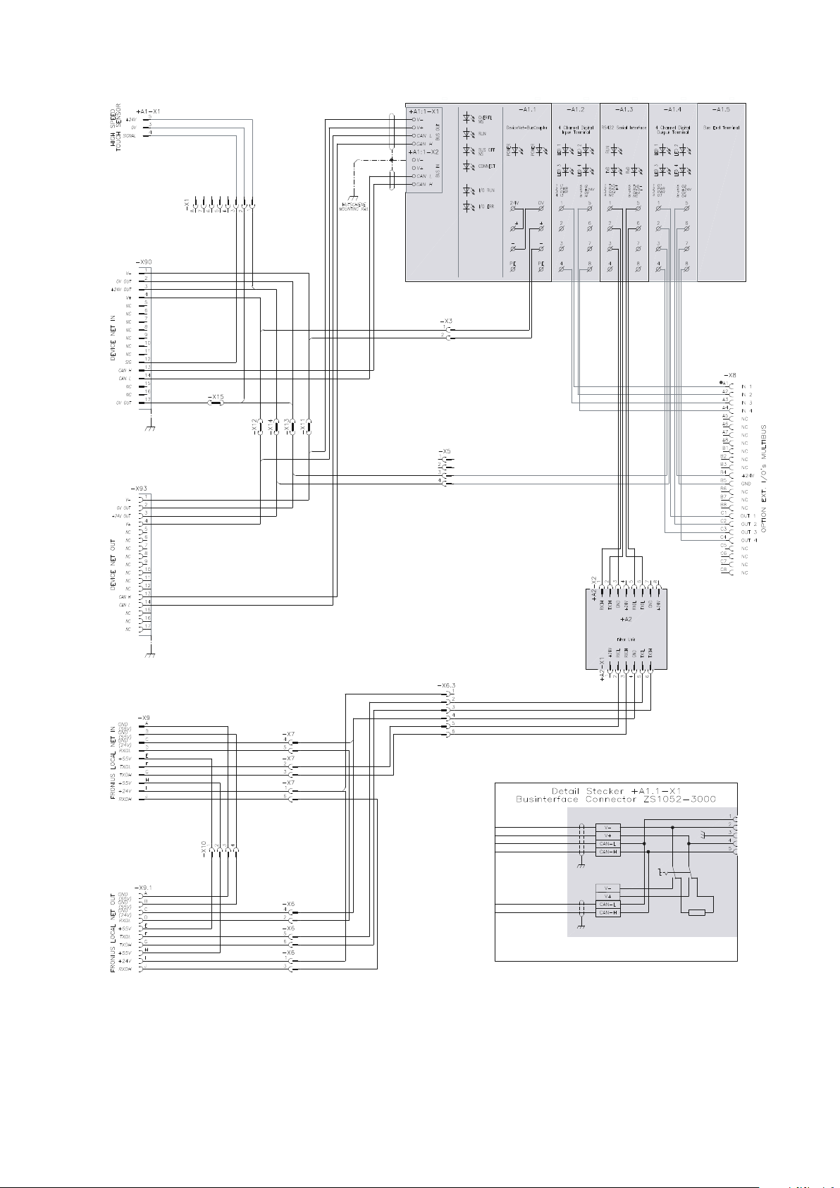
Schaltpläne
DeviceNet (4,100,252) - 1
DE
39
Page 40

DeviceNet (4,100,252) - 2
40
Page 41

Twin DeviceNet (4,100,400)
DE
41
Page 42
BK5200 KL1114 KL6021 KL2134 KL9010
BFU1A
DeviceNet Multibus (4,100,444)
42
Page 43

Contents
General 44
Safety 44
Basics 44
Machine concept 44
Interface connections - TS/TPS, MW/TT range 45
For your information 45
Application example - TS/TPS, MW/TT range 45
Instructions for installing the external version of the interface 46
Connecting and configuring the field bus coupler 47
Safety 47
Connections on the field bus coupler 47
Connecting the field bus coupler 47
Slave address configuration BK5250 49
Baud rate configuration BK5200 50
Data transmission properties 51
Transmission technology 51
Safety feature 51
Troubleshooting 52
Safety 52
General remarks 52
K bus / operating status LEDs (local errors) 53
Field bus status LEDs 54
DeviceNet/DeviceNet Twin signal description 55
General 55
Power source modes - TS/TPS, MW/TT series 55
Overview 55
Input and output signals for MIG/MAG - TS/TPS, MW/TT range 56
Input signals (from robot to power source) 56
Output signals (from power source to robot) 57
Input and output signals for TIG - TS/TPS, MW/TT range 59
Input signals (from robot to power source) 59
TIG pulsing range settings 60
Output signals (from power source to robot) 60
Input and output signals for CC/CV - TS/TPS, MW/TT range 62
Input signals (from robot to power source) 62
Output signals (from power source to robot) 63
Input and output signals for standard manual - TS/TPS, MW/TT range 65
Input signals (from robot to power source) 65
Output signals (from power source to robot) 66
Input and output signals for MIG/MAG Twin Device-Net (4.100.400) - TS/TPS, MW/TT range 68
Input signals (from robot to power source input) 68
Output signals (from power source to robot) 69
Input and output signals for MIG/MAG Twin DeviceNet John Deere (4.100.400.800) - TS/
TPS, MW/TT range
Input signals (from robot to power source) 71
Output signals (from power source to robot) 72
Configuration examples 74
General remarks 74
Configuration examples 74
Technical data 77
DeviceNet coupler BK5250 77
DeviceNet coupler BK5200 78
Circuit diagrams 79
EN
71
43
Page 44

General
Safety
Danger from incorrect operation and work that is not carried out properly.
This can result in serious personal injury and damage to property.
▶
▶
▶
Basics DeviceNet is an open, CAN-based system. CAN was developed several years ago
by the company R. Bosch for data transmission in motor vehicles. There are now
millions of CAN chips in use. A disadvantage of using CAN in automation applications is that it contains no definitions for the application layer. CAN only defines
the physical and data protection layer.
DeviceNet employs a standard application layer that makes the CAN protocol
useful for industrial applications. As an independent association, the ODVA
(Open DeviceNet Vendor Association) supports manufacturers and users of the
DeviceNet system. ODVA ensures that all devices that meet the specification
work together in one system, whether or not each device is manufactured by the
same company.
WARNING!
All the work and functions described in this document must only be carried
out by technically trained and qualified personnel.
Read and understand this document in full.
Read and understand all safety rules and user documentation for this device
and all system components.
By means of the bit arbitration process, CAN basically offers the option of operating communications networks using master/slave and multimaster access procedures. The bus coupler BK5200 (software version B2) supports master/slave operation (polling mode), where the bus coupler functions as slave. In future versions, the bus coupler will also support multimaster operation.
Machine concept The DeviceNet is characterised by its small footprint and high degree of modula-
rity. The fact that it can simply be fitted to a standardised C-rail (thus saving
space) and employs direct cabling of actuators and sensors without any interconnections between the terminals makes installation very straightforward. The uniform labelling concept further simplifies the installation.
44
Page 45
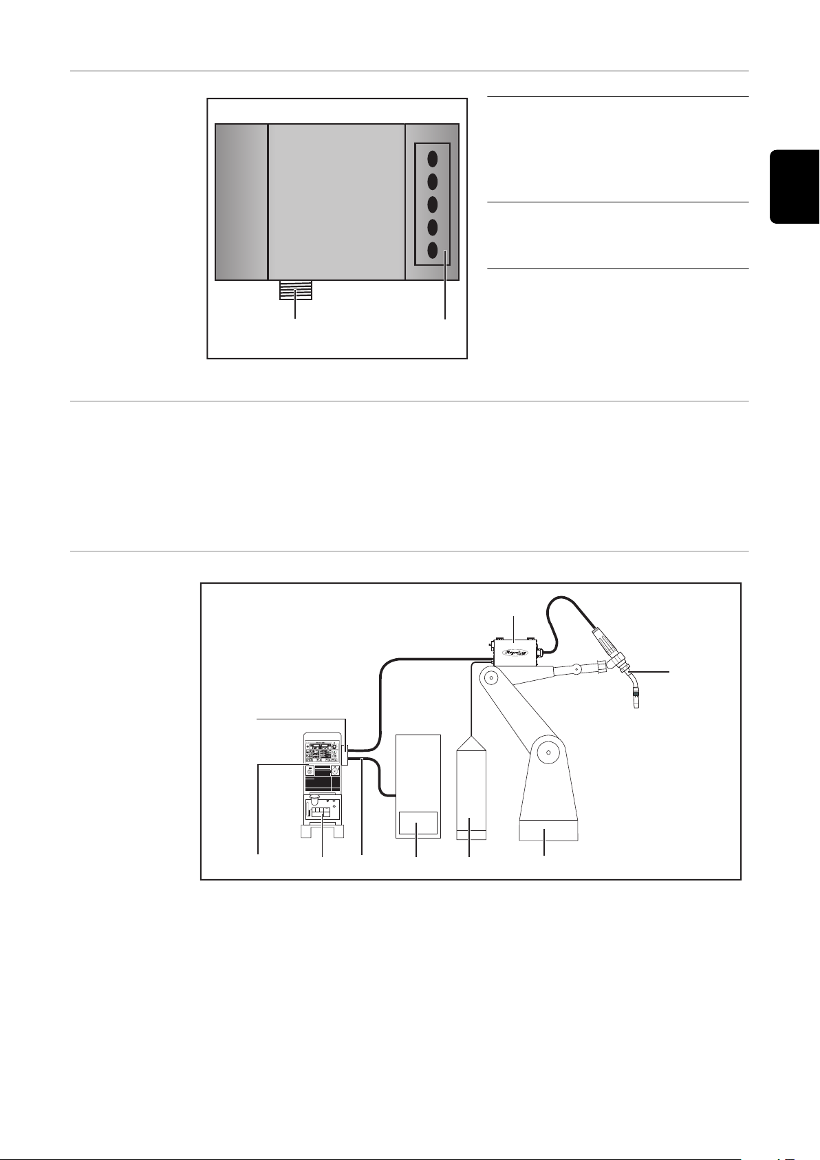
Interface con-
(2)
(1)
(1) (10)
(2)
(3)
(9)
(8) (7)
(6)
(5)
(4)
nections - TS/
TPS, MW/TT range
Interface connections
(1) Strain-relief device with cable
glands
for the DeviceNet data line and
the power supply for the field
bus coupler
(2) LocalNet connection
for connecting the interconnecting hosepack
EN
For your information
Application example - TS/TPS,
MW/TT range
IMPORTANT! While the robot interface is connected to the LocalNet, „2-step
mode“ remains selected (display: 2-step mode).
Further information on the „special 2-step mode for robot interface“ can be
found in the sections headed „MIG/MAG welding“ and „Mode welding parameters“ in the power source operating instructions.
(1) Power source
(2) DeviceNet
(3) Interconnecting hosepack
(4) Wire-feed unit
(5) Welding torch
(6) Robot
(7) Welding wire drum
(8) Robot control
(9) DeviceNet data cable
(10) Cooling unit
45
Page 46

Instructions for
installing the external version of
the interface
IMPORTANT! The following guidelines must be followed when installing the ex-
ternal version of the interface:
The cables must be routed separately from mains leads
-
The field bus coupler must be installed separately from the mains leads or
-
components
The field bus coupler may only be installed somewhere that provides protec-
-
tion from dirt and water
Make sure that the 24 V supply voltage is safely isolated from higher-voltage
-
circuits.
46
Page 47
Connecting and configuring the field bus coupler
(1)
(2)
(3)
BK5200
BECKHOFF
(1)
(2)
(3)
Safety
Connections on
the field bus
coupler
WARNING!
Danger from electrical current.
This can result in serious personal injury and damage to property.
Before starting work, switch off all devices and components involved and dis-
▶
connect them from the grid.
Secure all devices and components involved so they cannot be switched back
▶
on.
After opening the device, use a suitable measuring instrument to check that
▶
electrically charged components (such as capacitors) have been discharged.
EN
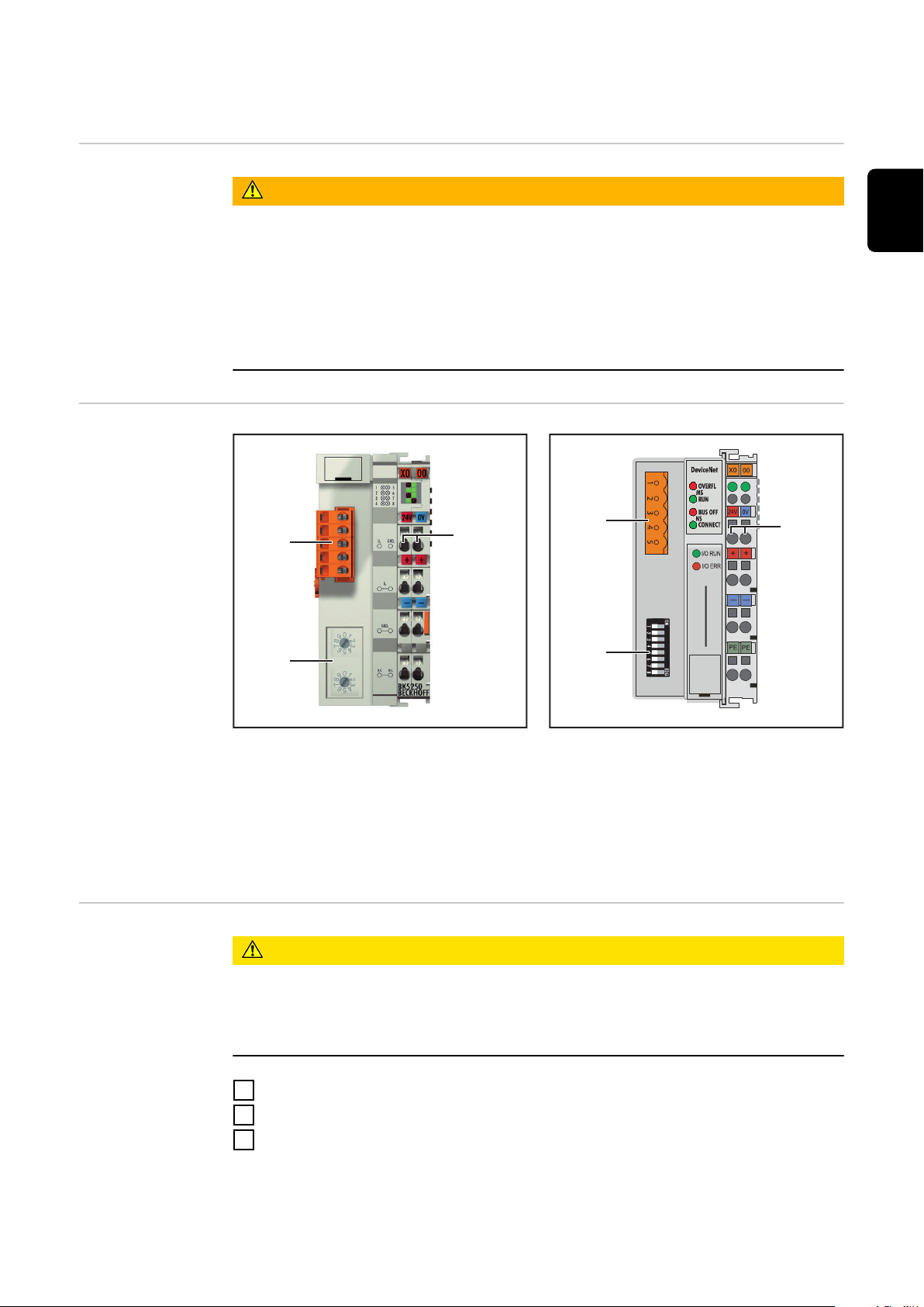
Connecting the
field bus coupler
Elements on the field bus coupler BK5250
(1) DeviceNet connection
(2) Address selector / Baud rate setting
(3) Connections for external power supply
IMPORTANT! External power supply must not come via the power source. Use
the robot or control for the external power supply..
CAUTION!
Danger from electrical current.
This can result in severe damage to property.
Before starting work, ensure that the cables for the external power supply to
▶
the interface are and remain de-energised until all work is complete.
Remove the interface lid
1
Remove the strain-relief device from the interface
2
Feed the DeviceNet data line and cable for the external power supply
3
through the cable gland in the strain-relief device
Elements on the field bus coupler BK5200
47
Page 48

The bus cable consists of one 2x2 core twisted-pair and screened line. Of the two
V+
CAN_H
SHIELD
CAN_L
CAN_V-
Red P.M.S. #207C
White EIA 395 A within wire/cable limits
Blue P.M.S. #297C
Black P.M.S. #426C
pairs of wires, one is responsible for
data transfer
-
and one for the power supply (currents up to 8 A possible, depending on the
-
cable)
IMPORTANT! Maximum permitted cable length depends on the Baud rate. Depending on the Baud rate chosen, cable lengths can be:
max. 100 m at the highest Baud rate (500 kBaud)
-
max. 500 m at the lowest Baud rate (125 kBaud)
-
The DeviceNet bus cable is connected using the 5-pin plug provided. Pin 1 is located on the top of the bus coupler.
Connect the data lines to pin 2 and pin 4 as shown in the illustration below
4
(observe polarity)
NOTE! In order to avoid reflections and any transmission problems, fit resis-
tors to both ends of the field bus cable.
Connect power supply to pin 1 and pin 5 (observe polarity)
5
Connect
6
- pin 1 to terminal X1/24 V
- pin 5 to terminal X1/0 V
IMPORTANT! Both voltages must be connected before the field bus coupler can
be used.
DeviceNet connection with pin assignments
BK5200 BK5250
Vendor ID 108 108
Device Type 12 12
48
Produkt Code 5200 5250
DeviceNet Group Group 2 Group 2
MajRev 3 1
MinRev 0 1
ProdName - BK5250 V01.01
Page 49

Make the electrical connection between the „insulated DIN rail“ (1) and the
(1)
(2)
7
bus cable shield (2).
IMPORTANT! Use only „insulated“ DIN rails when fitting the field bus coupler. Ensure that the DIN rail has no electrical contact with the earth of the
power source.
EN
Slave address
configuration
BK5250
Connecting the DIN rail to the bus cable shield - TS/TPS, MW/TT series
Check that the shield is connected to the robot earth
8
Connect the external power supply from the robot or control system to the
9
connections for the external power supply on the field bus coupler
Attach the DeviceNet data line and cable for the external power supply to
10
the cable gland in the strain-relief device using cable ties
Attach the strain-relief device to the interface using the original fixings. En-
11
sure that the strain-relief device assumes its original position
For the TS/TPS, MW/TT series:
Connect the LocalNet plug on the interconnecting hosepack to the LocalNet
12
connection on the interface
Set slave address using the two rotary selector switches.
Default setting = 11
All addresses are permitted, each address may only appear once on the network.
Ensure that all devices and components have been switched off and discon-
1
nected from the mains
Ensure that the interface has been disconnected from the mains
2
Move switch to desired position using a screwdriver
3
Values on the upper switch represent units
-
Values on the lower switch represent tens
-
IMPORTANT! Ensure that the switches engage properly
49
Page 50

0
1
2
3
4
5
6
7
8
9
0
1
2
3
4
5
6
7
8
9
x 1
x 10
Example
Setting address 34:
Upper rotary selector switch S520:
-
4
Lower rotary selector switch S521:
-
3
Using the original screws, fit the interface lid back into its original position
4
Baud rate configuration BK5200
IMPORTANT! Set the bus coupler node number and Baud rate before starting up
the bus coupler.
Ensure that all devices and components have been switched off and discon-
1
nected from the mains
Ensure that the interface has been disconnected from the mains
2
Set MAC ID using DIP switches 1 to 6:
3
-
Switch 1 = least significant bit (20)
-
Switch 6 = most significant bit (25)
The bit is set if the switch is in the ON
position
The MAC ID can be in the range 0 to
63.
The Baud rate is set using switches 7 and 8. The following table contains information about the different Baud rate settings.
Baud rate setting 1 2 3 4 5 6 7 8
125 kBd - - - - - - off off
250 kBd - - - - - - on off
500 kBd - - - - - - off on
(Default) 125 kBd - - - - - - on on
Using the original screws, fit the interface lid back into its original position
4
50
Page 51

Data transmission properties
Transmission
technology
Network topology
Linear bus, bus termination at both ends (121 Ohm), spur lines are possible
Medium
Screened 2x2 core twisted-pair cable, must be screened.
Number of stations
max. 64 nodes
Max. bus length
depends on the Baud rate:
100 m at 500 kBit/s, 250 m at 250 kBit/s, 500 m at 125 kBit/s
Transmission speed
500 kBit/s, 250 kBit/s, 125 kBit/s
Connector
Open Style connector, 5-pin
Operating modes
Bit strobe, polling, cyclic, „Change of State“ (COS)
Process data width
96 bits (Standard configuration)
Process data format
Intel
EN
Safety feature The field bus nodes are equipped with a shutdown monitor so the power source
can interrupt the process if data transmission drops out. If there is no data transmission within 700ms, all inputs and outputs are reset and the power source
goes into „Stop“. Once data transmission has been re-established, the following
signals resume the process:
“Robot ready” signal
-
“Source error reset” signal
-
51
Page 52

Troubleshooting
(5)
(6)
(7)
(8)
(1)
(2)
(3)
(4)
BK5200
BECKHOFF
(10)
(11)
(9)
Safety
General remarks
WARNING!
Danger from electrical current.
This can result in serious personal injury and damage to property.
Before starting work, switch off all devices and components involved and dis-
▶
connect them from the grid.
Secure all devices and components involved so they cannot be switched back
▶
on.
After opening the device, use a suitable measuring instrument to check that
▶
electrically charged components (such as capacitors) have been discharged.
(1) LED ADR (Module)
(2) LED RUN (Module)
(3) LED TX overflow (Net)
(4) LED overflow (Net)
(5) LED bus coupler supply
(6) LED power contacts supply
(7) LED K bus RUN
(8) LED K bus ERR
Elements on the field bus coupler BK5250
(9) Operating status LEDs
(10) Field bus status LEDs
(11) Supply LEDs
left-hand LED ... monitors
-
the field bus coupler power
supply
right-hand LED... monitors
-
the power contact supply
Elements on the field bus coupler BK5200
If an error occurs, the field bus status/operating status LEDs signal the type of
error and where it occurred.
52
WICHTIG! In some cases, the field bus coupler does not complete the flashing
sequence once the error has been rectified. Restart the field bus coupler by switching the supply voltage off and on again, or by resetting the software.
Page 53

K bus / operating
(a) (b) (c)
status LEDs (local errors)
The K bus LEDs (operating status LEDs) monitor local communications between
the field bus coupler and field bus terminals. The green LED lights when there
are no errors. The red LED flashes at two different intervals if a terminal bus error occurs.
Rapid flashing:
a)
Start of the error code
First slow pulse:
b)
Type of error
Second slow pulse:
c)
Error location
IMPORTANT! The number of pulses
indicates the location of the last field
bus terminal prior to where the error
occurred. Passive field bus terminals
(e.g. supply terminals) are not counted.
Flash code
Error code Error argument Description
1 pulse 0 EEPROM check sum error
EN
1 Inline code buffer overflow
2 Unknown data type
2 pulses
0
Programmed configuration
Incorrect table entry/bus coupler
n (n<0) Terminal(s) table comparison incorrect
3 pulses 0 Terminal bus command error
4 pulses 0 Terminal bus data error
n (n<0) Break behind terminal(s) (0:coupler)
5 pulses n (n<0) Terminal bus error during register commu-
nication with terminal(s)
6 pulses 0 Special field bus error
n (n<0)
IMPORTANT! When an error occurs during operation, the error code is not
immediately indicated on the LEDs. The bus coupler must be requested to perform a diagnosis of the bus terminals. The diagnosis request is generated after
switching on, or is requested by the master.
53
Page 54

Field bus status
LEDs
The field bus status LEDs indicate the operating status of the field bus.
Module Status
LED „MS RUN“, green LED
- flashes
- is steady
LED „MS OVERFL“, red LED
- flashes
- is steady
Network Status
LED „NS CONNECT“, green LED
- flashes Bus coupler ready to communicate, but
LED „NS BUS OFF“, green LED
- is steady Bus coupler is assigned to the master,
LED „NS BUS OFF“, red LED
- flashes
- is steady
Configuration incorrect
Status OK
Receive queue overflow
Status OK
not yet assigned to the master
data exchange taking place
I/O connection timeout
BUS OFF: CAN error, node with identical node address
54
Page 55

DeviceNet/DeviceNet Twin signal description
BK 5200
BK 5250
KL6021-0010
KL9010
General The following signal descriptions apply to an interface with a KL 6021-0010 com-
munication terminal (standard version)
Extra terminals can also be installed in a robot interface. However, the number
that can be installed is limited by the size of the housing.
IMPORTANT! When installing extra terminals, the process data image changes.
EN
Power source
modes - TS/TPS,
MW/TT series
Overview ‘DeviceNet/DeviceNet Twin’ signal description is composed of the following sec-
Depending on the selected mode, the DeviceNet/DeviceNet Twin interface can
transfer a wide variety of input and output signals.
Mode E05 E04 E03
MIG/MAG standard synergic welding 0 0 0
MIG/MAG pulsed arc welding 0 0 1
Job mode 0 1 0
Internal parameter selection 0 1 1
TIG 1 1 0
CC/CV 1 0 1
Standard manual welding 1 0 0
CMT/special process 1 1 1
tions:
Input and output signals for MIG/MAG - TS/TPS, MW/TT range
-
Input and output signals for TIG - TS/TPS, MW/TT range
-
Input and output signals for CC/CV - TS/TPS, MW/TT range
-
Input and output signals for standard manual - TS/TPS, MW/TT range
-
Input and output signals for MIG/MAG Twin DeviceNet - TS/TPS, MW/TT
-
range
Input and output signals for MIG/MAG Twin DeviceNet John Deere - TS/
-
TPS, MW/TT range
55
Page 56

Input and output signals for MIG/MAG - TS/TPS,
MW/TT range
Input signals
(from robot to
power source)
Seq. no. Signal designation Field Activity
E01 Welding start - High
E02 Robot ready - High
E03 Bit 0 operating modes - High
E04 Bit 1 operating modes - High
E05 Bit 2 operating modes - High
E06 Master selection Twin - High
E07 - E08 Not in use - -
E09 Gas test - High
E10 Wire inching - High
E11 Wire retract - High
E12 Source error reset - High
E13 Touch sensing - High
E14 Torch blow through - High
E15 - E 16 Not in use - -
E17 - E24 Job number 0 - 99 -
E25 - E31 Program number 0 - 127 -
E32 Welding simulation - High
With RCU 5000i remote control unit and in Job mode
E17 - E23 Job number 0 - 999 -
E32 Welding simulation - High
Power (command value) 0 - 65535
(0 % - 100 %)
E33 - E40 Low byte - -
E41 - E48 High byte - -
Arc length correction (com-
mand value)
E49 - E56 Low byte - -
E57 - E64 High byte - -
0 - 65535
(-30 % - +30 %)
-
-
56
E65 - E72 Pulse/dynamic correction (com-
mand value)
0 - 255
(-5 % - +5 %)
-
Page 57

Seq. no. Signal designation Field Activity
Output signals
(from power
source to robot)
E73 - E80 Burn-back (command value) 0 - 255
(-200 ms - +200
ms)
E81 Synchro Puls disable - High
E82 SFI disable - High
E83 Pulse/dynamic correction dis-
able
E84 Burn-back disable - High
E85 Full power range (0 - 30 m) - High
E86 Not in use - -
E87 - E96 Welding speed 0 - 1023
Seq. no. Signal designation Field Activity
A01 Arc stable - High
A02 Limit signal (only with RCU
5000i)
- High
(0 - 1023 cm/min)
- High
-
-
EN
A03 Process active - High
A04 Main current signal - High
A05 Torch collision protection - High
A06 Power source ready - High
A07 Communication ready - High
A08 Spare - -
A09 - A16 Error number 0 - 255 -
A17 - A24 Not in use - -
A25 Wire stick control
(wire released from weldpool)
A26 Not in use - -
A27 Robot access (only with RCU
5000i)
A28 Wire available - High
A29 Timeout short circuit - High
A30 Data documentation ready - High
A31 Not in use - -
- High
- High
A32 Power outside range - -
Welding voltage (real value) 0 - 65535
(0 - 100 V)
A33 - A40 Low byte - -
A41 - A48 High byte - -
-
57
Page 58

Seq. no. Signal designation Field Activity
Welding current (real value) 0 - 65535
(0 - 1000 A)
A49 - A56 Low byte - -
A57 - A64 High byte - -
A65 - A72 Motor current (real value) 0 - 255
(0 - 5 A)
A73 - A80 Not in use - -
Wire feed speed (actual value) 0 - 65535
(-327.68 - +327.67
m/min)
A81 - A88 Low byte - -
A89 - A96 High byte - -
-
-
58
Page 59

Input and output signals for TIG - TS/TPS,
MW/TT range
Input signals
(from robot to
power source)
Seq. no. Signal designation Field Activity
E01 Welding start - High
E02 Robot ready - High
E03 Bit 0 modes - High
E04 Bit 1 modes - High
E05 Bit 2 modes - High
E06 Master selection twin - -
E07 - E08 Not in use - -
E09 Gas test - High
E10 Wire inching - High
E11 Wire retract - High
E12 Source error reset - High
E13 Touch sensing - High
E14 Cold wire disable - High
E15 - E16 Not in use - -
E17 - E24 Job number 0 - 99 -
EN
E25 DC / AC - High
E26 DC- / DC+ - High
E27 Cap shaping - High
E28 Pulse disable - High
E29 Pulse range bit 0 - High
E30 Pulse range bit 1 - High
E31 Pulse range bit 2 - High
E32 Welding simulation - High
Main current (command value) 0 - 65535
(0 bis I
E33 - E40 Low byte - -
E41 - E48 High byte - -
External parameter (command
value)
E49 - E56 Low byte - -
E57 - E64 High byte - -
0 - 65535 -
max
)
-
E65 - E72 Base current (command value) 0 - 255
(0% - 100%)
-
59
Page 60

Seq. no. Signal designation Field Activity
TIG pulsing range settings
E73 - E80 Duty cycle (command value) 0 - 255
-
(10% - 90%)
E81 - E82 Not in use - -
E83 Base current disable - High
E84 Duty cycle disable - High
E85 - E86 Not in use - -
E87 - E96 Wire speed Wfi (command va-
lue)
0 - 1023
(0 - vD
max
-
)
Operating mode E31 E30 E29
Set pulsing range on the power source 0 0 0
Pulse setting range deactivated 0 0 1
0.2 - 2 Hz 0 1 0
2 - 20 Hz 0 1 1
20 - 200 Hz 1 0 0
Output signals
(from power
source to robot)
200 - 2000 Hz 1 0 1
Seq. no. Signal designation Field Activity
A01 Arc stable - High
A02 Not in use - -
A03 Process active - High
A04 Main current signal - High
A05 Torch collision protection - High
A06 Power source ready - High
A07 Communication ready - High
A08 Spare - -
A09 - A16 Error number 0 - 255
A17 - A25 Not in use - -
A26 High frequency active - High
A27 Not in use - -
60
A28 Wire available - High
A29 - A30 Not in use - -
A31 Pulse high - High
A32 Not in use - -
Page 61

Seq. no. Signal designation Field Activity
Welding voltage (real value)
A33 - A40 Low byte - -
A41 - A48 High byte - -
Welding current (actual value) 0 - 65535
A49 - A56 Low byte - -
A57 - A64 High byte - -
A65 - A72 Motor current (actual value) 0 - 255
A73 - A80 Arc length (actual value) (AVC) 0 - 255 -
Wire feed speed (actual value) 0 - 65535
A81 - A88 Low byte - -
0 - 65535
(0 - 100 V)
(0 - 1000 A)
(0 - 5 A)
(-327.68 - +327.67
m/min)
-
EN
-
-
-
A89 - A96 High byte - -
61
Page 62

Input and output signals for CC/CV - TS/TPS,
MW/TT range
Input signals
(from robot to
power source)
Seq. no. Signal designation Field Activity
E01 Welding start - High
E02 Robot ready - High
E03 Bit 0 operating modes - High
E04 Bit 1 operating modes - High
E05 Bit 2 operating modes - High
E06 Master selection twin - High
E07 - E08 Not in use - -
E09 Gas test - High
E10 Wire inching - High
E11 Wire retract - High
E12 Source error reset - High
E13 Touch sensing - High
E14 Torch blow through - High
E15 - E16 Not in use - -
E17 - E24 Job number 0 - 99 -
E25 - E31 Program number 0 - 127 -
E32 Welding simulation - High
With RCU 5000i remote control unit and in Job mode
E17 - E31 Job number 0 - 999
E32 Welding simulation - High
Welding current (command va-
lue)
E33 - E40 Low byte - -
E41 - E48 High byte - -
Wire speed (command value) 0 - 65535
E49 - E56 Low byte - -
E57 - E64 High byte - -
0 - 65535
(0 - I
max
(0,5 - vD
)
max
-
-
)
62
E65 - E72 Welding voltage (command va-
lue)
E73 - E80 Not in use - -
0 - 255
(0 - 50 V)
-
Page 63

Seq. no. Signal designation Field Activity
E81 Synchro Puls disable - High
E82 SFI disable - High
E83 Welding voltage disable - High
Output signals
(from power
source to robot)
E84 Not in use - -
E85 Full power range (0 - 30 m) - High
E86 Not in use - -
E87 - E96 Welding speed 0 - 1023
(0 - 1023 cm/min)
Seq. no. Signal designation Field Activity
A01 Arc stable - High
A02 Limit signal (only with RCU
5000i)
A03 Process active - High
A04 Main current signal - High
A05 Torch collision protection - High
A06 Power source ready - High
A07 Communication ready - High
A08 Spare - -
- High
-
EN
A09 - A16 Error number 0 - 255 -
A17 - A24 Not in use - -
A25 Wire stick control
(wire released from weldpool)
A26 Not in use - -
A27 Robot access (only with RCU
5000i)
A28 Wire available - High
A29 Timeout short circuit - High
A30 Data documentation ready - High
A31 Not in use - -
A32 Power outside range - -
Welding voltage (real value) 0 - 65535
A33 - A40 Low byte - -
A41 - A48 High byte - -
- High
- High
-
(0 - 100 V)
Welding current (real value) 0 - 65535
(0 - 1000 A)
-
63
Page 64

Seq. no. Signal designation Field Activity
A49 - A56 Low byte - -
A57 - A64 High byte - -
A65 - A72 Motor current (real value) 0 - 255
(0 - 5 A)
A73 - A80 Not in use - -
Wire feed speed (actual value) (-327.68 - +327.67
m/min)
A81 - A88 Low byte - -
A89 - A96 High byte - -
-
-
64
Page 65

Input and output signals for standard manual TS/TPS, MW/TT range
Input signals
(from robot to
power source)
Seq. no. Signal designation Field Activity
E01 Welding start - High
E02 Robot ready - High
E03 Bit 0 operating modes - High
E04 Bit 1 operating modes - High
E05 Bit 2 operating modes - High
E06 Master selection twin - High
E07 - E08 Not in use - -
E09 Gas test - High
E10 Wire inching - High
E11 Wire retract - High
E12 Source error reset - High
E13 Touch sensing - High
E14 Torch blow through - High
E15 - E16 Not in use - -
E17 - E24 Job number 0 - 99 -
EN
E25 - E31 Program number 0 - 127 -
E32 Welding simulation - High
With RCU 5000i remote control unit and in Job mode
E17 - E31 Job number 0 - 999 -
E32 Welding simulation - High
Wire speed (command value) 0 - 65535
(0.5 - vD
E33 - E40 Low byte - -
E41 - E48 High byte - -
Welding voltage (command va-
lue)
E49 - E56 Low byte - -
E57 - E64 High byte - -
0 - 65535
(10 - 40 V)
max
)
-
-
E65 - E72 Dynamic correction (command
value)
0 - 255
(0 - 10)
-
65
Page 66

Seq. no. Signal designation Field Activity
Output signals
(from power
source to robot)
E73 - E80 Burn-back (command value) 0 - 255
(-200 ms - +200
ms)
E81 Synchro Puls disable - High
E82 SFI disable - High
E83 Dynamic correction disable - High
E84 Burn-back disable - High
E85 Full power range (0 - 30 m) - High
E86 Not in use - -
E87 - E96 Welding speed 0 - 1023
(0 - 1023 cm/min)
Seq. no. Signal designation Field Activity
A01 Arc stable - High
A02 Limit signal (only with RCU
5000i)
- High
-
-
A03 Process active - High
A04 Main current signal - High
A05 Torch collision protection - High
A06 Power source ready - High
A07 Communication ready - High
A08 Spare - -
A09 - A16 Error number 0 - 255 -
A17 - A24 Not in use - -
A25 Wire stick control
(wire released from weldpool)
A26 Not in use - -
A27 Robot access (only with RCU
5000i)
A28 Wire available - High
A29 Timeout short circuit - High
A30 Data documentation ready - High
A31 Not in use - -
- High
- High
66
A32 Power outside range - High
Welding voltage (real value) 0 - 65535
(0 - 100 V)
A33 - A40 Low byte - -
A41 - A48 High byte - -
-
Page 67

Seq. no. Signal designation Field Activity
Welding current (real value) 0 - 65535
(0 - 1000 A)
A49 - A56 Low byte - -
A57 - A64 High byte - -
A765- A72 Motor current (real value) 0 - 255
(0 - 5 A)
A73 - A80 Not in use - -
Wire feed speed (actual value) 0 - 65535 -
(-327.68 - +327.67
m/min)
A81 - A88 Low byte - -
A89 - A96 High byte - -
-
EN
-
-
67
Page 68

Input and output signals for MIG/MAG Twin Device-Net (4.100.400) - TS/TPS, MW/TT range
Input signals
(from robot to
power source input)
Seq. no. Signal designation Field Activity
E01 Welding start - High
E02 Robot ready - High
E03 Bit 0 modes - High
E04 Bit 1 modes - High
E05 Bit 2 modes - High
E06 Master selection twin
Power source 1
E07 Master selection twin
Power source 2
E08 Not in use - -
E09 Gas test - High
E10 Wire inching - High
E11 Wire retract - High
E12 Source error reset - High
E13 Touch sensing - High
E14 Torch blow out - High
- High
- High
E15 - E16 Not in use - -
E17 - E24 Job number 0 - 99 -
E25 - E31 Program number 0 - 127 -
E32 Welding simulation - High
With RCU 5000i and in Job mode
E17 - E31 Job number 0 - 999 -
E32 Welding simulation - High
E33 - E48 Power (command value)
power source 1
E49 - E64 Arc length correction (com-
mand value)
power source 1
E65 - E72 Pulse/dynamic correction (com-
mand value)
power source 1
E73 - E80 Burn-back (command value)
power source 1
0 - 65535
(0 - 100 %)
0 - 65535
(-30 % - +30 %)
0 - 255
(-5 % - +5 %)
0 - 255
(-200 - +200 ms)
-
-
-
-
68
E81 - E96 Not in use - -
E97 - E112 Power (command value)
power source 2
0 - 65535
(0 - 100 %)
-
Page 69

Seq. no. Signal designation Field Activity
Output signals
(from power
source to robot)
E113 - 128 Arc length correction (com-
mand value)
power source 2
E129 - 136 Pulse/dynamic correction (com-
mand value)
power source 2
E137 - 144 Burn-back (command value)
power source 2
E145 - 152 Not in use - -
E153 - 160 Standard I/O KL2134 - -
Seq. no. Signal designation Field Activity
A01 Arc stable - High
A02 Limit signal (only with RCU
5000i)
A03 Process active - High
A04 Main current signal - High
0 - 65535
(-30 % - +30 %)
0 - 255
(-5 % - +5 %)
0 - 255
(-200 - +200 ms)
- High
-
-
-
EN
A05 Torch collision protection - High
A06 Power source ready - High
A07 Communication ready - High
A08 Spare - -
A09 - A16 Error number power source 1 0 - 255 -
A17 - A24 Error number power source 2 0 - 255 -
A25 Wire stick control (wire released
from weldpool)
A26 Not in use - -
A27 Robot access (only with RCU
5000i)
A28 Wire available - High
A29 - A32 Not in use - -
A33 - A48 Welding voltage (real value) 0 - 65535 -
A49 - A64 Welding current (real value)
power source 1
A65 - A72 Motor current (real value)
power source 1
High
High
0 - 65535
(0 - 1000 A)
0 - 255
(0 - 5 A)
-
-
A73 - A80 Not in use - -
A81 - A96 Wire speed (real value)
power source 1
A97 - 112 Welding voltage (real value)
power source 2
0 - 65535
(-327.68 - +327.67
m/min)
0 - 65535
(0 - 100 V)
-
-
69
Page 70

Seq. no. Signal designation Field Activity
A113 - 128 Welding current (real value)
power source 2
A129 - 136 Motor current (real value)
power source 2
A137 - 144 Not in use - -
A145 - 160 Wire speed (real value)
power source 2
A161 - 168 Not in use - -
A169 - 172 Standard I/O KL1114 - -
0 - 65535
(0 - 1000 A)
0 - 255
(0 - 5 A)
0 - 65535
(-327.68 - +327.67
m/min)
-
-
-
70
Page 71

Input and output signals for MIG/MAG Twin DeviceNet John Deere (4.100.400.800) - TS/TPS,
MW/TT range
EN
Input signals
(from robot to
power source)
Seq. no. Signal designation Field Activity
E01 Welding start - High
E02 Robot ready - High
E03 Bit 0 modes - High
E04 Bit 1 modes - High
E05 Bit 2 modes - High
E06 Master selection twin power
source 1
E07 Master selection twin power
source 2
E08 Not in use - -
E09 Gas test - High
E10 Wire inching - High
E11 Wire retract - High
E12 Source error reset - High
E13 Touch sensing - High
E14 Torch blow out - High
- High
- High
E15 - E16 Not in use - -
E17 - E24 Job number power source 1 0 - 99 -
E25 - E31 Program number 0 - 127 -
E32 Welding simulation - High
With RCU 5000i and in Job mode
E17 - E31 Job number 0 - 999 -
E32 Welding simulation - High
E33 - E48 Power (command value)
power source 1
E49 - E64 Arc length correction (com-
mand value)
power source 1
E65 - E72 Pulse/dynamic correction (com-
mand value)
power source 1
E73 - E80 Burn-back (command value)
power source 1
0 - 65535
(0 - 100 %)
0 - 65535
(-30 % - +30 %)
0 - 255
(-5 % - +5 %)
0 - 255
(-200 - +200 ms)
-
-
-
-
E81 - E96 Power (command value)
power source 2
0 - 65535
(0 - 100 %)
-
71
Page 72

Seq. no. Signal designation Field Activity
Output signals
(from power
source to robot)
E97 - 112 Arc length correction (com-
mand value)
power source 2
E113 - 120 Pulse/dynamic correction (com-
mand value)
power source 2
E121 - 128 Burn-back (command value)
power source 2
E129 - 136 Standard I/O KL2134 - -
E137 - 144 Job number power source 2 0 - 99 -
Seq. no. Signal designation Field Activity
A01 Arc stable - High
A02 Limit signal (only with RCU
5000i)
A03 Process active - High
A04 Main current signal - High
0 - 65535
(-30 % - +30 %)
0 - 255
(-5 % - +5 %)
0 - 255
(-200 - +200 ms)
- High
-
-
-
A05 Torch collision protection - High
A06 Power source ready - High
A07 Communication ready - High
A08 Spare - -
A09 - A16 Error number power source 1 0 - 255 -
A17 - A24 Error number power source 2 0 - 255 -
A25 Wire stick control (wire released
from weldpool)
A26 Not in use - -
A27 Robot access (with RCU 5000i) High
A28 Wire available - High
A29 - A32 Not in use - -
A33 - A48 Welding voltage (real value)
power source 1
A49 - A64 Welding current (real value)
power source 1
A65 - A72 Motor current (real value)
power source 1
High
0 - 65535
(0 - 100 V)
0 - 65535
(0 - 1000 A)
0 - 255
(0 - 5 A)
-
-
-
72
A73 - A80 Not in use - -
A81 - A96 Wire speed (real value) power
source 1
A97 - A112 Welding voltage (real value)
power source 2
0 - 65535
(-327,68 - +327,67
m/min)
0 - 65535
(0 - 100 V)
-
-
Page 73

Seq. no. Signal designation Field Activity
A113 - 128 Welding current (real value)
power source 2
A129 - 136 Motor current (real value)
power source 2
A137 - 144 Not in use - -
A145 - 160 Wire speed (real value)
power source 2
A161 - 168 Not in use - -
A169 - 172 Standard I/O KL1114 - -
0 - 65535
(0 - 1000 A)
0 - 255
(0 - 5 A)
0 - 65535
(-327,68 - +327,67
m/min)
-
-
EN
-
73
Page 74

Configuration examples
BK 5200
KL6021-0010
KL9010
KL6021-0015
General remarks Terminals can be either bit-oriented (digital) or byte-oriented (analog/complex).
digital terminals: KL1114, KL2134, KL2612
-
analog terminals: KL4001
-
complex terminals: KL 6021
-
The process image first shows the byte-oriented terminals, with the bit-oriented
terminals behind. With terminals of the same type, their position is also significant. Due to the different ways of installing the terminals, it is not possible to
show a generally applicable process image. Therefore, each installation set is described in signal order, with E97/A97 at the beginning.
IMPORTANT! The correct process image can only be determined using the terminals that are actually plugged in.
Configuration
examples
Arrangement of signals when using the component number installation set
(4,100,458)
Input Remarks Range Activity
Power source
E97 - E104 Not in use - -
E105 - E112 Character 1 32 - 254 -
E113 - E120 Character 2 32 - 254 -
E121 - E128 Character 3 32 - 254 -
E129 - E136 Character 4 32 - 254 -
E137 - E144 Character 5 32 - 254 -
E145 - E152 Character 6 32 - 254 -
74
E153 - E160 Character 7 32 - 254 -
E161 - E168 Character 8 32 - 254 -
E169 - E176 Character 9 32 - 254 -
E177 - E184 Character 10 - -
E185 - E192 Character 11 32 - 254 -
Output Remarks Range Activity
Power source
A97 - A192 Not in use - -
Page 75

Signal assignments when using the external I/O field bus installation set
BK 5200
KL1114
KL2134
KL6021-0010
KL9010
BK 5200
KL9010
KL2612
KL6021
BK 5200
KL2134
KL6021
KL4001
KL4001
KL9010
(4,100,287)
Input Remarks Range Activity
Power source
E97 Digital out 1 - KL2134 / 1 - High
E98 Digital out 2 - KL2134 / 5 - High
E99 Digital out 3 - KL2134 / 4 - High
E100 Digital out 4 - KL2134 / 8 - High
Output Remarks Range Activity
Power source
A97 Digital in 1 - KL1114 / 1 - High
EN
A98 Digital in 2 - KL1114 / 5 - High
A99 Digital in 3 - KL1114 / 4 - High
A100 Digital in 4 - KL1114 / 8 - High
Signal assignments when using the twin-head field bus installation set
(4,100,395)
Input Remarks Range Activity
Power source
E97 Digital out 1 - KL2612 / 1 - High
E98 Digital out 2 - KL2612 / 5 - High
Signal assignments when using the external field bus installation set 2AO/4DO
(4,100,462)
75
Page 76

Input Remarks Range Activity
Power source
E97 – E112 Analog out 1 KL4001 / 1 0 – 32767
(0 - 10 V)
E113 – E128 Analog out 2 KL4001 / 1 0 – 32767
(0 - 10 V)
E129 Digital out 1 - KL2134 / 1 - High
E130 Digital out 2 - KL2134 / 5 - High
E131 Digital out 3 - KL2134 / 4 - High
E132 Digital out 4 - KL2134 / 8 - High
-
-
76
Page 77

Technical data
DeviceNet coupler BK5250
Power supply 24 V DC (20 to 29 V DC)
via 11 - 25 V bus cable
(acc. to DeviceNet specification)
Current-input approx. 100 mA
Electrical isolation 500 V
(K bus / supply voltage)
Number of bus terminals 64
Peripheral bytes 512 input bytes
512 output bytes
Configuration interface available for KS2000
Baud rates Standard-compliant:
125 kBaud, 250 kBaud, 500 kBaud
Electrical strength 500 V
(power contact / supply voltage)
Operating temperature 0 °C to +55 °C
Storage temperature -25 °C to +85 °C
Relative humidity 95 % without condensation
Vibration/shock resistance as per IEC 68-2-6/IEC 68-2-27
eff
eff
EN
EMC resistance Burst / ESD as per EN 50082 (ESD, Burst) / EN50081
Installation position any
Protection IP20
VendCode 108
VendName Beckhoff Industrie Elektronik
ProdType 12
ProdTypeStr Communications adapter
ProdCode 5250
ProdName BK5250 V01.01
MajRev 1
MinRev 1
77
Page 78

DeviceNet coupler BK5200
Power supply 24 V DC (20 to 29 V DC)
via 11 - 25 V bus cable
(acc. to DeviceNet specification)
Current-input approx. 100 mA
Electrical isolation 500 V
eff
(K bus / supply voltage)
Number of bus terminals 64
Peripheral bytes 512 input bytes
512 output bytes
Configuration interface available for KS2000
Baud rates Standard-compliant:
125 kBaud, 250 kBaud, 500 kBaud
Electrical strength 500 V
eff
(power contact / supply voltage)
Operating temperature 0 °C to +55 °C
Storage temperature -25 °C to +85 °C
Relative humidity 95 % without condensation
Vibration/shock resistance as per IEC 68-2-6/IEC 68-2-27
EMC resistance Burst / ESD as per EN 50082 (ESD, Burst) / EN50081
Installation position any
Protection IP20
VendCode 108
VendName Beckhoff Industrie Elektronik
ProdType 12
ProdTypeStr Communications adapter
ProdCode 5200
MajRev 3
MinRev 0
78
Page 79

Circuit diagrams
DeviceNet (4,100,252) - 1
EN
79
Page 80

DeviceNet (4,100,252) - 2
80
Page 81

Twin DeviceNet (4,100,400)
EN
81
Page 82

BK5200 KL1114 KL6021 KL2134 KL9010
BFU1A
DeviceNet Multibus (4,100,444)
82
Page 83

Sommaire
Généralités 84
Sécurité 84
Principes fondamentaux 84
Conception de l’appareil 84
Raccordements avec l’interface - Série d’appareils TS/TPS, MW/TT 85
Consignes supplémentaires 85
Exemple d’utilisation - Série d’appareils TS/TPS, MW/TT 85
Remarques relatives au montage de la variante externe de l’interface 86
Raccorder et configurer le coupleur de bus de terrain 87
Sécurité 87
Connecteurs du coupleur de bus de terrain 87
Connecter le coupleur de bus de terrain 87
Configuration adresse esclave BK5250 89
Configuration du taux de bauds BK5200 90
Propriétés de la transmission de données 91
Technique de transmission 91
Dispositif de sécurité 91
Diagnostic d’erreur, élimination de l'erreur 92
Sécurité 92
Généralités 92
K bus / operating status LEDs (local errors) 93
Voyants DEL de statut du bus de terrain 94
Description des signaux DeviceNet/DeviceNet Twin 95
Généralités 95
Modes de service de la source de courant - Série d’appareils TS/TPS, MW/TT 95
Aperçu 95
Signaux d’entrée et de sortie pour MIG/MAG - Série d’appareils TS/TPS, MW/T 96
Signaux d’entrée (du robot vers la source de courant) 96
Signaux de sortie (de la source de courant vers le robot) 97
Signaux d’entrée et de sortie pour TIG - Série d’appareils TS/TPS, MW/TT 99
Signaux d’entrée (du robot vers la source de courant) 99
Réglage de la plage d’impulsion TIG 100
Signaux de sortie (de la source de courant vers le robot) 100
Signaux d’entrée et de sortie pour CC/CV - Série d’appareils TS/TPS, MW/TT 102
Signaux d’entrée (du robot vers la source de courant) 102
Signaux de sortie (de la source de courant vers le robot) 103
Signaux d’entrée et de sortie pour Manuel standard - Série d’appareils TS/TPS, MW/TT 105
Signaux d’entrée (du robot vers la source de courant) 105
Signaux de sortie (de la source de courant vers le robot) 106
Signaux d’entrée et de sortie pour MIG/MAG Twin DeviceNet (4.100.400) - Série d’appareils
TS/TPS,MW/TT
Signaux d’entrée (du robot vers la source de courant) 108
Signaux de sortie (de la source de courant vers le robot) 109
Signaux d’entrée et de sortie pour MIG/MAG Twin DeviceNet John Deere (4.100.400.800) Série d’appareils TS/TPS,MW/TT
Signaux d’entrée (du robot vers la source de courant) 111
Signaux de sortie (de la source de courant vers le robot) 112
Exemples de configuration 114
Généralités 114
Exemples de configuration 114
Caractéristiques techniques 117
DeviceNet Coupleur BK 5250 117
DeviceNet Coupleur BK5200 118
Schémas des connexions 119
FR
108
111
83
Page 84

Généralités
Sécurité
Principes fondamentaux
AVERTISSEMENT!
Danger dû à une erreur de manipulation et d'erreur en cours d'opération.
Cela peut entraîner des dommages corporels et matériels graves.
Toutes les fonctions et tous les travaux décrits dans le présent document
▶
doivent uniquement être exécutés par du personnel techniquement qualifié.
Ce document doit être lu et compris dans son intégralité.
▶
Lire et comprendre toutes les consignes de sécurité et la documentation uti-
▶
lisateur de cet appareil et de tous les composants périphériques.
DeviceNet est un système ouvert qui repose sur la base du CAN. Le CAN a été
développé il y a quelques années par la société R. Bosch pour la transmission de
données dans les véhicules. Depuis, des millions de puces CAN ont été installées.
L’inconvénient du CAN s’il devait être utilisé dans le cadre d’une technique d’automatisation est qu’il ne contient aucune définition pour la couche d’application.
Le CAN ne définit que la couche physique et de liaison de contrôle.
DeviceNet définit une couche d’application homogène permettant d’utiliser le
protocole CAN dans des applications industrielles. L’ODVA (Open DeviceNet
Vendor Association), une association indépendante, soutient les fabricants et les
utilisateurs de DeviceNet. L’ODVA garantit que tous les appareils respectant la
spécification peuvent fonctionner ensemble dans un même système, indépendamment de leur fabricant.
Conception de
l’appareil
Grâce au procédé d’arbitrage bit à bit, le CAN propose en principe la possibilité
d’exploiter des réseaux de communication à l’aide d’une procédure d’accès centralisée maître / esclave et multimaître. Le coupleur de bus BK5200 dans la version équipée du logiciel B2 assiste le mode de service maître / esclave (Polling Mode), où le coupleur de bus joue le rôle de l’esclave. Dans les versions futures, le
coupleur de bus assistera également le mode de service multimaître.
Le DeviceNet se distingue par un volume de construction peu encombrant et une
grande modularité. Son montage simple et économe en place sur un rail normalisé C et le câblage direct des acteurs et des capteurs sans raccordement croisé
entre les bornes normalise l’installation. De plus, le plan de marquage uniforme
facilite l’installation.
84
Page 85
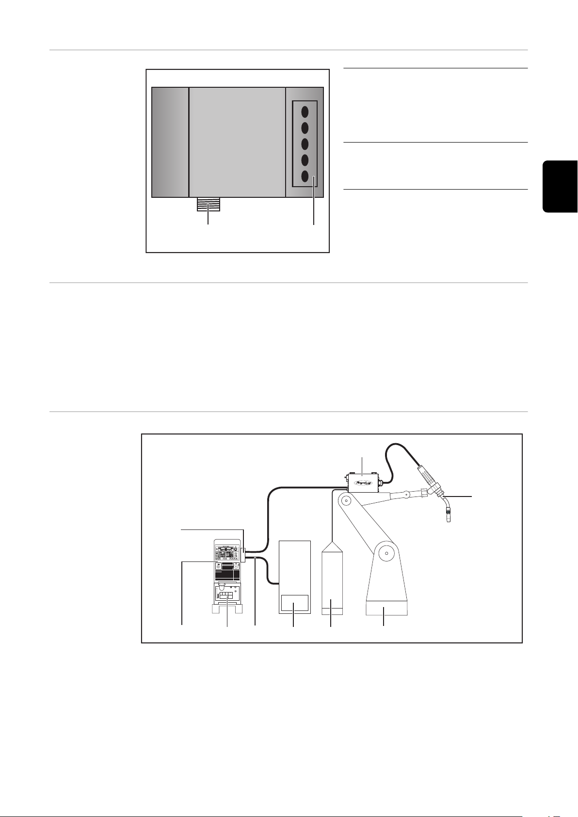
Raccordements
(2)
(1)
(1) (10)
(2)
(3)
(9)
(8) (7)
(6)
(5)
(4)
avec l’interface Série d’appareils
TS/TPS, MW/TT
(1) Anti-traction
pour le passage du câble de
données DeviceNet et de l’alimentation électrique du coupleur de bus de terrain
(2) Connecteur LocalNet
pour le branchement du faisceau de câbles intermédiaire.
FR
Raccordements avec l’interface
Consignes supplémentaires
Exemple d’utilisation - Série
d’appareils TS/
TPS, MW/TT
IMPORTANT! Tant que l’interface robot est connectée au LocalNet, le mode de
service « Mode 2 temps » reste automatiquement sélectionné (affichage : Mode 2
temps).
Vous trouverez des informations plus détaillées concernant le mode de soudage « Mode 2 temps spécial pour interface robot » dans les chapitres « Soudage
MIG/MAG » et « Paramètres Mode de service » des Instructions de service de la
source de courant.
(1) Source de courant
(2) DeviceNet
(3) Faisceau de liaison
(4) Dévidoir-fil
(5) Torche de soudage
(6) Robot
(7) Pack Marathon
(8) Commande robot
(9) Câble de données DeviceNet
(10) Refroidisseur
85
Page 86

Remarques relatives au montage
de la variante externe de l’interface
IMPORTANT! Lors du montage de la variante externe de l’interface, respecter les
prescriptions suivantes :
La pose des câbles doit s’effectuer séparément des lignes affectées au
-
réseau d’alimentation
Le montage du coupleur de bus doit s’effectuer séparément des lignes af-
-
fectées au réseau d’alimentation ou des composants relié à ce dernier
Le coupleur de bus de terrain doit être installé dans un endroit protégé de la
-
saleté et de l’eau
Veiller à ce que la tension d’alimentation 24 V soit séparée des circuits élec-
-
triques d’une tension supérieure.
86
Page 87

Raccorder et configurer le coupleur de bus de ter-
(1)
(2)
(3)
BK5200
BECKHOFF
(1)
(2)
(3)
rain
Sécurité
Connecteurs du
coupleur de bus
de terrain
AVERTISSEMENT!
Risque d'électrocution.
Cela peut entraîner des dommages corporels et matériels graves.
Avant d'entamer les travaux, déconnecter tous les appareils et composants
▶
concernés et les débrancher du réseau électrique.
S'assurer que tous les appareils et composants concernés ne peuvent pas
▶
être remis en marche.
Après ouverture de l'appareil, s'assurer, à l'aide d'un appareil de mesure ap-
▶
proprié, que les composants à charge électrique (condensateurs, par ex.)
sont déchargés.
FR
Connecter le
coupleur de bus
de terrain
Éléments du coupleur de bus de terrain BK5250
(1) Connecteur DeviceNet
(2) Sélecteur d’adresse / Réglage du taux de bauds
(3) Connecteurs pour l’alimentation électrique externe
IMPORTANT! L’alimentation électrique externe ne doit pas provenir de la source
de courant. Pour l’alimentation électrique externe, utiliser le robot ou la commande.
ATTENTION!
Risque d'électrocution.
Cela peut entraîner des dommages matériels graves.
Avant le début des travaux, s’assurer que le câble pour l’alimentation électri-
▶
que externe de l’interface soit hors tension et le demeure pendant toute la
durée des travaux.
Démonter le couvercle de l’interface
1
Démonter l’anti-traction de l’interface
2
Éléments du coupleur de bus de terrain BK5200
87
Page 88

Passer le câble de données DeviceNet et le câble pour l’alimentation électri-
V+
CAN_H
SHIELD
CAN_L
CAN_V-
Red P.M.S. #207C
White EIA 395 A within wire/cable limits
Blue P.M.S. #297C
Black P.M.S. #426C
3
que externe dans l’anti-traction par le passage pour câbles
Le câble de bus se compose d’un câble blindé et torsadé à 2x2 conducteurs. Les
deux paires de conducteurs sont respectivement destinées à
la transmission de données
-
l’alimentation électrique (en fonction du câble, des intensités de courant jus-
-
qu’à 8 Ampère sont possibles)
IMPORTANT! La longueur de câble maximale autorisée dépend du taux de
bauds. Selon le choix du taux de bauds, les longueurs de câble suivantes sont
possibles :
max. 100 m pour le taux de bauds le plus élevé (500 kbaud)
-
max. 500 m pour le taux de bauds le plus faible (125 kbaud)
-
Le branchement du câble de bus DeviceNet s’effectue au moyen de la fiche 5
pôles fournie. La broche 1 se trouve en haut sur le coupleur de bus.
Brancher les câbles de données conformément à l’illustration suivante en re-
4
spectant les pôles sur la broche 2 et la broche 4
REMARQUE! Mettre en place des résistances aux extrémités du câble de bus
de terrain, afin d’éviter les réflexions et les problèmes de transmission qui y
sont liés.
Brancher l’alimentation électrique en respectant les pôles sur la broche 1 et
5
la broche 5
Raccorder
6
- la broche 1 à la borne X1 / 24 V
- la broche 5 à la borne X1 / 0 V
IMPORTANT! Pour la mise en service, le raccordement des deux tensions est
nécessaire !
Connecteur DeviceNet avec positions de branchement correspondantes
BK5200 BK5250
Vendor ID 108 108
Device Type 12 12
Code produit 5200 5250
Groupe DeviceNet Groupe 2 Groupe 2
MajRev 3 1
88
Page 89

BK5200 BK5250
(1)
(2)
MinRev 0 1
ProdName - BK5250 V01.01
Brancher la connexion électrique entre le « rail profilé isolé » et le blindage
7
du câble de bus
IMPORTANT! Pour le montage du coupleur de bus de terrain, utiliser exclusivement des rails profilés « isolés ». Vérifier que le rail profilé n’ait aucun contact électrique avec la terre de la source de courant.
FR
Configuration
adresse esclave
BK5250
Raccorder le profilé chapeau avec le blindage du câble de bus - Série d’appareils TS/TransPuls Synergic,MW/TT
Vérifier si le blindage du côté du robot est bien relié à la terre du robot
8
Raccorder l’alimentation électrique externe du robot ou de la commande aux
9
connecteurs pour l’alimentation électrique externe sur le coupleur de bus de
terrain
Monter le câble de données DeviceNet et le câble pour l’alimentation électri-
10
que externe à l’aide d’attache-câbles dans l’anti-traction par le passage pour
câbles
Monter l’anti-traction sur l’interface avec le matériel de fixation original de
11
manière à ce que l’anti-traction reprenne sa position initiale
Sur série d’appareils TS/TransPuls Synergic, MW/TT:
Raccorder la prise LocalNet du faisceau de liaison à la connexion Localnet
12
sur l’interface
Régler l’adresse de l’esclave au moyen des deux sélecteurs.
Réglage par défaut = 11
Toutes les adresses sont admises, mais chaque adresse ne peut apparaître qu’une
fois sur le réseau.
S’assurer que tous les appareils et composants concernés sont débranchés
1
du secteur et sont déconnectés.
S’assurer que l’interface est débranchée du secteur
2
89
Page 90

À l’aide d’un tournevis, placer le commutateur dans la position souhaitée
0
1
2
3
4
5
6
7
8
9
0
1
2
3
4
5
6
7
8
9
x 1
x 10
3
le commutateur supérieur est un multiplicateur d’unités
-
le commutateur supérieur est un multiplicateur de dizaines
-
IMPORTANT! S’assurer que le commutateur est bien enclenché.
Exemple
Régler l’adresse 34 :
Sélecteur rotatif supérieur S520 :
-
4
Sélecteur rotatif inférieur S521 : 3
-
Remonter le couvercle de l’interface avec les vis d’origine de manière à ce
4
que la couvercle de l’interface reprenne sa position initiale
Configuration du
taux de bauds
BK5200
IMPORTANT! Avant la mise en service du coupleur de bus, régler le numéro de
noeud et le taux de bauds du coupleur de bus.
S’assurer que tous les appareils et composants concernés sont débranchés
1
du secteur et sont déconnectés.
S’assurer que l’interface est débranchée du secteur
2
Régler le MAC ID avec les commutateurs Dip 1 à 6 :
3
-
Commutateur 1 = bit minimal (20)
-
Commutateur 6 = bit maximal (25)
Le bit est activé si le commutateur se
trouve en position ON.
Le MAC ID est réglable selon une plage de 0 à 63.
Le réglage du taux de bauds s’effectue à l’aide des commutateurs 7 à 8. Le tableau suivant indique les différents réglages des taux de bauds.
Réglage du taux de bauds 1 2 3 4 5 6 7 8
125 kBd - - - - - - off off
250 kBd - - - - - - on off
500 kBd - - - - - - off on
(par defaut) 125 kBd - - - - - - on on
Remonter le couvercle de l’interface avec les vis d’origine de manière à ce
4
que la couvercle de l’interface reprenne sa position initiale
90
Page 91

Propriétés de la transmission de données
Technique de
transmission
Topologie du réseau
Bus linéaire, fermeture de bus aux deux extrémités (121 Ohm), câbles de dérivation possibles
Medium
Câble blindé torsadé à 2x2 conducteurs, le blindage doit être exécuté.
Nombre de stations
max. 64 participants
Longueur max. du bus
selon le taux de bauds réglé :
100 m pour 500 kBit/s, 250 m pour 250 kBit/s, 500 m pour 125 kBit/s
Vitesse de transmission
500 kBit/s, 250 kBit/s, 125 kBit/s
Connecteur
Open Style Connector 5 pôles
Modes de service
Bit Strobe, Polling, Cyclic, Change of State (COS)
Bande passante de données de processus
96 Bit (configuration standard)
Format de données de processus
Intel
FR
Dispositif de
sécurité
Pour que la source de courant puisse interrompre le processus en cas d’absence
de transmission de données, le noeud du bus de terrain dispose d’une surveillance de mise hors circuit. Si aucune transmission de données n’a lieu dans un délai
de 700 ms, toutes les entrées et sorties sont remises à zéro et la source de courant se trouve à l’état „Stop“. Après la reprise de la transmission de données a
lieu la reprise du processus par les signaux suivants :
Signal “Robot ready”
-
Signal “Valider la panne”
-
91
Page 92
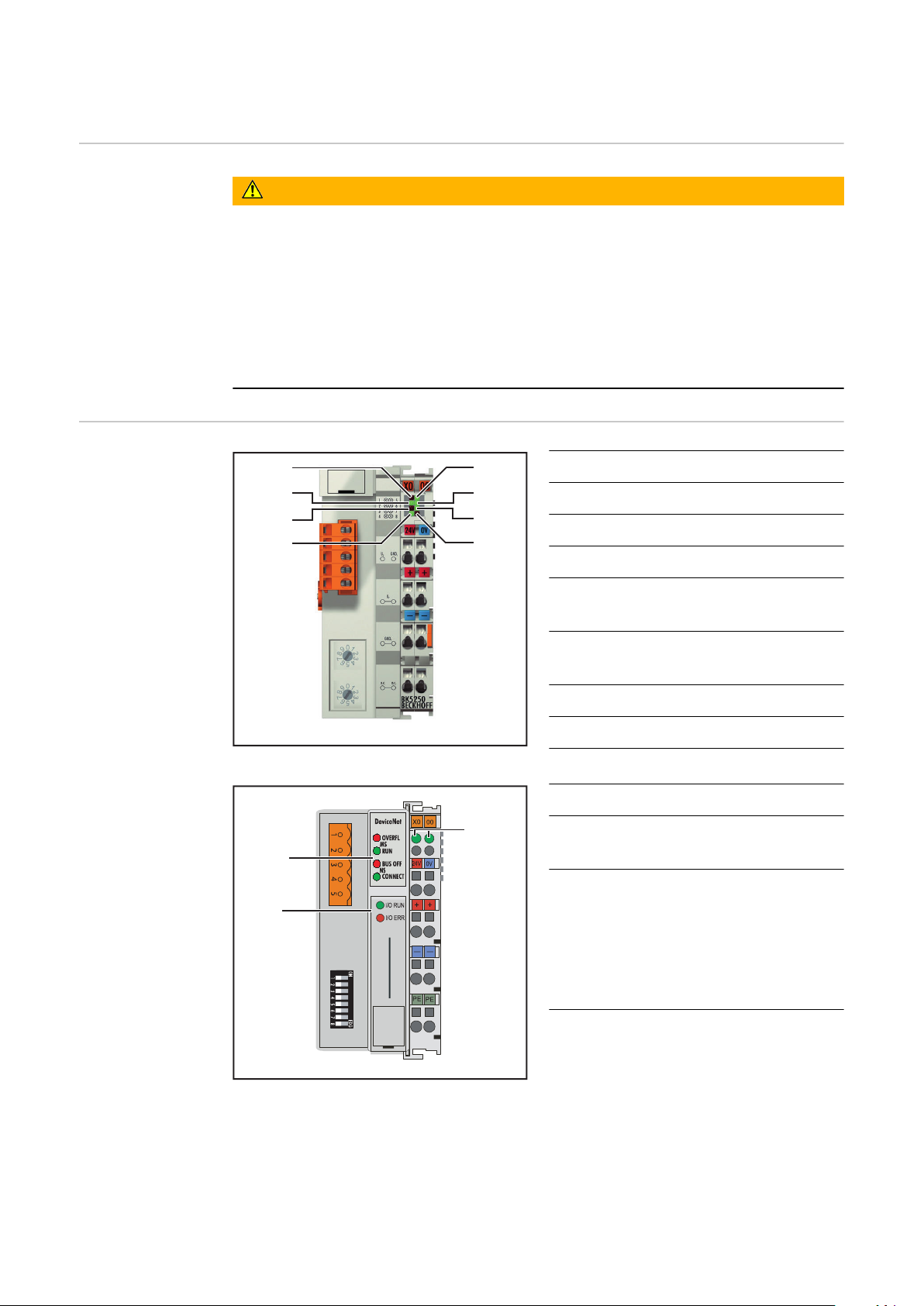
Diagnostic d’erreur, élimination de l'erreur
(5)
(6)
(7)
(8)
(1)
(2)
(3)
(4)
BK5200
BECKHOFF
(10)
(11)
(9)
Sécurité
Généralités
AVERTISSEMENT!
Risque d'électrocution.
Cela peut entraîner des dommages corporels et matériels graves.
Avant d'entamer les travaux, déconnecter tous les appareils et composants
▶
concernés et les débrancher du réseau électrique.
S'assurer que tous les appareils et composants concernés ne peuvent pas
▶
être remis en marche.
Après ouverture de l'appareil, s'assurer, à l'aide d'un appareil de mesure ap-
▶
proprié, que les composants à charge électrique (condensateurs, par ex.)
sont déchargés.
(1) DEL ADR (Module)
(2) DEL RUN (Module)
(3) DELTX Overflow (Net)
(4) DEL Overflow (Net)
(5) DEL Alimentation coupleur de
bus
(6) DEL Alimentation contacts
d’alimentation
(7) DEL Bus de bornes RUN
(8) DEL Bus de bornes ERR
Éléments du coupleur de bus de terrain BK5250
(9) Voyants DEL d’état de service
(10) Voyants DEL de statut du bus
de terrain
(11) Voyants DEL d’alimentation
DEL gauche ... indique l’ali-
-
mentation du coupleur de
bus de terrain
indique l’alimentation des
-
contacts d’alimentation
Éléments du coupleur de bus de terrain BK5200
Si une erreur se produit, les voyants DEL de statut du bus de terrain ou d’état de
service signalent le type d’erreur et l’endroit où elle s’est produite.
92
IMPORTANT! Après élimination de l’erreur, dans de nombreux cas, la séquence
de clignotement ne se termine pas au niveau du coupleur de bus de terrain.
Page 93
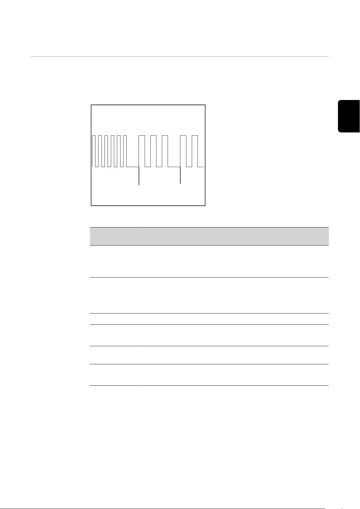
Redémarrer en éteignant et en rallumant l’alimentation électrique ou en réinitia-
(a) (b) (c)
lisant le logiciel du coupleur de bus de terrain.
K bus / operating
status LEDs (local errors)
Les voyants DEL du bus de bornes / d’état de service indiquent la communication locale entre le coupleur de bus de terrain et les bornes du bus de terrain. La
DEL verte s’allume si le fonctionnement est normal. La DEL rouge clignote avec
deux fréquences différentes si une erreur de bus se produit.
Clignotement rapide :
a)
Démarrage du code d’erreur
Première impulsion lente :
b)
Type d’erreur
Deuxième impulsion lente :
c)
FEmplacement de l’erreur
IMPORTANT! Le nombre d’impulsions
indique la position de la dernière borne
du bus de terrain avant la survenue de
l’erreur. Les bornes passives du bus de
terrain (par exemple bornes d’alimen-
Code de clignotement
tation) ne sont pas incluses dans ce
nombre.
Code d’erreur
Explication
de l’erreur Description
FR
1 impulsion 0 Erreur du total de contrôle EEPROM
1 Dépassement Inline-Code-Buffer
2 Type de données inconnu
2 impulsions
0
Configuration programmée
Entrée du tableau incorrecte / Coupleur de
bus
n (n<0) Comparaison tableau borne(s) incorrecte
3 impulsions 0 Erreur de commande bus de bornes
4 impulsions 0 Erreur de données bus de bornes
n (n<0) Interruption derrière borne(s) (0 : coupleur)
5 impulsions n (n<0) Erreur bus de bornes lors de la communication
de registre avec borne(s)
6 impulsions 0 Erreur spécifique bus de terrain
n (n<0)
IMPORTANT! When an error occurs during operation, the error code is not
immediately indicated on the LEDs. The bus coupler must be requested to perform a diagnosis of the bus terminals. The diagnosis request is generated after
switching on, or is requested by the master.
93
Page 94

Voyants DEL de
statut du bus de
terrain
Les voyants DEL de statut de bus de terrain indiquent les états de service du bus
de terrain.
Module Statut
DEL „MS RUN“ La DEL verte
- clignote
- est allumée en continu
DEL „MS OVERFL“ La DEL rouge
- clignote
- est allumée en continu
Réseau Statut
DEL „NS CONNECT“ La DEL verte
- clignote Coupleur de bus prêt pour la communi-
DEL „NS BUS OFF“ La DEL verte
- est allumée en continu Coupleur de bus relié au maître,
DEL „NS BUS OFF“ La DEL rouge
- clignote
- est allumée en continu
Configuration incorrecte
Statut OK
Dépassement de la Receive-Queue
Statut OK
cation, mais non relié au maître
l’échange de données a lieu
Connexion E/S en Time-out
BUS OFF : Erreur CAN, participants
avec adresse de noeud identique
94
Page 95

Description des signaux DeviceNet/DeviceNet
BK 5200
BK 5250
KL6021-0010
KL9010
Twin
Généralités Les descriptions de signaux suivantes s’appliquent à une interface avec une bor-
ne de communication KL 6021-0010 (exécution standard)
Il existe en plus la possibilité d’intégrer d’autres bornes supplémentaires dans
une interface robot. Le nombre est toutefois limité par la taille du boîtier.
IMPORTANT! En cas d’intégration d’autres bornes, le modèle de données du
processus est modifié.
FR
Modes de service
de la source de
courant - Série
d’appareils TS/
TPS, MW/TT
Aperçu La « Description des signaux DeviceNet/DeviceNet Twin » se compose des sec-
En fonction du mode de service sélectionné, l’interface DeviceNet/DeviceNet
Twin peut transmettre des signaux d’entrée et de sortie très différents.
Mode de service E05 E04 E03
Soudage MIG/MAG Standard 0 0 0
Soudage arc pulsé MIG/MAG 0 0 1
Mode job 0 1 0
Sélection de paramètres internes 0 1 1
TIG 1 1 0
CC/CV 1 0 1
Soudage standard manuel 1 0 0
CMT / Procédé spécial 1 1 1
tions suivantes :
Signaux d’entrée et de sortie pour MIG/MAG - Série d’appareils TS/
-
TPS,MW/TT
Signaux d’entrée et de sortie pour TIG - Série d’appareils TS/TPS,MW/TT
-
Signaux d’entrée et de sortie pour CC/CV - Série d’appareils TS/TPS,MW/TT
-
Signaux d’entrée et de sortie pour manuel standard - Série d’appareils TS/
-
TPS,MW/TT
Signaux d’entrée et de sortie pour MIG/MAG Twin DeviceNet - Série d’appa-
-
reils TS/TPS,MW/TT
Signaux d’entrée et de sortie pour MIG/MAG Twin DeviceNet John Deere -
-
Série d’appareils TS/TPS,MW/TT
95
Page 96

Signaux d’entrée et de sortie pour MIG/MAG Série d’appareils TS/TPS, MW/T
Signaux d’entrée
(du robot vers la
source de courant)
N° d’ordre Description du signal Plage Activité
E01 Soudage activé - High
E02 Robot prêt - High
E03 Modes de service Bit 0 - High
E04 Modes de service Bit 1 - High
E05 Modes de service Bit 2 - High
E06 Identification maître Twin - High
E07 - E08 Non utilisé - -
E09 Gas Test - High
E10 Amenée de fil - High
E11 Retour de fil - High
E12 Valider la panne de source - High
E13 Recherche de position - High
E14 Soufflage torche - High
E15 - E 16 Non utilisé - -
E17 - E24 Numéro de tâche 0 - 99 -
E25 - E31 Numéro de programme 0 - 127 -
E32 Simulation du soudage - High
Avec la commande à distance RCU 5000i et en mode de service
Mode Tâche
E17 - E23 Numéro de tâche 0 - 999 -
E32 Simulation du soudage - High
Puissance (valeur de consigne) 0 - 65535
(0 % - 100 %)
E33 - E40 Low Byte - -
E41 - E48 High Byte - -
Correction de la longueur de
l’arc électrique (valeur de consigne)
E49 - E56 Low Byte - -
E57 - E64 High Byte - -
0 - 65535
(-30 % - +30 %)
-
-
96
E65 - E72 Correction arc pulsé / dynami-
que (valeur de consigne)
0 - 255
(-5 % - +5 %)
-
Page 97

N° d’ordre Description du signal Plage Activité
Signaux de sortie (de la source
de courant vers
le robot)
E73 - E80 Brûlure retour (valeur de consi-
gne)
E81 Synchro Puls disable - High
E82 SFI disable - High
E83 Correction arc pulsé / dynami-
que disable
E84 Brûlure retour disable - High
E85 Plage totale de puissance (0 -
30 m)
E86 Non utilisé - -
E87 - E96 Vitesse de soudage 0 - 1023
N° d’ordre Description du signal Plage Activité
A01 Arc électrique stable - High
A02 Signal limite (uniquement en re-
lation avec RCU5000i)
0 - 255
(-200 ms - +200
ms)
- High
- High
(0 - 1023 cm/min)
- High
-
-
FR
A03 Processus actif - High
A04 Signal de courant principal - High
A05 Protection collision torche - High
A06 Source de courant prête - High
A07 Communication prête - High
A08 Réserve - -
A09 - A16 Numéro d’erreur 0 - 255 -
A17 - A24 Non utilisé - -
A25 Contrôle collage du fil
(collage détaché)
A26 Non utilisé - -
A27 Accès robot (uniquement en re-
lation avec RCU 5000i)
A28 Fil disponible - High
A29 Durée dépassée court-circuit - High
A30 Documentation données prête - High
A31 Non utilisé - -
- High
- High
A32 Puissance hors plage - -
Tension de soudage (valeur réelle)
A33 - A40 Low Byte - -
0 - 65535
(0 - 100 V)
-
97
Page 98

N° d’ordre Description du signal Plage Activité
A41 - A48 High Byte - -
Courant de soudage (valeur
réelle)
A49 - A56 Low Byte - -
A57 - A64 High Byte - -
A65 - A72 Courant moteur (valeur réelle) 0 - 255
A73 - A80 Non utilisé - -
Vitesse du fil (valeur réelle) 0 - 65535
A81 - A88 Low Byte - -
A89 - A96 High Byte - -
0 - 65535
(0 - 1000 A)
(0 - 5 A)
(-327,68 - +327,67
m/min)
-
-
98
Page 99

Signaux d’entrée et de sortie pour TIG - Série
d’appareils TS/TPS, MW/TT
Signaux d’entrée
(du robot vers la
source de courant)
N° d’ordre Description du signal Plage Activité
E01 Soudage activé - High
E02 Robot prêt - High
E03 Modes de service Bit 0 - High
E04 Modes de service Bit 1 - High
E05 Modes de service Bit 2 - High
E06 Identification maître Twin - -
E07 - E08 Non utilisés - -
E09 Gas Test - High
E10 Amenée de fil - High
E11 Retour de fil - High
E12 Valider la panne de source - High
E13 Recherche de position - High
E14 KD disable - High
E15 - E16 Non utilisés - -
E17 - E24 Numéro de tâche 0 - 99 -
FR
E25 DC / AC - High
E26 DC- / DC+ - High
E27 Formation de calotte - High
E28 Impulsions disable - High
E29 Sélection plage d’impulsion Bit 0 - High
E30 Sélection plage d’impulsion Bit 1 - High
E31 Sélection plage d’impulsion Bit 2 - High
E32 Simulation du soudage - High
Courant principal (valeur de consi-
gne)
E33 - E40 Low Byte - -
E41 - E48 High Byte - -
Paramètre externe (valeur de con-
signe)
E49 - E56 Low Byte - -
E57 - E64 High Byte - -
0 - 65535
(0 bis I
0 - 65535 -
max
)
-
E65 - E72 Courant de base disable 0 - 255
(0% - 100%)
-
99
Page 100

N° d’ordre Description du signal Plage Activité
Réglage de la
plage d’impulsion TIG
E73 - E80 Duty Cycle (valeur de consigne) 0 - 255
-
(10% - 90%)
E81 - E82 Non utilisés - -
E83 Courant de base disable - High
E84 Duty Cycle disable - High
E85 - E86 Non utilisés - -
E87 - E96 Vitesse d’avance du fil (valeur de
consigne)
0 - 1023
(0 - vD
max
-
)
Mode de service E31 E30 E29
Régler la plage d’impulsion au niveau de la source de
0 0 0
courant
Plage de réglage impulsion désactivée 0 0 1
0,2 - 2 Hz 0 1 0
2 - 20 Hz 0 1 1
20 - 200 Hz 1 0 0
Signaux de sortie (de la source
de courant vers
le robot)
200 - 2000 Hz 1 0 1
N° d’ordre Description du signal Plage Activité
A01 Arc électrique stable - High
A02 Non utilisé - -
A03 Processus actif - High
A04 Signal de courant principal - High
A05 Protection collision torche - High
A06 Source de courant prête - High
A07 Communication prête - High
A08 Réserve - -
A09 - A16 Numéro d’erreur 0 - 255
A17 - A25 Non utilisés - -
A26 Haute fréquence active - High
A27 Non utilisé - -
100
A28 Fil disponible - High
A29 - A30 Non utilisés - -
A31 Puls High - High
A32 Non utilisé - -
 Loading...