

Page 1
Installation Instructions
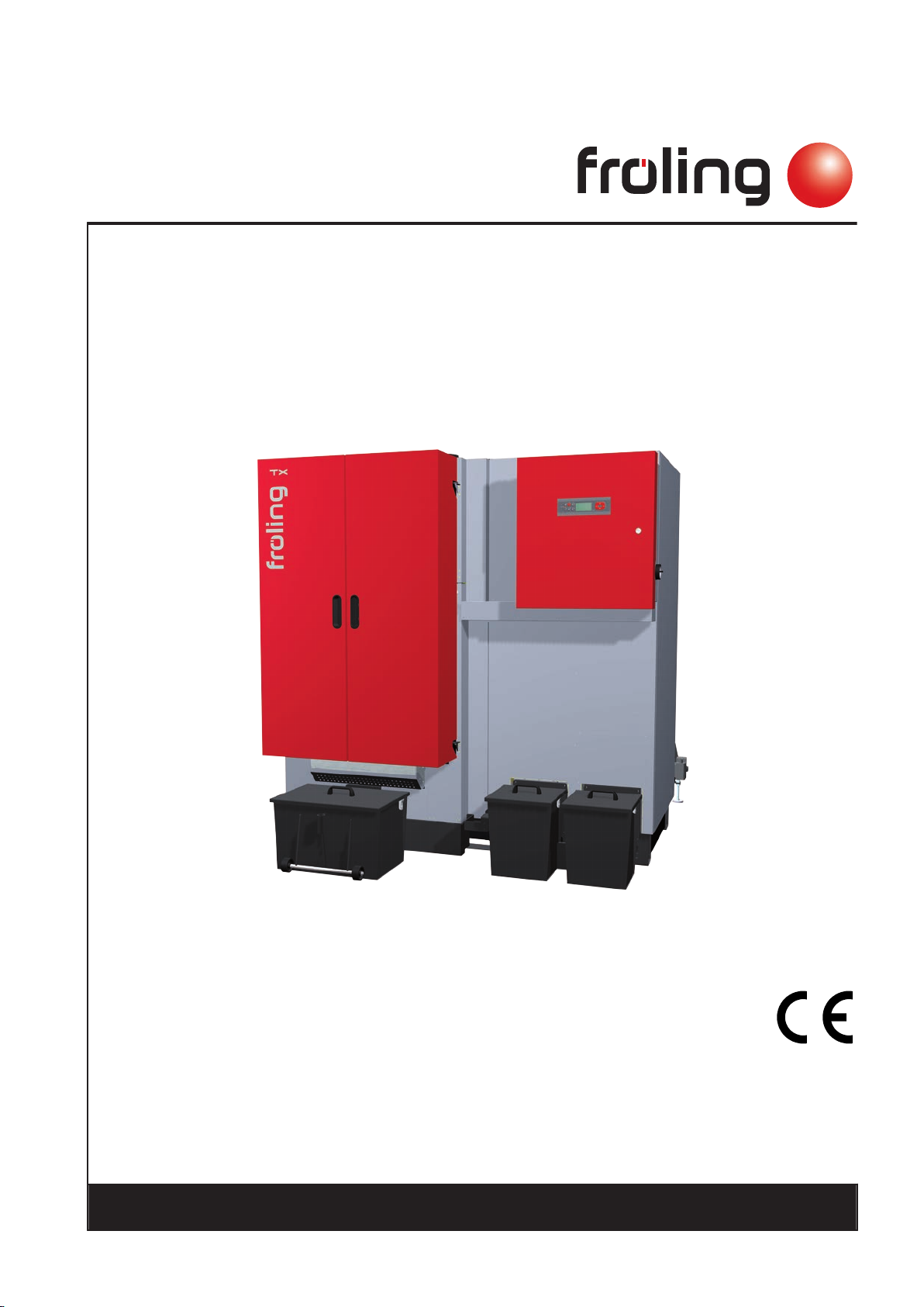
Wood chip boiler TX 150-250
Translation of the original German operating instructions for technicians!
Read and follow the instructions and safety information!
Technical changes, typographical errors and omissions reserved!
M1320112_en | Edition 08/04/2013
Froling GesmbH | A-4710 Grieskirchen, Industriestraße 12 | www.froling.com
Page 2

Contents
Contents
1 General 4
2 Safety 5
2.1 Hazard levels of warnings 5
2.2 Qualification of assembly staff 6
2.3 Protective equipment for assembly staff 6
2.4 Design Information 7
2.4.1 Notes on standards 7
2.4.2 Installation and approval of the heating system 8
2.4.3 General information for installation room (boiler room) 8
2.4.4 Requirements for central heating water 9
2.4.5 Return lift 9
2.4.6 Use with storage tank 10
2.4.7 Chimney connection/chimney system 10
General standards for heating systems
Standards for structural and safety devices
Standards for heating water
Standards for permitted fuels
Draught limiter
Boiler data for planning the flue gas system
7
7
7
8
10
11
3 Technology 12
3.1 Dimensions 12
3.2 Technical specifications 13
4 Assembly 15
4.1 Transport 15
4.2 Positioning 15
4.3 Temporary storage 15
4.4 Set-up in the boiler room 15
4.4.1 Moving the boiler in the boiler room 15
4.4.2 Minimum distances in the boiler room 16
4.5 Mounting steps 17
4.5.1 General information 17
4.5.2 Screwing the fire box with the heat exchanger 18
4.5.3 Installing sensor of thermal discharge system 19
4.5.4 Assembly of fireclay blocks 20
4.5.5 Preparation of flue gas recirculation connection (Option) 21
4.5.6 Retrofitting the WOS bar (if necessary) 22
4.5.7 Installing lower main frame of insulation 23
4.5.8 Installing upper main frame of insulation 24
4.5.9 Installing the frame for the insulating door 25
4.5.10 Installing the insulating side panels 26
4.5.11 Complete the heat exchanger cover and the combustion chamber door 29
4.5.12 Check grate settings and install the tipping grate motor 31
4.5.13 Installing the fire box ash removal unit 33
4.5.14 Installing the switch cabinet and cable ducts 37
4.5.15 Installing the stoker unit 39
4.5.16 Installing the automatic igniter 40
2 Froling GesmbH | A-4710 Grieskirchen, Industriestraße 12 | www.froling.com
Page 3

Contents
4.5.17 Installing the actuators of the air flaps 41
4.5.18 Installing overpressure monitor and temperature sensor 42
4.5.19 Installing the underpressure measurement 43
4.5.20 Installing the WOS drive 44
4.5.21 Heat exchanger ash removal unit with ash box 46
4.5.22 Heat exchanger ash removal unit with ash screw (optional) 47
4.5.23 Installing the combustion air blower fan 54
4.5.24 Installing the STL and the boiler sensor 55
4.5.25 Installing the ID fan 56
4.5.26 Installing the FGR air box (optional) 57
4.5.27 Installing the flue gas recirculation FGR (optional) 58
4.5.28 Installing insulating door and cover plates 60
4.6 Electrical connection 61
4.6.1 Installing insulating covers and cover plates 61
4.7 Connecting the thermal discharge system 64
5 Start-up 65
5.1 Before commissioning / configuring the boiler 65
5.2 Initial startup 66
5.2.1 Permitted fuels 66
5.2.2 Heating up for the first time 66
Wood pellets
Wood chips
66
66
6 Decommissioning 67
6.1 Mothballing 67
6.2 Disassembly 67
6.3 Disposal 67
7 Appendix 68
7.1 Addresses 68
7.1.1 Address of manufacturer 68
7.1.2 Address of the installer 68
Installation Instructions TX 150-250 | M1320112_en 3
Page 4

1
1 General
Issuing a delivery cer‐
tificate
General
Thank you for choosing a quality product from Froling. The product features a state-ofthe-art design and conforms to all currently applicable standards and testing guide‐
lines.
Please read and observe the documentation provided and always keep it close to the
system for reference. It contains important safety information and all the operation and
maintenance specifications needed to operate the system safely, properly, environ‐
mentally friendly and cost-effectively.
The constant further development of our products means that there may be minor dif‐
ferences from the pictures and content. If you discover any errors, please let us know:
[email protected]
Subject to technical change.
The EC Declaration of Conformity is only valid in conjunction with a delivery certificate,
which has been filled in correctly and signed as part of the commissioning process.
The original document remains at the installation site. Commissioning installers or
heating engineers are requested to return a copy of the delivery certificate together
with the guarantee card to Froling. On commissioning by FROLING Customer Service
the validity of the delivery certificate will be noted on the customer service record.
4 Froling GesmbH | A-4710 Grieskirchen, Industriestraße 12 | www.froling.com
Page 5
Safety
Hazard levels of warnings
2 Safety
2.1 Hazard levels of warnings
This documentation uses warnings with the following hazard levels to indicate direct
hazards and important safety instructions:
DANGER
2
The dangerous situation is imminent and if measures are not observed it will lead
to serious injury or death. You must follow the instructions!
WARNING
The dangerous situation may occur and if measures are not observed it will lead
to serious injury or death. Work with extreme care.
CAUTION
The dangerous situation may occur and if measures are not observed it will lead
to minor injuries or damage to property.
Installation Instructions TX 150-250 | M1320112_en 5
Page 6
2
2.2 Qualification of assembly staff
CAUTION
Assembly and installation by untrained personnel:
Risk of personal injury and damage to property.
During assembly and installation:
❒ Observe the instructions and information in the manuals
❒ Only allow trained staff to carry out assembly and installation
Assembly, installation, initial startup and servicing must always be carried out by quali‐
fied personnel:
- Heating technician / building technician
- Electrical installation technician
- Froling customer services
The assembly staff must have read and understood the instructions in the documenta‐
tion.
Safety
Qualification of assembly staff
2.3 Protective equipment for assembly staff
You must ensure that staff have the protective equipment specified by accident pre‐
vention regulations.
▪ For transportation, setup and assembly:
- suitable workwear
- protective gloves
- sturdy shoes
6 Froling GesmbH | A-4710 Grieskirchen, Industriestraße 12 | www.froling.com
Page 7
Safety
Design Information
2.4 Design Information
2.4.1 Notes on standards
The system must be installed and commissioned in accordance with the local fire and
building regulations. The following standards and regulations should always be ob‐
served:
General standards for heating systems
2
EN 303-5 Boilers for solid fuels, manually and automatically fed combus‐
tion systems, nominal output up to 300 kW
EN 12828 Heating systems in buildings - Design of water-based heating
systems
EN 13384-1 Chimneys - Thermal and fluid dynamic calculation methods
Part 1: Chimneys serving one appliance
ÖNORM M 7510-1 Guidelines for checking central heating systems
Part 1: General requirements and one-off inspections
ÖNORM M 7510-4 Guidelines for checking central heating systems
Part 4: Simple check for heating plants for solid fuels
Standards for structural and safety devices
ÖNORM H 5170 Heating installation - Requirements for construction and safety
engineering, as well as fire prevention and environmental pro‐
tection
TRVB H 118 Technical directives for fire protection/prevention (Austria)
Standards for heating water
ÖNORM H 5195-1 Prevention of damage by corrosion and scale formation in
closed warm water heating systems at operating temperatures
up to 100 °C (Austria).
VDI 2035 Sheet 1 Prevention of damage in water heating systems - Scale forma‐
tion in domestic water heating systems and hot water heating
systems (Germany)
SWKI 97-1 Water quality for heating, steam, cooling and air conditioning
systems (Switzerland)
D.P.R. no. 412 Regulations for the planning, installation, running/operation and
maintenance of heating systems in buildings to reduce energy
consumption with reference to Article 4, Comma 4 of the Legis‐
lative Decree of 9 January 1991, No. 10 (Italy)
Installation Instructions TX 150-250 | M1320112_en 7
Page 8

2
2.4.2 Installation and approval of the heating system
Note on standards
Safety
Design Information
Standards for permitted fuels
EN 14961-2 Solid biofuel, fuel specifications and classes.
Part 2: Wood pellets for non-industrial use
EN 14961-4 Solid biofuel, fuel specifications and classes.
Part 2: Wood chips for non-industrial use
1. BImSchV First Ordinance of the German Federal Government for imple‐
mentation of the Federal Emission Protection Law, BGBl. I P.
491, in the applicable version.
The boiler should be operated in a closed heating system. The following standards
govern the installation:
ÖNORM / DIN EN 12828 Heating Systems in Buildings
NOTICE! Each heating system must be officially approved.
The appropriate supervisory authority (inspection agency) must always be informed
when installing or modifying a heating system, and authorisation must be obtained
from the building authorities:
Austria: Inform the civic/municipal building authorities.
Germany: Notify an approved chimney sweep and the building authorities.
2.4.3 General information for installation room (boiler room)
Boiler room characteristics
▪ There must not be a potentially explosive atmosphere in the boiler room as the
boiler is not suitable for use in potentially explosive environments.
▪ The boiler room must be frost-free.
▪ The boiler does not provide any light, so the customer must provide sufficient light‐
ing in the boiler room in accordance with national workplace design regulations.
▪ When using the boiler over 2000 metres above sea level you should consult the
manufacturer.
▪ Danger of fire due to flammable materials.
No flammable materials should be stored near the boiler. Flammable objects (e.g.
clothing) must not be put on the boiler to dry.
▪ Damage due to impurities in combustion air.
Do not use any solvents or cleaning agents containing chlorine in the room where
the boiler is installed.
▪ Keep the air suction opening of the boiler free from dust.
Ventilation of the boiler room
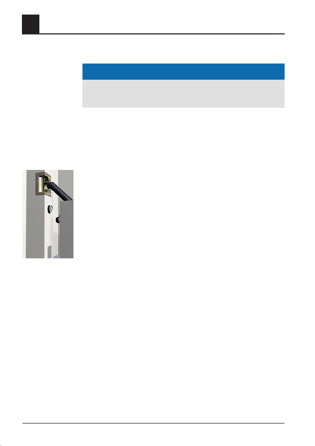
Ventilation air for the boiler room should be taken from and expelled directly outside,
and the openings and air ducts should be designed to prevent weather conditions (foli‐
age, snowdrifts, etc.) from obstructing the air flow.
8 Froling GesmbH | A-4710 Grieskirchen, Industriestraße 12 | www.froling.com
Page 9
Safety
Design Information
Note on standards
2.4.4 Requirements for central heating water
Note on standards
2
Unless otherwise specified in the applicable building regulations for the boiler room,
the following standards apply to the design and dimensions of the air ducts:
ÖNORM H 5170 - Construction and fire protection requirements
TRVB H118 - Technical directives on fire protection/prevention
The following standards and guidelines apply:
Austria:
Germany:
Switzerland:
Italy:
NOTICE! Note on filling with make-up water: Always bleed the filling hose before con‐
necting, in order to prevent air from entering the system.
ÖNORM H 5195-1
VDI 2035
SWKI 97-1
D.P.R. no. 412
2.4.5 Return lift
If the hot water return is below the minimum return temperature, some of the hot water
outfeed will be mixed in.
CAUTION
Risk of dropping below dew point/condensation formation if operated without re‐
turn temperature control.
Condensation water forms an aggressive condensate when combined with com‐
bustion residue, leading to damage to the boiler.
Take the following precautions:
❒ Regulations stipulate the use of a return temperature control.
➥ The minimum return temperature is 65 °C. We recommend fitting some
sort of control device (e.g. thermometer).
Installation Instructions TX 150-250 | M1320112_en 9
Page 10
2
Safety
Design Information
2.4.6 Use with storage tank
NOTICE
In principle it is not necessary to use a storage tank for the system to run smooth‐
ly. However we recommend that you use the system with a storage tank, as this
ensures a continuous supply of fuel in the ideal output range of the boiler.
For the correct dimensions of the storage tank and the line insulation (in accordance
with ÖNORM M 7510 or guideline UZ37) please consult your installer or Froling.
⇨ See "Addresses" [page 68]
2.4.7 Chimney connection/chimney system
EN 303-5 specifies that the entire flue gas system must be designed to prevent, wher‐
ever possible, damage caused by seepage, insufficient feed pressure and condensa‐
tion. Please note in this respect that flue gas temperatures lower than 160K above
room temperature can occur in the permitted operating range of the boiler.
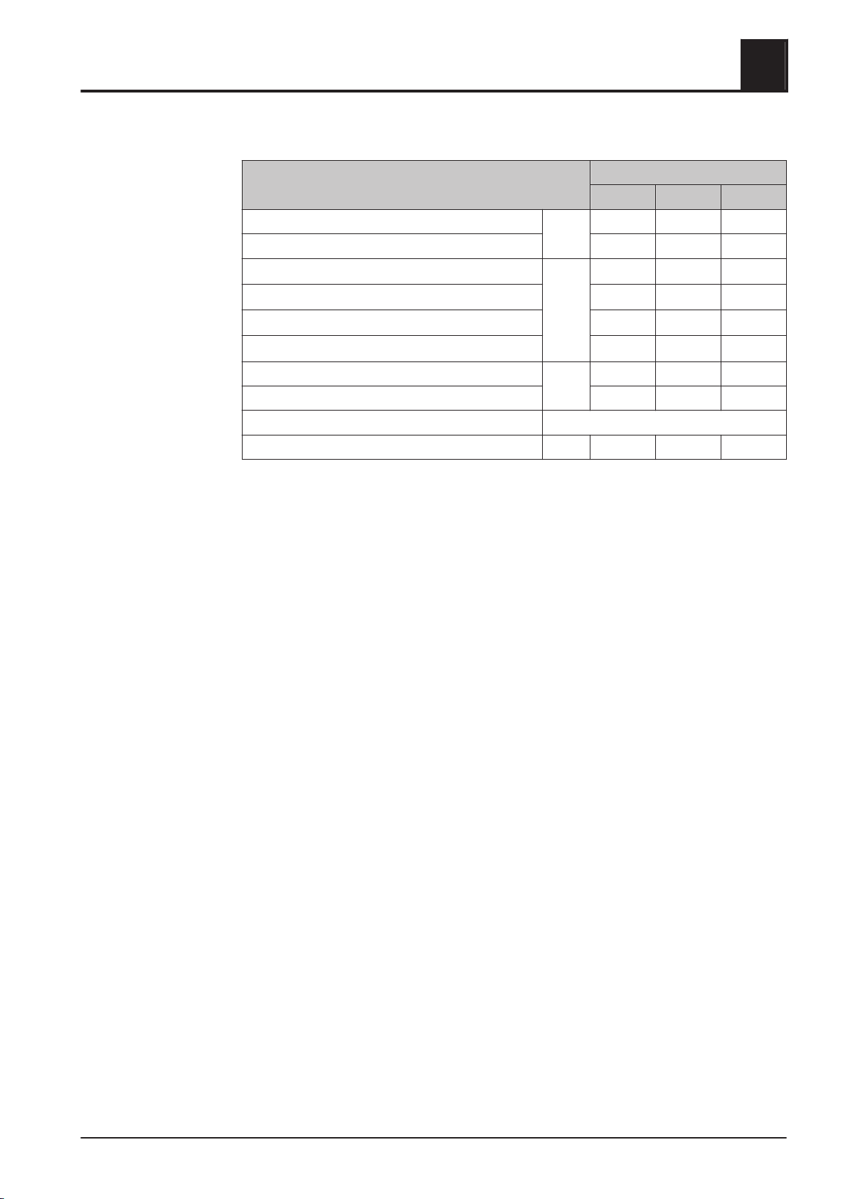
The flue gas temperatures (for clean systems) and additional flue gas values can be
found in the table below.
The connection between the boiler and the chimney system should be as short as
possible. The upward angle of the connection should not exceed 30 - 45°. Insulate the
connection. The entire flue gas system - chimney and connection - should be calcula‐
ted in accordance with EN 13384-1.
Local regulations and other statutory regulations also apply.
NOTICE! The chimney must be authorised by a smoke trap sweeper or chimney
sweep.
NOTICE! TRVB H 118 (Austria only) stipulates that an explosion flap must be installed
in the connecting piece (flue pipe) directly next to the boiler. It should be situated in
such a way that is poses no risk to persons!
Draught limiter
10 Froling GesmbH | A-4710 Grieskirchen, Industriestraße 12 | www.froling.com
The installation of a draught limiter is recommended.
NOTICE! Install the draught limiter directly under the mouth of the flue line, as the
pressure is constantly low at this point.
Page 11
Safety
Design Information
2
Boiler data for planning the flue gas system
Description TX
150 200 250
Flue gas temperature at nominal load °C 150 150 150
Flue gas temperature at partial load 110 110 110
Flue gas mass flow - wood chips W30, 13% O
Flue gas mass flow - wood chips W30, 9% O
Flue gas mass flow - pellets 13% O
Flue gas mass flow - pellets 9% O
2
2
2
2
kg/h 665 882 1108
420 557 700
559 741 931
355 471 591
Required feed pressure at nominal load mbar 0,05 0,05 0,05
Required feed pressure at partial load 0,02 0,02 0,02
Maximum permissible feed pressure gem. ÖNORM / DIN EN 303-5
Flue pipe diameter mm 200 250 250
Installation Instructions TX 150-250 | M1320112_en 11
Page 12
3
3 Technology
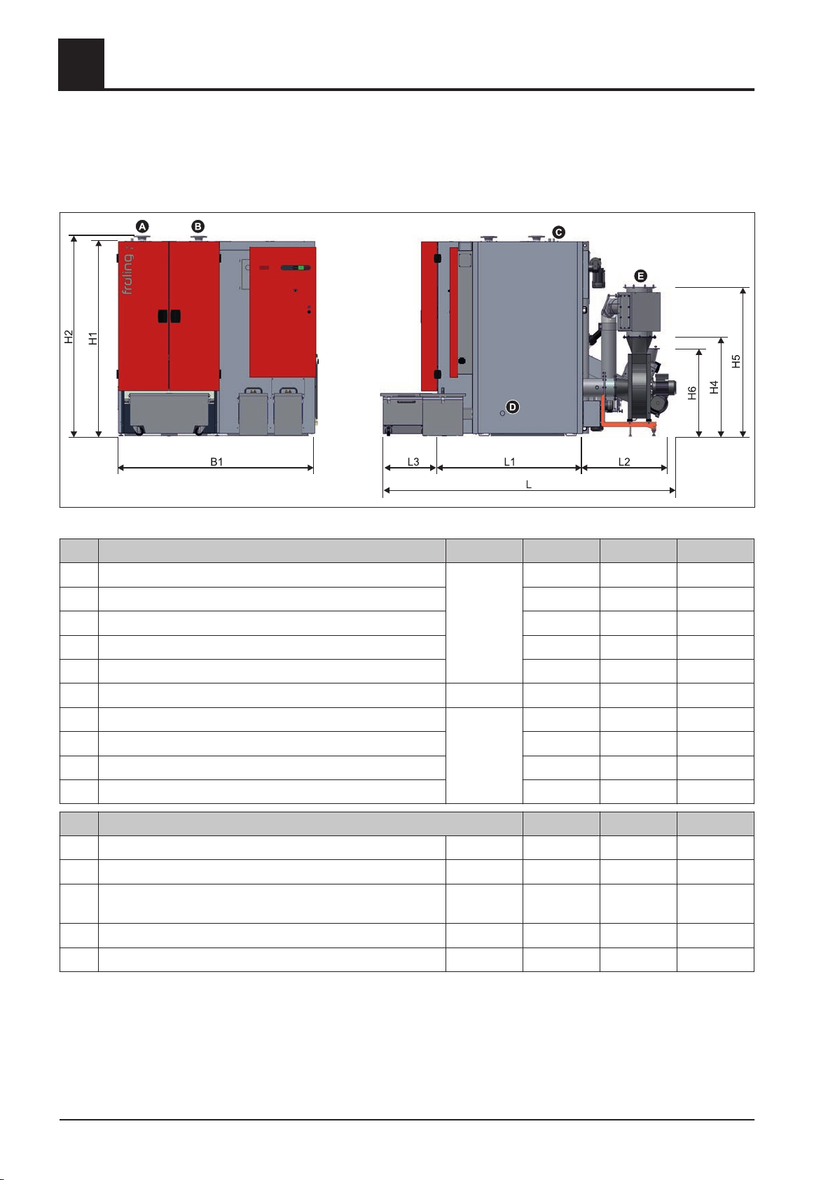
3.1 Dimensions
Technology
Dimensions
Item Description Unit TX 150 TX 200 TX 250
H1 Height, boiler mm 1880 1880 1880
H2 Height, flow and return connection 1935 1935 1935
H4 Height, flue pipe connection without FGR 770 960 960
H5 Height, flue pipe connection without FGR 1410 1445 1445
H6 Height, stoker unit with rotary valve 790 865 865
B1 Overall width mm 1970 2070 2070
L Length, boiler mm 2620 2980 2980
L1 Length, retort 1090 1400 1400
L2 Length, stoker unit 940 970 970
L3 Length, ash box 590 610 610
Item Description TX 150 TX 200 TX 250
A Boiler outfeed connection Inch 2½ 2½ 2½
B Boiler return connection Inch 2½ 2½ 2½
C Connection of thermal discharge safety device (near boiler
flow connection)
Inch ½ ½ ½
D Boiler drainage connection Inch ¾ ¾ ¾
E Flue pipe connection mm 200 250 250
12 Froling GesmbH | A-4710 Grieskirchen, Industriestraße 12 | www.froling.com
Page 13
Technology
Technical specifications
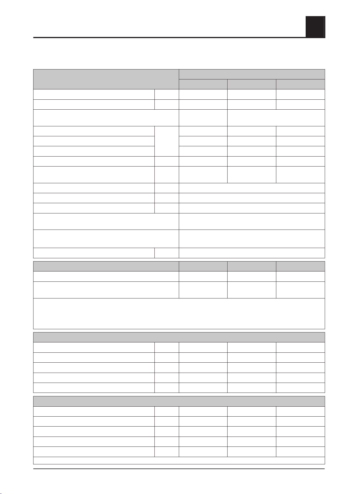
3.2 Technical specifications
Description TX
150 200 250
Rated heat output kW 150 199 250
Output range kW 45 – 150 59 - 199 75 – 250
3
Electrical connection 400V / 50Hz /
400V / 50Hz / C35A
C20A
Total weight of boiler kg 2730 3390 3390
Weight – retort 855 1120 1120
Weight - heat exchanger 1000 1280 1280
Boiler capacity (water) l 440 570 570
Water pressure drop
mbar 36 / 12 55 / 18 74 / 25
(ΔT = 10 / 20 K)
Min. boiler return temperature °C 65
Max. permitted operating temperature °C 90
Permitted operating pressure bar 3
Boiler class as per EN 303-5:1999
3 (5)
(pr EN 303-5:2012)
Permitted fuel as per EN 14961
1)
Part 2: Wood pellets class A1 / D06
Part 4: Wood chips class A2 / P16A-P45A
Airborne sound level dB(A) < 70
150 200 250
Testing institute
TÜV
2)
TÜV
3) 4)
TÜV
2)
Test report no. 10-UW/Wels-
EX-119
1.Detailed information on the fuel is included in the operating instructions, in the section on "Permitted fuels"
2.
TÜV Austria Services GmbH, Geschäftsbereich Umweltschutz, Am Thalbach 15, A-4600 Thalheim/Wels
3.As per EN 303-5, Section 5.1.3 type test: for a boiler from a range with a consistent structure it is sufficient, if the ratio of rated heat output from the largest to the smallest boiler ≤2 : 1,
to carry out the tests with the smallest and the largest boilers. The boiler manufacturer must ensure that all boilers, including those that have not been tested in the range, whose
values have been determined depending on the rated heat output by interpolation, fulfil the requirements of the norm
4.Values for the types TX 200 are interpolated between the types TX 150 and TX 250, test protocol 10-UW/Wels-EX-119 and 11-UW/Wels-EX-249!
13-U-032/SD 11-UW/Wels-
EX-249
Test data wood chips - Emissions in [mg/MJ] (RL / PL)
Carbon monoxide (CO) mg/MJ <4 / 35 5 / 33 7 / 30
Nitrous oxide (NOx) mg/MJ 78 / 63 74 / 61 69 / 58
Organic hydrocarbons (OGC) mg/MJ <1 / <1 <1 / <2 <1 / <2
Dust mg/MJ 23 / 15 20 / 17 17 / 19
Boiler efficiency % 92,1 / 92,3 92,9 / 92,5 93,7 / 92,8
Test data wood chips - Emissions in [mg/m³]1) (RL / PL)
Carbon monoxide (CO) mg/m³ <6 / 52 8 / 48 11 / 44
Nitrous oxide (NOx) mg/m³ 115 / 93 108 / 89 101 / 85
Organic hydrocarbons (OGC) mg/m³ <1 / <2 <1 / <2 <1 / <2
Dust mg/m³ 34 / 22 29 / 25 25 / 28
Boiler efficiency % 92,1 / 92,3 92,9 / 92,5 93,7 / 92,8
1.Emissions values based on dry flue gas at standard temperature and pressure (0°C, 1013 mbar) with a volume content of oxygen of 13%
Installation Instructions TX 150-250 | M1320112_en 13
Page 14
Technology
3
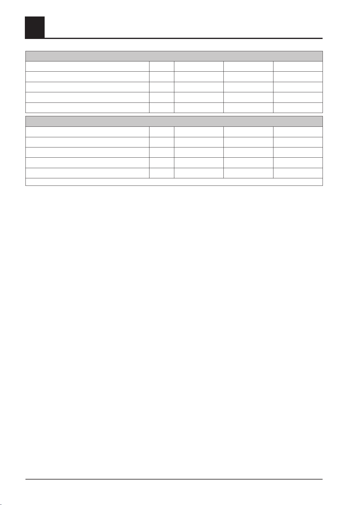
Test data pellets - Emissions in [mg/MJ] (RL / PL)
Carbon monoxide (CO) mg/MJ 5 / 16 5 / 11 4 / 6
Nitrogen oxide (NOx) mg/MJ 64 / 57 67 / 57 70 / 58
Organic hydrocarbons (OGC) mg/MJ <1 / <1 <2 / <2 <2 / <2
Dust mg/MJ 24 / 14 18 / 12 11 / 9
Boiler efficiency % 90,8 / 93,4 92,1 / 92,7 93,5 / 92,0
Test data pellets - Emissions in [mg/m³]1) (RL / PL)
Carbon monoxide (CO) mg/m³ 8 / 23 7 / 16 6 / 8
Nitrogen oxide (NOx) mg/m³ 94 / 84 98 / 85 103 / 86
Organic hydrocarbons (OGC) mg/m³ <1 / <1 <2 / <2 <2 / <2
Dust mg/m³ 35 / 21 25 / 17 15 / 13
Boiler efficiency % 90,8 / 93,4 92,1 / 92,7 93,5 / 92,0
1.Emissions values are based on dry flue gas at standard temperature and pressure (0°C, 1013 mbar) with a volume content of oxygen of 13%
Technical specifications
14 Froling GesmbH | A-4710 Grieskirchen, Industriestraße 12 | www.froling.com
Page 15

Assembly
Transport
4 Assembly
4.1 Transport
4
NOTICE
Damage to components if handled incorrectly
❒ Follow the transport instructions on the packaging
❒ Transport components with care to avoid damage
❒ Protect the packaging against damp
❒ Operate unloading, positioning and mounting only by trained professionals!
Staff has to be familiar with the handling and moving of heavy loads! (tools
and lifting tools , lashing points, etc.)
4.2 Positioning
❒ Attach a cable winch or similar lifting device to the eyelets on the boiler
4.3 Temporary storage
If the system is to be assembled at a later stage:
Store components at a protected location, which is dry and free from dust
❒
➥ Damp and frost can damage components, particularly electric ones!
4.4 Set-up in the boiler room
4.4.1 Moving the boiler in the boiler room
❒ Position a fork-lift or similar lifting device with a suitable load-bearing capacity at
the base frame
Lift and transport to the intended position in the installation room
❒
➥ Observe the minimum distances in the boiler room.
Installation Instructions TX 150-250 | M1320112_en 15
Page 16
Assembly
4
Set-up in the boiler room
4.4.2 Minimum distances in the boiler room
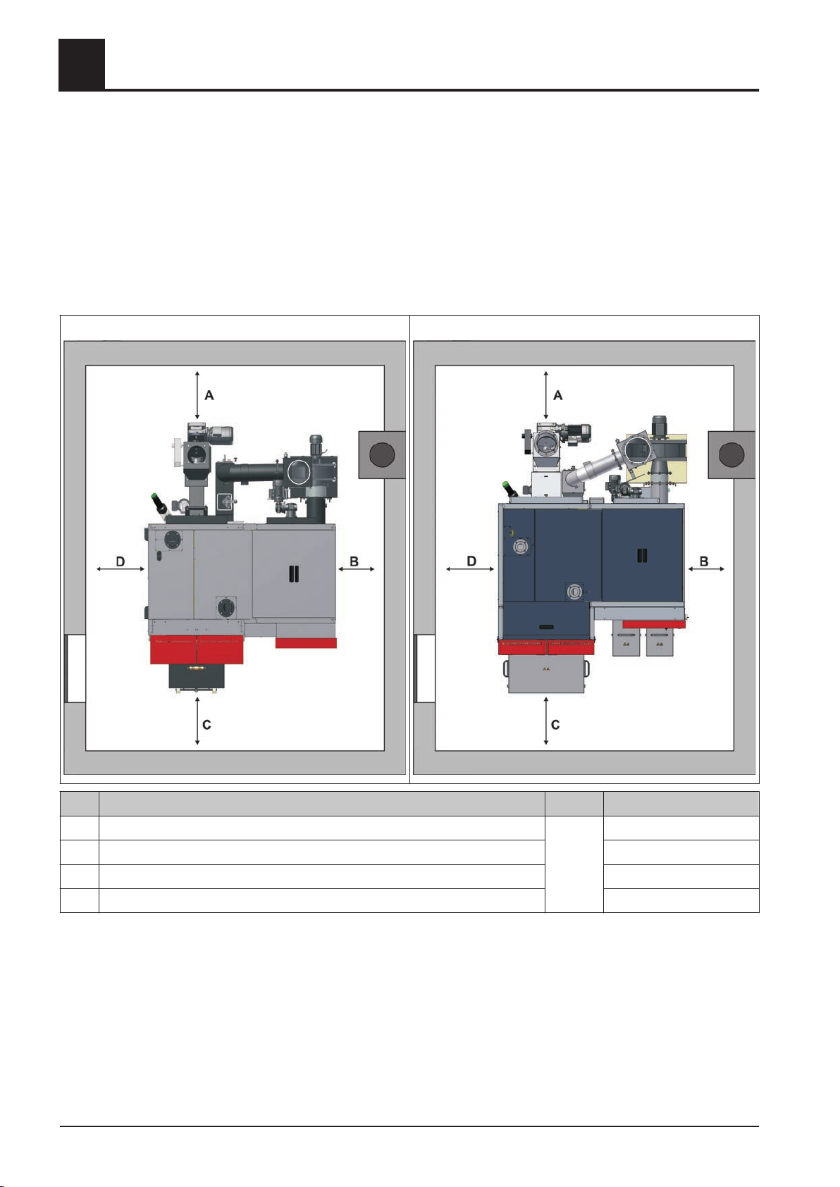
▪ The system should generally be set up so that it is accessible from all sides allow‐
ing quick and easy maintenance.
Regional regulations regarding necessary maintenance areas for inspecting the
▪
chimney should be observed in addition to the specified minimum distances!
▪ Observe the applicable standards and regulations when setting up the system.
▪ Observe additional standards for noise protection
(ÖNORM H 5190 - Noise protection measures)
TX 150:
TX 200/250:
Pos. Description Unit TX 150/200/250
A Space requirement for inspection area of infeed mm
B Distance from heat exchanger side to wall 300 (12)
C Space requirement for removal of ash box 400 (16)
D Space requirement for inspection area of retort 400 (16)
16 Froling GesmbH | A-4710 Grieskirchen, Industriestraße 12 | www.froling.com
(inch)
400 (16)
Page 17
Assembly
Mounting steps
4.5 Mounting steps
4.5.1 General information
4
Boiler front side and boiler back side
The front side is considered as operator side of the boiler. All for operation necessary
elements like combustion chamber door, ash box and control box are arranged on the
front side. The back side is the opposite side. On the back side the stoker unit, the
WOS-drive as well as the whole exhaust gas routing system are arranged.
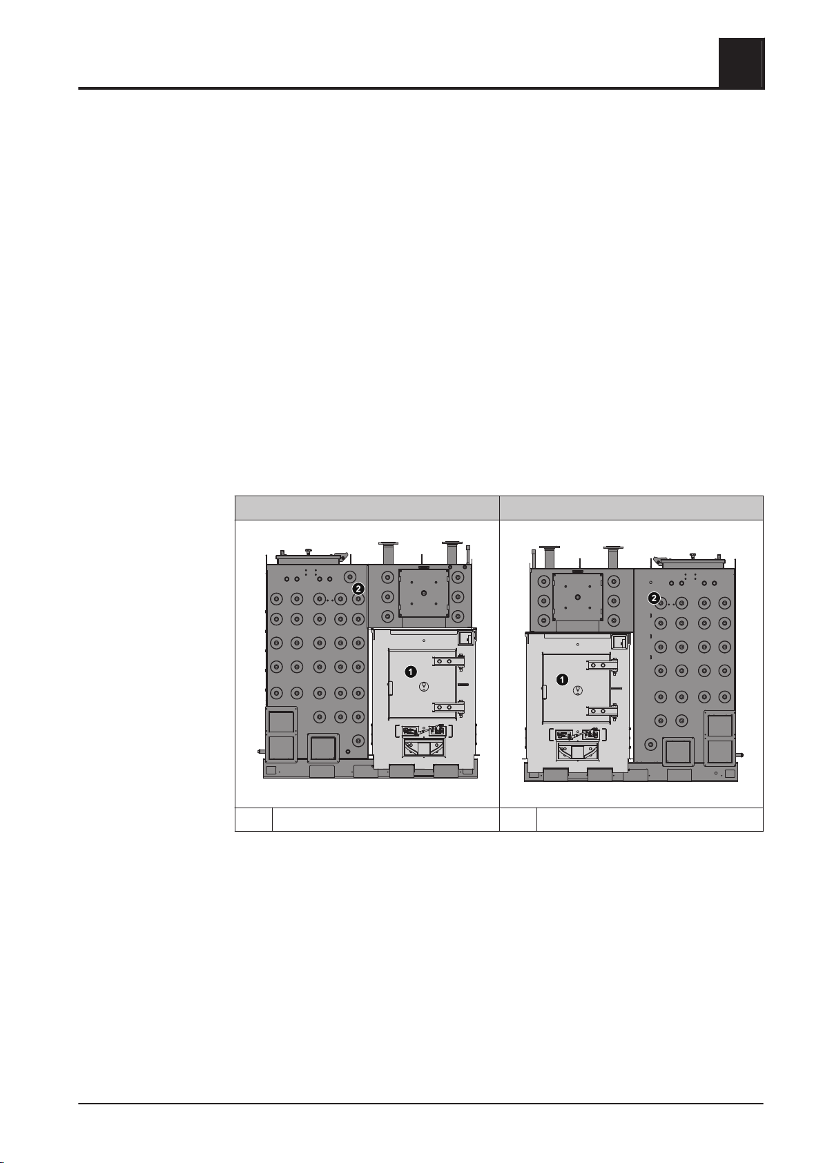
Heat exchanger left or right
In general it is different, if the heat exchanger of the TX (front view = operator side) is
positioned on the left or the right side of the fire box. Before mounting it has to be de‐
fined, whether the heat exchanger is mounted on the left or the right, as far as it is not
defined by an existing floor plan.
Heat exchanger left Heat exchanger right
1 Fire box 2 Heat exchanger
The following illustrations of mounting steps show the heat exchanger on the right
side. If the heat exchanger is arranged on the left side, the mounting steps have to be
applied laterally reversed by analogy.
Installation Instructions TX 150-250 | M1320112_en 17
Page 18
Assembly
4
Mounting steps
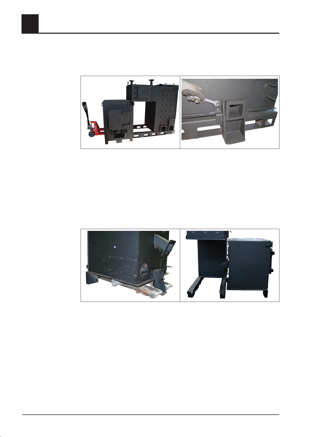
4.5.2 Screwing the fire box with the heat exchanger
Positioning of the fire box from the side
❒ Insert the lift truck at the fire box opposite and lift it up as far as the fire box can be
positioned without colliding with the heat exchanger
❒
Bring in the fire box completely at the side of the heat exchanger and lower it slow‐
ly
❒ Remove the supporting post on the ash flange of the fire box
Positioning the fire box from the front
If there is not enough space to bring in the fire box from the side, it is possible to bring
it in from the front:
❒ Insert the lift truck at the fire box opposite the supporting post
Place a piece of pipe, square timber or similar with a height of approx. 75 mm be‐
❒
low the fire box as a distance piece
❒ Lift the fire box with the lifting truck and remove the supporting post on the ash
flange
❒ Position the loading arm of the lift truck by the openings of the main frame und in‐
sert the fire box as far as the distance piece can be positioned within the apron
❒ Lower the fire box, position the distance piece within the apron, lift the fire box
once again and bring it completely in.
18 Froling GesmbH | A-4710 Grieskirchen, Industriestraße 12 | www.froling.com
Page 19
Assembly
Mounting steps
4
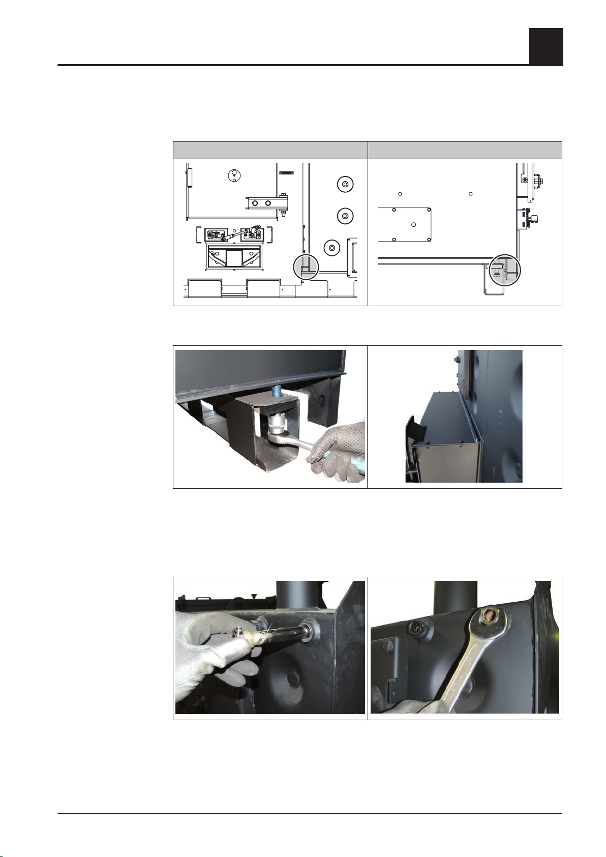
Adjust and fix the fire box
Before fixing, the fire box has to be adjusted in the heat exchanger. Two arrestors
have to be attended.
Arrestor - Heat exchanger Arrestor - Main frame
After positioning of the fire box in the heat exchanger:
❒ Tighten the fire box against the heat exchanger with carrying bolts through the lat‐
eral cutouts in the main frame
➥ Check that the fire box is aligned with the heat exchanger and pay attention on
seal cord, it shall have a constant closing!
4.5.3 Installing sensor of thermal discharge system
❒ Remove blind plug at the heat exchanger
❒
Use both thread tape and pipe dope and screw in thermowell
Installation Instructions TX 150-250 | M1320112_en 19
Page 20
Assembly
4
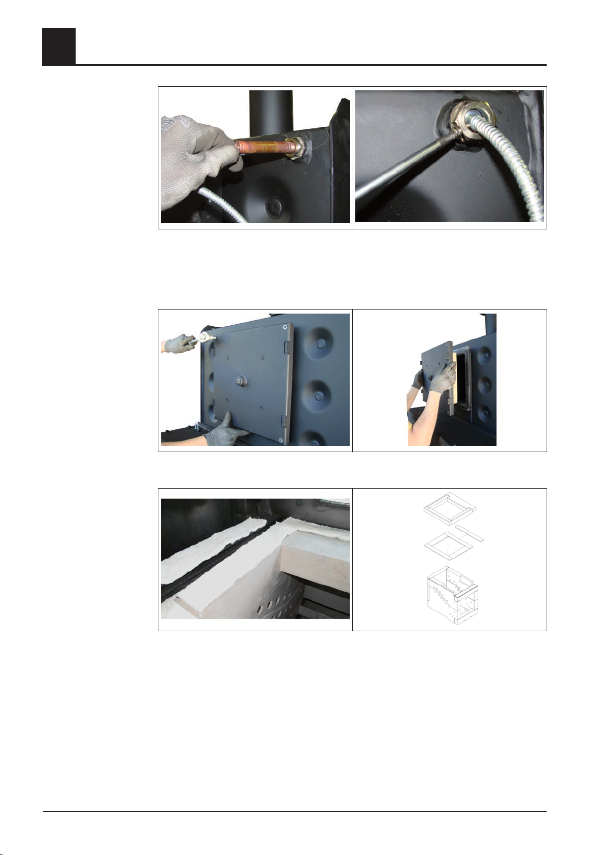
❒ Insert sensor of the thermal discharge system at thermowell
Insert protective tube of the sensor and tighten the fixing screw gently
❒
Mounting steps
4.5.4 Assembly of fireclay blocks
❒ Remove bolting on the heat exchanger cover
Remove the heat exchanger cover
❒
❒ Place ceramic fibre mats on the fire box as shown
➥ Make sure that two mats are placed on the side to the heat exchanger
Place fireclay blocks on the ceramic fibre mats as shown
❒
➥ Place the lateral capstone on the side to the heat exchanger with the grade
downwards
20 Froling GesmbH | A-4710 Grieskirchen, Industriestraße 12 | www.froling.com
Page 21
Assembly
Mounting steps
4.5.5 Preparation of flue gas recirculation connection (Option)
4
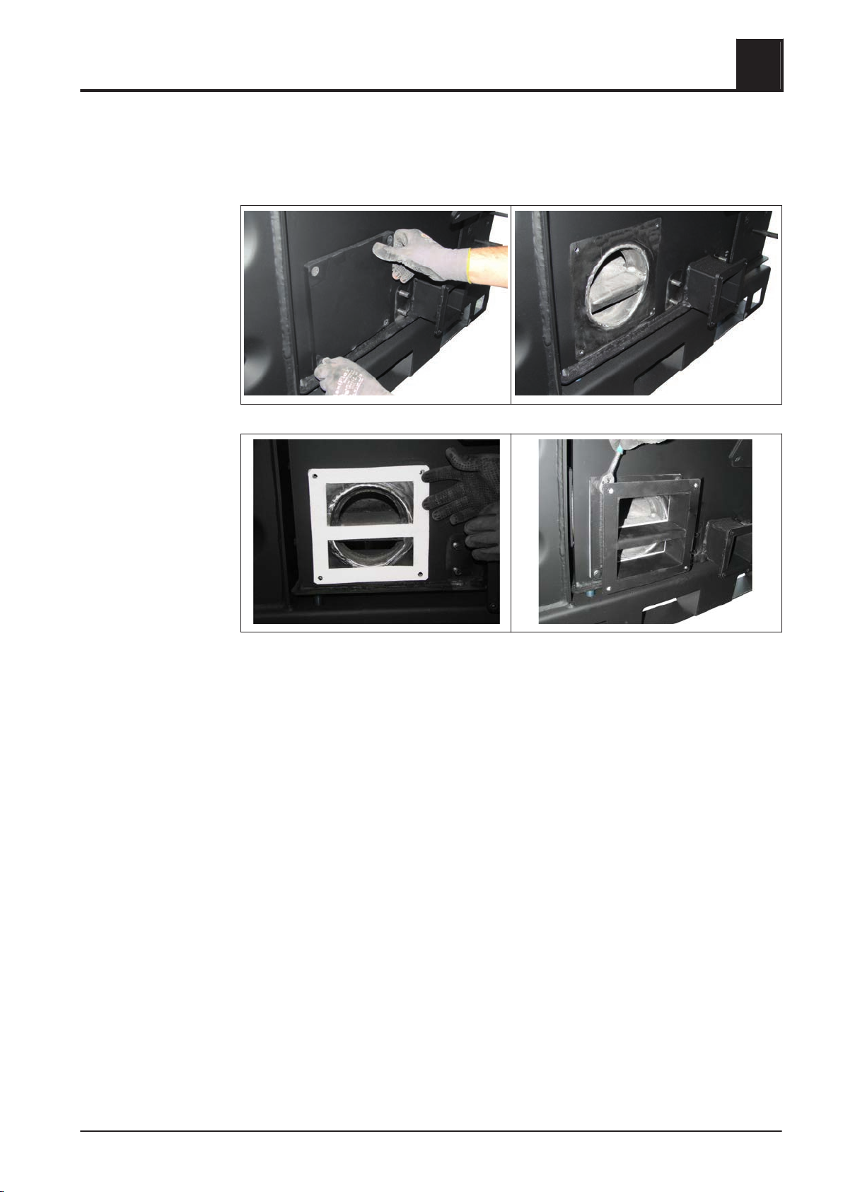
In case of configuration of the boiler with optional flue gas recirculation (FGR), the fol‐
lowing preparation work has to be carried out:
❒ Remove the blanking plate on the fire box on the left by the infeed unit
❒ Fix the inter-flange for flue gas recirculation connection along with seal on the boil‐
er. Take the previously dismounted screws.
➥ The central c-profile in the inter-flange has to point downwards to the boiler.
➥ Press nuts have to be at the outer flange
Installation Instructions TX 150-250 | M1320112_en 21
Page 22
Assembly
4
Mounting steps
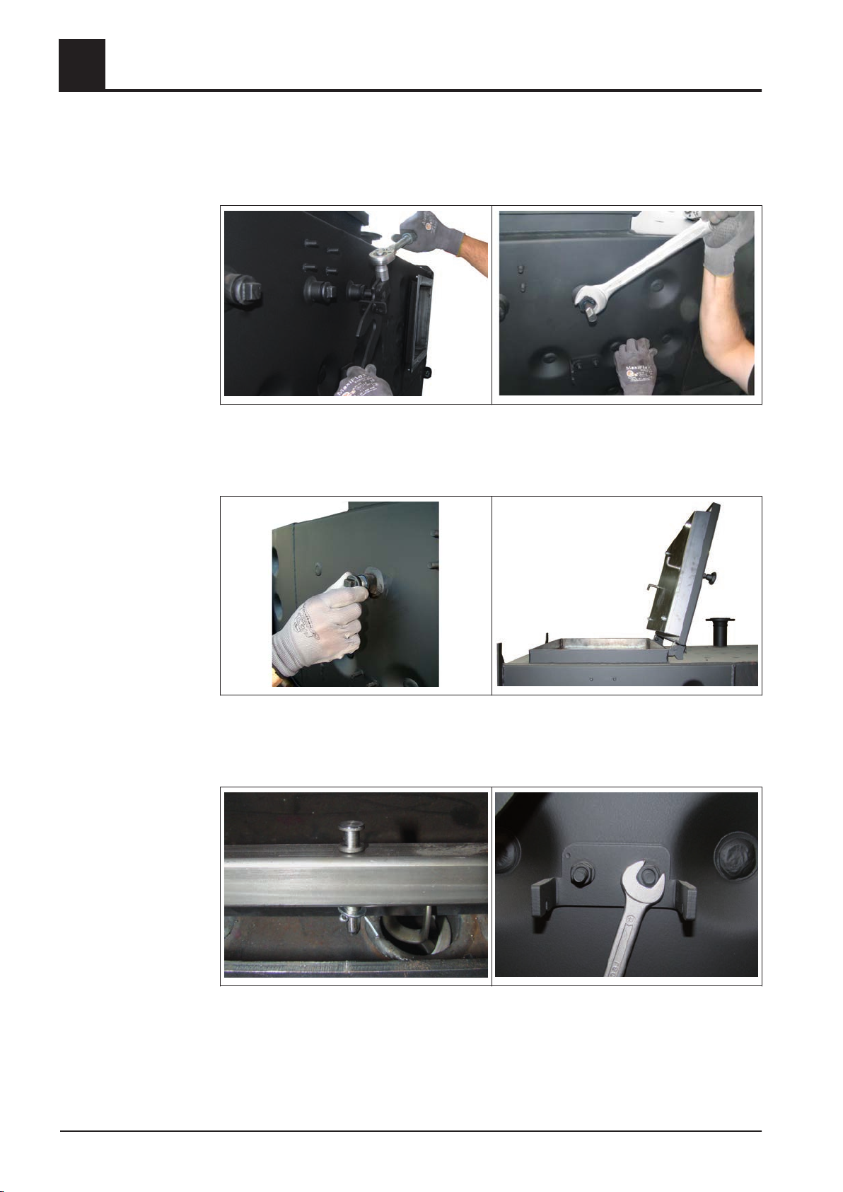
4.5.6 Retrofitting the WOS bar (if necessary)
The WOS drive is always mounted on the back side of the boiler opposite to the con‐
trol box. Depending on delivery condition the WOS bar has to be adjusted accordingly:
❒ Loosen the clamping jaw at the actuating lever and remove them from the WOS
shaft
❒
Unscrew the bearing bush of the shaft
❒ Remove the blind plug on the opposite of the WOS shaft
Loosen the screwing on the heat exchanger cover, set star grip to left-hand stop
❒
and open the cover
❒
Remove safety pin of the WOS shaft and pull out the shaft
❒ Fit in the WOS shaft from the opposite and pull it through
❒ Remount the prior removed bearing bush and blind plug on the opposite side
❒ Remove the tension hook and remount it on the opposite as well
22 Froling GesmbH | A-4710 Grieskirchen, Industriestraße 12 | www.froling.com
Page 23
Assembly
Mounting steps
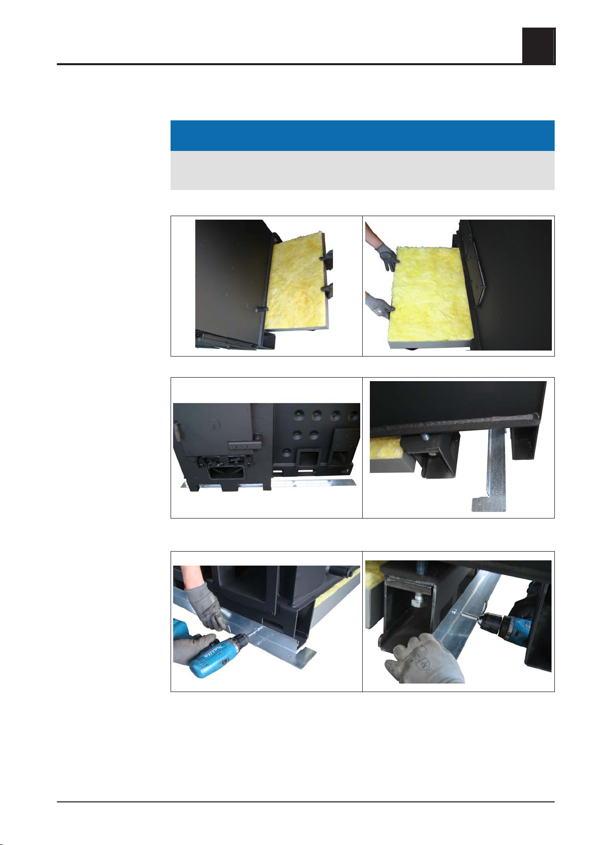
4.5.7 Installing lower main frame of insulation
4
NOTICE
Separate parts of the boiler are fitted with a protective film. This MUST be re‐
moved before assemby!
❒ Insert each bottom insulation below fire box and heat exchanger
❒ Place longitudinal and cross elements of the bottom main frame of the insulation
on the floor
❒ Fix longitudinal elements at intended positions on the front and the back of the
boiler
Installation Instructions TX 150-250 | M1320112_en 23
Page 24
Assembly
4
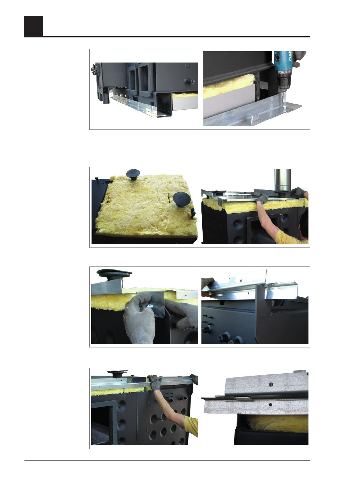
❒ Place cross elements on longitudinal elements and bolt it together at the angles
Mounting steps
4.5.8 Installing upper main frame of insulation
❒ Place the heat insulation mat as shown on the boiler and position the cable routing
above
❒ Screw the cable routing to the boiler laterally
❒
Place longitudinal elements on the front and the back of the boiler
❒ When putting on make sure that the lug of the cable routing threads into the frame
24 Froling GesmbH | A-4710 Grieskirchen, Industriestraße 12 | www.froling.com
Page 25
Assembly
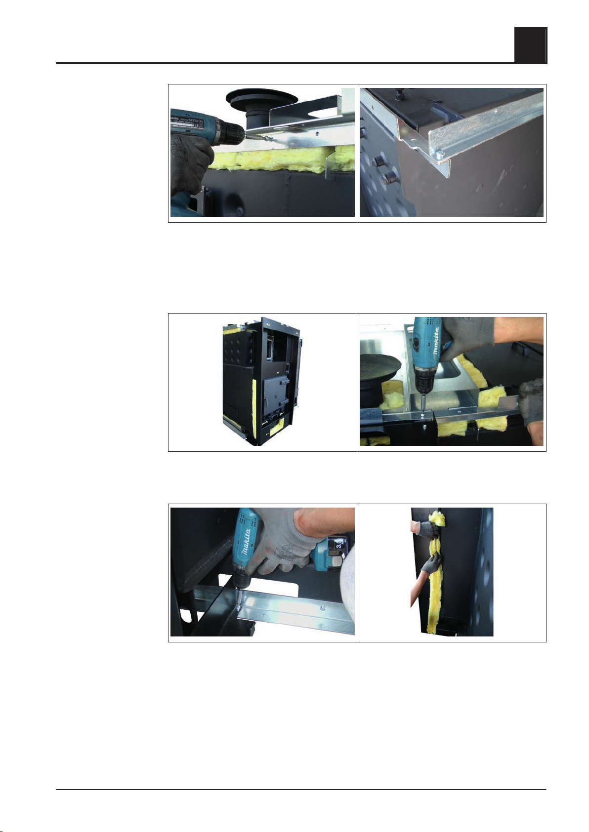
Mounting steps
4.5.9 Installing the frame for the insulating door
❒ Fix longitudinal elements to the boiler laterally
❒
At the heat exchanger side, place cross elements on longitudinal elements and
bolt it together at the corners
4
❒ Place frame element for insulating door on the front
❒
Screw the frame element together with the upper and lower longitudinal element
❒ Insert insulation on the left and the right of the combustion chamber door
Installation Instructions TX 150-250 | M1320112_en 25
Page 26
Assembly
4
Mounting steps
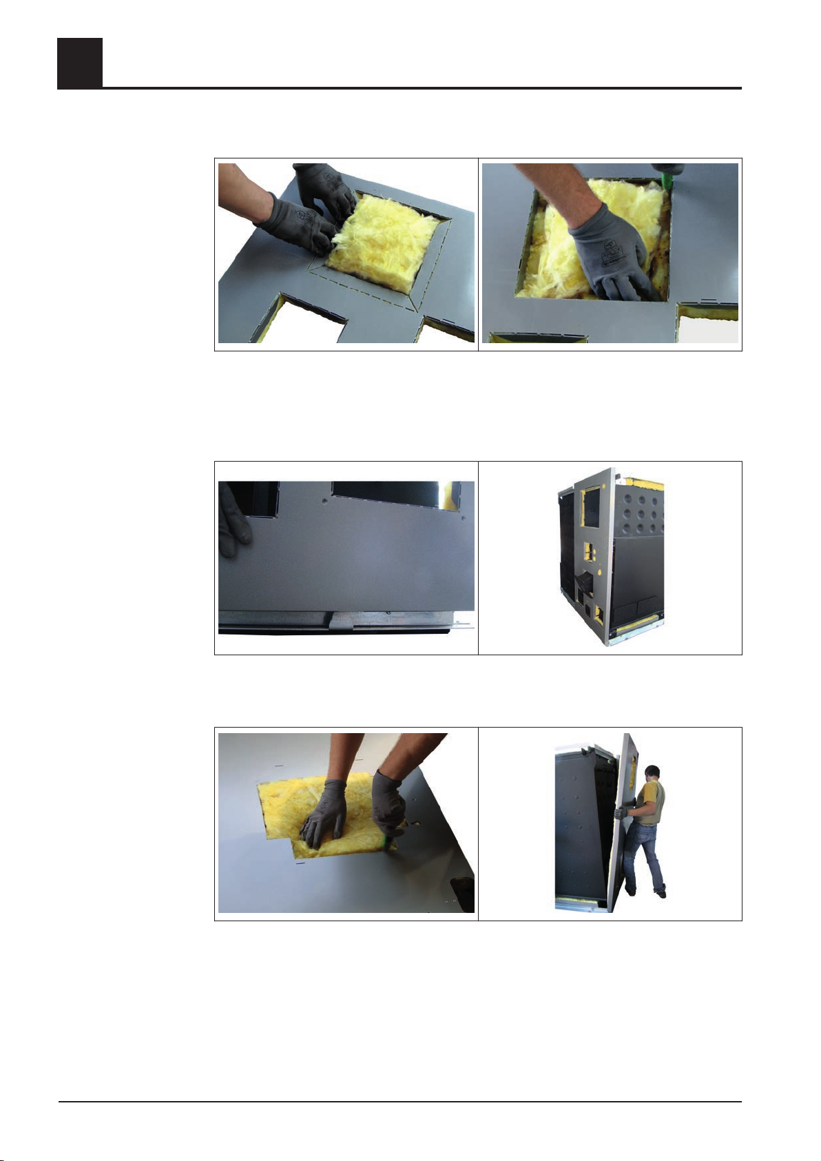
4.5.10 Installing the insulating side panels
❒ When applying the optional FGR separate the pre-cut recess at the back insulat‐
ing side panel of the retort
❒
Bend the lugs of the pre-cut recess at right angles inwards
❒ Cut the insulation with a cutter along the edge and remove it
❒ Suspend the back insulating side panel at the upper and lower frame elements
➥ Ensure correct threading into the lugs of the lower longitudinal element
❒ Separate the pre-cut recess for the WOS drive at the back insulating side panel of
the heat exchanger
Cut the underlying insulation with a cutter along the edge and remove it
❒
❒ Suspend the back insulating side panel for the heat exchanger at the upper and
lower frame elements
26 Froling GesmbH | A-4710 Grieskirchen, Industriestraße 12 | www.froling.com
Page 27
Assembly
Mounting steps
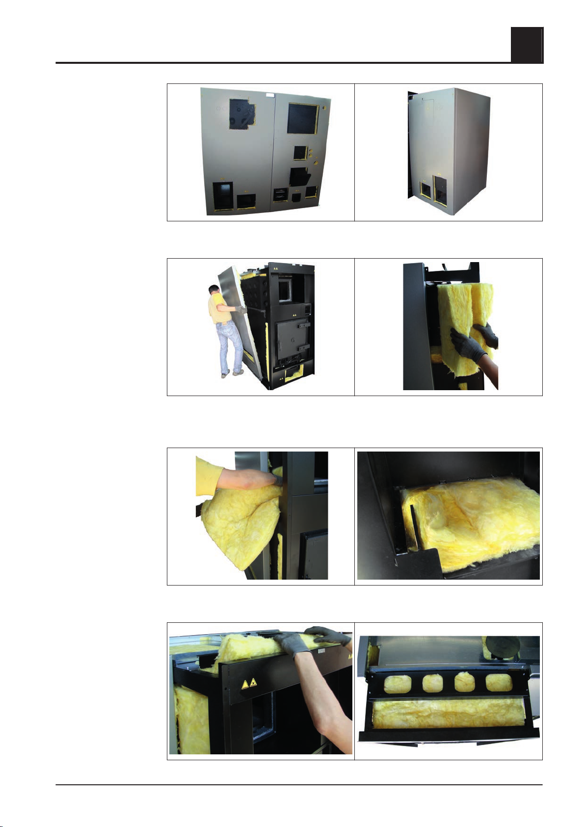
4
❒ Suspend the front and lateral insulating side panel of the heat exchanger
❒ Suspend the opposite lateral insulating side panel
❒
Coat spaces with heat insulation mats lateral of the heat exchanger cover
❒ TX 250: Mount an additional insulation mat at the frame above the fire box
❒ Place the heat insulation mat at the upper range of the frame
Installation Instructions TX 150-250 | M1320112_en 27
Page 28
4
Assembly
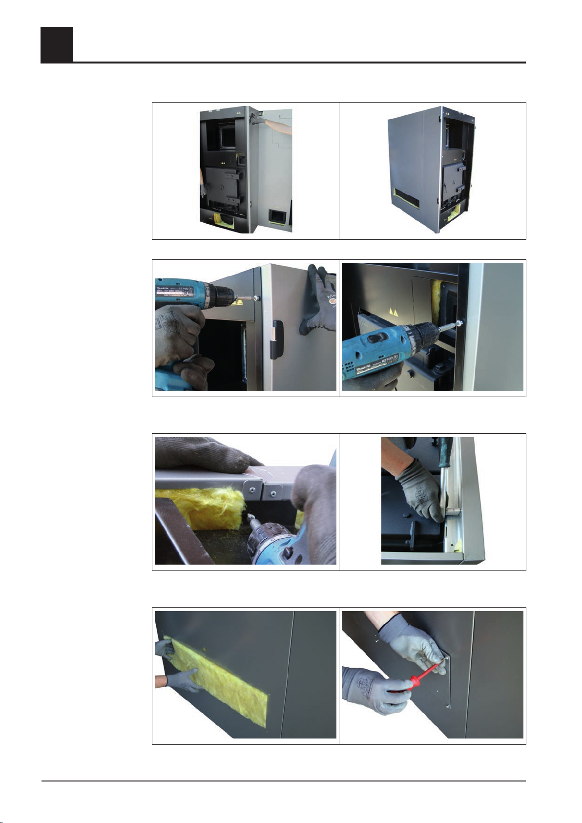
Mounting steps
❒ Position the lateral insulating side panels with door hinge left and right at the frame
❒ Fix the side panels at the frame using 4 thread forming screws
❒ Screw all insulating side panels with elements of the main frame together
❒ Cover the inspection opening of the retort with insulation
Mount inspection cover at the insulating side panel
❒
28 Froling GesmbH | A-4710 Grieskirchen, Industriestraße 12 | www.froling.com
Page 29
Assembly
Mounting steps
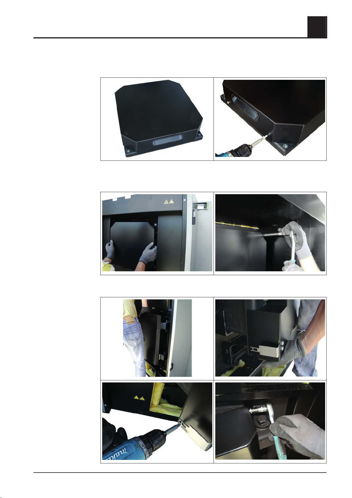
4.5.11 Complete the heat exchanger cover and the combustion chamber door
❒ Position the cover plate at the heat exchanger cover
❒
Fix the cover plate using 4 thread forming screws
4
❒ Mount the heat exchanger cover at the heat exchanger
Installation Instructions TX 150-250 | M1320112_en 29
Page 30
4
Assembly
Mounting steps
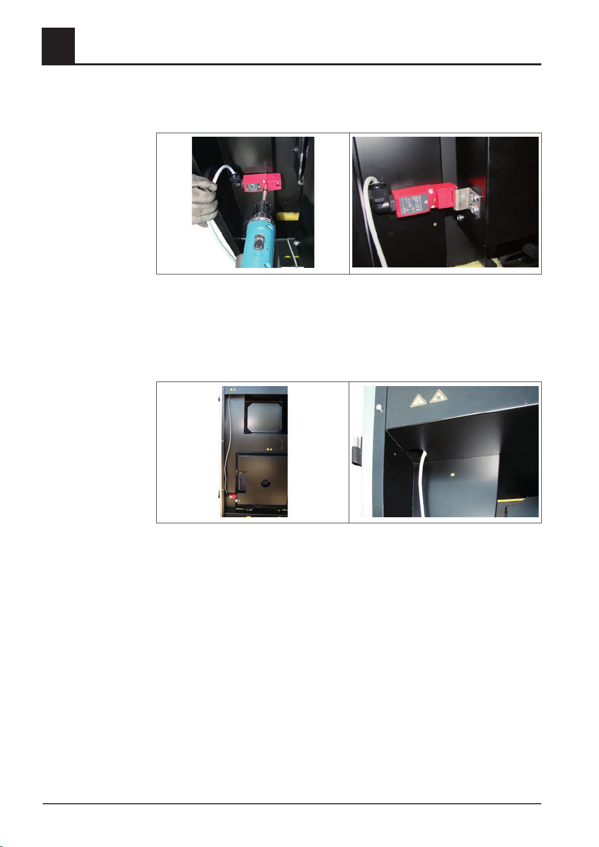
❒ Position the cover plate at the combustion chamber door and fix it on the left and
on the right with thread forming screws
❒ Mount safety limit switch at the frame element
Loosen screwings at the key plate
❒
❒ Close the combustion chamber door and adjust the key plate so that an unproble‐
matic locking at the safety limit switch is possible
❒ Fix the positioning of the key plate and check the correct locking at the limit switch
when opening and closing the combustion chamber door for several times
❒ Lay the connection cable of the safety limit switch upwards through the upper
opening of the frame element
30 Froling GesmbH | A-4710 Grieskirchen, Industriestraße 12 | www.froling.com
Page 31
Assembly
Mounting steps
4.5.12 Check grate settings and install the tipping grate motor
4
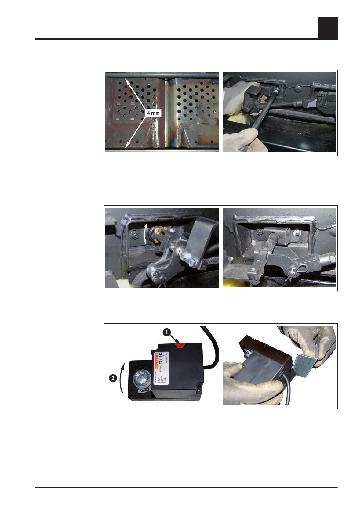
❒ Open the combustion chamber door and check front and rear separation in the fire
box
➥ Min. separation: 4mm (0.16 inch)!
For corrections of the grate settings dismount the safety plate at the grate shaft
❒
❒ Position the grate by screwing the shaft bearing
Fix the position of the shaft bearing by mounting the safety plate
❒
❒ Bring grate to closed position
❒
Press the release knob at the actuator and set the shaft support to the right-hand
stop while pressing the release knob
❒ Mount the torque arm at the actuator
Installation Instructions TX 150-250 | M1320112_en 31
Page 32
4
Assembly
Mounting steps
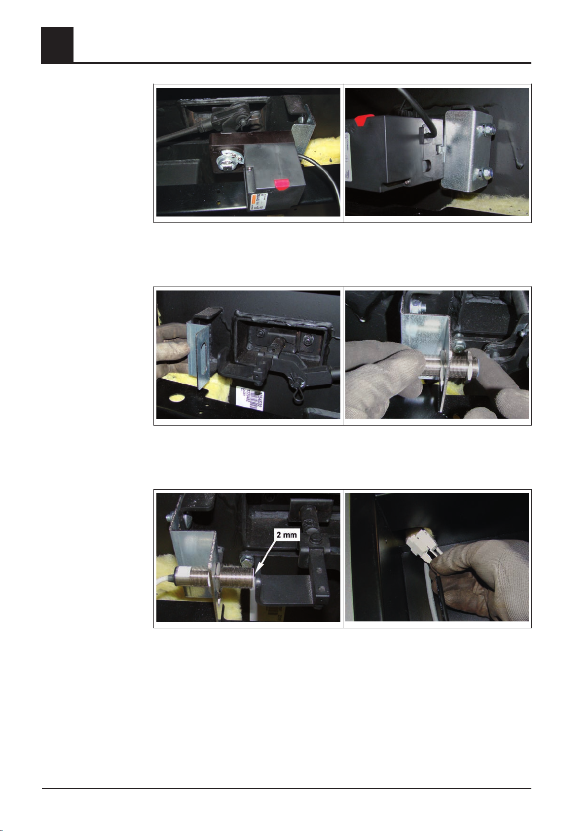
❒ Put the actuator together with the torque arm on the right grate shaft
Fix the torque arm with 2 round-head screws M8x20, lining disks M8 and lock nuts
❒
M8 at the fire box
❒ Fix the sensor mounting at the side of the left grate shaft with 2 round-head
screws M8x20, lining disks M8 and lock nuts M8 at the fire box
❒
Thread the proximity sensor at the mounting and fix it easily with pre-installed nuts
❒ Fix the sensor with approx. 1-2 mm (0.04-0.08 inch) separation
Lay the connection cable of the sensor and the actuator on the left side upwards
❒
and lead it through the upper opening at the frame element
32 Froling GesmbH | A-4710 Grieskirchen, Industriestraße 12 | www.froling.com
Page 33
Assembly
Mounting steps
4.5.13 Installing the fire box ash removal unit
4
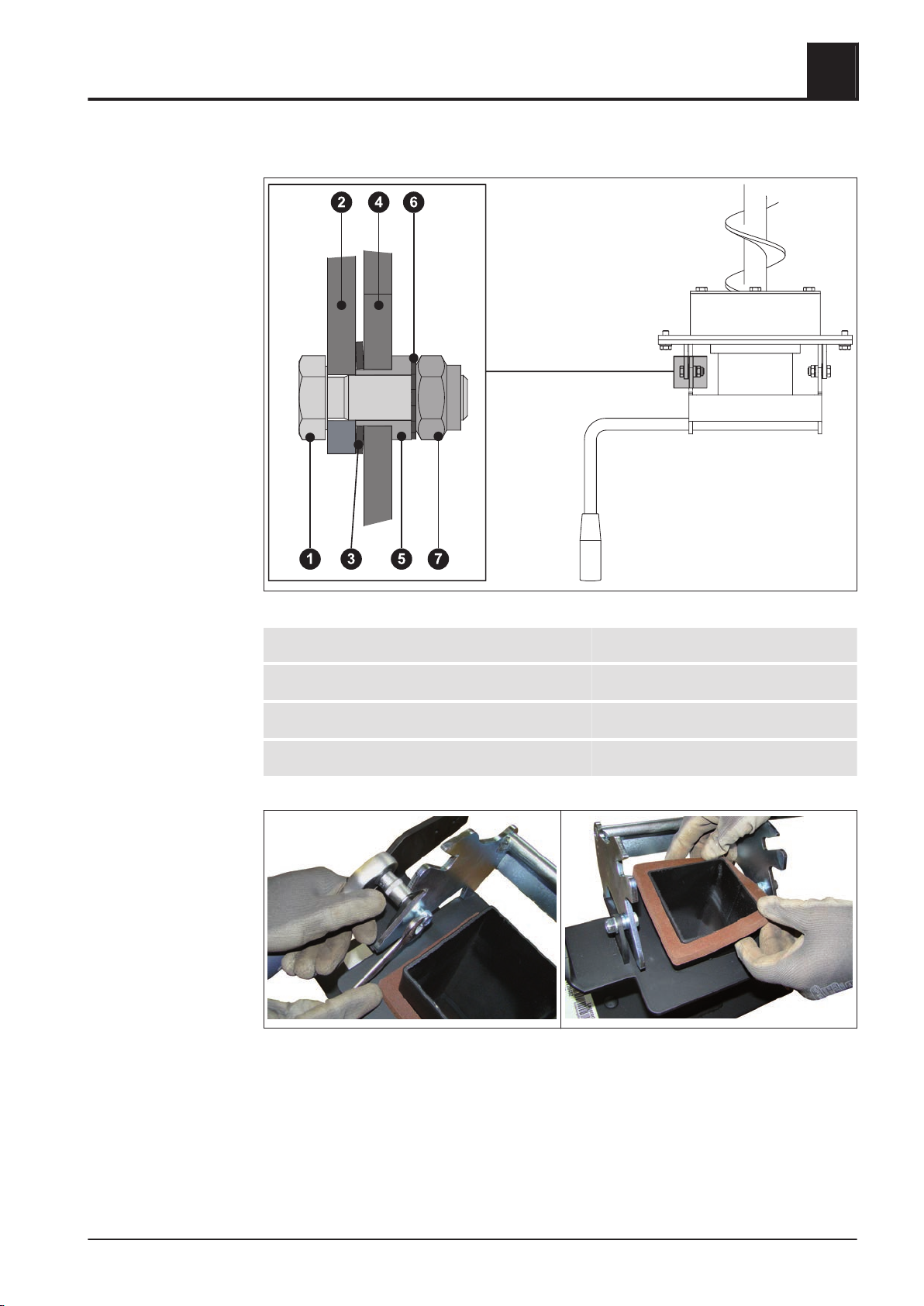
1 Hexagonal bolt M8x25 2 Ash removal flange
3 Plate washer 4 Locking lever
5 Bearing bush 6 Chopper disk M8
7 Lock nut M8
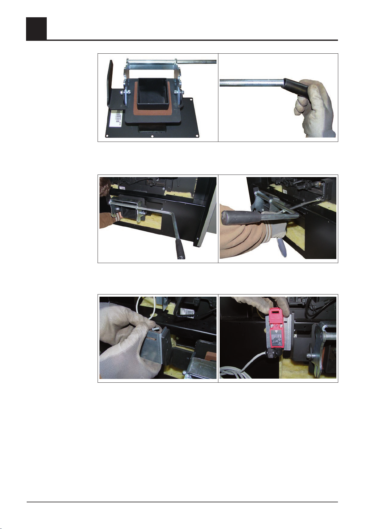
❒ Mount the locking lever at the ash removal flange as seen in the illustration above
❒
Put the rubber seal over the channel of the ash removal flange
Installation Instructions TX 150-250 | M1320112_en 33
Page 34
4
Assembly
Mounting steps
❒ Put the plastic handle on the locking lever
➥ Use a rubber mallet
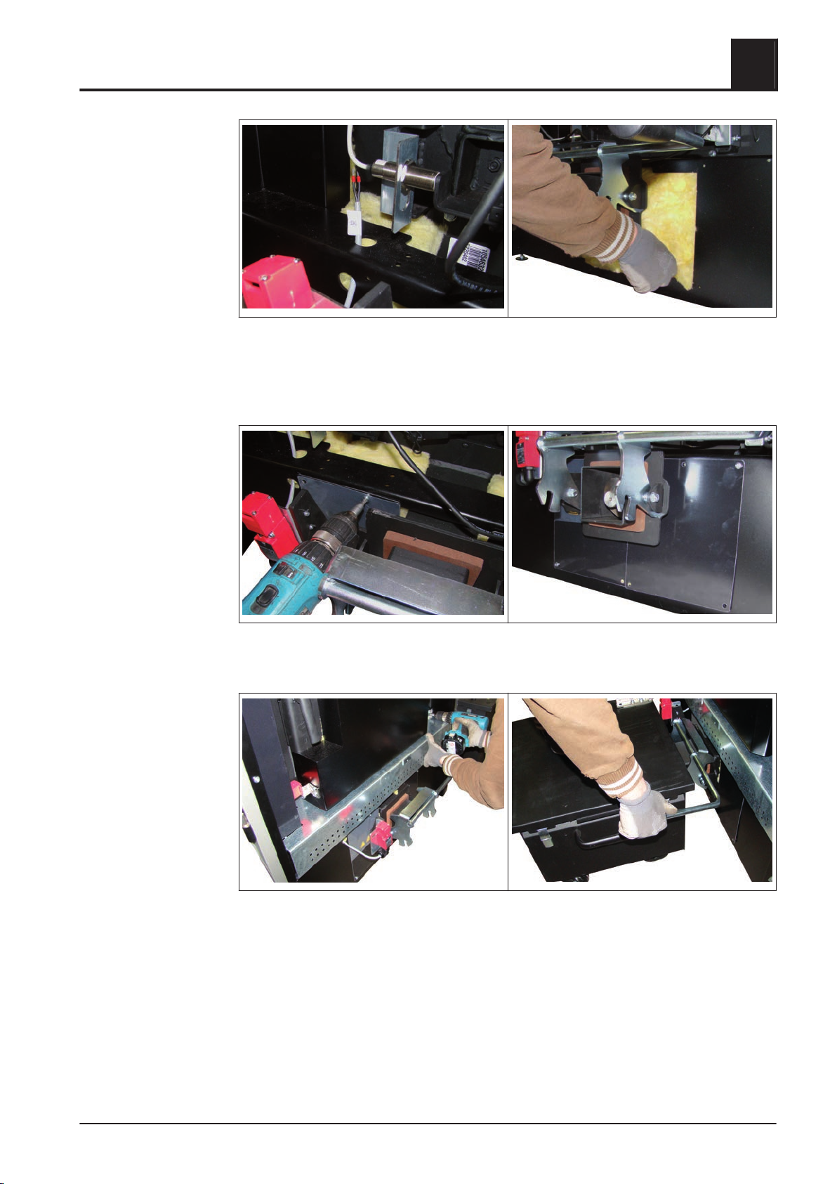
❒ Slip the assembled ash removal flange on the fire box and fix it with 6 hexagon
bolts M8x25 and lining disks M8
❒ Mount the angle plate with 2 thread forming screws at the lug of the ash removal
flange
Mount the safety limit switch with each 2 fillisters M4x30, lining disks M4 and hex‐
❒
agonal nuts M4
➥ Do not fasten screwing yet
34 Froling GesmbH | A-4710 Grieskirchen, Industriestraße 12 | www.froling.com
Page 35
Assembly
Mounting steps
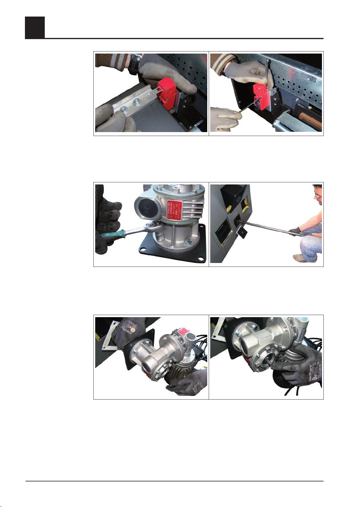
❒ Thread the cable of the safety limit switch through both cuttings at the frame ele‐
ment, lay them on the left side upwards and thread them through at the upper
opening of the frame element
Put two heat insulation mats on the ash flange
❒
4
❒ Fix the cover plates on the left and the right of the ash removal flange with thread
forming screws
❒ Insert the protection plate above the leverage of the tipping device and fix it with
thread forming screws at the fire box
Put the ash box onto the ash removal flange and lock it
❒
Installation Instructions TX 150-250 | M1320112_en 35
Page 36
4
Assembly
Mounting steps
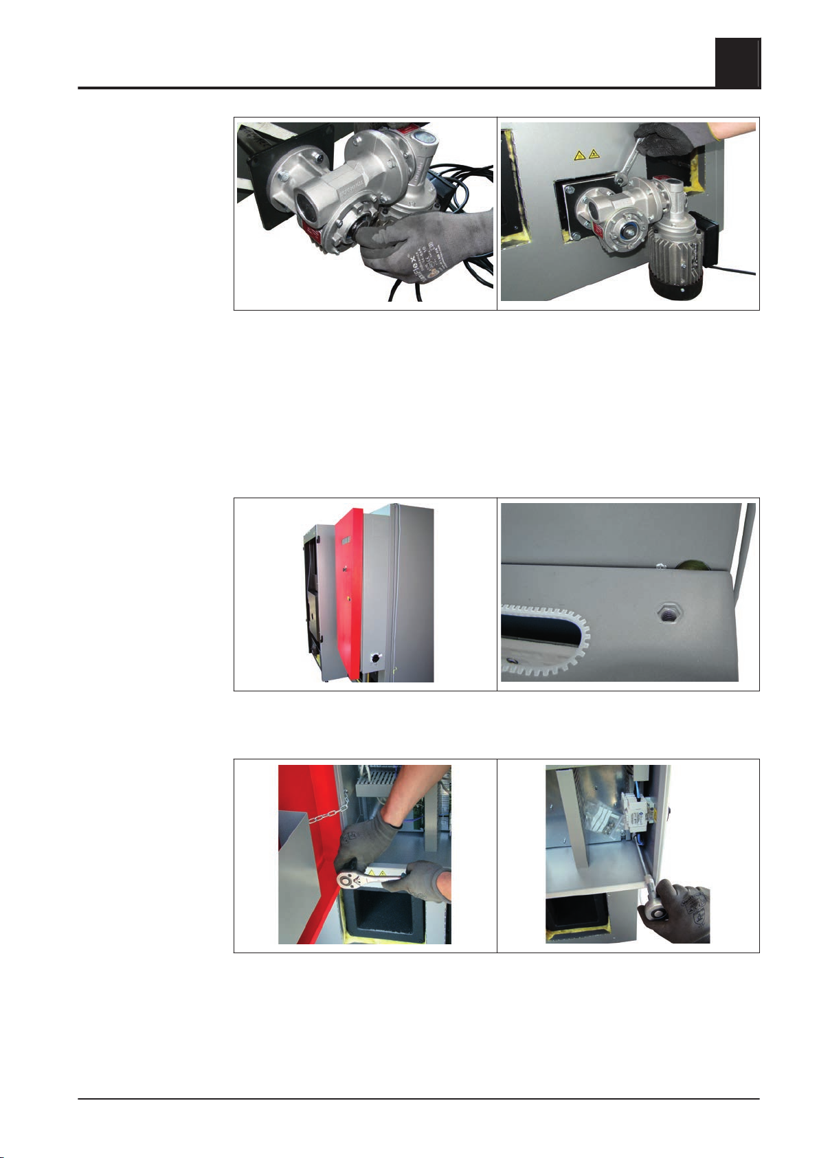
❒ Place the safety limit switch so that the key plate can easily be threaded to the
switch
Fix the position of the safety limit switch by fastening the screwings at the angle
❒
plat and limit switch
❒ Mount the gear motor with 4 hexagonal bolts on the flange plate
❒
Put the ash screw onto the back side of the boiler
❒ Dismount the shaft circlip (big hexagonal bolt and lining disk) and the key at the
end of the shaft
❒ Put the ceramic fibre seal and the gear motor onto the screw
❒
Slide the shaft entirely into the gear drive and rotate it until the key at the shaft
aligns with the key at the gear drive, afterwards insert the fitting key
36 Froling GesmbH | A-4710 Grieskirchen, Industriestraße 12 | www.froling.com
Page 37
Assembly
Mounting steps
4.5.14 Installing the switch cabinet and cable ducts
4
❒ Screw the previously removed shaft circlip onto the shaft
Push the entire unit in and screw it with 4 hexagonal bolts M8x20 and lining disks
❒
M8 at the flange of the fire box
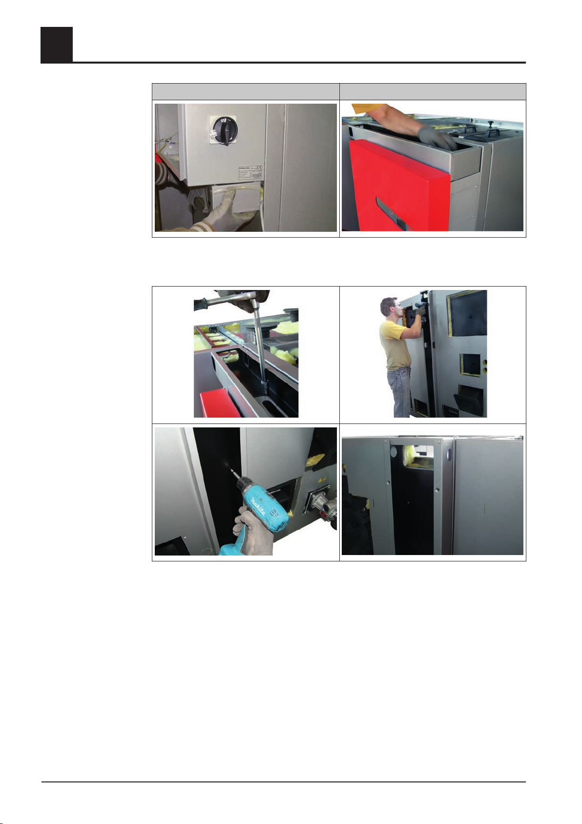
Depending on the design two different sizes of switch cabinets are available (600x600
mm / 600x1200 mm) (24x24 inch / 24x48 inch). The following illustrations show the
bigger switch cabinet (TX200-250 standard delivery contents, TX 150 optional).
❒ Mount the switch cabinet at the heat exchanger front on the insulating side panel
by using the included studs (flat headed screws included to the switch cabinet)
❒ Open the switch cabinet door and fix the switch cabinet at each corner on the in‐
sulating side panel
Installation Instructions TX 150-250 | M1320112_en 37
Page 38
4
Assembly
Mounting steps
Switch cabinet 600x600 mm (24x24 inch) Switch cabinet 600x1200 mm (24x48 inch)
❒ Place the switch cabinet duct below respectively above (depending on the switch
cabinet size)
❒ Fix the switch cabinet duct with hexagonal bolts M8, lining disks M8 and nuts M8
at the switch cabinet
Screw the cable duct on the back with the insulating side panel
❒
➥ Mount cable so that the cable bushing corresponds with the one of the insulat‐
ing side panel
38 Froling GesmbH | A-4710 Grieskirchen, Industriestraße 12 | www.froling.com
Page 39
Assembly
Mounting steps
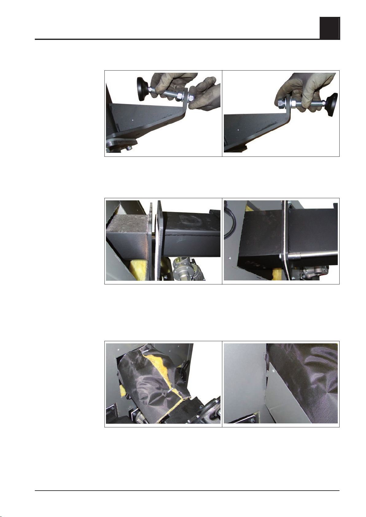
4.5.15 Installing the stoker unit
❒ Remove the pre-installed adjustable foot
Turn round the adjustable foot and remount it
❒
➥ Do not fasten the screwing yet
4
❒ Place the stoker unit at the plug-in flange and lay in the ceramic fibre seal
Screw it with each 4 hexagonal bolts M10x35, washers M10 and hexagonal nuts
❒
M10 to the plug-in flange
❒ Tighten the entire stoker unit incl. adjustable foot and fasten the screwing at the
adjustable foot
❒ Wrap the heat insulation mat around the stoker channel and fix the tension spring
Hook the lower cover plate with the adapter onto the insulating side panel
❒
Installation Instructions TX 150-250 | M1320112_en 39
Page 40
Assembly
4
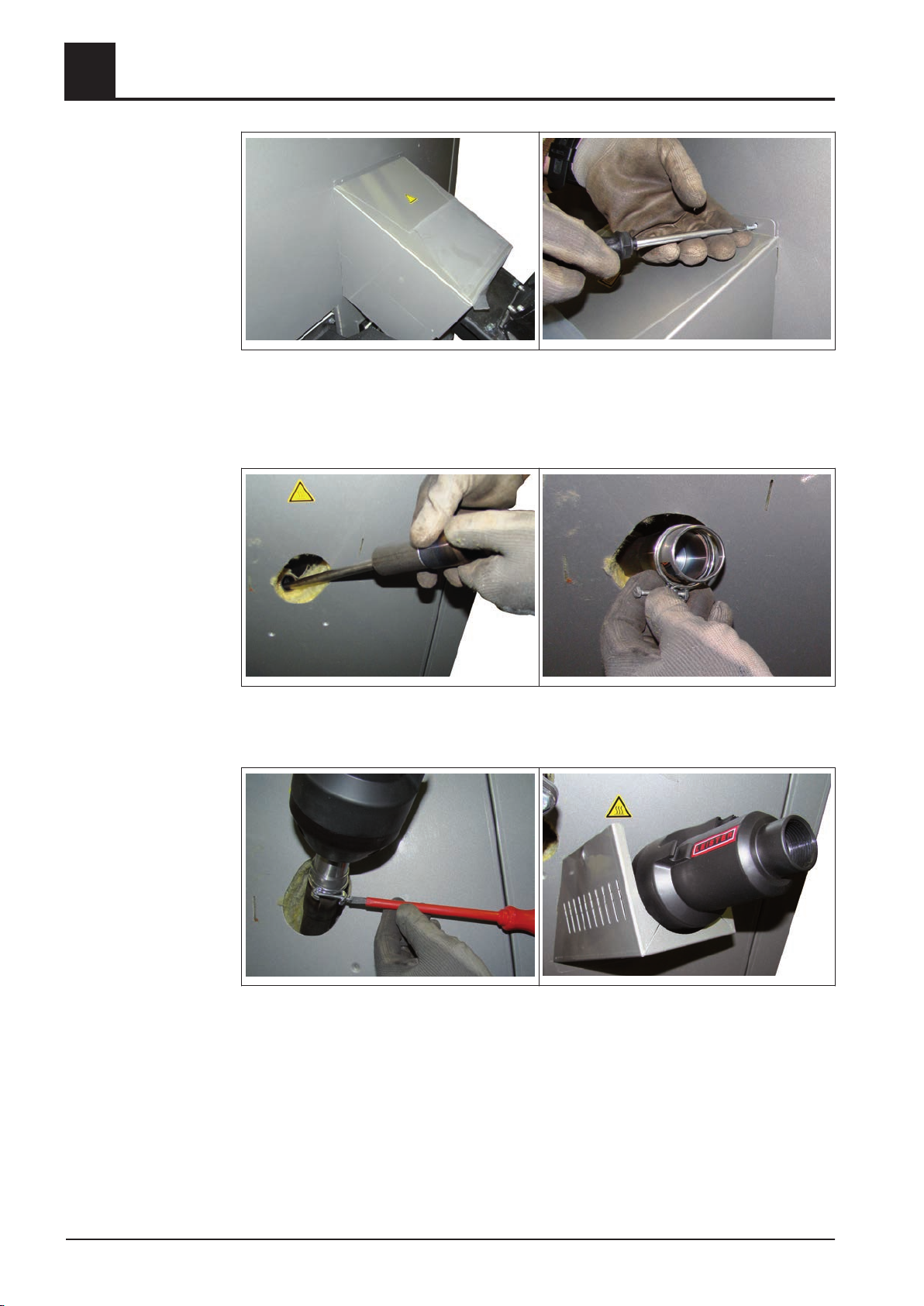
❒ Hook onto the top cover plate and screw it together with the insulating side panel
and the lower cover plate
Mounting steps
4.5.16 Installing the automatic igniter
❒ Screw in the ignitor pipe
Put the double wire spring clamp over the ignitor pipe
❒
❒ Put the ignitor into the ignitor pipe and fix it with a double wire spring clamp
➥ Tighten the clamp gently to avoid damages
Hook the base part of the cover with the adapter onto the insulating side panel
❒
40 Froling GesmbH | A-4710 Grieskirchen, Industriestraße 12 | www.froling.com
Page 41
Assembly
Mounting steps
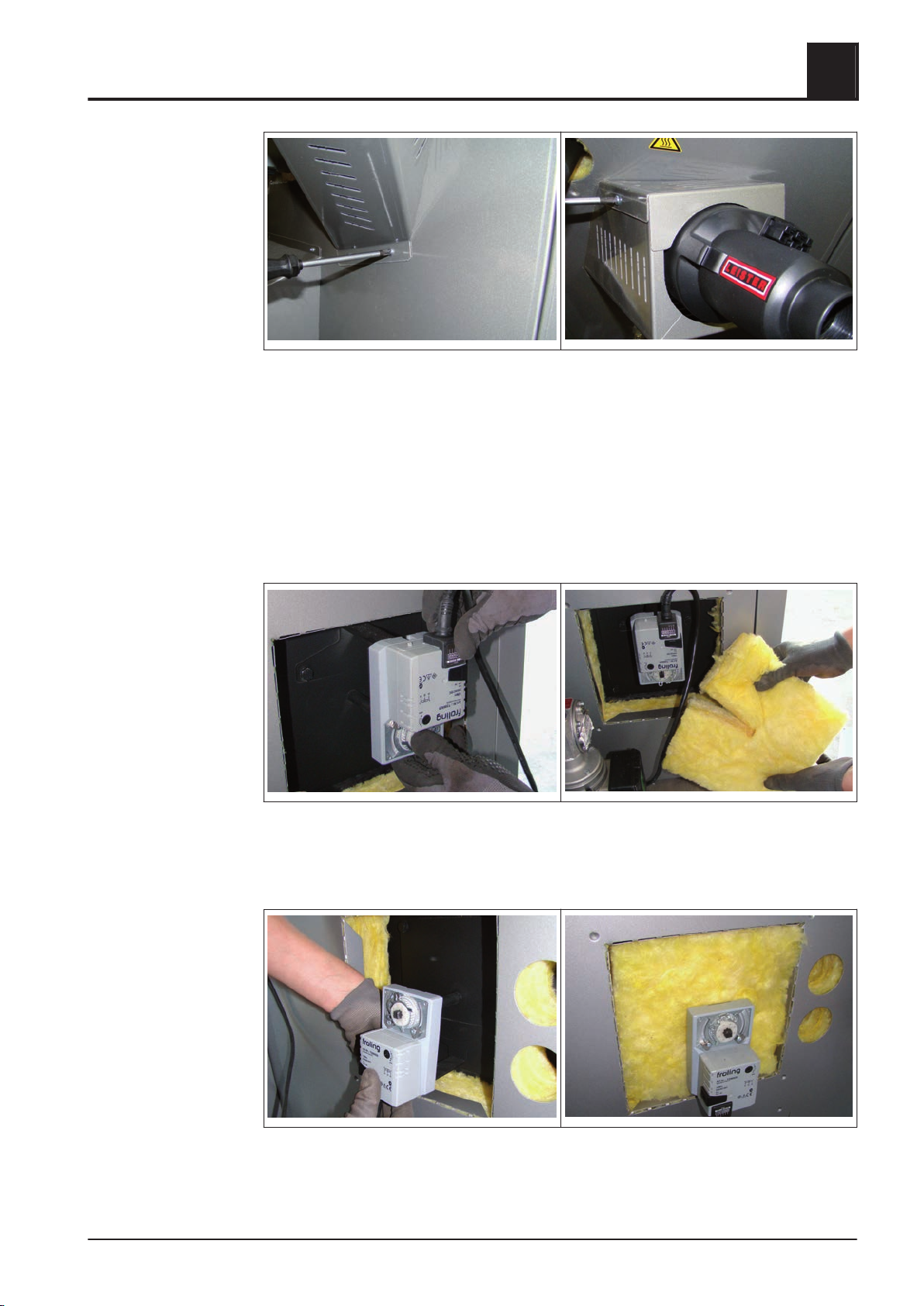
4.5.17 Installing the actuators of the air flaps
❒ Fix the base part of the cover on the underside with sheet metal screws
Put onto the top of the cover and fix it with sheet metal screws at the side of the
❒
base part
Before installing the actuators:
Set air flap with a nipper to left-hand stop
❒
❒ Press the release knob at the actuator and set the shaft support to the left-hand
stop while pressing the release knob
4
❒ Put on the actuator for primary air to the right of the stoker unit as illustrated
➥ Connection cable points upwards
Fill the opening with an heat insulation mat
❒
❒ Put on the actuator for secondary air above the stoker unit as illustrated
➥ Connection cable points upwards
Fill the opening with an heat insulation mat
❒
Installation Instructions TX 150-250 | M1320112_en 41
Page 42
Assembly
4
Mounting steps
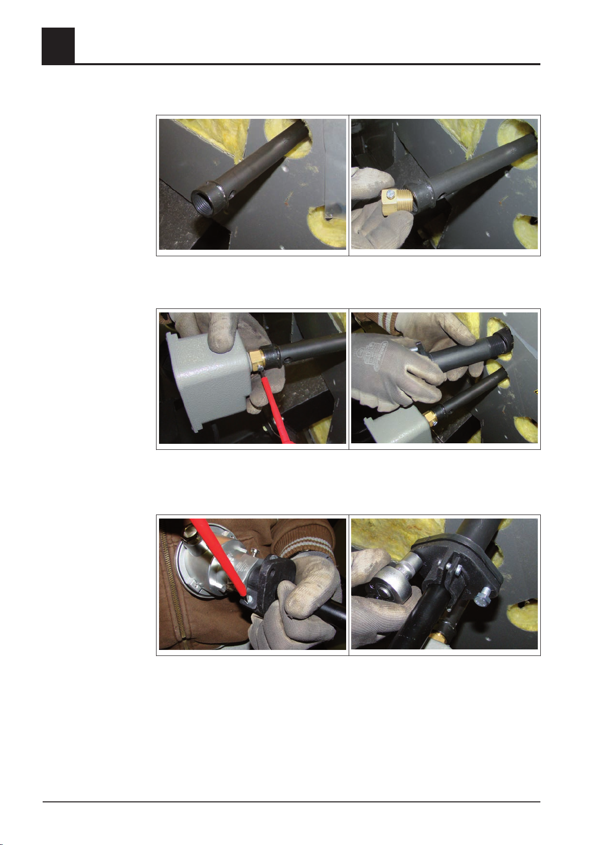
4.5.18 Installing overpressure monitor and temperature sensor
❒ Screw in the extension socket above the stoker unit
Screw in a brass bushing at the extension socket
❒
❒ Insert the overpressure monitor and tighten the locating screw gently
❒
Screw in the flange pipe of the combustion chamber temperature sensor above
the overpressure sensor
❒ Loosen the clamp screw at the mating flange
❒
Insert the temperature sensor and fasten the flange bolting
42 Froling GesmbH | A-4710 Grieskirchen, Industriestraße 12 | www.froling.com
Page 43
Assembly
Mounting steps
4.5.19 Installing the underpressure measurement
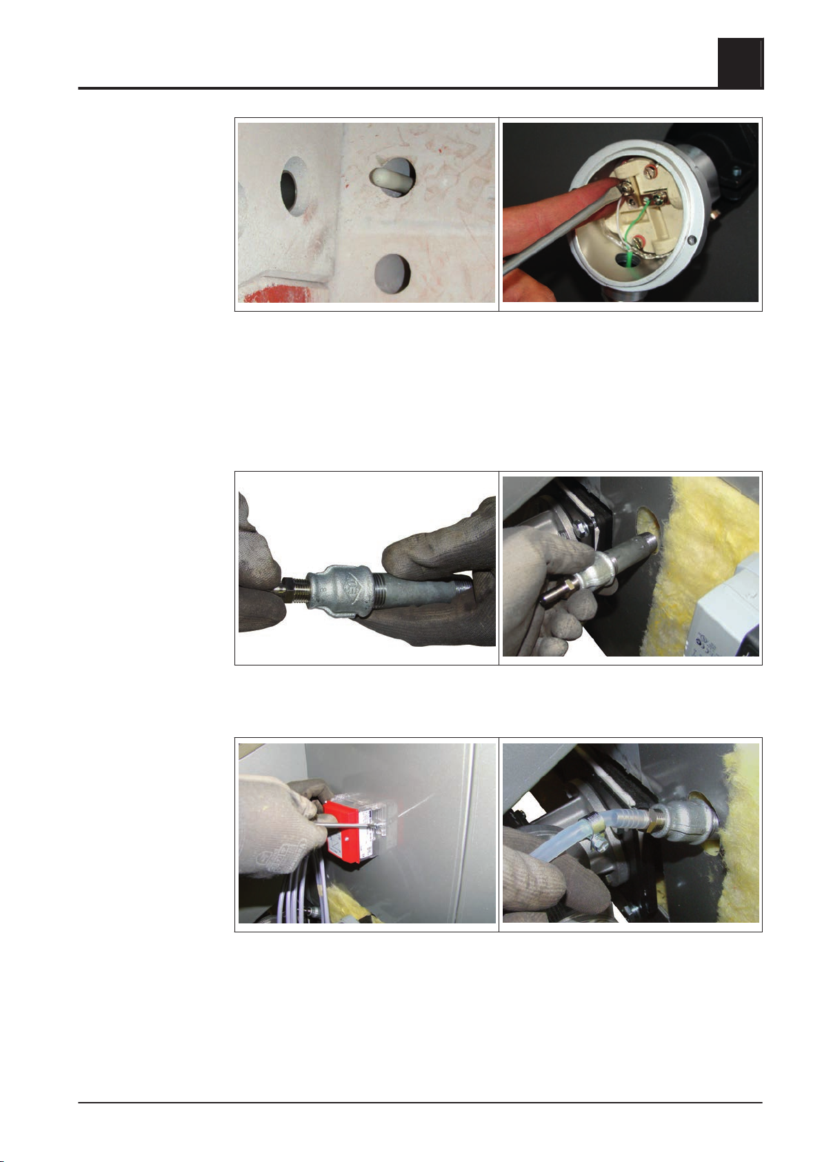
❒ Insert the temperature sensor until it extends approx. 30 - 50 mm (1 - 2 inch) into
the combustion chamber and fix this position with clamp screws
Remove the cover of the junction box and connect the balancing line
❒
- green wire at the clamp with the green mark
- white wire at the unmarked clamp
4
❒ Assemble the double nipple, the reducing socket and the hose nipple as illustrated
❒
Screw in the entire unit right beside the stoker
❒ Fix the underpressure sensor cartridge with 2 sheet metal screws at the insulating
side panel
Put the hose clamp onto the silicone hose, put on the hose nippel and fasten the
❒
hose clamp
Installation Instructions TX 150-250 | M1320112_en 43
Page 44
Assembly
4
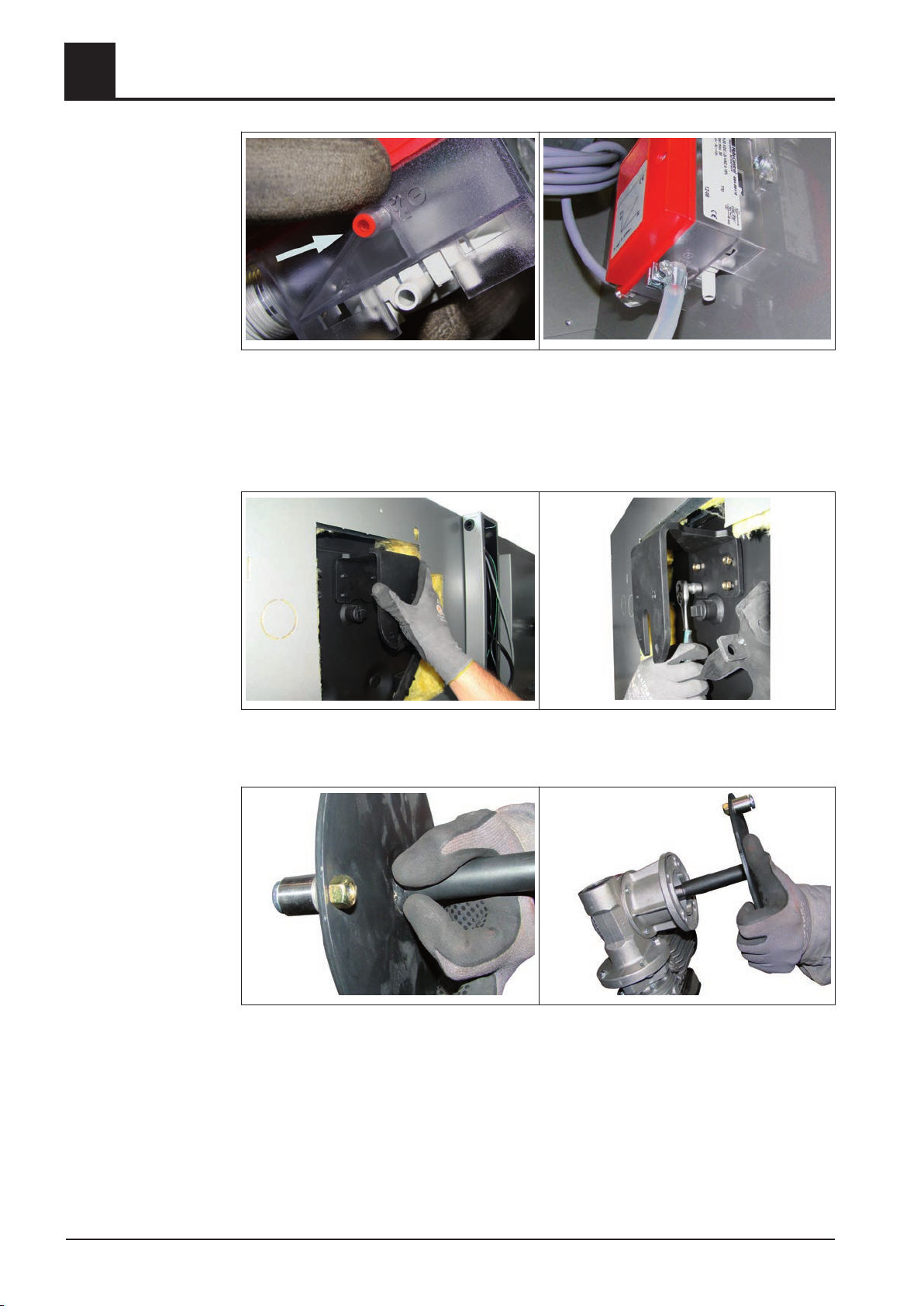
❒ Connect the other end of the silicone hose to the underpressure sensor cartridge
at nipple '-' with a hose clamp
➥ Do not remove the red reducing plug!
Mounting steps
4.5.20 Installing the WOS drive
❒ Put on the bracket to the stud at the heat exchanger and fix it with 4 washers M8
and lock nuts M8
❒ Mount shouldered bolts M8x20, bushing and lock nuts M8 at WOS disk as illustra‐
ted
❒
Insert WOS disk at the gear motor
44 Froling GesmbH | A-4710 Grieskirchen, Industriestraße 12 | www.froling.com
Page 45
Assembly
Mounting steps
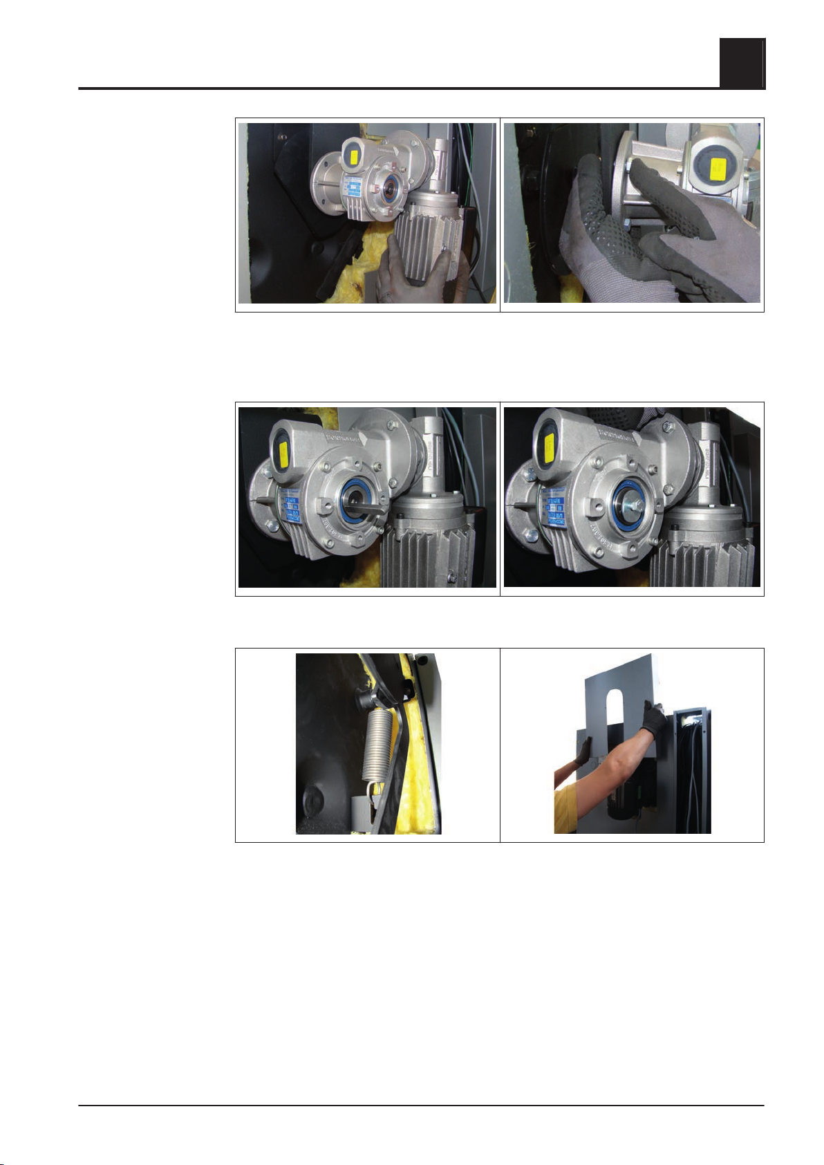
❒ Position the entire unit at the bracket so that the motor points downwards
Fix the motor with 4 hexagonal bolts M8x30, washers M8 and lock nuts M8 at the
❒
bracket
4
❒ Insert the key and lock it
❒ Hook on the tension spring at the WOS lever, tighten it and hook it on at the lug
Thread the WOS cover from above behind the WOS drive and hook the stud into
❒
the slots at the insulating side panel
Installation Instructions TX 150-250 | M1320112_en 45
Page 46
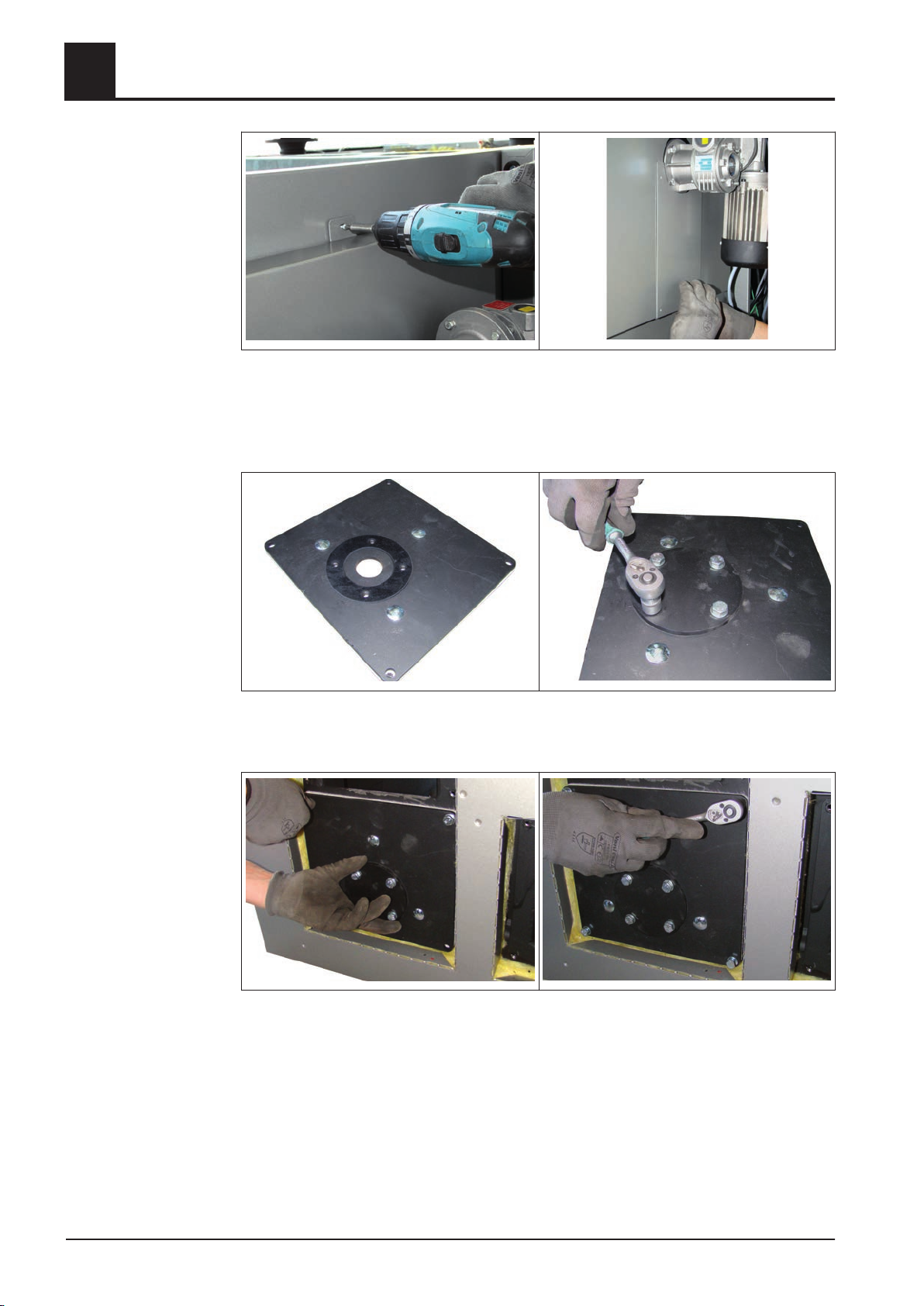
Assembly
4
❒ Fix the cover at the top part with a sheet metal screw
Fix the cover plate below the WOS drive with sheet metal screws
❒
Mounting steps
4.5.21 Heat exchanger ash removal unit with ash box
❒ Put the rubber seal on the flange plate
❒
Set on the sealing plate and fix it with 4 hexagonal bolts M8x16 and washers M8
❒ Mount the flange plate at the back of the heat exchanger with 4 hexagonal bolts
M8x20
46 Froling GesmbH | A-4710 Grieskirchen, Industriestraße 12 | www.froling.com
Page 47
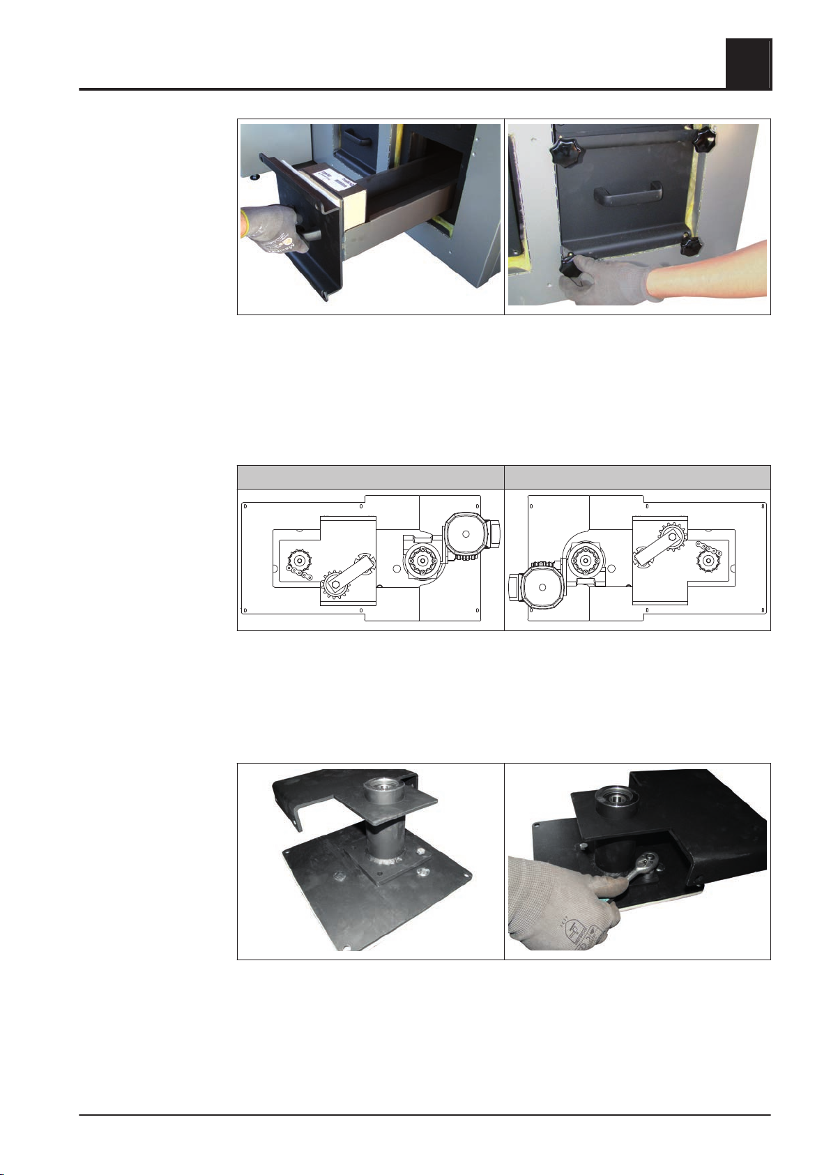
Assembly
Mounting steps
4.5.22 Heat exchanger ash removal unit with ash screw (optional)
4
❒ Slide in the ash box at the front of the heat exchanger and fix it with 4 star knob
screws
Installing the actuator of the ash screw
Heat exchanger right Heat exchanger left
The following steps show the assembly of the automatic heat exchanger ash removal
unit for boilers with the heat exchanger on the right. If the heat exchanger is on the
left, the steps should be adjusted appropriately. Please note that the chain tensioner
points downwards when the heat exchanger is on the right. In case of a heat exchang‐
er on the left, the chain tensioner points upwards.
❒ Fix the bearing block at the flange plate with 4 hexagonal bolts M8x16 and wash‐
ers M8
Installation Instructions TX 150-250 | M1320112_en 47
Page 48
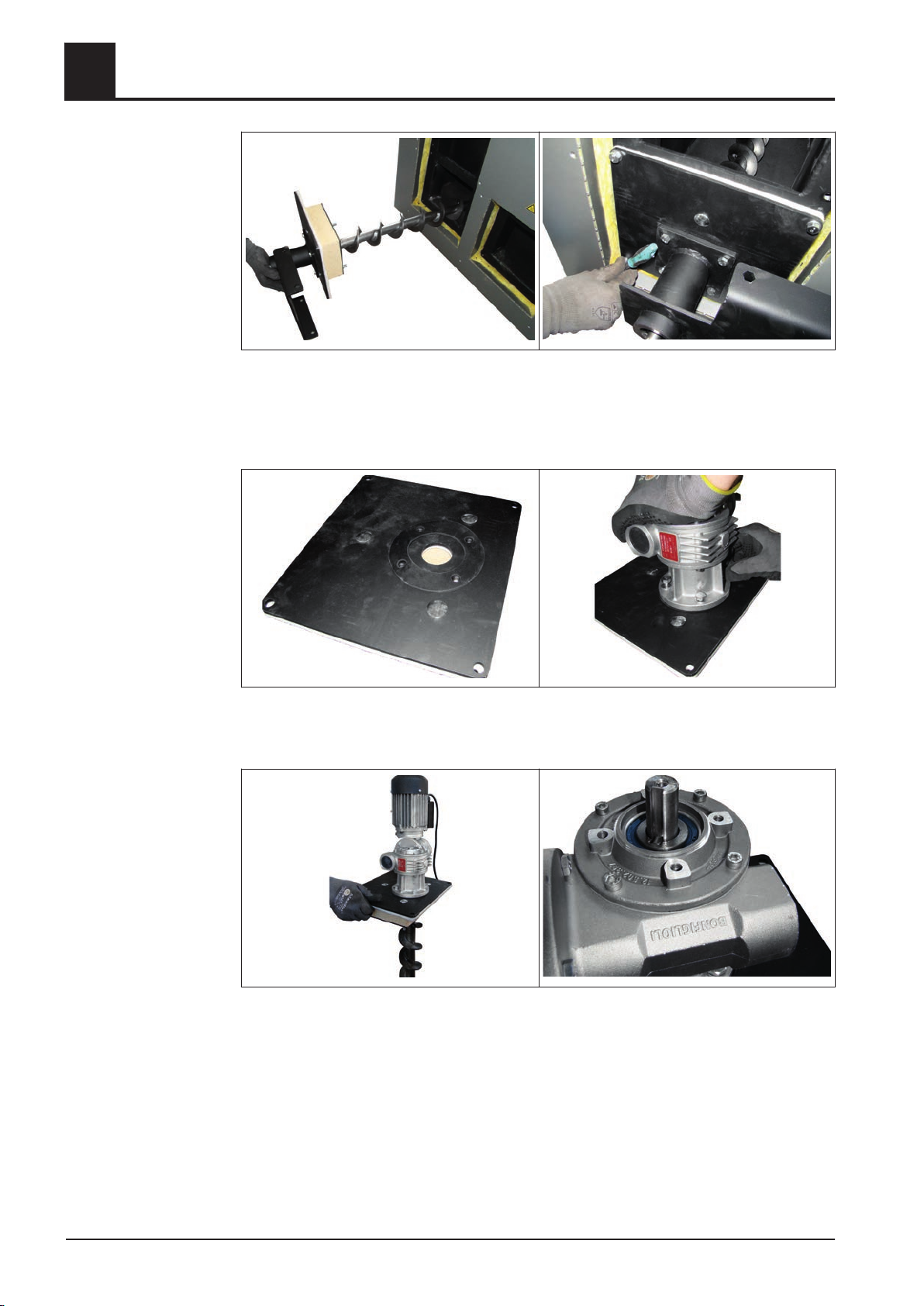
4
Assembly
Mounting steps
❒ Slide in the ash screw at the pedestal. Insert the entire unit at the back of the heat
exchanger below the ID fan connection
Fix the flange plate with 4 hexagonal bolts M8x20 and washers M8 at the heat ex‐
❒
changer
❒ Put the rubber seal at the second flange plate
❒
Put the gear motor onto and fix it with 4 hexagonal bolts M8x16
❒ Thread in the ash screw at the flange plate and gear motor and push it entirely
through
48 Froling GesmbH | A-4710 Grieskirchen, Industriestraße 12 | www.froling.com
Page 49
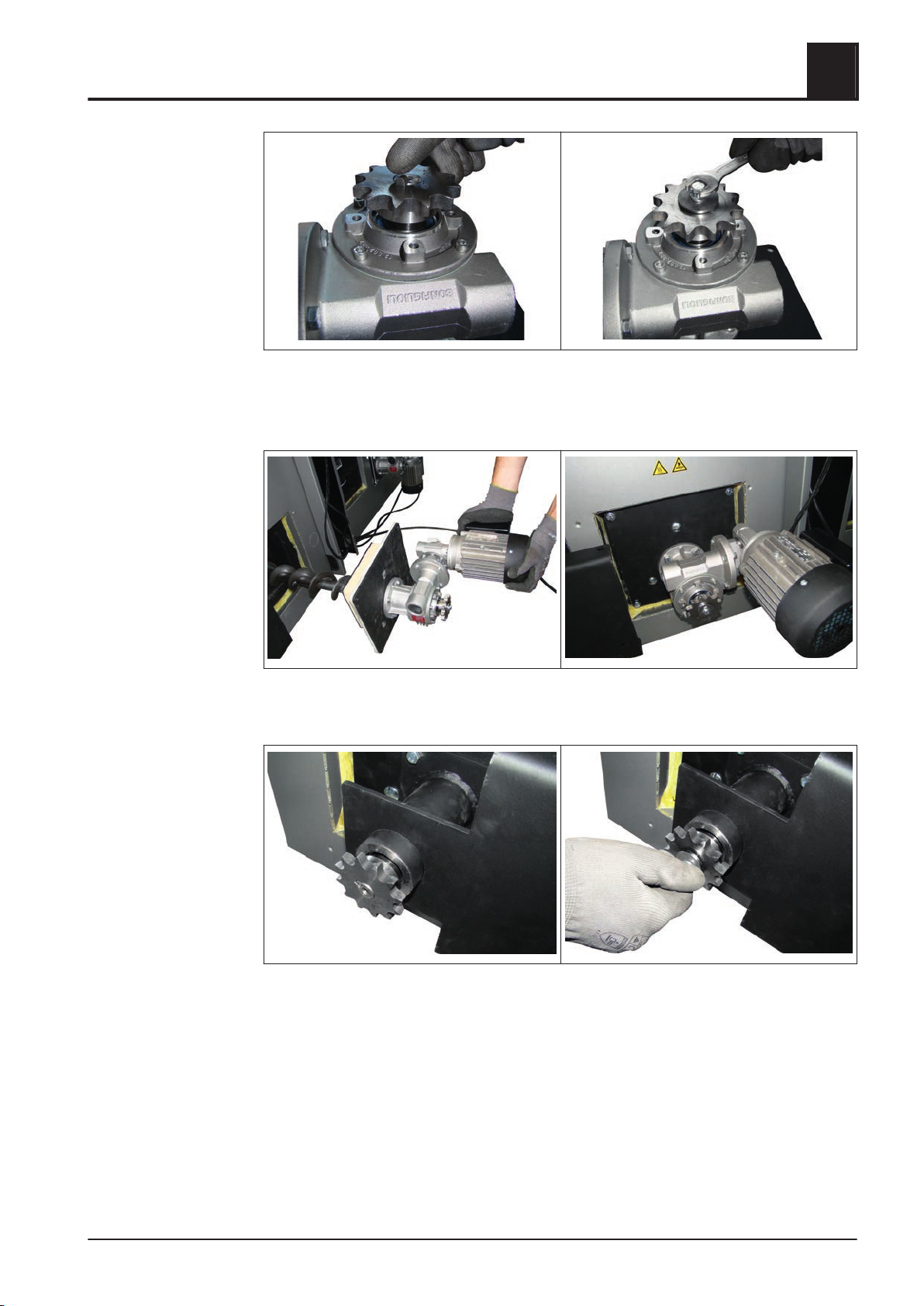
Assembly
Mounting steps
❒ Put on the chain wheel at the shaft of the ash screw and insert the key
Secure the key with a washer Ø30 mm (1.18 inch), a split washer M6 and an hex‐
❒
agonal bolt M6x16
4
❒ Slide in the entire unit at the heat exchanger and fix it with each 4 hexagonal bolts
M8x20 and washers M8
❒ Put on the second chain wheel at the shaft of the ash screw at the pedestal and
insert the key
Secure the key with a washer Ø30 mm (1.18 inch), a split washer M6 and an hex‐
❒
agonal bolt M6x16
Installation Instructions TX 150-250 | M1320112_en 49
Page 50
4
Assembly
Mounting steps
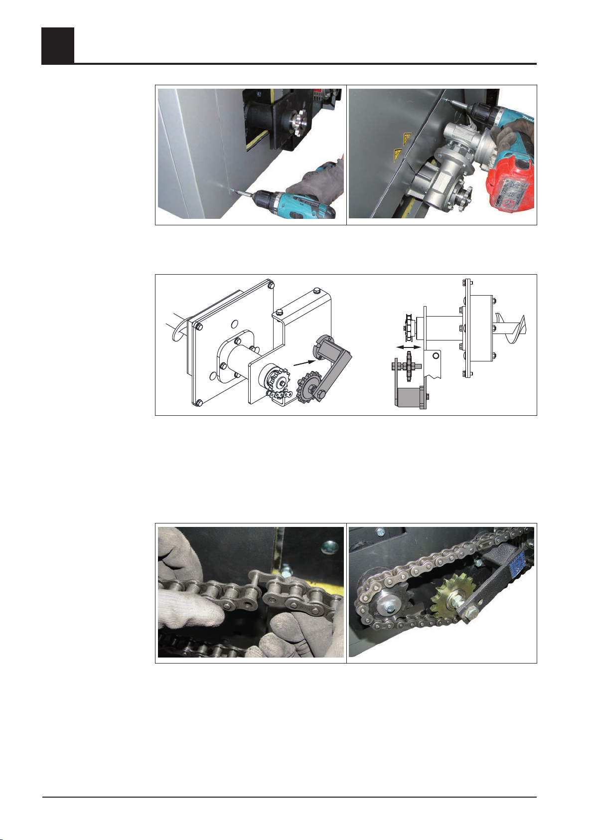
❒ Mount split cover plate behind the pedestal and gear motor with sheet metal
screws at the insulating side panel
❒ Mount chain tensioner with hexagonal bolts M10x30 and split washer M10 at the
pedestal
➥ Engage the chain tensioner at the stud of the pedestal so that sufficient tension
is generated at the chain
Kettenrad am Kettenspanner durch Verdrehen der Sechskantmuttern so einstell‐
❒
en, dass alle drei Kettenräder fluchtend ausgerichtet sind
❒ Put the roller chain over both chain wheels, tighten the chain and connect it at the
connecting link
❒
Secure the connecting link with a clip connector
50 Froling GesmbH | A-4710 Grieskirchen, Industriestraße 12 | www.froling.com
Page 51
Assembly
Mounting steps
4
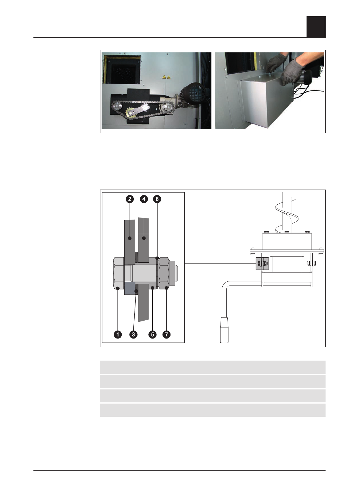
❒ Finally put on the cover hood and fix it with 4 hexagonal bolts M8x16 at the pedes‐
tal
Mount counterpart with captive screws
❒
Installing the ash boxes
1 Hexagonal bolt M8x25 2 Ash removal flange
3 Plate washer 4 Locking lever
5 Bushing 6 Lock washer M8
7 Lock nut M8
Installation Instructions TX 150-250 | M1320112_en 51
Page 52
4
Assembly
Mounting steps
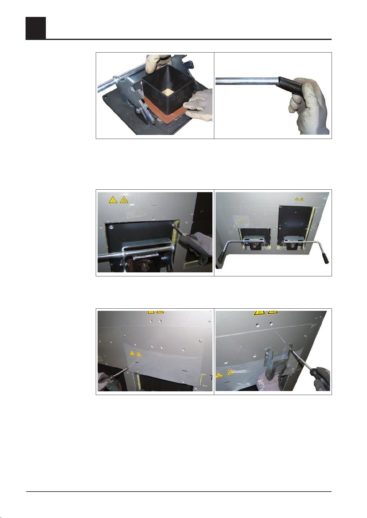
❒ Mount the locking lever at the ash removal flange as seen in the illustration above
Put the rubber seal over the channel of the ash removal flange
❒
❒ Put the plastic handle on the locking lever
➥ Use a rubber mallet
❒ Fix both ash removal flanges with 4 hexagonal bolts M8x20 and washers M8
➥ Place the flanges that way, that the locking levers are positioned outside
❒ Mount the cover plate above the exterior ash removal flange
Mount the retainer for the safety limit switch above the ash removal flange at the
❒
insulating side panel respectively at the cover plate with sheet metal screws
➥ Place the retainer above the right corner
➥ Do not fasten screws yet
52 Froling GesmbH | A-4710 Grieskirchen, Industriestraße 12 | www.froling.com
Page 53
Assembly
Mounting steps
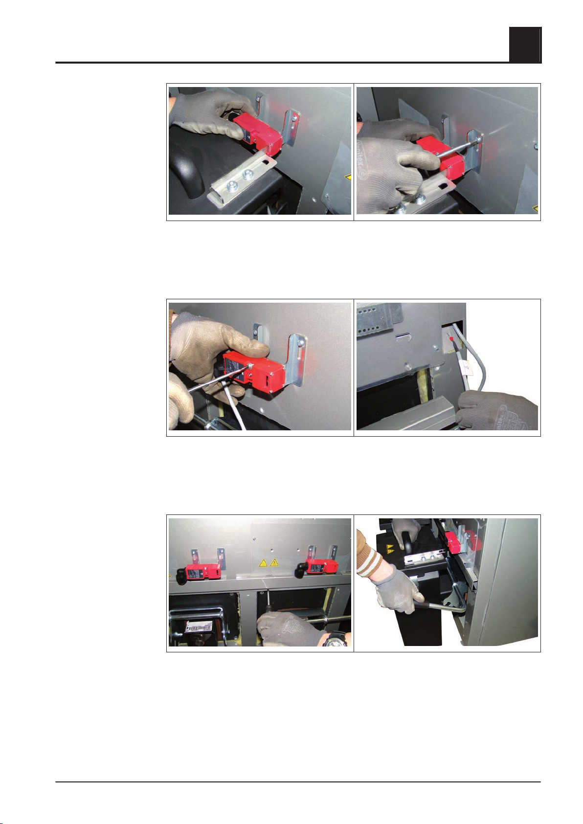
❒ Put the ash box onto the ash removal flange and place the safety limit switch at
the retainer
Slide key plate on the ashbox cover into the safety limit switch
❒
❒ Fasten screwings at the retainer
4
❒ Fix the safety limit switch with 2 self-tapping screws M4x30 at the retainer
Turn cable gland of the limit switch by 90° if necessary
❒
❒ Bend both lugs at the insulating side panel and lay the cable of the safety limit
switch upwards to the switch cabinet
❒ Put the ash boxes on and fix them with the locking levers
Put the cable channel below the safety limit switch on and fix it with sheet metal
❒
screws
Installation Instructions TX 150-250 | M1320112_en 53
Page 54
Assembly
4
Mounting steps
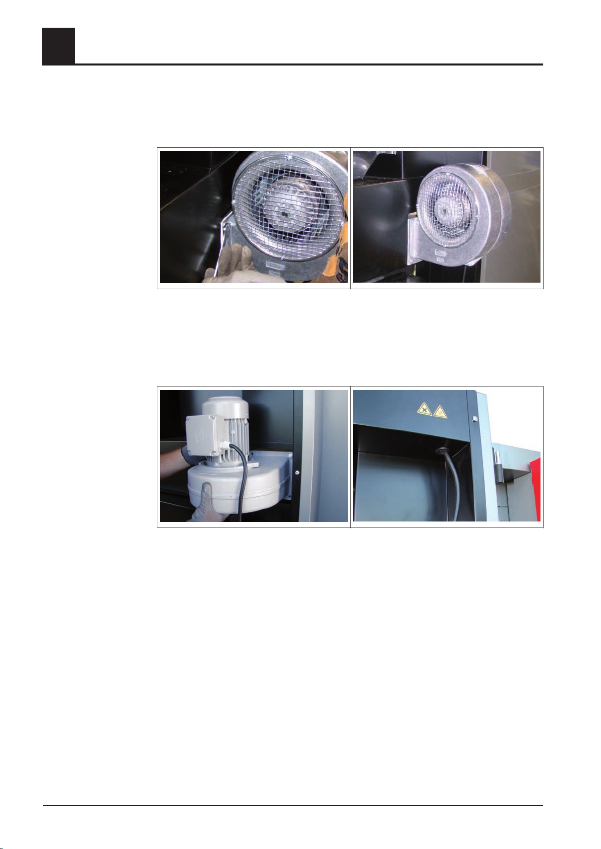
4.5.23 Installing the combustion air blower fan
Combustion air blower fan for TX 150:
❒ Mount the combustion air blower fan with ceramic fibre seal above the combustion
chamber door with 4 hexagonal bolts M6x16 and washers M6
➥ The louver has to point to the middle of the fire box
Combustion air blower fan for TX 200/250:
❒ Mount the combustion air blower fan with ceramic fibre seal above the combustion
chamber door with 4 hexagonal bolts M6x16 and washers M6
➥ The louver has to point downwards
Run the connection cable upwards and lay it to the switch cabinet through the
❒
opening in the frame element
54 Froling GesmbH | A-4710 Grieskirchen, Industriestraße 12 | www.froling.com
Page 55
Assembly
Mounting steps
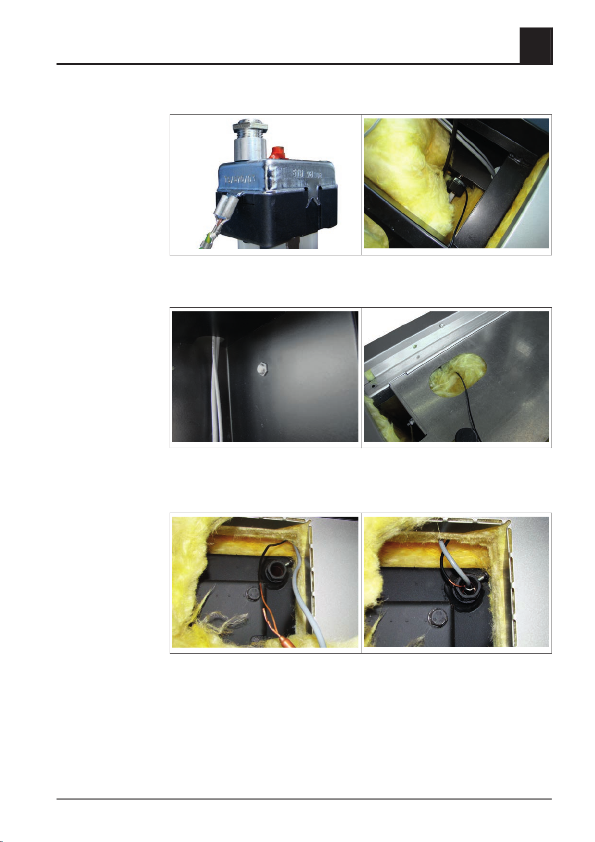
4.5.24 Installing the STL and the boiler sensor
❒ Unscrew the washer at the Safety Temperature Limiter (STL)
Push the STL from the behind through the frame element
❒
4
❒ Fix the STL at the frame element with a locating screw
❒
Put the capillary sensor through the opening at the cable tray and lay it to the ther‐
mowell at the heat exchanger
❒ Put the capillary sensor and the boiler sensor behind the insulating side panel
through and insert it with a clamp spring at the thermowell
Installation Instructions TX 150-250 | M1320112_en 55
Page 56
Assembly
4
Mounting steps
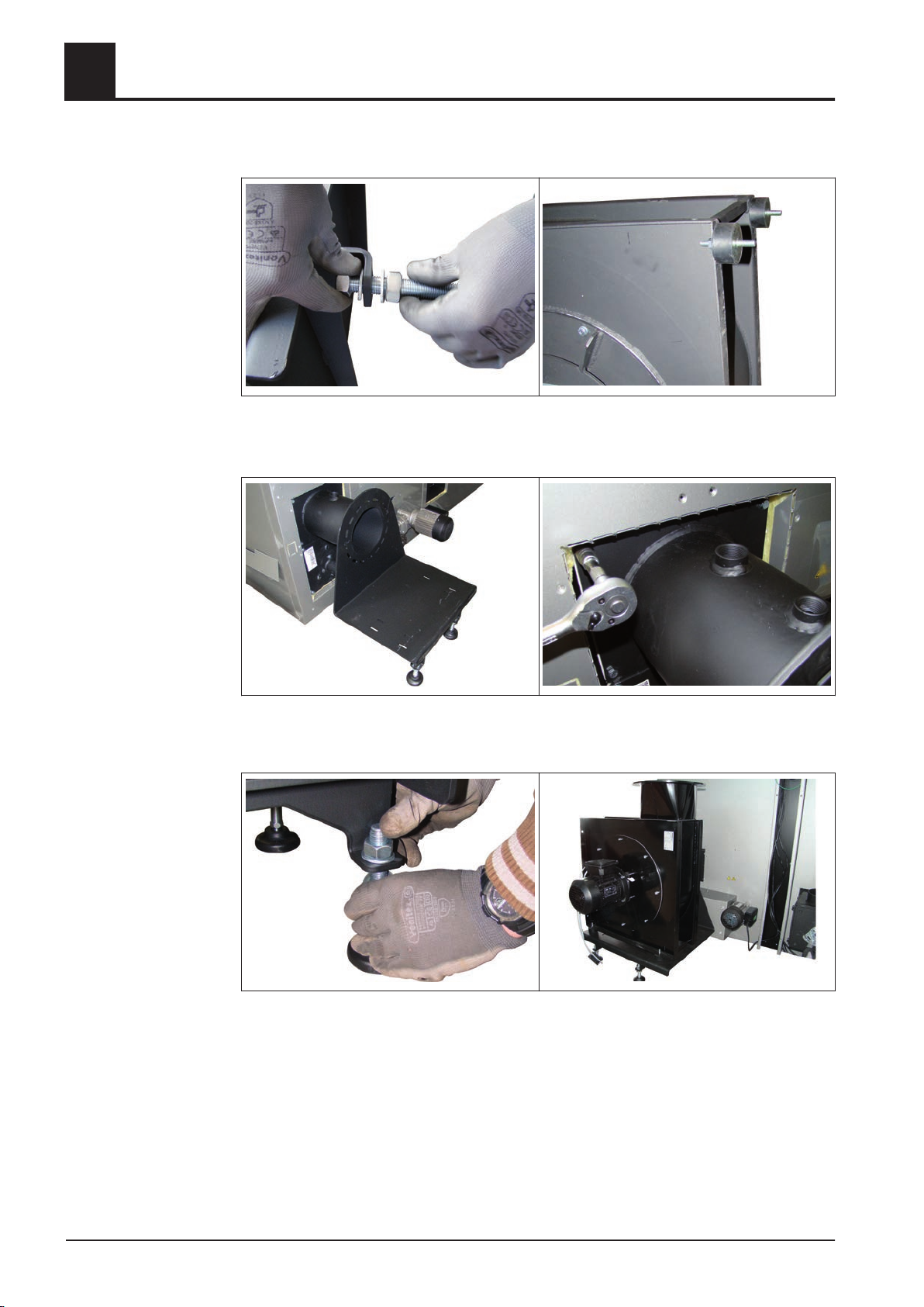
4.5.25 Installing the ID fan
❒ Mount the supports on the left and the right of the ID console
Put 4 rubber buffers onto the intended slotted holes at the ID fan
❒
❒ Place the ID console incl. seal at the flange and fix it with each 4 hexagonal bolts
M8x20 and washers M8
❒ Level the ID console via supports
Put the ID fan on the ID console as illustrated
❒
56 Froling GesmbH | A-4710 Grieskirchen, Industriestraße 12 | www.froling.com
Page 57
Assembly
Mounting steps
4
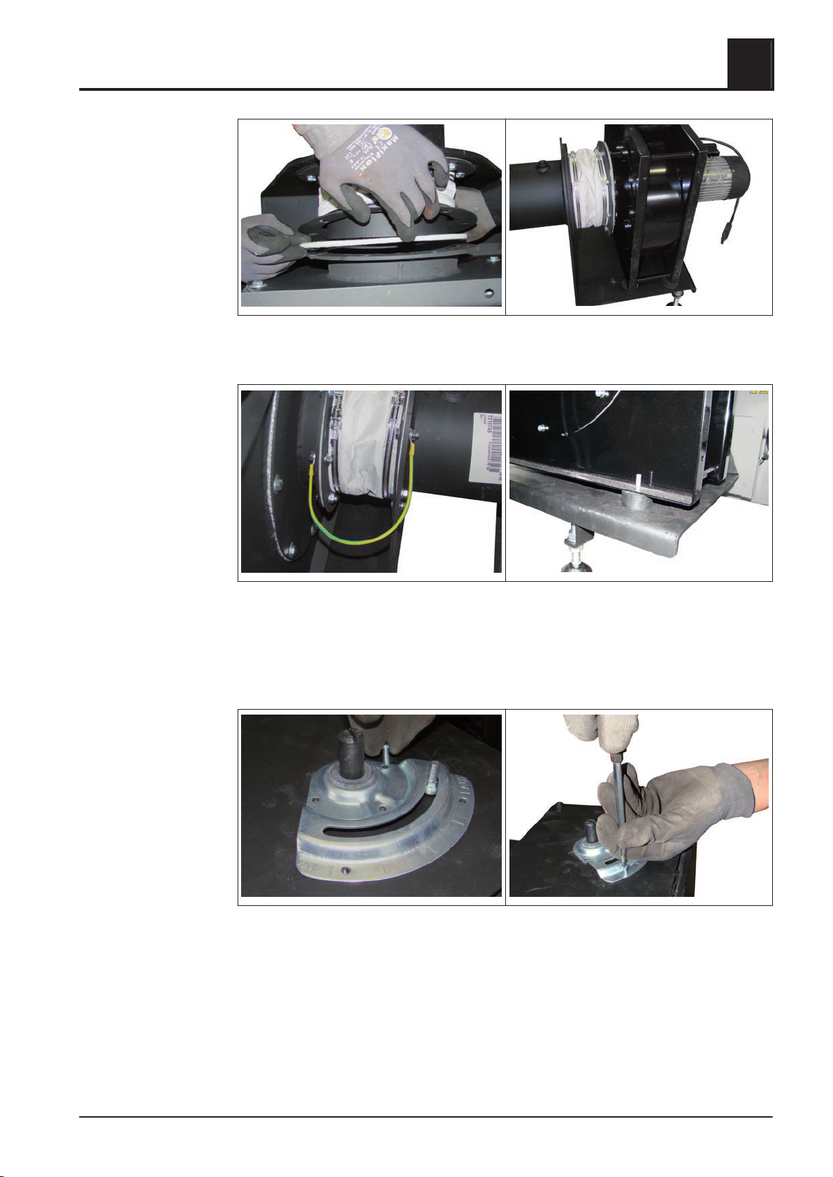
❒ Mount the flue gas pipe compensator with ceramic fibre seals between ID fan and
flange of the ID console
❒ Screw the included earth wire as potential equalization as illustrated on the left
and the right of the flange
Screw the rubber buffers to the ID console
❒
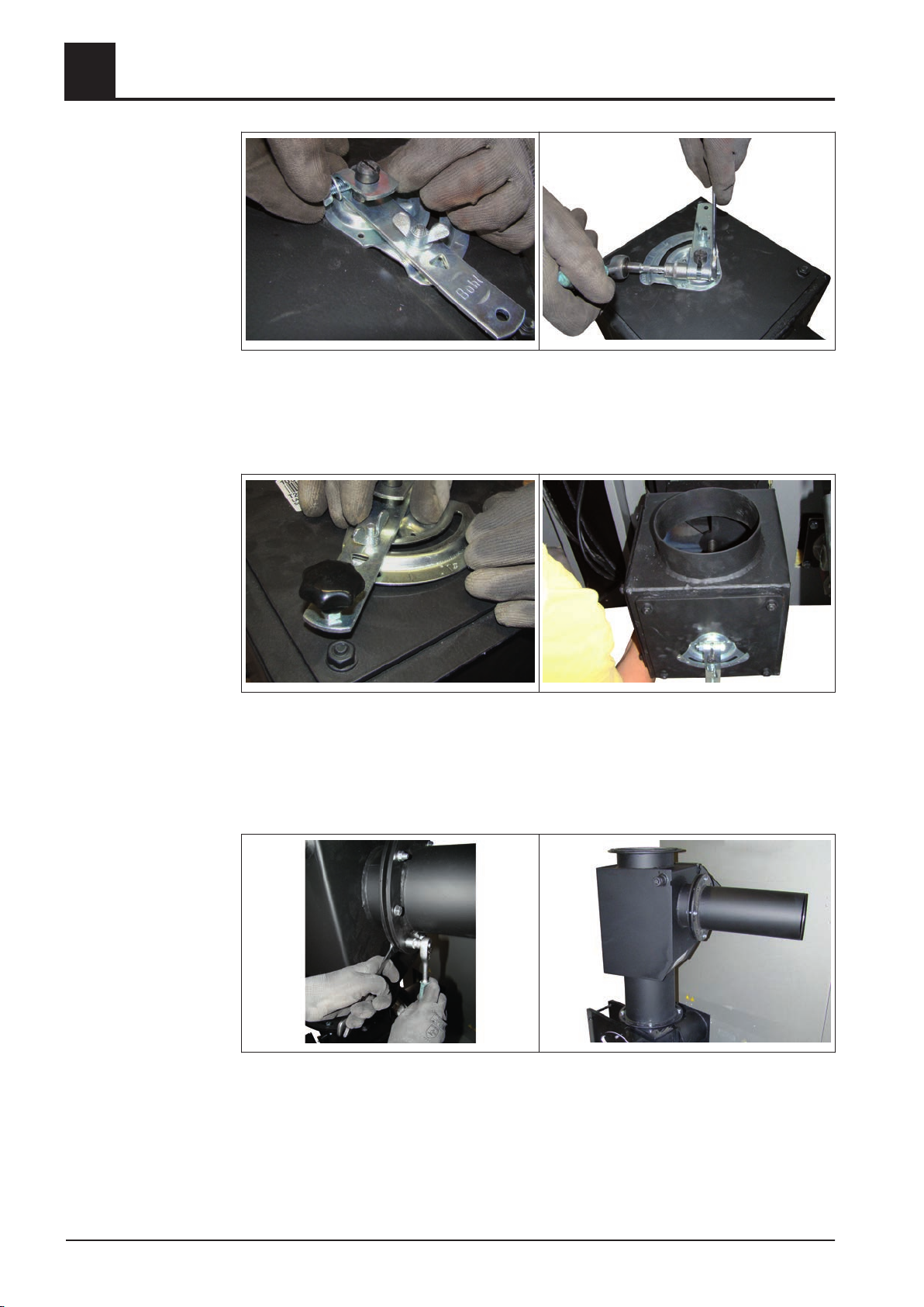
4.5.26 Installing the FGR air box (optional)
❒ Insert pan cap screw from the back side of the base plate
❒
Put the base plate over the shaft of the FGR flap and fix it with 5 zylinder screws
to the FGR air box
Installation Instructions TX 150-250 | M1320112_en 57
Page 58
4
Mounting steps
❒ Set the FGR flap with a nipper to the right-hand stop
Put on the lever of the air flap regulator at the shaft and the shouldered bolt and
❒
set it to the right end of the scale
❒ Fix the lever with the included fastening material and wing nut
Assembly
❒ Mount the included star knob at the lever
Mount the FGR air box to the left of the stoker unit at the retort with each 4 hexag‐
❒
onal bolts M8x20 and washers M8
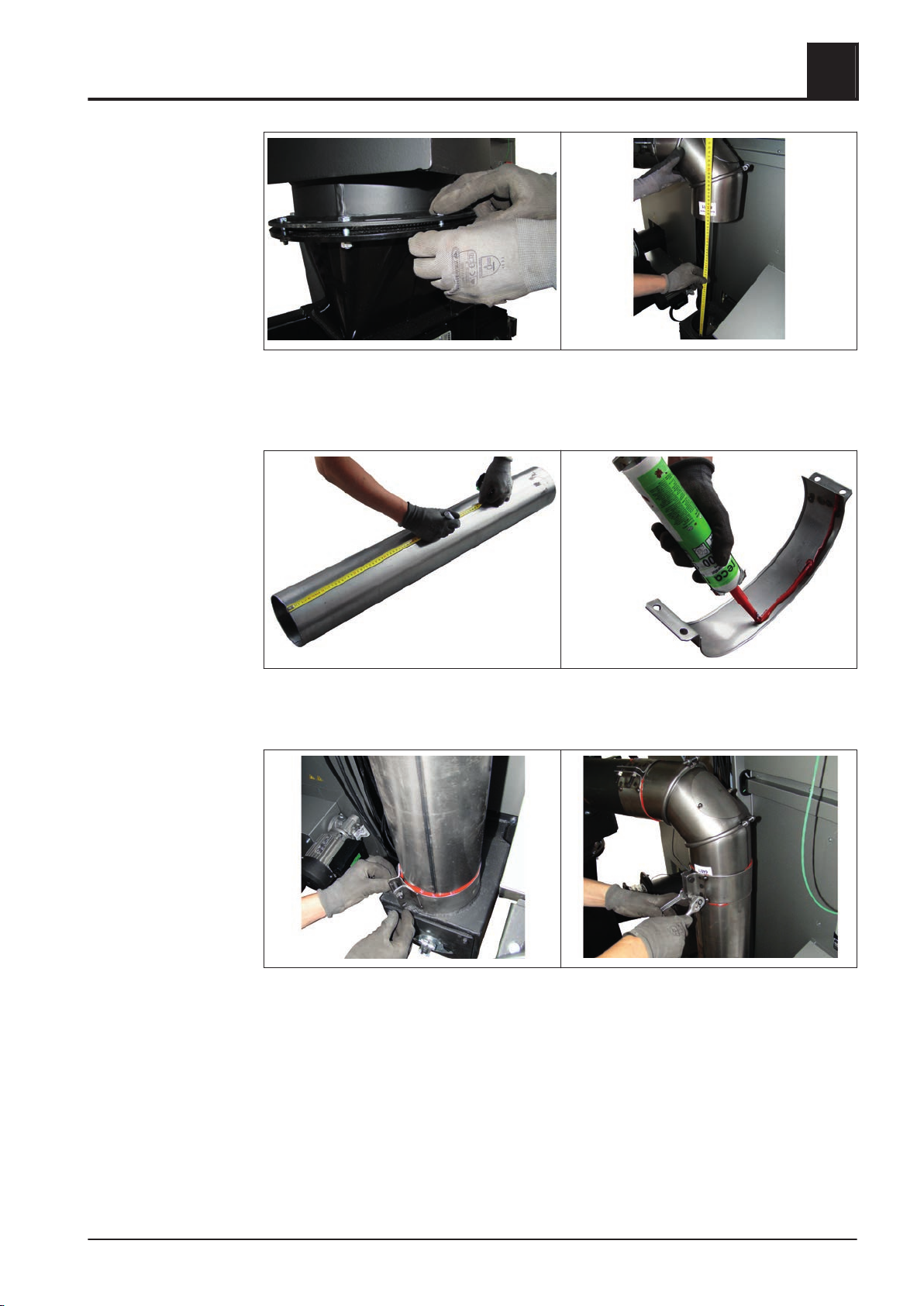
4.5.27 Installing the flue gas recirculation FGR (optional)
❒ Mount the tube with flange at the flue gas collecting box
❒
Place the flue gas collecting box at the ID fan that way, that the tube points to the
FRG air box at the retort
58 Froling GesmbH | A-4710 Grieskirchen, Industriestraße 12 | www.froling.com
Page 59
Assembly
Mounting steps
❒ Fix the flue gas collecting box at the ID fan
Place the flue gas pipe elbow at the tube and measure the distance between flue
❒
gas pipe elbow and FGR air box
4
❒ Cut the tube to the appropriate length
❒
Apply refractory silicon to the flue gas pipe clamps
❒ Assemble the entire FGR piping and fix the flue gas pipe clamps
Installation Instructions TX 150-250 | M1320112_en 59
Page 60
Assembly
4
Mounting steps
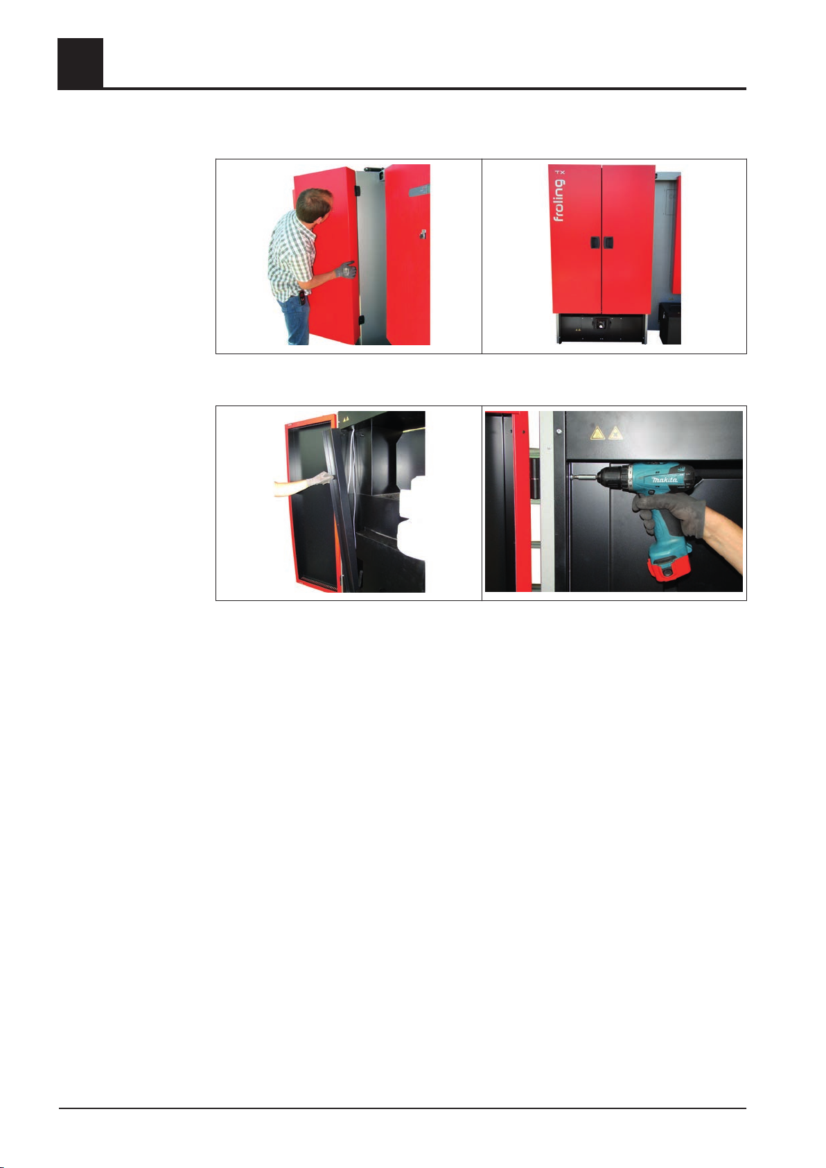
4.5.28 Installing insulating door and cover plates
❒ Mount the insulating doors to the door hinges at the frame element
❒ Put on the cable duct cover and fix it with self-tapping screws
60 Froling GesmbH | A-4710 Grieskirchen, Industriestraße 12 | www.froling.com
Page 61
Assembly
Electrical connection
4.6 Electrical connection
❒
❒ Connect cables in the switch cabinet according to the wiring diagram
❒ Secure cables to the strain relief bar with cable ties
4
DANGER
When working on electrical components:
Risk of electrocution!
When work is carried out on electrical components:
❒ Only have work carried out by a qualified electrician
❒ Observe the applicable standards and regulations
➥ Work must not be carried out on electrical components by unauthorised
people
Lay cables of all components to the switch cabinet
➥ For connection see corresponding documentation for firewood boiler
Notes on laying cables
▪ The cables of the individual units may have excess length. These cables should
be coiled in the cable duct.
▪ Spread the coils of excess cable over the entire cable ducts to prevent the cable
ducts from being overfilled!
▪ Bind the freely hanging cable to the drive motors using cable ties. The cables must
not come into contact with the stoker duct!
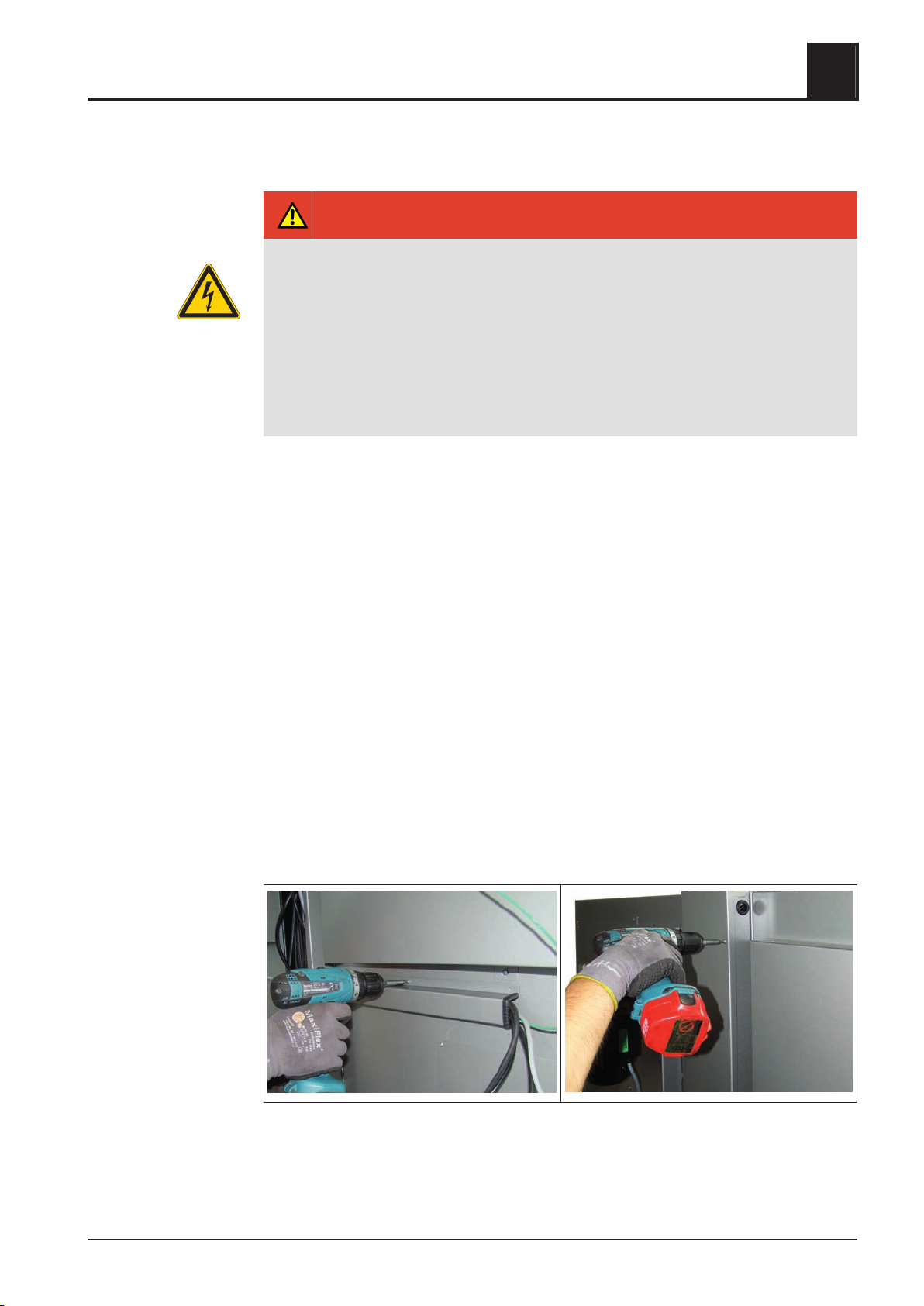
4.6.1 Installing insulating covers and cover plates
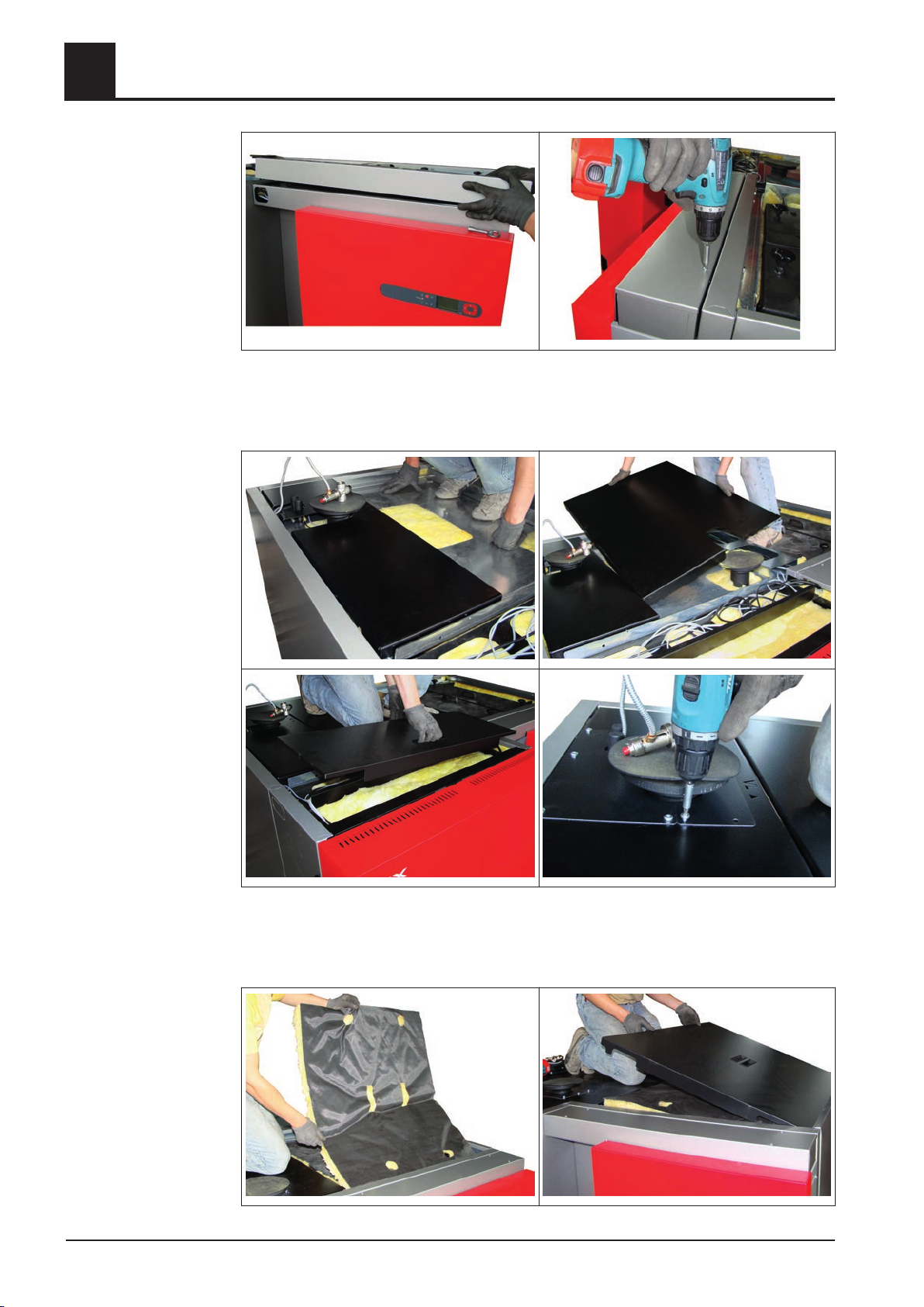
After wiring the components all cover plates and insulating covers must be installed:
❒ Mount cable ducts at the designated positions on the insulating side panels
❒
Mount cover plate of vertical cable duct on the back side of the boiler
Installation Instructions TX 150-250 | M1320112_en 61
Page 62
4
Assembly
Electrical connection
❒ Mount cover plate on cable duct of switch cabinet
➥ Illustration shows the switch cabinet of TX 200/250. In case of installing a TX
150 the cable duct is mounted below the switch cabinet
❒ Put on insulating covers on the boiler as seen at the pictures above
❒
Lay thermal discharge unit through the opening in the insulating cover and mount
cover plates
62 Froling GesmbH | A-4710 Grieskirchen, Industriestraße 12 | www.froling.com
Page 63

Assembly
Electrical connection
❒ Apply heat insulation mat on the heat exchanger cover an put on the insulating
cover
4
Installation Instructions TX 150-250 | M1320112_en 63
Page 64
4
4.7 Connecting the thermal discharge system
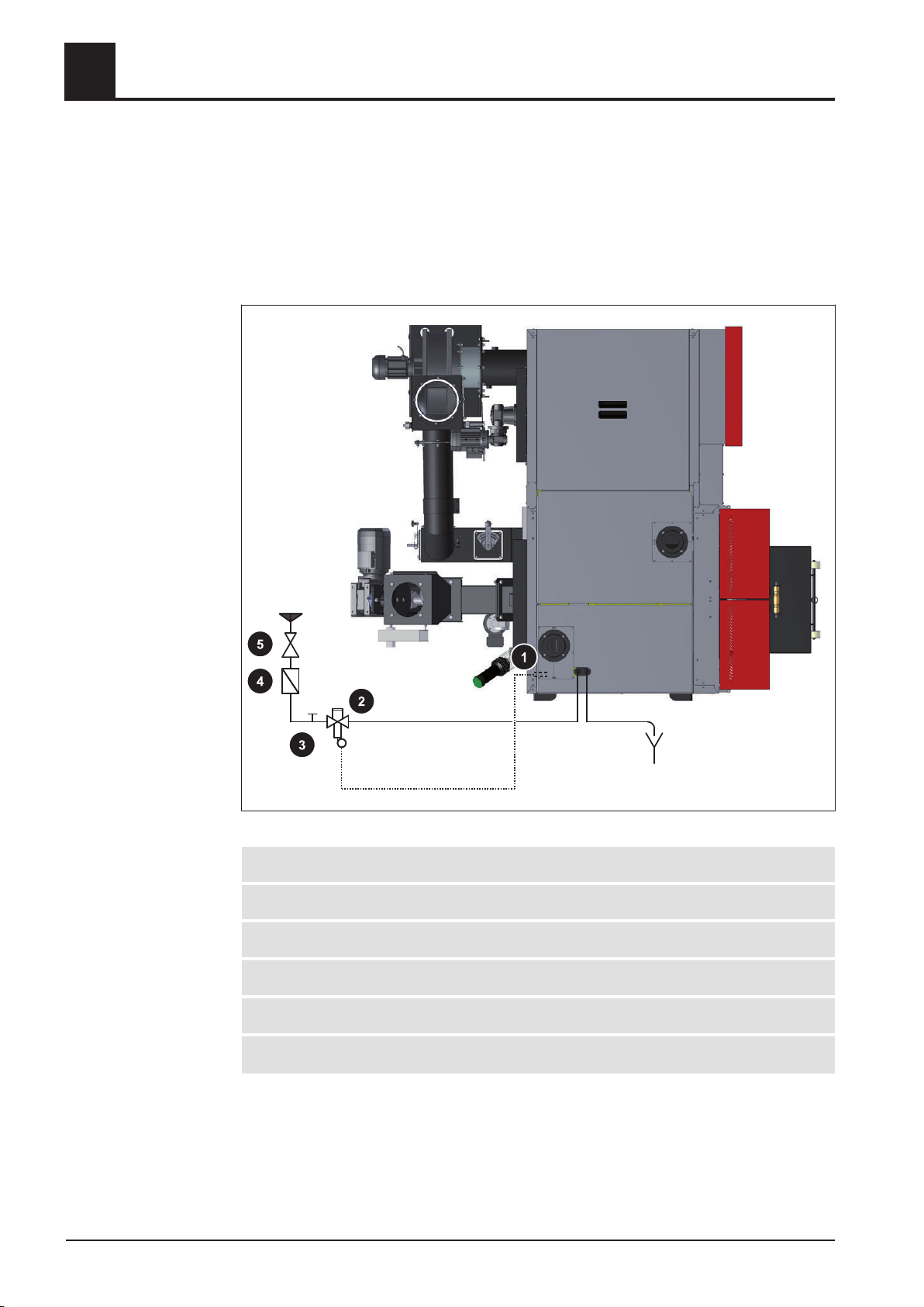
▪ The thermal discharge device must be connected in accordance with EN 303-5 as
shown in the following diagram!
The thermal discharge device must be connected to a pressurised mains water
▪
supply in such a way that it cannot be shut off!
Assembly
Connecting the thermal discharge system
1 Sensor of thermal discharge safety device
2 Thermal discharge safety device (opens at 95°C)
3 Cleaning valve (T-piece)
4 Dirt trap
5
Pressure reducing valve
1.Required when the cold water pressure is 6 bar. It must be impossible to shut off the connection manually. Minimum cold water pressure
= 2 bar
64 Froling GesmbH | A-4710 Grieskirchen, Industriestraße 12 | www.froling.com
1)
Page 65

Start-up
Before commissioning / configuring the boiler
5 Start-up
5.1 Before commissioning / configuring the boiler
The boiler must be adjusted to the heating system during commissioning.
Optimum efficiency and efficient, low-emission operation can only be guaranteed
if the system is set up by trained professionals and the standard factory settings
are observed.
Take the following precautions:
❒
Initial startup should be carried out with an authorised installer or with Froling
customer services
Adjust the boiler controller to the system type
❒
❒ Apply boiler standard values
NOTICE! The keypad assignment and the steps necessary to modify the parameters
are detailed in the operating instructions for the boiler control unit.
❒ Check the system pressure of the heating system
❒ Check that the heating system is completely vented
❒ Check that the safety devices are present and working correctly
❒ Check that there is sufficient ventilation in the boiler room
❒ Check the seal of the boiler
➥ All doors and inspection openings must be tightly sealed!
❒ Check that drives and actuators are working and turning in the right direction
NOTICE! For how to check the analogue and digital outputs, see the operating instruc‐
tions for the boiler controller
❒ Check that the door contact switch is working correctly
NOTICE! For how to check the digital inputs see the operating instructions for the boil‐
er controller.
5
NOTICE
Installation Instructions TX 150-250 | M1320112_en 65
Page 66
5
5.2 Initial startup
5.2.1 Permitted fuels
Note on standards
Wood pellets
Wood pellets made from natural wood with a diameter of 6 mm
EU: Fuel acc. to EN 14961 - Part 2: Wood pellets class A1 / D06
plus
or DIN
and/or: Certification program EN
plus
General note:
Before refilling the store, check for pellet dust and clean if necessary.
Wood chips
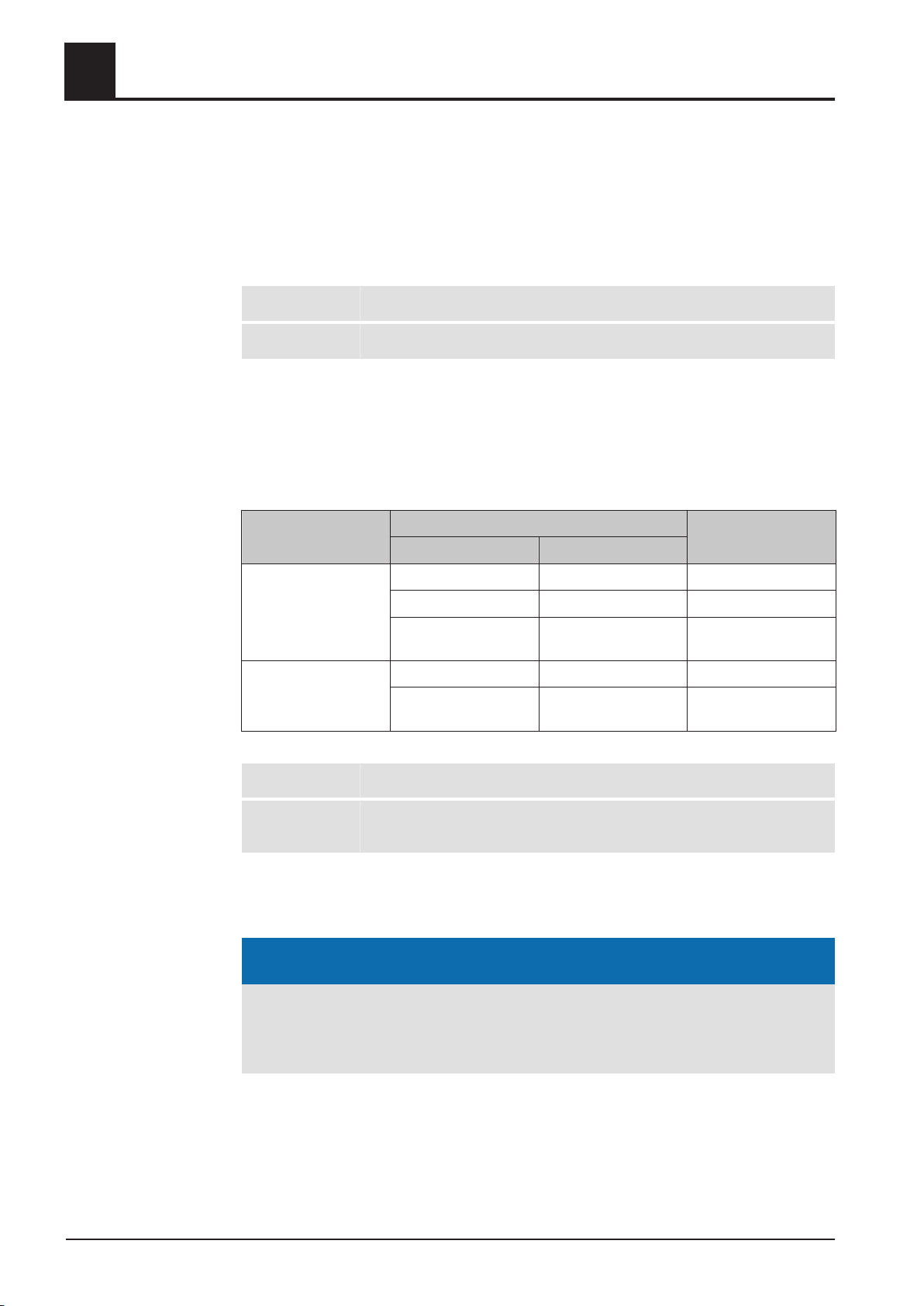
Criterion Designation as per Description acc. to
ÖNORM M 7133 EN 14961
Start-up
Initial startup
ÖNORM M 7133
Note on standards
5.2.2 Heating up for the first time
Water content W20 M20 Air-dried
W30 M30 Suitable for storage
W35 M35 Limited suitability for
storage
Size G30 P16A / P16B Fine wood chip
G50 P45A Medium-sized wood
chips
EU: Fuel acc. to EN 14961 - Part 4: Wood chips class A2 / P16A-P45A
Germany
also: Fuel class 4 (§3 of the 1st BImSchV in the last amended version)
NOTICE
If condensation escapes during the initial heat-up phase, this does not indicate a
fault.
❒
Tip: If this occurs, clean up using a cleaning rag.
66 Froling GesmbH | A-4710 Grieskirchen, Industriestraße 12 | www.froling.com
Page 67

Decommissioning
Mothballing
6 Decommissioning
6.1 Mothballing
6.2 Disassembly
6.3 Disposal
The following measures should be taken if the boiler is to remain out of service for
several weeks (e.g. during the summer):
Clean the boiler thoroughly and close the doors fully
❒
If the boiler is to remain out of service during the winter:
❒ Have the system completely drained by a qualified technician
To disassemble the system, follow the steps for assembly in reverse order.
❒ Ensure that the system is disposed of in an environmentally friendly way in ac‐
cordance with waste management regulations.
You can separate and clean recyclable materials and send them to a recycling
❒
centre.
❒ The combustion chamber must be disposed of as builders' waste.
6
➥ Protection against frost
Installation Instructions TX 150-250 | M1320112_en 67
Page 68

7
7 Appendix
7.1 Addresses
7.1.1 Address of manufacturer
7.1.2 Address of the installer
Appendix
Addresses
FRÖLING
Heizkessel- und Behälterbau GesmbH
Industriestaße 12
A-4710 Grieskirchen
AUSTRIA
TEL 0043 (0)7248 606 0
FAX 0043 (0) 7248 606 600
INTERNET www.froeling com
Stamp
68 Froling GesmbH | A-4710 Grieskirchen, Industriestraße 12 | www.froling.com
 Loading...