

Page 1
Installation Instructions
For Medium (15,000-18,500 btu) + Heavy duty (22,000-28,500 btu) Air Conditioner
READ BEFORE INSTALLING UNIT
INSTALLATION WARNINGS AND CAUTION
He Carefully read the Installation manual before beginning.
He Foilow each step as shown.
He Observe all local, state, and national electrical codes and by qualified, licensed, authorized personnel only.
9|c Pay attention to danger and safety notices.
To avoid risk of personal injury, property damage, or product damage due to the weight of this device and sharp edges that may
be exposed:
He
Air conditioners covered in this manual pose an excessive weight hazard. Two or more people are needed to move and install
the unit. Wear protective gloves whenever lifting or carrying the unit. AVOID the sharp metal fins of front and rear coils. To
prevent injury or strain, use proper lifting and carrying techniques when moving unit.
* Carefully Inspect location where air conditioner will be Installed. Be sure It will support the weight of the unit overan extended
period of time.
He
Handle air conditioner with care.
He
Make sure air conditioner does not fall during installation.
)k If a new electrical outlet Is required, have the outlet installed by a qualified electrician before Installing unit.
NOTE: DO NOT USE ANY SCREWS OTHER THAN THOSE SPECIFIED HERE
Preliminary instructions:
Do the following before starting to install unit. See illustrations below.
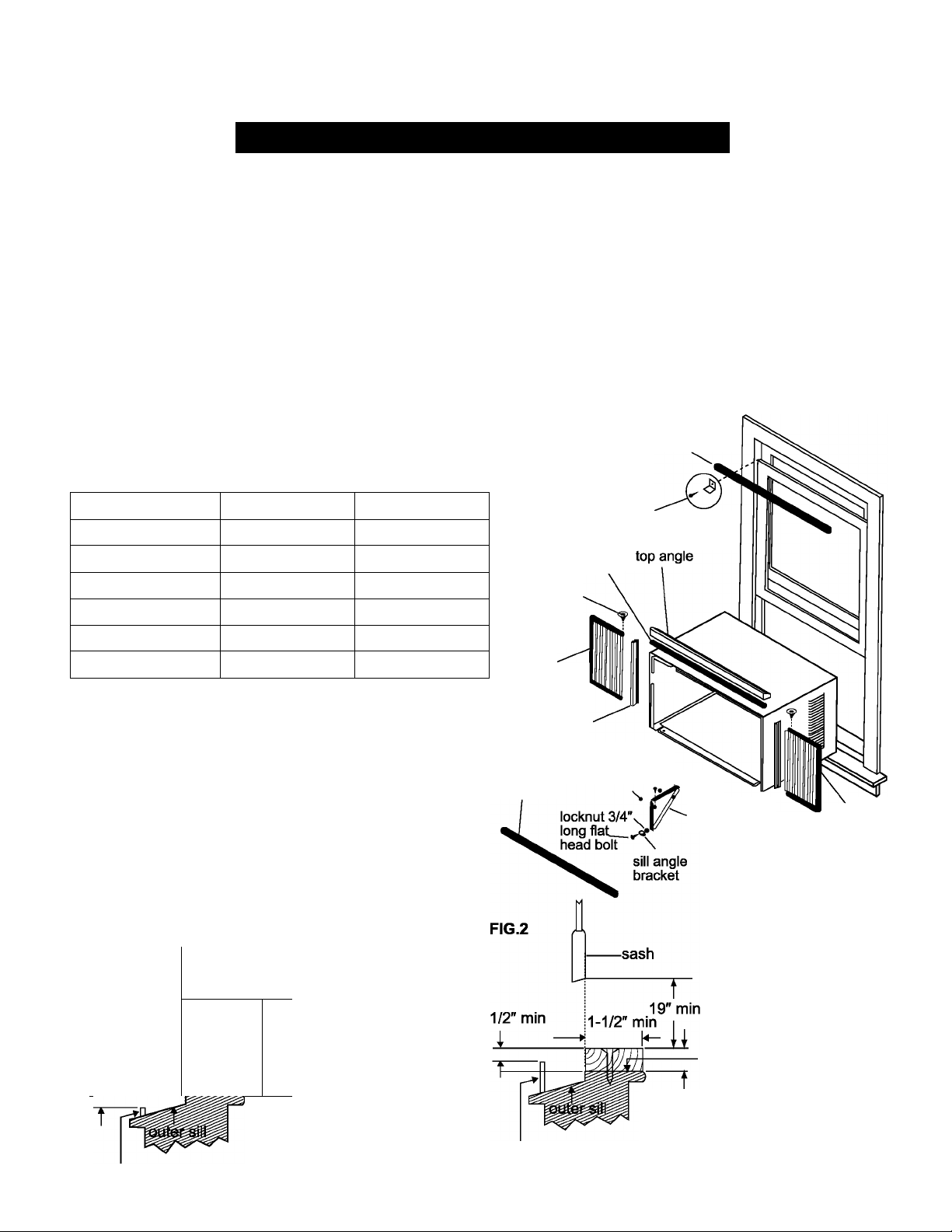
Check dimensions of your unit to determine model type:
Heavy duty
Capacity:
Unit Height: 18-5/8"
Unit Width: 26-1/2"
Min. Window Opening: 19-1/2"
Min. Window Width: 31"
Max. Window Width: 42"
22,000-28,500 BTU 15,000-18,500 BTU
Medium
17-5/8"
23-5/8"
18-1/2"
26-1/2"
40-1/2"
1. Check window opening size: the mounting parts
furnished with this air conditioner are made to install in
a wooden sili double-hung window. The standard parts
are for window dimensions listed above. Open sash to
a minimum of 19" (483mm). (FIG.1)
2. Check condition of window: all wood parts of window
must be in good shape and abie to firmly hold the needed
screws. If not, make repairs before instailing unit.
3. Check your storm windows: If your storm window
frame does not ailow the clearance required, correct by
adding a piece of wood as shown (FIG.2), or by removing
storm window whiie room air conditioner is being instailed.
FIG.1
N
------
sash
washer head
locking screw
frame
assembly
(left)
side retainer
bottom rail
seal to unit
safety lock and
1/2" long hex
head screw
foam gasket
window sash seal
1/2" long
screws and
locknuts >
window
support bracket
frame
assembly
(right)
1/2" min
i
I
inner sill
1
;
storm window frame or
other obstruction
19"
i k
min
storm window frame or
other obstruction
inner siil
board thickness as
required, along entire inner
window sili; fasten to inner
sill with two naiis or screws.
2020218A0886
1
Page 2
Installation Instructions
4. Check for anything that could block airflow
Check area outside of window for things such as shrubs, trees, or awnings,
wiii not stop proper air flow.
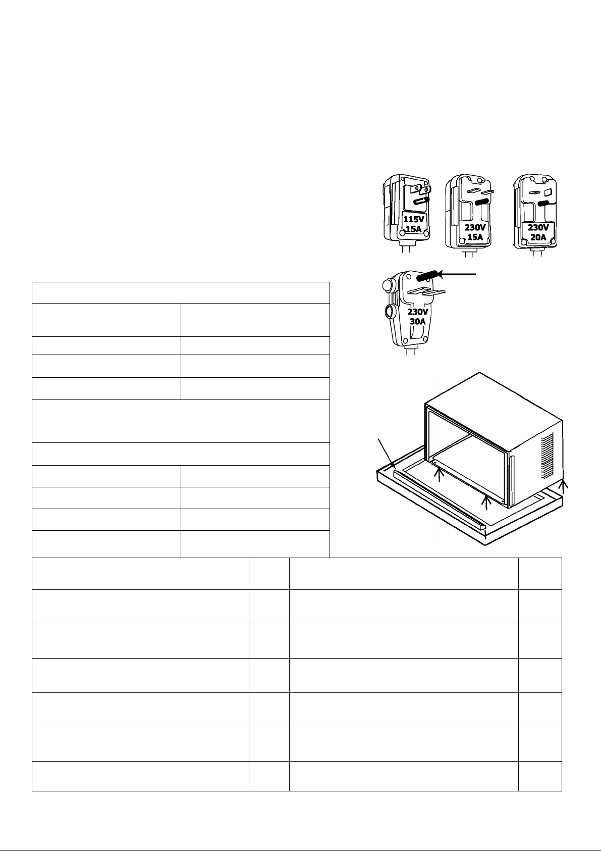
5. Check the available electrical service
Power supply must be the same as that shown on the unit sériai
namepiate. (See Use & Care Guide for sériai piate location.) Power
cord is 48" iong. Be sure you have an outlet near.
All models have a 3-prong service plug to provide proper service and
safe positive grouding. Do not change plug in any way. Do not use an
adapter plug. If your present wall outlet does not match your plug, call
a qualified electrician to make the needed change.
6. Carefully unpack air conditioner
Remove all packing material. Protect floor or other stable flat surface
with covering to prevent scratches from unit. With the aid of an
assistant, remove unit from styrofoam base and rest on protected
surface. Move and install unit with the aid of an assistant. Save
packing and shipping box for future unit storage.
Inside, be sure furniture, drapes, or blinds
WARNING Avoid fire hazard or electric
shock. Do not use an extension cord or an
adaptor plug. Do not remove any prong
from the power cord.
Grounding Prong
Accessory Kit includes
• Hardware bag(shipped inside
window support brackets)
• Window support bracket (2) • Window sash seal
• Side retainer (2)
• Window Filler Panel (2) * Top angle rail
* MEDIUM models only
HEAVY DUTY top angle rail can be found in carton base
packaging (FIG.3)
Tools Required
• a large flat blade screwdriver • tape measure
• adjustable wrench or pliers • pencil
• level • Socket wrenches
• Phillips screwdriver
Hardware ( in plastic bag)
• Foam gasket
• Bottom rail seal
Qty.
HEAVY DUTY
(22,000~28,500BTU)
TOP ANGLE RAIL
Hardware ( in plastic bag)
Do not, under any
circumstances, cut,
remove or bypass the
grounding prong.
FIG.3
Qty.
I©
Si
7/16" Locking Screw and Flat
Washer for window filler panels
1/2" Long hex head screw
Safety Lock
1/2" Long Screw
and locknut
3/4" Long Flat Head Bolt
and Locknut
foam insert
2 ea
7
1
4 ea
2 ea
2
Sill Angle Bracket
Long hex-head locking screw for top
B angle rail, side retainer 5/16" long
Safety Lock
(for Vinyl-Clad window)
Locking screw #10 X 1/4" panhead
f
Phillips screws (for Vinyl-Clad window)
^ weather seals
(6"X3/4"X1 /12")
2
10
2
2
5
Page 3
Installation Instructions
Window Mounting
Remove Air Conditioner from Cabinet
NOTE: Remove any packaging material from cabinet exterior.
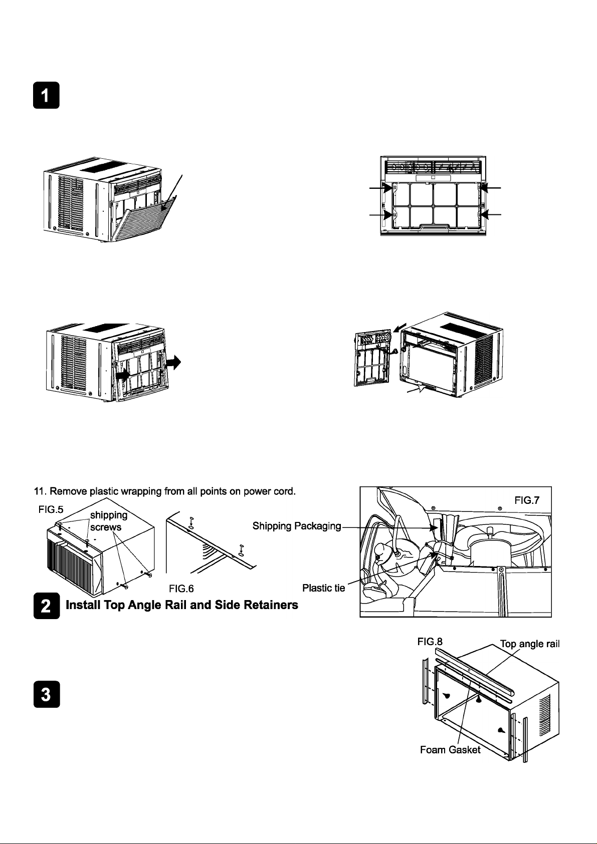
1. Pull down on front grille from upper edge. Lift front grille upwards and place to one side. (See FIG.1)
2. Remove filter. To remove, grasp in the middle on each side. Bow filter out to detach top edge from tabs. Once top
is free, lift filter up and out. PIq 2
FIG.1
3. Locate the four Front Panel screws and remove. These screws will be needed to re-install the Front Panel later
(See FIG.2).
4. Push metal cabinet side inward to release plastic tabs on each side of Front Panel (see Fig. 3).
5. Rotate Front Panel up until top tabs are free. Pull panel straight out. When pulling out, front panel will also pull free
from vent control lever. Depress latch on electronics plug (on some models) to disconnect.
6. Remove Front Panel from unit (see Fig. 4).
FIG.3 — FIG.4
Front Grille
base pan handle
7. Remove shipping screws from top of unit and also on both sides by the base if installed. (See FIG.5)
8. With the aid of an assistant, hold the cabinet while pulling on the base pan handle (see FIG. 4), and carefully
remove the air conditioner from cabinet.
9. Add two foam inserts to holes in top of cabinet where shipping screws were removed from. (See FIG.6)
10. Except 22,000BTU model, other heavy duty models (24,000~28,500BTU) come with internal shipping packaging.
THIS PACKAGING AND PLASTIC TIES MUST BE REMOVED PRIOR TO INSTALLING THE AIR CONDITIONER
BACK INTO THE CABINET. (See FIG.7)
1. Remove adhesive strip coating from foam gasket. Attach adhesive side of gasket to bottom of top angle rail. Insert 4
screws from inside of cabinet and secure to top angle rail.
2. From inside of cabinet insert 3 screws to attach each side retainer as shown
in Fig. 8. Attach side retainers with flat side against cabinet and angled edge toward
rear of cabinet.
Assemble Window Filler Panels
1. Place cabinet on floor, a bench, or a table.
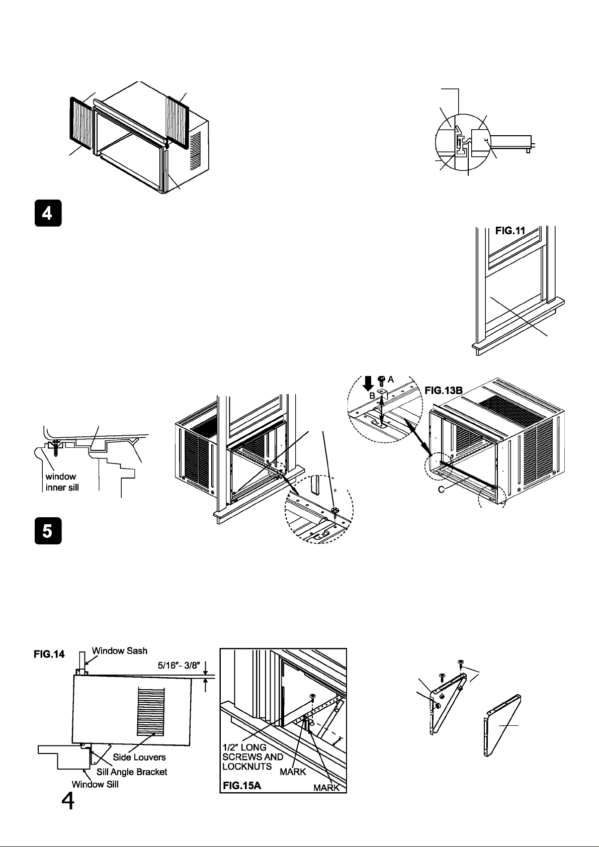
2. Slide T section at end of window filler panel into side retainer on each side of the
cabinet (see FIG. 9 and FIG.10).
3. On each side of cabinet, insert top and bottom legs of window filler panel
frame into channel in the top and bottom angle rails.
4. Insert a 7/16" locking screw and flat washer into hole on top leg of each window filler panel (see section 6). Do not
totally tighten. Allow leg to slide freely. Screws will be tightened after Section 6. ^
Page 4
Installation Instructions
FIG.9 Top window filler
panel leg
Bottom window
filler panel leg
WINDOW FILLER
PANEL
'SIDE RETAINER
FIG.10
TOP VIEW
AIRCONDITIONER
CABINET
T SECTION
WINDOW
FILLER
PANEL
Place Cabinet in Window
1. Open window and mark the center of window inner sill as shown (FIG. 11).
2. Place cabinet in window with cabinet bracket secureiy seated over edge of inner sili as shown
in FIG. 12. Bring window down temporarily behind top angie rail to hold cabinet in piace.
3. Shift cabinet left or right as needed to line up center of cabinet on center iine marked on inner
siil.
4. For wooden window: Fasten cabinet to window inner sill with two 1/2" iong hex head screws
into hoies (FIG.13A). (You may wish to pre-drill pilot holes.)
For Vinyl-Clad window: Place two safety locks into the holes located in the bottom of
the cabinet and drive two #10X1/4" pan-head Phillips locking screws through the safety locks
into the cabinet as shown (FIG.13B).
5. Remove protective strip from adhesive side of Bottom Rail Foam Seal.
Apply Seal over screws fastening bottom rail to window inner sill.
FIG.13A
FIG.12
Angle of cabinet
bracket securely seated
on edge of inner sill.
1/2" long
HEX-HEAD
SCREW
------
PLASTIC
FRAME
LOCKING
SCREW HOLE
cabinet
Bracket
window
outer sill
A. #10 X 1/4" pan-head Phillips screws
Install Support Bracket
B. Safety Lock (Only for Vinly-Clad Window)
C. Bottom Rail Foam Seal
1. IHold each support bracket flush against outside of sill and tight to bottom of cabinet. Mark brackets at top level of
sill. Mark cabinet bottom at distance of sill width. See Fig. 15 A. Remove support brackets.
2. Attach sill angle brackets to support brackets at marked positions with flat head bolts and nuts. Hand tighten only
at this point. See Fig. 15B.
3. Insert 1/2" long bolts through appropriate holes in cabinet bottom given the sill width distance. Thread the bolts into
the slots of the support brackets. Tighten lock washer nuts onto bolts.
4. Adjust height of sill angle bracket so that bracket rests securely on edge of sill, and so that cabinet has the correct
5/8" to 3/8" downward tilt for proper water drainage (see Fig. 14). Tighten nuts securely.
FIG.15B
LEFT
LOCKNUT
SILL ANGLE
BRACKET
FLAT HEAD BOLT
2 EACH REQ’D FOR EACH
SUPPORT BRACKET
1/2" LONG SCREWS
'AND LOCKNUTS
RIGHT
Page 5
Installation Instructions
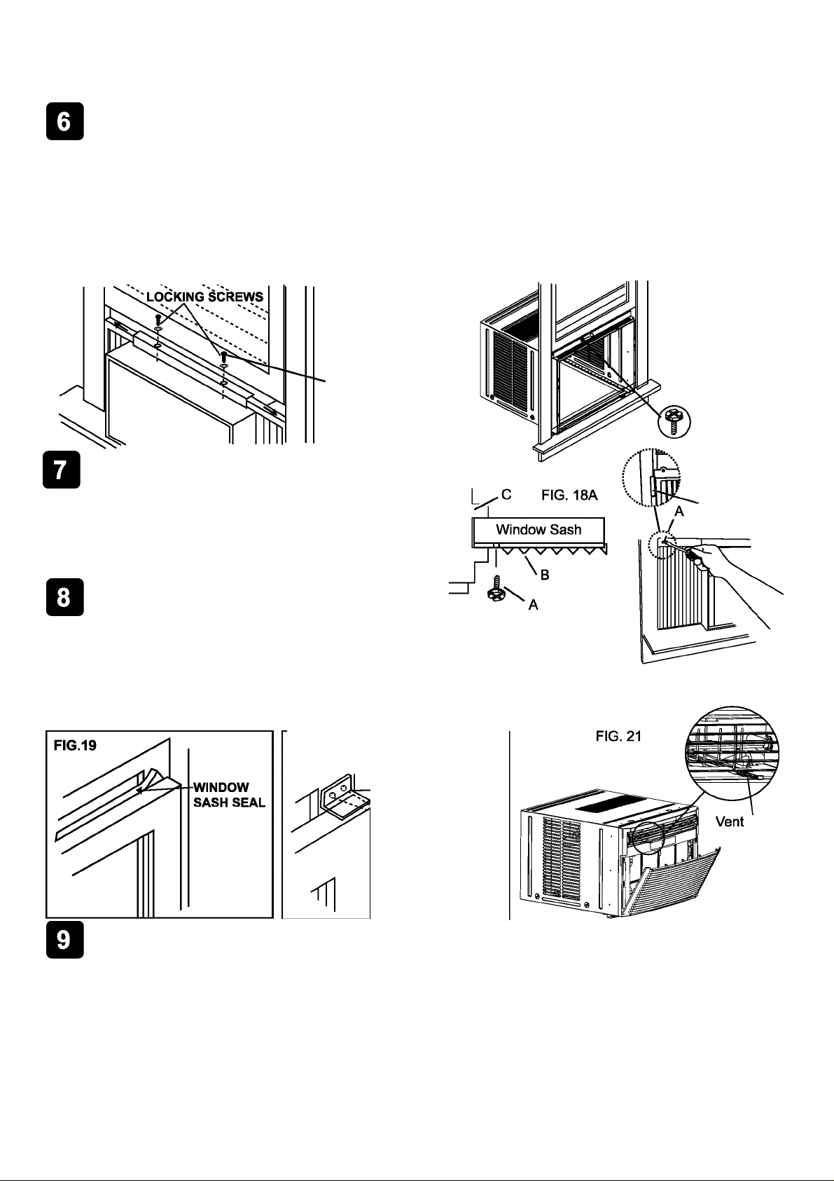
Extend Window Filler Panels and attach to top angle rail:
1. Carefully raise window to expose filler panel locking screws on top angle rail. Loosen screws so filler panels slide
easiiy.
2. Extend panels to fill window opening completely. Tighten locking screws on top (FIG. 16).
3. Close window behind top angle rail.
4. Attach the top angle rail to window frame: Use a 3/32" drill bit to drill one hole through the hole in the middle of top
angle rail into the window frame, and drive one 1/2" HEX-HEAD locking screw through the hole in the middle of top
angle rail into the window frame as shown (FIG. 17).
FIG.16 FIG. 17
7/16" Locking Screw
and Washer
Attach Window Filler Panels to Window Frame
1. Extend the window filler panels out against the window frame.
2. Use a 1/8" drill bit to drill a starter hole through the hole in the
top leg of each window filler panel and into the window sash
(Fig. 18A and Fig. 18B). Connect with one 10x1/2" screw.
Install Window Sash Seal and Safety Lock
1. Trim window sash seal to fit window width. Insert it into
space between upper and lower sashes as shown (FIG. 19).
2. Attach right angle safety lock to top window sash as
shown (FIG.20).
3. If necessary, trim weather seals to needed length, peel
off protective backing, and use to plug any gaps. See Fig. 18B.
FIG.20
SAFETY LOCK
A. #10X1/2" round-head
screw
B. left-hand Window Filler
Panel Top Leg
C. Window channel
1/2" long
-hex-head
screws
1/2" long
HEX-HEAD
SCREW
FIG. 18B
weather seals
A. #10X1/2" round-head
screw
control
correct location
Install Air Conditioner into Cabinet and Install Front Panel to Unit
1. Lift air conditioner and carefully slide into cabinet.
2. CAUTION: Do not push on controls OR finned colls.
3. Be sure air conditioner is firmly seated towards rear of cabinet.
4. Reconnect electronics plug if present. Position vent control lever so that it will thread into its channel in the front
panel (see FIG.21). Hook front panel top tabs into slots on cabinet top, and rotate front panel down so that side tabs
snap into place on cabinet. Insert 4 previously removed screws through front panel and into air conditioner.
5. Insert air conditioner filter. Reinstall the front grille by hooking bottom tabs into slots on Front Panel bottom, then
rotating grille up to snap into place.
Page 6
Installation Instructions
Thru-The-Wall Installation
^ NOTE:
• Consult local building codes prior to installation, or a qualified carpenter.
Select Wall Location
This air conditioner siides out from its cabinet, so that it can be instaiied through an outside wali as expiained
below.
Heavy duty Medium
Max wall thickness 10" 8"
NOTE:
IMPORTANT: Side louvers must never be blocked.
All parts needed for Thru-The-Wall Installation are provided, except a wood frame, shims, and 10 wood screws
(#10-1" long minimum). Select a wall surface that:
1. Does not support major structural loads such as the frame construction at ends of windows, and under
truss-bearing points, etc.
2. Does not have plumbing or wiring inside.
3. Is near existing electrical outlets, or where another outlet can be Installed.
4. Faces to the area to be cooled, and it is not blocked.
5. Allows unblocked airflow from rear sides and end (outside) of installed air conditioner.
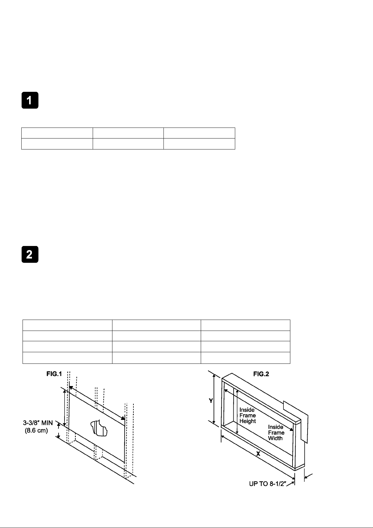
Prepare Wall
1. Prepare wall in frame construction (including brick and stucco veneer). Working from inside the room, find wall stud
nearest the center of area where air conditioner will be installed (by sounding wall, or by magnetically finding nails).
2. Cut out a hole on each side of center stud.
3. Measure between inside edges of every other stud as shown in FIG.1. Carefully measure and cut an opening with
the following dimensions depending on your model. See FIG.1 and FIG.2.
WIDTH “X” = inside model width plus twice the thickness of framing material used.
HEIGHT “Y” = inside model height plus twice the thickness of framing material used.
Heavy Duty Medium
Capacity:
Inside Frame Height: 18-7/8" (47.9 cm) 18" (45.7 cm)
Inside Frame Width:
22,000~28,500BTU
26-3/4" (67.9 cm)
15,000-18,500BTU
23-7/8" (60.6 cm)
Page 7
Installation Instructions
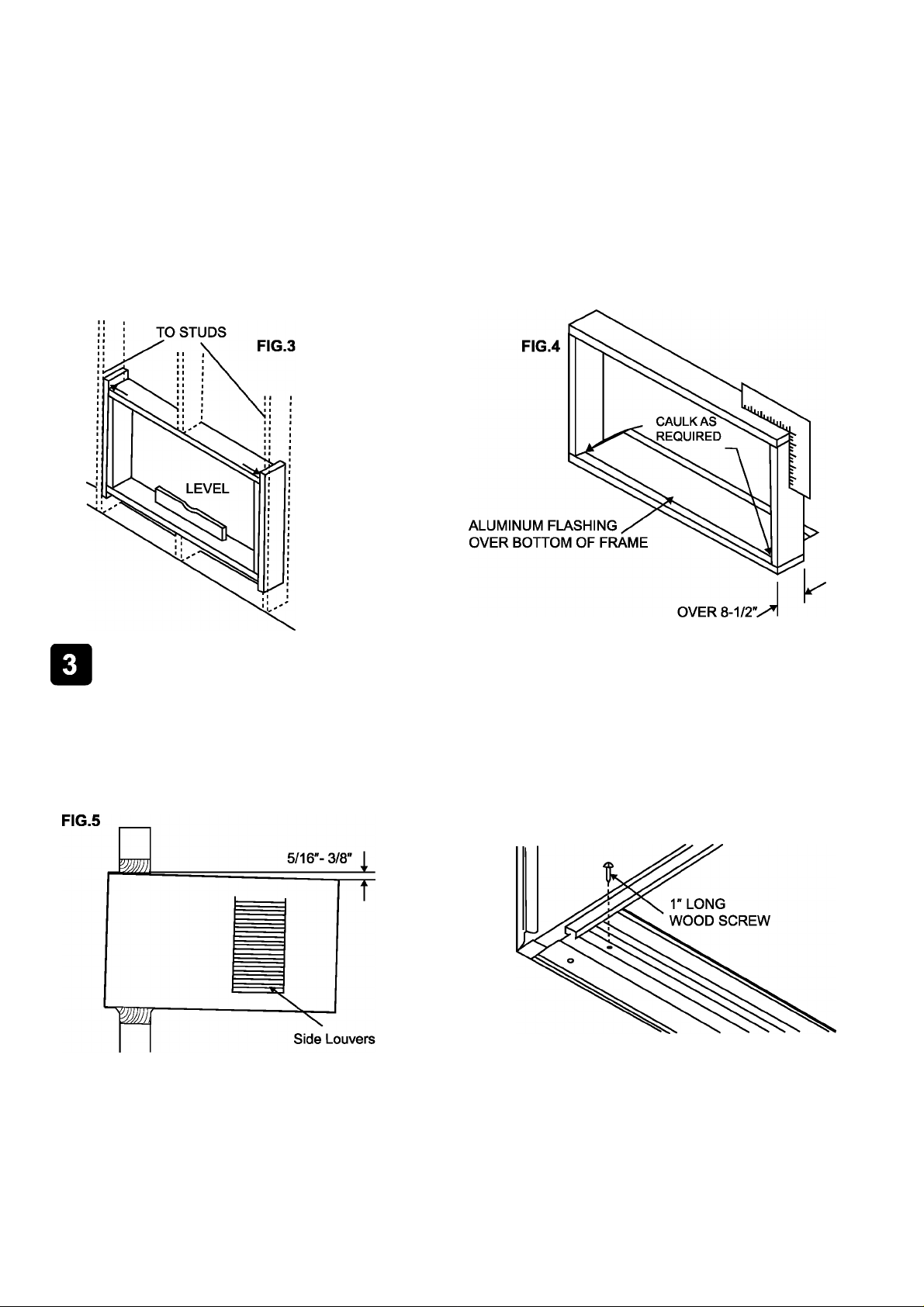
4. Build a wooden frame with the INSIDE dimensions of your model listed above. (Measure twice remember...) Frame
depth should be the same as wall thickness. Fill in the space from the opending to the studs with wood spacers, as
shown.
5. Nail frame to spacers to spacers with front flush with dry wall.
^ NOTE:
• If wall thickness is 8-1/2” or more, add alumimum flashing over bottom of frame opening to assure no water can
enter area between inner and outer wall.
NAIL SPACERS
Prepare and Install Cabinet
1. Slide air conditioner from cabinet; refer back to Step 1 of Window Mounting.
2. Place cabinet into opening with bottom rail resting firmly on bottom board of wooden frame.
3. Position cabinet to achieve proper downward tilt for water removal. Unit must tilt back 5/16" to 3/8" for proper water
drainage. (See FIG.5 below.)
4. Secure bottom rail to wood frame with two large wood screws 1" (2.5 cm) long using the two holes In the bottom of
the channel resting on frame. (See FIG.6 following)
FIG.6
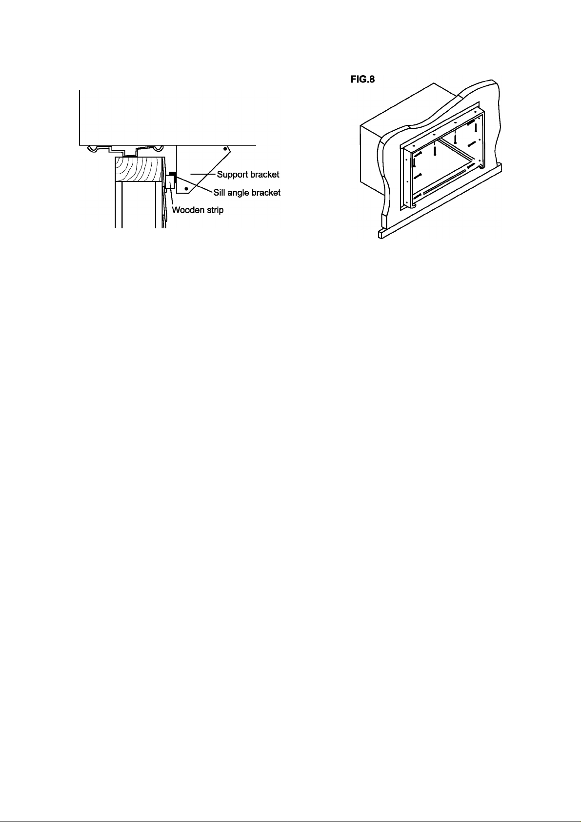
Refer to Step 5 of Window Mounting for assembly of support brackets. Nall a wooden strip to the outside wall for the
angle sill bracket to rest upon. See Fig. 7.
5. Screw or nail cabinet to wooden frame using shims as needed to eliminate cabinet distortion. See Fig. 8. Remember
to maintain proper tilt as described In Step 3.
Page 8
Installation Instructions
FIG.7
6. Install air conditioner into cabinet by following all steps in Step 9 of Window Mounting.
OPTiONAL: Caulking and instaliation of trim on interior wall may be done. You can buy wood from your local lumber or
hardware supply. On the outside, cauik opendings around top and sides of cabinet, and all sides of wood sleeve to the
opening.
NOTE:
• See Step 5, Item 4 of Window Mounting Instructions for bottom rail seal location.
Masonry Construction
1. Cut or build a wall opening in the masonry wall similar to the frame construction (refer to Step 2 of Thru-the-Wall
Installation for a wail thickness greater than 8-1/2").
2. Secure cabinet in place using masonry nails, or the right masonry anchor screws. (Another way to secure cabinet is
to buiid a frame in the masonry waii such as the one shown in Fig. 3 of Step 2 Prepare Wali. Securely anchor frame to
masonry wall. This way gives very good louver clearance on either side of cabinet.)
3. Install a lintel to support masonry wall above cabinet. Existing holes in cabinet can be used and/or additions holes
can be drilled to fasten cabinet at various positions. Be sure that side louver clearance is in accordance with Step 1
Select Wall Location.
4. Install exterior cabinet support brackets as shown in Step 3 of Thru-the-Wall Installation. Caulk or flash if needed, to
provide a weather-tight seal around top and sides of cabinet.
5. To complete installation, apply wood trim molding around room side projection of cabinet.
8
 Loading...