

GAS COOKTOP INSTALLATION INSTRUCTIONS
(For Models with 4 Sealed Burners, Tempered Glass Cooktops or Porcelain Enamel Cooktops)
INSTALLATION AND SERVICE MUST BE PERFORMED BY
A QUALIFIED INSTALLER.
IMPORTANT: SAVE FOR LOCAL ELECTRICAL INSPECTOR'S USE.
READ AND SAVE THESE INSTRUCTIONS FOR FUTURE REFERENCE.
If the information in this manual is not followed exactly, a fire or explosion may result
causing property damage, personal injury or death.
FOR YOUR SAFETY:
— Do not store or use gasoline or other flammable vapors and liquids in the vicinity of this or any
other appliance.
— WHAT TO DO IF YOU SMELL GAS:
• Do not try to light any appliance.
• Do not touch any electrical switch; do not use any phone in your building.
• Immediately call your gas supplier from a neighbor's phone. Follow the gas supplier's
instructions.
• If you cannot reach your gas supplier, call the fire department.
— Installation and service must be performed by a qualified installer, service agency or the gas
supplier.
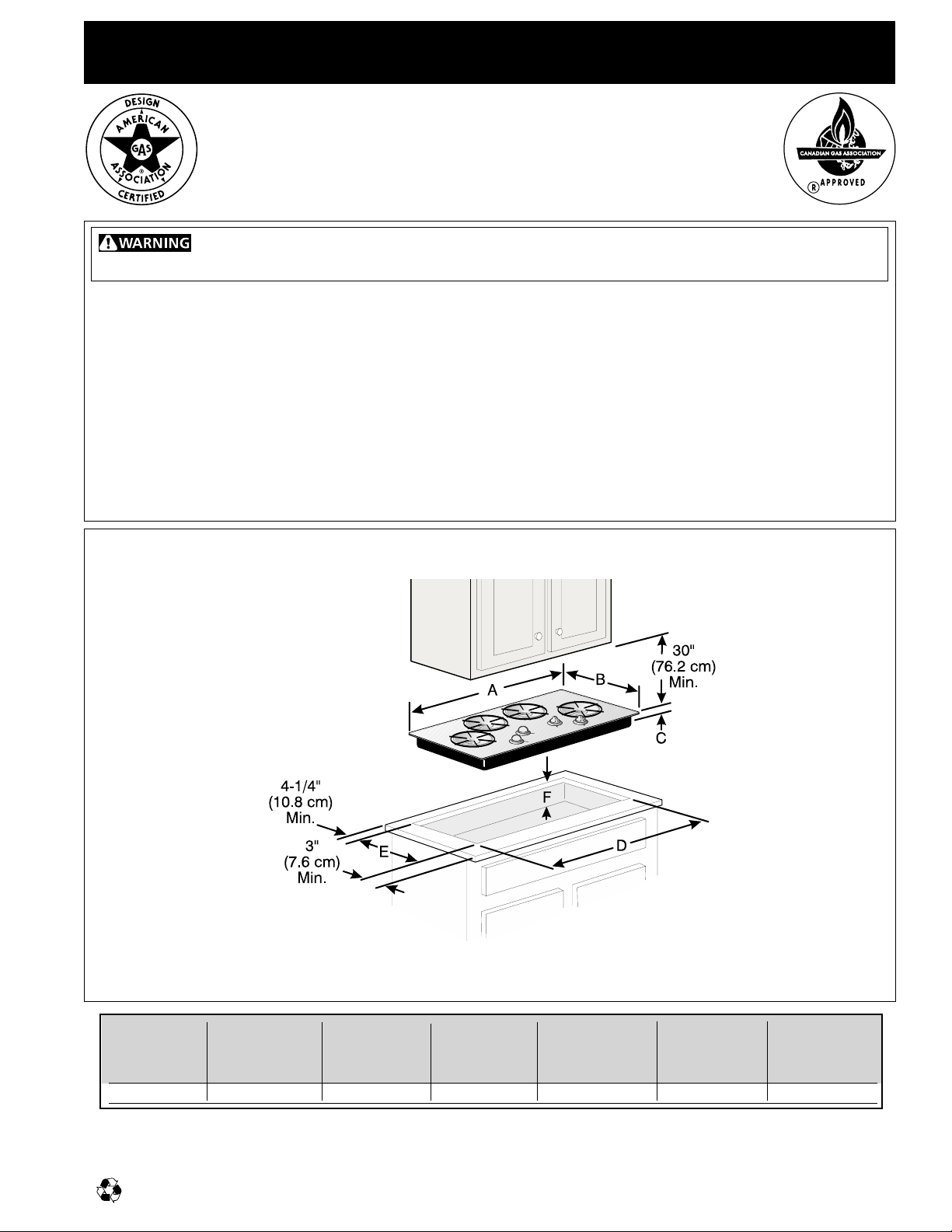
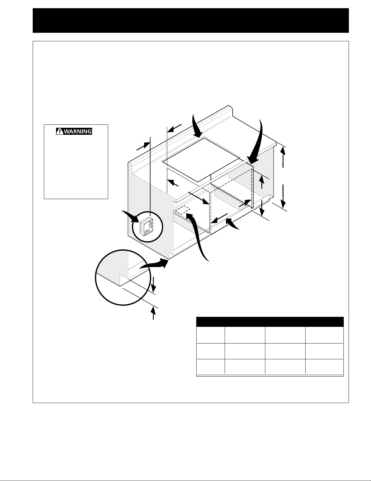
Cooktop and Cutout Dimensions
Figure 1
*
* 30" (76.2 cm) min. for
unprotected cabinet
24" (61 cm) min. for
protected surface
CUTOUT CUTOUT F. DEPTH
MODEL A. LENGTH B. WIDTH C. DEPTH DIMENSIONS DIMENSIONS BELOW
D. LENGTH E. WIDTH COOKTOP*
5
36" Cooktop 36 (91.5 cm) 18 (45.7 cm) 3
* Includes a 5" (12.7 cm) space underneath the cooktop for connection to gas supply line.
Recycled paper Printed in Canada P/N 318063905 (9604) Rev. A
/
32
(8 cm) 34
1
1
/
4
(8.7 cm) 16
3
/
4
(42.5 cm) 8
1
/
4
(21 cm)
GAS COOKTOP INSTALLATION INSTRUCTIONS
(For Models with 4 Sealed Burners, Tempered Glass Cooktops or Porcelain Enamel Cooktops)
Important Notes to the Installer
1. Read all instructions contained in these installation
instructions before installing the cooktop.
2. Remove all packing material before connecting the
electrical supply to the cooktop.
3. Observe all governing codes and ordinances.
4. Be sure to leave these instructions with the consumer.
Important Note to the Consumer
Keep these instructions with your owner's guide for future
reference.
IMPORTANT SAFETY
INSTRUCTIONS
Installation of this cooktop must conform with local
codes or, in the absence of local codes, with the National
Fuel Gas Code ANSI Z223.1—latest edition, or with the
Canadian Fuel Gas Code, CAN/CGA B149 and CAN/CGA
B149.2.
This cooktop has been design certified by the American
Gas Association. As with any appliance using gas and
generating heat, there are certain safety precautions you
should follow. You will find them in the Owner's Guide,
read it carefully.
• Do not store or use gasoline or other flammable
vapors and liquids near this or any other
appliance. Explosions or fires could result.
The electrical power to the cooktop
must be shut off while line connections are being
made. Failure to do so could result in serious injury
or death.
This cooktop is not approved for use
with downdraft systems.
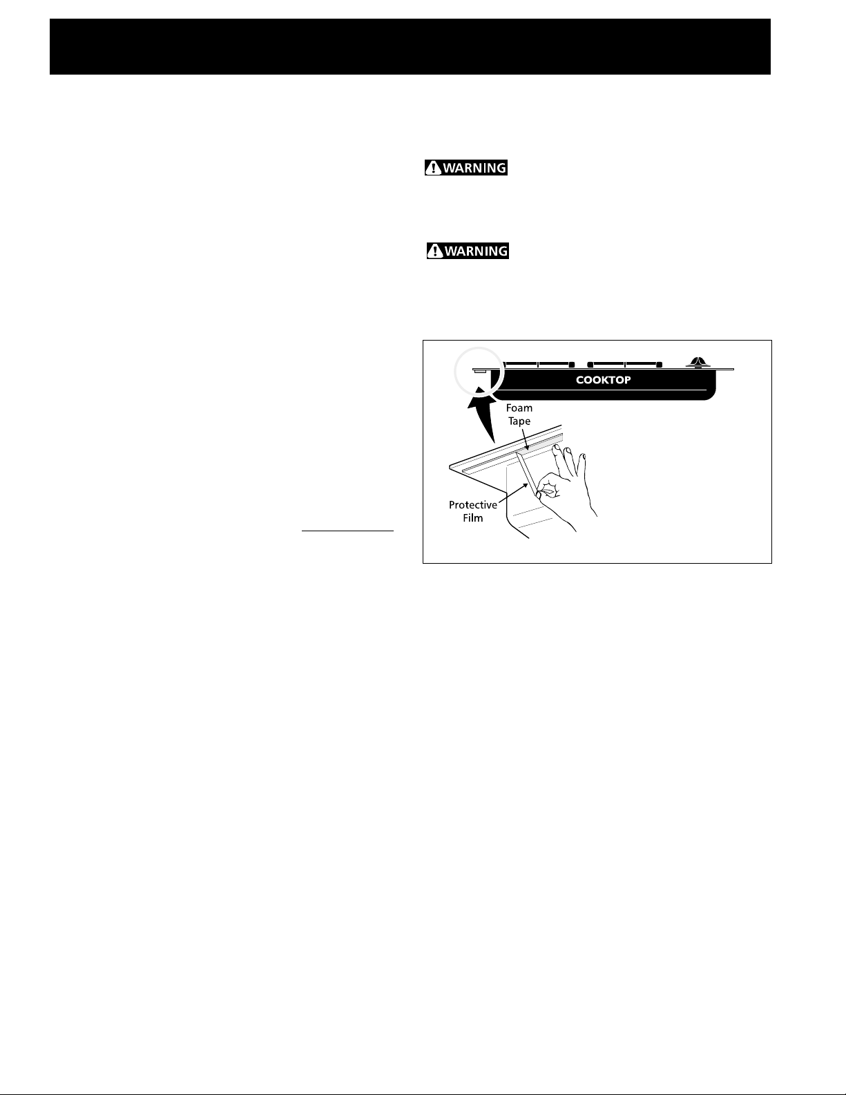
Before Installing the Cooktop
(Gas on Glass Models Only)
Figure 2
• Be sure your cooktop is installed and grounded
properly by a qualified installer or service
technician.
• This cooktop must be electrically grounded in
accordance with local codes or, in their absence,
with the National Electrical Code ANSI/NFPA No.
70—latest edition, or with the Canadian Electrical
Code, CSA C22.1 Part 1.
• The burners can be lit manually during an
electrical power outage. To light a burner, hold a
lit match to the burner head, then slowly turn the
Surface Control knob to LITE. Use caution when
lighting burners manually.
• Do not store items of interest to children in the
cabinets above the cooktop. Children could be
seriously burned climbing on the cooktop to reach
items.
• To eliminate the need to reach over the surface
burners, cabinet storage space above the burners
should be avoided.
• Adjust surface burner flame size so it does not
extend beyond the edge of the cooking utensil.
Excessive flame is hazardous.
• Never use your cooktop for warming or heating
the room. Prolonged use of the cooktop without
adequate ventilation can be hazardous.
A roll of foam tape is supplied in the literature package.
Install the foam tape around the perimeter of the flange
of the burner box, at a distance of 1/4" from the edge of
the glass. Apply the exposed adhesive side of the tape
against the underside of the glass surface (see Figure 2).
Remove the protective film from the underside of the
foam tape before inserting the cooktop into the
countertop opening.
NOTE: This tape seals the underside of the cooktop to
the counter. Do not remove this foam tape. This tape
prevents entry of air for normal gas combustion, and
prevents liquids from leaking under the cooktop.
After inserting the cooktop into the countertop opening,
make sure the unit is sitting on the metal flange around
the top of the burner box. The cooktop must not sit
on the glass top. Avoid cutting an oversized hole in the
countertop to prevent glass top from sitting on the
countertop.
2
GAS COOKTOP INSTALLATION INSTRUCTIONS
(For Models with 4 Sealed Burners, Tempered Glass Cooktops or Porcelain Enamel Cooktops)
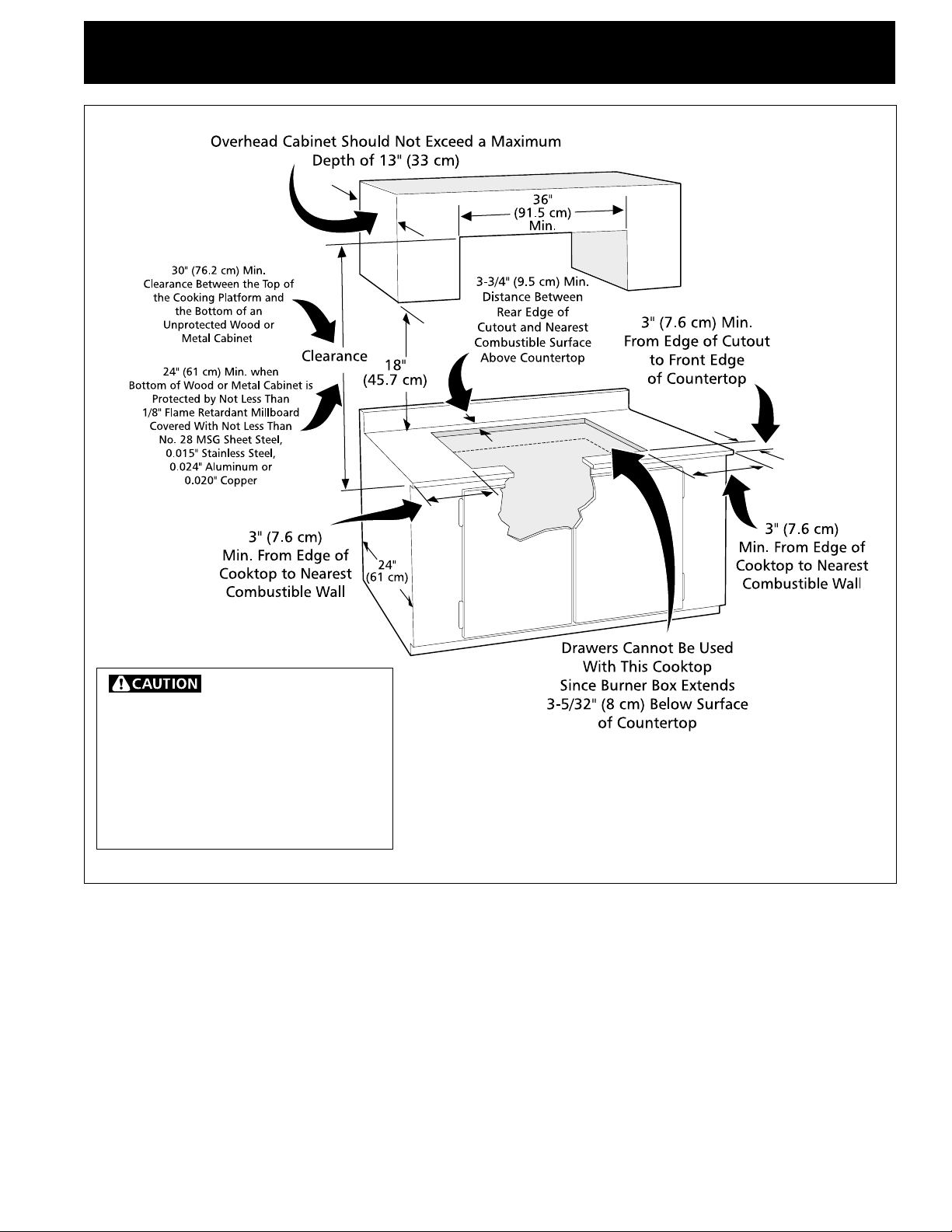
To eliminate the risk of
burns or fire by reaching over heated
surfaces, cabinet storage space located
above the cooktop should be avoided. If
cabinet storage is provided, risk can be
reduced by installing a range hood that
projects horizontally a minimum of 5"
(10.2 cm) beyond the bottom of the
cabinets.
Figure 3 – CABINET DESIGN
3
GAS COOKTOP INSTALLATION INSTRUCTIONS
(For Models with 4 Sealed Burners, Tempered Glass Cooktops or Porcelain Enamel Cooktops)
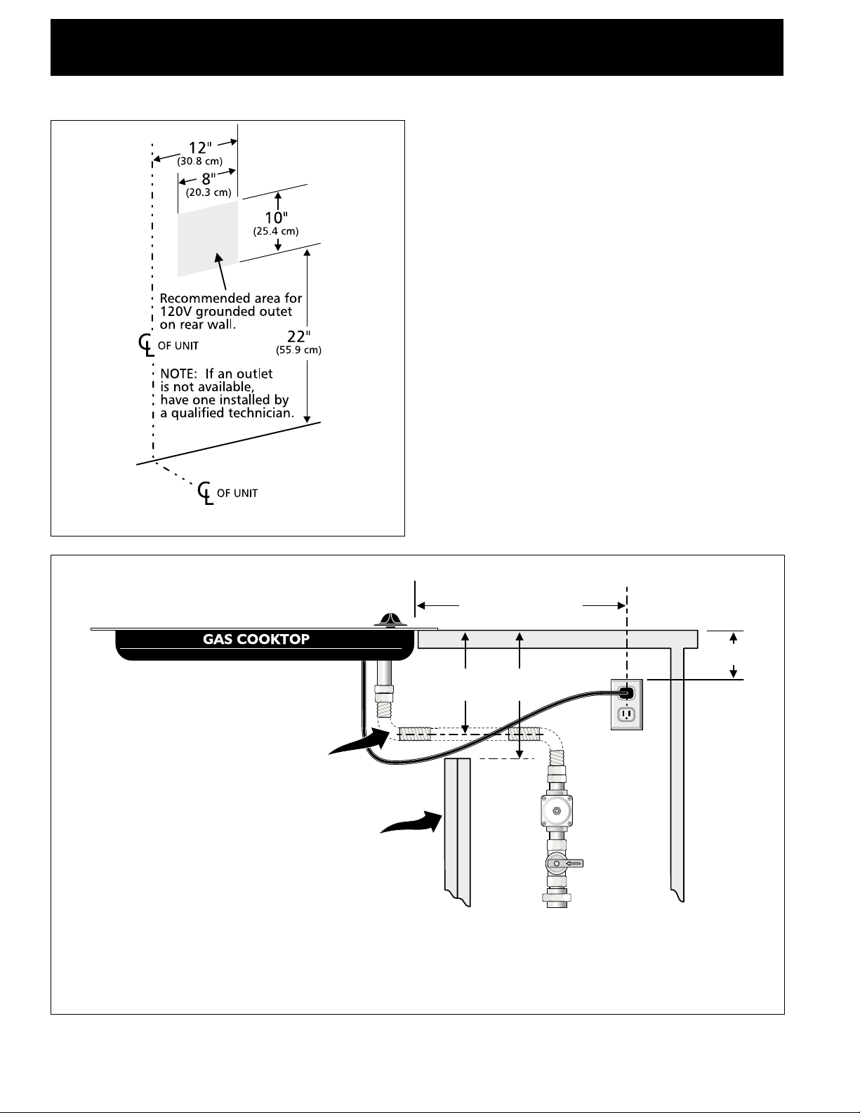
Wall Outlet Location
Wall Oven
Cabinet
Figure 4
Flexible Appliance Conduit
Cabinet sides or
filler panel
5" (12.7 cm)
Max.
Flare Union
18" (45.7 cm) Max.
6 1/2"
(16.5 cm) Min.
Flare
Union
120V/60Hz
Grounded
Outlet
Pressure
Regulator
Manual
Shutoff
Valve
4" (10.2 cm)
Right Side
of Cabinet
(To be
accessible
for shutoff valve
operation)
Figure 5 – TYPICAL GAS COOKTOP INSTALLATION
OVER AN ELECTRIC BUILT-IN OVEN INSTALLED UNDER THE COUNTER
(THE COOKTOP SHOWN IS A GAS ON GLASS MODEL)
4
GAS COOKTOP INSTALLATION INSTRUCTIONS
(For Models with 4 Sealed Burners, Tempered Glass Cooktops or Porcelain Enamel Cooktops)
Side filler panels are necessary to
isolate the unit from adjoining
Only certain cooktop models may be installed over
certain built-in electric oven models, listed by the
MFG ID number (see the insert sheet included in
the literature package). For detailed installation,
see the Installation Instructions on the preceding
pages.
T o r educe the risk of
personal injury and
tipping the wall
oven, the wall oven
must be secured to
the cabinet(s) by
properly installed
anti-tip screws.
Approx. 3"
(7.6 cm)
G
cabinets. Panel height should allow
for installation of approved cooktop
models. See "Typical Gas Cooktop
Installation Over an Electric Built-in
Oven Installed Under the Counter"
on the preceding page.
36" Min.
(91.4 cm)
E
208/240V junction box for
built-in oven.
4 1/2"
(11.4 cm)
Max.*
* If no cooktop is installed directly over the oven
unit, 5" (12.7 cm) maximum is allowed.
F
Use 3/4" (1.9 cm) plywood, installed
on two runners, flush with toe plate.
Must be capable of supporting 150
lbs (68 kg).
Cut an opening in wood base
minimum 9" x 9", 2" (23 x 23, 5 cm)
from left side filler panel, to route
armoured cable to junction box or
fuse box.
CUTOUT DIMENSIONS
Wall Oven E. F. G.
Size HEIGHT WIDTH DEPTH
30" 28
27" 28
1
/
4" - 28
7
/
8" 28
1
/
2" - 29" 24"
(71.8 - 73.3 cm) (72.4 - 73.7 cm) (61 cm)
1
/
8" - 28
7
/
8" 24
7
/
8" - 25
1
/
4" 23
(71.4 - 73.3 cm) (63.2 - 64.1 cm) (59.7 cm)
1
/
2"
Figure 6 – TYPICAL UNDER COUNTER INSTALLATION OF AN ELECTRIC BUILT-IN OVEN
WITH A COOKTOP MOUNTED ABOVE
5
GAS COOKTOP INSTALLATION INSTRUCTIONS
(For Models with 4 Sealed Burners, Tempered Glass Cooktops or Porcelain Enamel Cooktops)
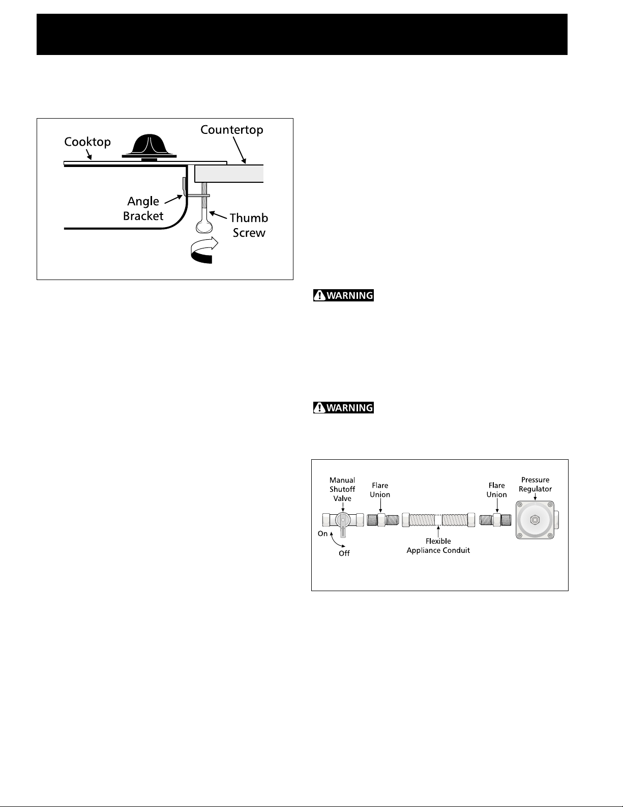
Clamp Down Information
Once the unit is installed in the counter opening, you
must clamp the unit down as shown.
Figure 7
To clamp down, insert the bracket with the offset side of
the angle into the slots on each side of the unit. The
thumb screw should then be run through the bracket, up
against the bottom of the counter. Tighten until the unit
draws down.
Provide an Adequate Gas Supply
When shipped from the factory, this unit is designed to
operate on 4" water column (1.0 kPa) Natural gas
manifold pressure. A convertible pressure regulator is
connected to the manifold and MUST be connected in
series with the gas supply line.
For proper operation, the maximum inlet pressure to
the regulator should be no more than 14" of water
column pressure (3.5 kPa).
LP/Propane Gas Conversion
This appliance can be used with Natural gas or LP/
Propane gas. It is shipped from the factory for use with
natural gas.
If you wish to convert your cooktop for use with LP/
Propane gas, use the supplied fixed orifices located in
the package containing the Installation Instructions, in a
bag marked, "FOR LP/PROPANE GAS CONVERSION."
Follow the instructions packaged with the orifices.
The conversion must be performed by a qualified service
technician in accordance with the manufacturer's
instructions and all local codes and requirements. Failure
to follow these instructions could result in serious injury
or property damage. The qualified agency performing
this work assumes responsibility for the conversion.
Failure to make the appropriate
conversion can result in personal injury and property
damage.
Install Pressure Regulator
Install the pressure regulator with the arrow on the
regulator pointing up toward the unit in a position
where you can reach the access cap.
Do not make the connection too tight.
The regulator is die cast. Overtightening may crack the
regulator resulting in a gas leak and possible fire or
explosion.
The inlet pressure to the regulator must be at least 1"
(.25 kPa) greater than the regulator manifold pressure
setting. The regulator is set for 4" water column (1.0
kPa) Natural gas manifold pressure, the inlet pressure
must be at least 5" water column (1.25 kPa) Natural gas.
For LP/Propane gas, the regulator must be set for 10"
water column (2.5 kPa) manifold pressure, the inlet
pressure must be at least 11" water column (2.75 kPa).
The gas supply line to the range should be 1/2" or 3/4"
solid pipe.
Figure 8
Assemble the flexible connector from the gas supply pipe
to the pressure regulator in order: manual shutoff valve,
nipple, flare union adapter, flexible connector, flare
union adapter, nipple, pressure regulator.
Use pipe-joint compound made for use with Natural and
LP/Propane gas to seal all gas connections. If flexible
connectors are used, be certain connectors are not
kinked.
6
 Loading...