

Page 1
40" DUAL FUEL RANGE INSTALLATION INSTRUCTIONS
INSTALLATION INSTRUCTIONS
40" DUAL FUEL RANGE
INSTALLATION AND SERVICE MUST BE PERFORMED BY A QUALIFIED INSTALLER.
IMPORTANT: SAVE FOR LOCAL ELECTRICAL INSPECTOR'S USE.
READ AND SAVE THESE INSTRUCTIONS FOR FUTURE REFERENCE.
United States
FOR YOUR SAFETY: Do not store or use
gasoline or other ammable vapors and liquids in the
vicinity of this or any other appliance.
Table of Contents
Important Safety Instructions .......................................2-4
Product Dimensions ....................................................... 5
Cabinet Dimensions ....................................................... 6
Cabinet Construction ...................................................... 7
Electrical Requirements...............................................7-8
Power Supply Cord......................................................... 8
Fuel Supply Requirements ............................................. 9
Canada
Connect Fuel Supply .................................................... 10
Install Oven Racks.........................................................11
Level the Range ............................................................11
Install Anti-Tip Bracket ............................................. 12-13
Prepare Burner Assemblies ..................................... 14-15
Check Oven Operation ................................................. 15
After Installation ............................................................ 16
Serial Plate Location (Model & Serial Number) ............ 16
Important Notes to the Installer
1. Read all instructions contained in these installation
instructions before installing range.
2. Remove all packing material from the oven and the
drawer compartments before connecting the electrical
supply to the range.
3. The anti-tip bracket supplied with the appliance must
be installed.
4. Observe all governing codes and ordinances.
5. Be sure to leave these instructions with the consumer.
Printed in the United States
Important Note to the Consumer
1. Keep these instructions with your owner's guide for
future reference.
2. When using any appliance generating heat, there are
safety precautions you must follow. These precautions
are explained in your Use and Care manual. Read
your manual carefully.
3. Be sure your appliance is installed and grounded by a
qualied installer or service technician.
P/N 809019101 (1701) Rev.A
English – pages 1-16
Español – pages 17-32
Français – pages 33-48
1
Page 2
40" DUAL FUEL RANGE INSTALLATION INSTRUCTIONS
IMPORTANT SAFETY INSTRUCTIONS
This appliance must be installed, grounded, and serviced by a qualied installer or service technician.
This manual contains important safety symbols and instructions. Please pay attention to these symbols and follow all
instructions given. Do not attempt to install or operate your appliance until you have read the safety precautions in this
manual. Safety items throughout this manual are labeled with a WARNING or CAUTION statement based on the risk type.
Warnings and important instructions appearing in this guide are not meant to cover all possible conditions and situations
that may occur. Common sense, caution, and care must be exercised with installing, maintaining, or operating your
appliance.
This is the safety alert symbol. It is used to alert you to potential personal injury hazards. Obey all safety messages
that follow this symbol to avoid possible injury or death.
Indicates a potentially hazardous situation which, if not avoided, may result in death or serious injury.
Indicates a potentially hazardous situation which, if not avoided, may result in minor or moderate injury.
IMPORTANT: Indicates installation, operation, maintenance, or valuable information that is not hazard related.
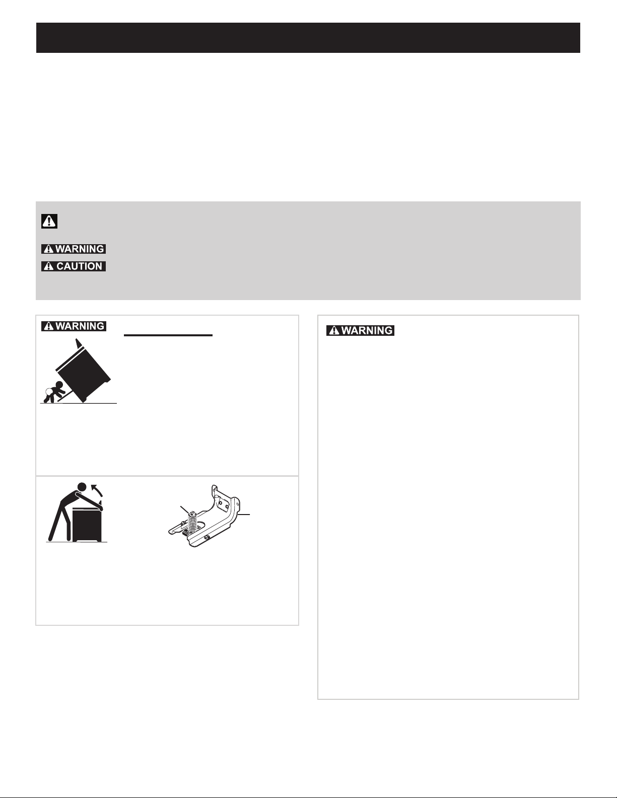
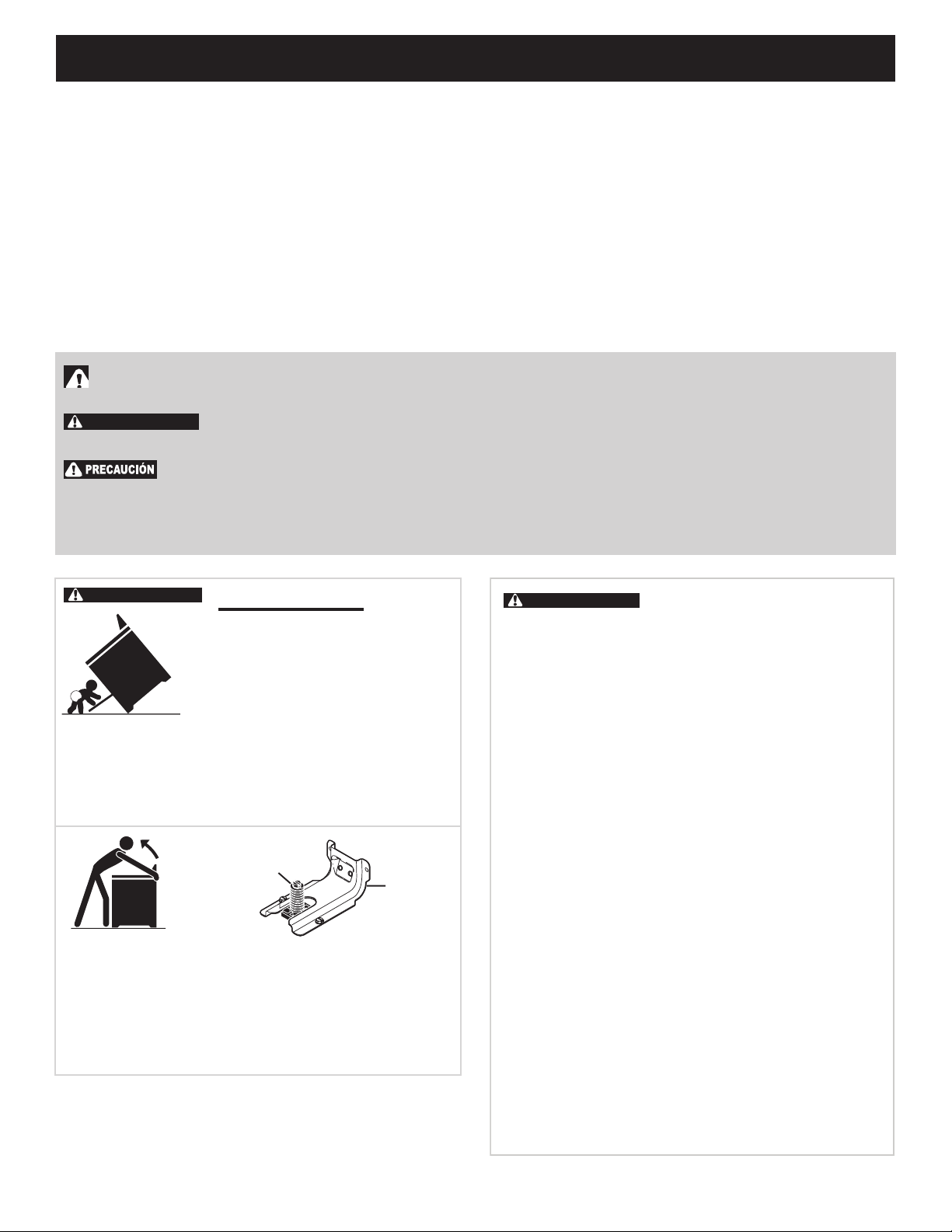
Tip Over Hazard
• A child or adult can tip the range
and be killed.
• Verify the anti-tip device has been
installed to floor or wall.
• Ensure the anti-tip device is re-engaged to floor or wall
when the range is moved.
• Do not operate the range without the anti-tip device in
place and engaged.
• Failure to follow these instructions can result in death or
serious burns to children and adults.
Range
leveling leg
Anti-tip
bracket
To check if the anti-tip bracket is installed properly, use both
arms to grasp the rear edge of the range back. Carefully
attempt to tilt range forward. When properly installed, the range
should not tilt forward.
Refer to the anti-tip bracket installation instructions supplied
with your range for proper installation.
If the information in this manual
is not followed exactly, a fire or explosion
may result causing property damage,
personal injury or death.
FOR YOUR SAFETY:
—Do not store or use gasoline or other
flammable vapors and liquids in the
vicinity of this or any other appliance.
—WHAT TO DO IF YOU SMELL GAS:
•Do not try to light any appliance.
•Do not touch any electrical switch; do
not use any phone in your building.
•Immediately call your gas supplier from
a neighbor's phone. Follow the gas
supplier's instructions.
•If you cannot reach your gas supplier,
call the fire department.
—Installation and service must be
performed by a qualified installer,
servicer or the gas supplier.
2
Page 3
40" DUAL FUEL RANGE INSTALLATION INSTRUCTIONS
• Excessive Weight Hazard--Use two or more
people to move and install range. Failure to follow
this instruction can result in back or other injury.
• Storage In or On Appliance—Flammable
materials should not be stored in an oven or
microwave, near surface burners or elements, or
in the storage or warmer drawer (if equipped). This
includes paper, plastic, and cloth items, such as
cookbooks, plastic ware, and towels, as well as
ammable liquids. Do not store explosives, such as
aerosol cans, on or near the appliance.
• Do not leave children alone - Children should
not be left alone or unattended in the area where
appliance is in use. They should never be allowed
to sit or stand on any part of the appliance,
including the storage drawer, lower broiler drawer,
warmer drawer, or lower double oven.
• Do not store items of interest to children in the
cabinets above the appliance or on the backguards
of ranges. Children climbing on or near the
appliance to reach items could be seriously injured.
• Stepping, leaning, or sitting on the door or drawers
of this appliance can result in serious injuries and
also cause damage to the appliance.
• Do not use oven or warmer drawer (if equipped) for
storage.
• Never use your appliance as a space heater to
heat or warm the room. Doing so may result in
carbon monoxide poisoning and overheating of the
appliance.
• Do not store or use gasoline or other ammable
vapors and liquids in the vicinity of this or any other
appliance.
• Air curtain or other overhead range hoods which
operate by blowing a downward air ow onto a
range or cooktop, shall not be used in conjunction
with gas ranges or cooktops other than when the
range or cooktop and hood have been designed,
tested, and listed by an independent test laboratory
for use in combination with each other.
IMPORTANT INSTRUCTIONS FOR UNPACKING AND
INSTALLATION
Read and follow the below instructions and precautions
for unpacking, installing, and servicing your appliance:
• Destroy the carton and plastic bags after unpacking the
appliance. Never allow children to play with packaging
material. Do not remove the wiring label and other
literature attached to the appliance. Do not remove
model/serial number plate.
• Cold temperatures can damage the electronic control.
When using this appliance for the rst time, or when the
appliance has not been used for an extended period of
time, be sure the appliance has been in temperatures
above 32ºF (0ºC) for at least 3 hours before turning on
the power to the appliance.
• Never modify or alter the construction of the appliance
by removing the leveling legs, panels, wire covers, antitip brackets/screws, or any other part of the appliance.
• Proper Installation—Be sure your appliance is properly
installed and grounded by a qualied technician. In the
United States, install in accordance with the National
Fuel Gas Code ANSI Z223.1/NPFA No. 54, latest
edition and National Electrical Code NFPA No. 70
latest edition, and local electrical code requirements.
In Canada, install in accordance with CAN/CGA
B149.1 and CAN/CGA B149.2 and CSA Standard
C22.1, Canadian Electrical code, Part 1-latest editions
and local electrical code requirements. Install only
per installation instructions provided in the literature
package for this appliance.
• The installation of appliances designed for
manufactured (mobile) home installation must
conform with Manufactured Home Construction and
Safety Standard, title 24CFR, part 3280 [Formerly
the Federal Standard for Mobile Home Construction
and Safety, title 24, HUD (part 280)] or when
such standard is not applicable, the Standard for
Manufactured Home Installation 1982 (Manufactured
Home Sites, Communities and Setups), ANSI Z225.1/
NFPA 501A-latest edition, or with local codes in United
States and with CAN/CSA-Z240 MH in Canada.
• Before installing the range in an area covered with
linoleum or any other synthetic oor covering, make
sure the oor covering can withstand heat at least
90°F (32.2°C) above room temperature without
shrinking, warping or discoloring. Do not install the
range over carpeting unless you place an insulating
pad or sheet of ¼" (0,64 cm) thick plywood between
the range and carpeting.
• Make sure the wall coverings and cabinet materials
around the range can withstand the heat generated by
the appliance.
• To eliminate the risk of burns or re by reaching over
heated surface units, cabinet storage space above the
surface unit should be avoided. If cabinet storage is to
be provided the risk can be reduce by installing a range
hood that projects horizontally a minimum of 5 inches
beyond the bottom of the cabinet.
• Do not obstruct airow at the oven vent, around
the base, or beneath the lower front panel of the
appliance. This appliance requires fresh air for proper
operation.
• Be sure to have an appropriate foam-type re
extinguisher available, visible, and easily accessible
located near the appliance.
3
Page 4
40" DUAL FUEL RANGE INSTALLATION INSTRUCTIONS
SPECIAL INSTRUCTIONS FOR APPLIANCES
INSTALLED IN THE STATE OF MASSACHUSETTS
This appliance can only be installed in the State of
Massachusetts by a Massachusetts licensed plumber or
gas tter. When using a exible gas connector, it must
not exceed 3 feet (36 inches) in length. A "T" handle type
manual gas valve must be installed in the gas supply line
to this appliance.
CONVERSION TO L.P. GAS
This appliance allows for conversion to Liqueed
Petroleum (L.P.) Gas.
Personal injury or death from electrical
shock may occur if the conversion to L.P. gas is not
made by a qualied installer or electrician. Any additions,
changes or conversions required in order for this
appliance to satisfactorily meet the application needs
must be made by a qualied technician.
If L.P. conversion is needed, contact your local L.P.
Gas provider for assistance. The L.P. conversion kit is
provided with this appliance and is located on the lower
REAR (back side) panel of the range. Before installing
the kit be sure to read the L.P. Installation Instructions
and follow them carefully when making the installation.
IMPORTANT INSTRUCTIONS FOR SERVICE AND
MAINTENANCE
• Do not repair or replace any part of the appliance
unless specically recommended in the manuals. All
other servicing should be done only by a qualied
technician. This reduces the risk of personal injury
and damage to the appliance.
• Always contact your dealer, distributor, service agent,
or manufacturer about problems or conditions you do
not understand.
• Ask your dealer to recommend a qualied technician
and an authorized repair service. Know how to
disconnect the power to the appliance at the circuit
breaker or fuse box in case of an emergency.
• Remove the oven door from any unused oven if it is to
be stored or discarded.
• Do not touch a hot oven light bulb with a damp cloth.
Doing so could cause the bulb to break. Handle
halogen lights (if equipped) with paper towels or soft
gloves. Disconnect the appliance or shut off the power
to the appliance before removing and replacing the
bulb.
4
Page 5
40" DUAL FUEL RANGE INSTALLATION INSTRUCTIONS
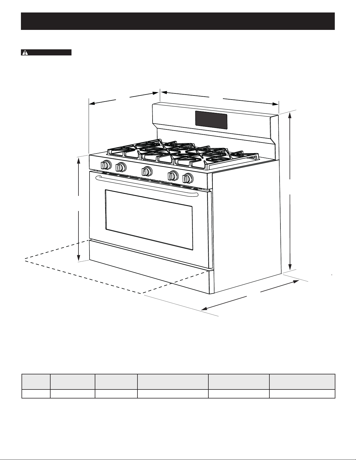
Product Dimensions
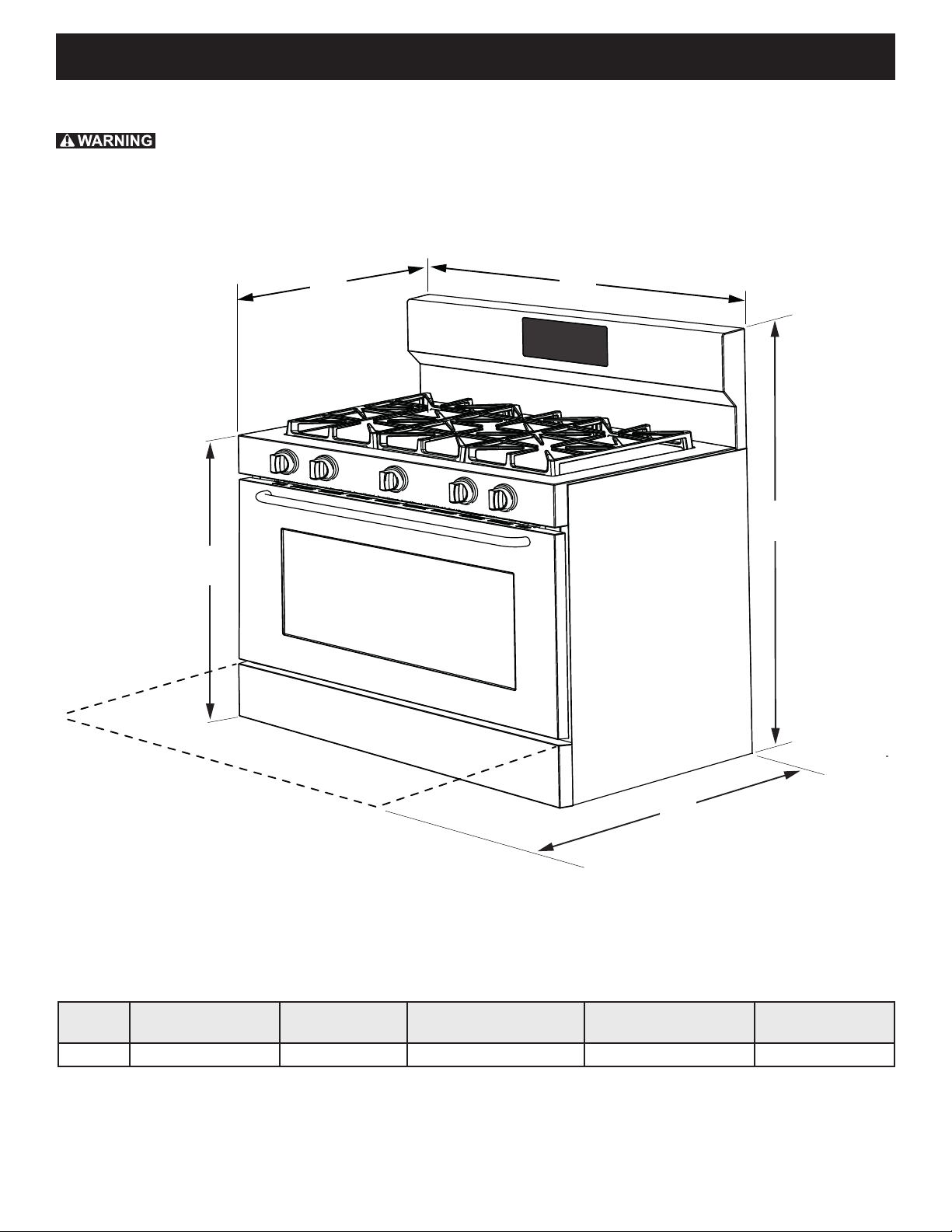
Do not install the unit in the cabinet before reading next two pages.
D
C
B
A
E
Figure 1: Product Dimensions
MODEL A. HEIGHT B. WIDTH
40" 49" (124.5cm) Max. 40" (101.6cm) 28 1/2" (72.4cm) Max. 36" (91.4cm) Max. 47 3/4" (121.3 cm)
C. DEPTH TO FRONT
OF RANGE
5
D. HEIGHT OF
COOKTOP
E. DEPTH WITH
DOOR OPEN
Page 6
40" DUAL FUEL RANGE INSTALLATION INSTRUCTIONS
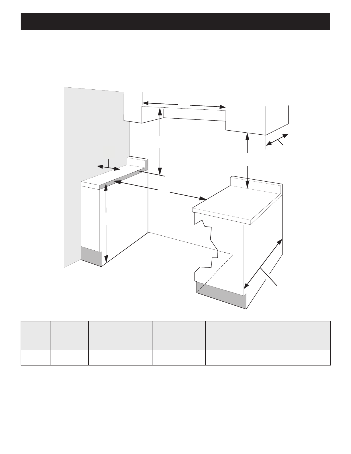
Cabinet Dimensions
Clearances and Dimensions
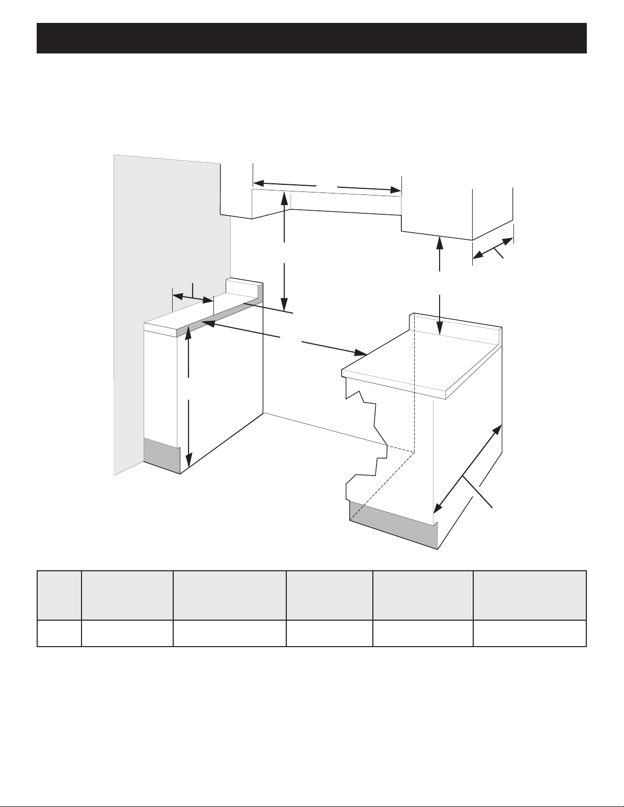
• Provide adequate clearances between the appliance and adjacent combustible surfaces.
• Location - Check location where the appliance will be installed. Check for proper electrical supply and oor
stability.
• Dimensions shown must be used. Given dimensions provide minimum clearance. Contact surface must be
solid and level.
J
H
G
I
F
Figure 2: Cabinet Dimensions
13" Max.
(33 cm Max.)
18" Min.
(45.7 cm Min.)
24" Min.
(61 cm Min.)
24½" max.
(62.2 cm Max.)
MODEL
40" 40 1/4" (102.2cm)
NOTES:
1. Do not seal the range to the side cabinets.
2. Clearance from adjacent walls or other vertical surfaces or structures such as cabinets.
3. Measurements listed are minimum clearance between the cooktop and the bottom of the cabinet.
4. 0" clearance between range and cabinets or vertical surfaces that are below the cooktop height.
5. 0" clearance between range back and rear wall or cabinet.
F. MINIMUM
CUTOUT WIDTH
G. HEIGHT OF
COUNTERTOP
36" (91.4cm) Standard
35 3/4" (90.8cm) Min.
H. CLEARANCE
FROM SIDE
WALLS
5" (12.7cm) Min. 30" (76.2cm) Min. 40" (101.6cm) Min.
6
2
I. CLEARNACE
FROM COOKTOP
AND CABINET
BOTTOM
J. CLEARANCE
WIDTH OF
3
OVERHEAD
CABINETS
Page 7
40" DUAL FUEL RANGE INSTALLATION INSTRUCTIONS
Follow instructions for
the type of installation you have
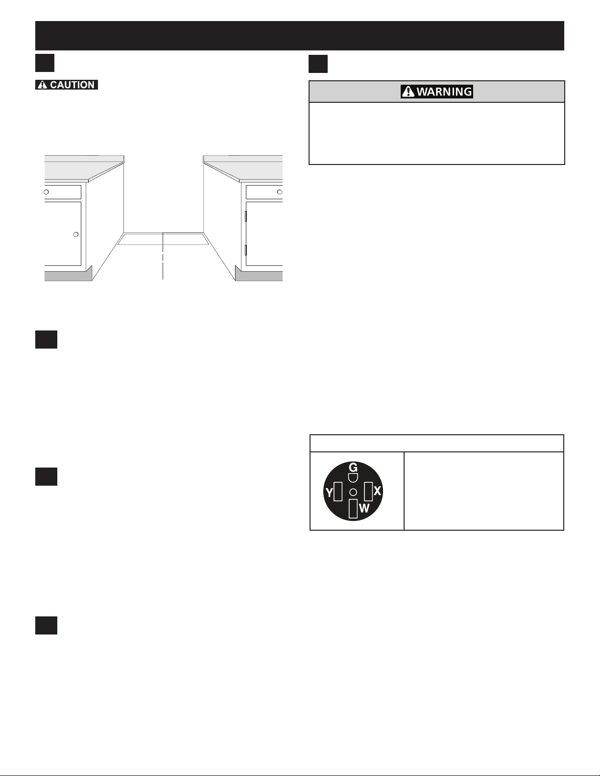
Center
Line of
Range
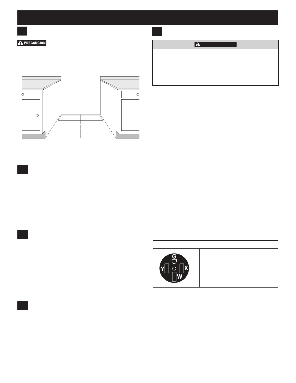
1
Cabinet Construction
To eliminate the risk of burns or re by
reaching over heated surface units, do not have cabinet
storage space above the range. If there is cabinet storage
space above range, reduce risk by installing a range
hood that projects horizontally a minimum of 5" (12.7 cm)
beyond the bottom of the cabinet.
Figure 3: Cabinet construction
1.1
Installation: Cabinet on Both Sides
1. If range will be installed with a cabinet on both sides,
Draw a center line on the oor between the cabinets
(Figure 5).
2. If back of range will not be ush with the wall (the
location of the outlet may not allow the range to be
positioned against the wall), draw a line on the oor
where the back edge of the range will be.
3. Install anti-tip brackets (see "Anti-Tip Bracket
Installation").
2
Electrical Requirements
Electrical Shock Hazard –Electrical ground is
required on this appliance. Use only the power cord
supplied with the appliance. Improper connections and
grounding may result in electric shock, damage to the
appliance, personal injury, re or death.
Grounding Requirements
This appliance must be installed and grounded by a
qualied technician.
In the United States, install in accordance with the National
Fuel Gas Code ANSI Z223.1/NPFA No. 54, latest edition
and National Electrical Code NFPA No. 70 latest edition,
and local electrical code requirements. In Canada, install in
accordance with CAN/CGA B149.1 and CAN/CGA B149.2
and CSA Standard C22.1, Canadian Electrical code, Part
1-latest editions and local electrical code requirements.
For personal safety, this appliance must be properly
grounded. For maximum safety, the power cord must
be plugged into an electrical outlet that is the correct
voltage, is correctly polarized and properly grounded
in accordance with local codes. It is the personal
responsibility of the consumer to have the appropriate
outlet with the correct, properly grounded wall receptacle
installed by a qualied electrician.
This appliance is intended to be plugged into a 14-50R
standard wall receptacle.
Electrical Wall Receptacle
1.2
Installation: Cabinet on One Side Only
1. If range will be installed with a cabinet on one side
only, move the range into nal position.
2. Draw a line on the oor along the side of the range
that is not against the cabinet. If back of range will
not be ush with the wall (the location of the outlet
may not allow the range to be positioned against the
wall), draw a line on the oor where the back edge of
the range will be.
3. Install anti-tip brackets (see "Anti-Tip Bracket
Installation").
1.3
Installation: Without Cabinet
1. If range will not be installed against a cabinet, move
range into nal position.
2. Mark on the oor along both sides of the range.
If back of range will not be ush with the wall (the
location of the outlet may not allow the range to be
positioned against the wall), draw a line on the oor
where the back edge of the range will be.
3. Install anti-tip brackets (see "Anti-Tip Bracket
Installation").
Required for all installations
4-Wire receptacle (14-50R)
When only 4-wire, single phase, 240 volt, 60 Hz, AConly electrical supply is available, this appliance requires
minimum 40 amp circuit protection fused on both sides of
the line.
A time-delay circuit breaker or fuse is recommended.
Be sure the wall receptacle is within reach of the
appliance's nal installed location.
Do not pinch the power supply cord between the range
and the wall.
7
Page 8
40" DUAL FUEL RANGE INSTALLATION INSTRUCTIONS
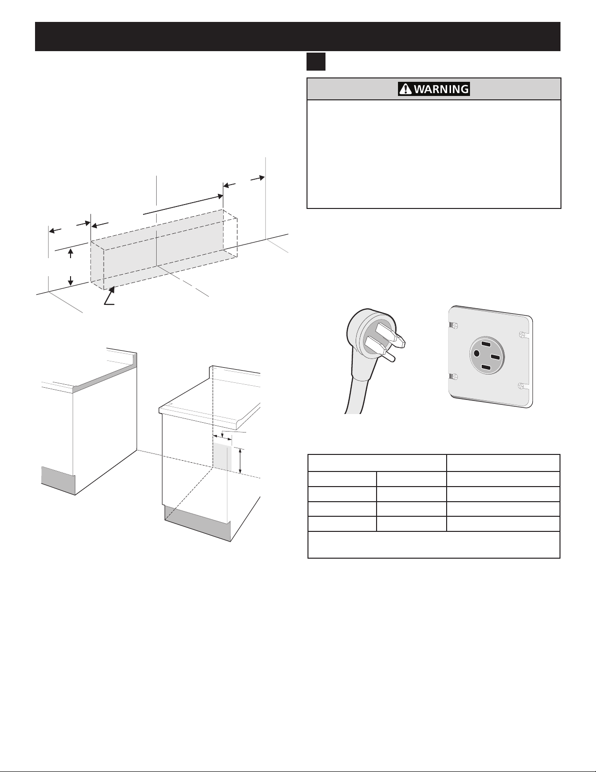
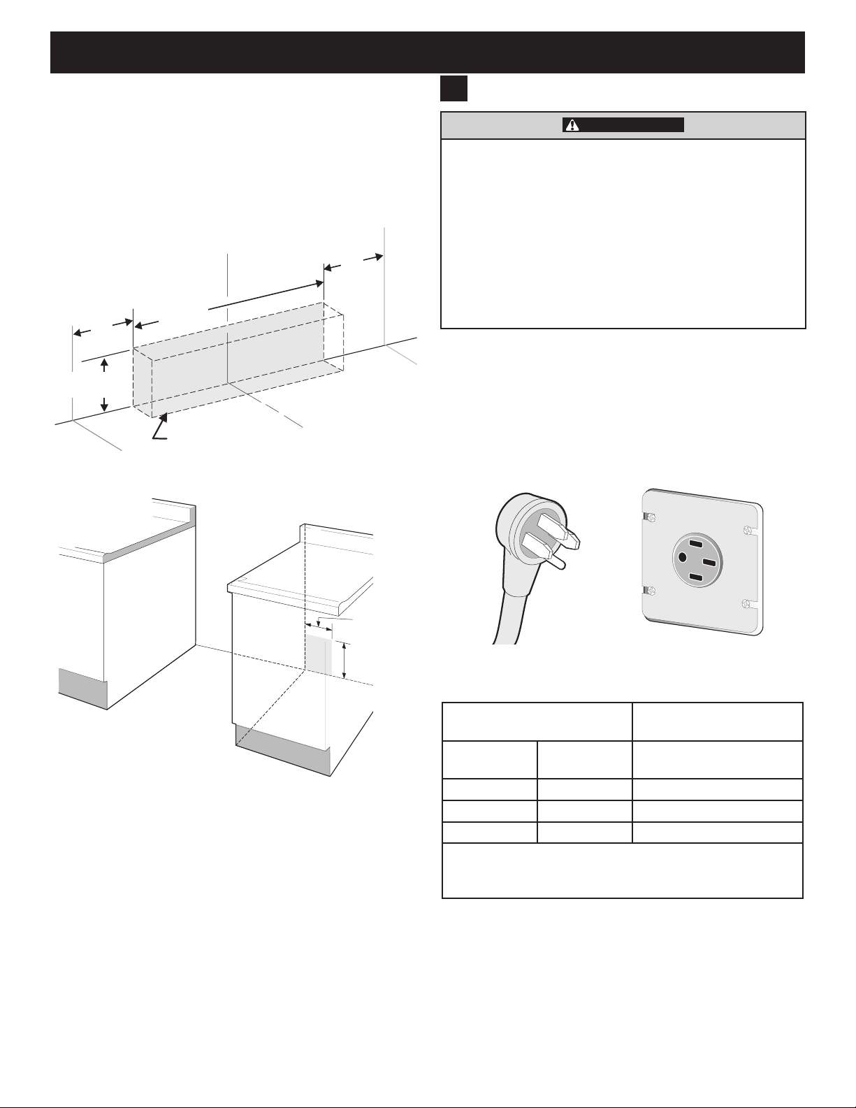
12”
(30.5 cm)
8”
(20.3 cm)
Locate Electrical Hook-up
Inside Shaded Area
Center
Line of
Range
10"
(25.4 cm)
10"
(25.4 cm)
7" Max.
(17.8 cm Max.)
20"
(50.8 cm)
FLOOR
WALL
Center
Line of
Range
Recommended Wall Outlet Installation
Locations
Suggested location of the wall outlet is shown in
Figure 4. The outlet may also be located in the lower
left corner of the adjacent right cabinet, as shown in
Figure 5.
Power Supply Cord
3
Electrical Shock Hazard –Do not attempt to install
the appliance directly to a junction box, modify the
factory-installed cord, or connect a different power
cord to the appliance. If the wall outlet is not sufcient
to support the requirements of this appliance, it is the
responsibility of the consumer to have the appropriate
outlet installed by an electrician. Improper installation
and electrical connections can result in electric shock,
damage to the appliance, personal injury, re, or death.
This appliance is equipped with a factory-connected,
4-wire power supply cord (Figure 6). This cord is rated
at 240 volts, 40 amps, and temperature rated at 194°F
(90°C). This cord is UL/CSA listed and has been tested
and approved for use with this appliance.
Figure 4: Outlet location behind range
Figure 5: Adjacent cabinet outlet location
Figure 6: Factory connected power supply cord
Appliance Rating* Power Supply Rating
120/240 Volts 120/208 Volts Amps
0-10 kW 0-7.6 kW 30
8.8-16.5 kW 7.8-12.5 kW 40 or 50
16.6-22.5 kW 12.6-18.5 kW 50
* The NEC calculated load is less than the total connec-
ted load listed on the serial plate.
8
Page 9
40" DUAL FUEL RANGE INSTALLATION INSTRUCTIONS
Shutoff Valve -
Open position
to appliance
to gas supply line
12”
(30.5 cm)
8“
(20.3 cm)
Fuel Supply Requirements
4
This unit is designed to operate on 4"(10.16 cm) water
column (1.0 kPa) natural gas manifold pressure.
A convertible pressure regulator is connected to the
range manifold and MUST be connected in series with
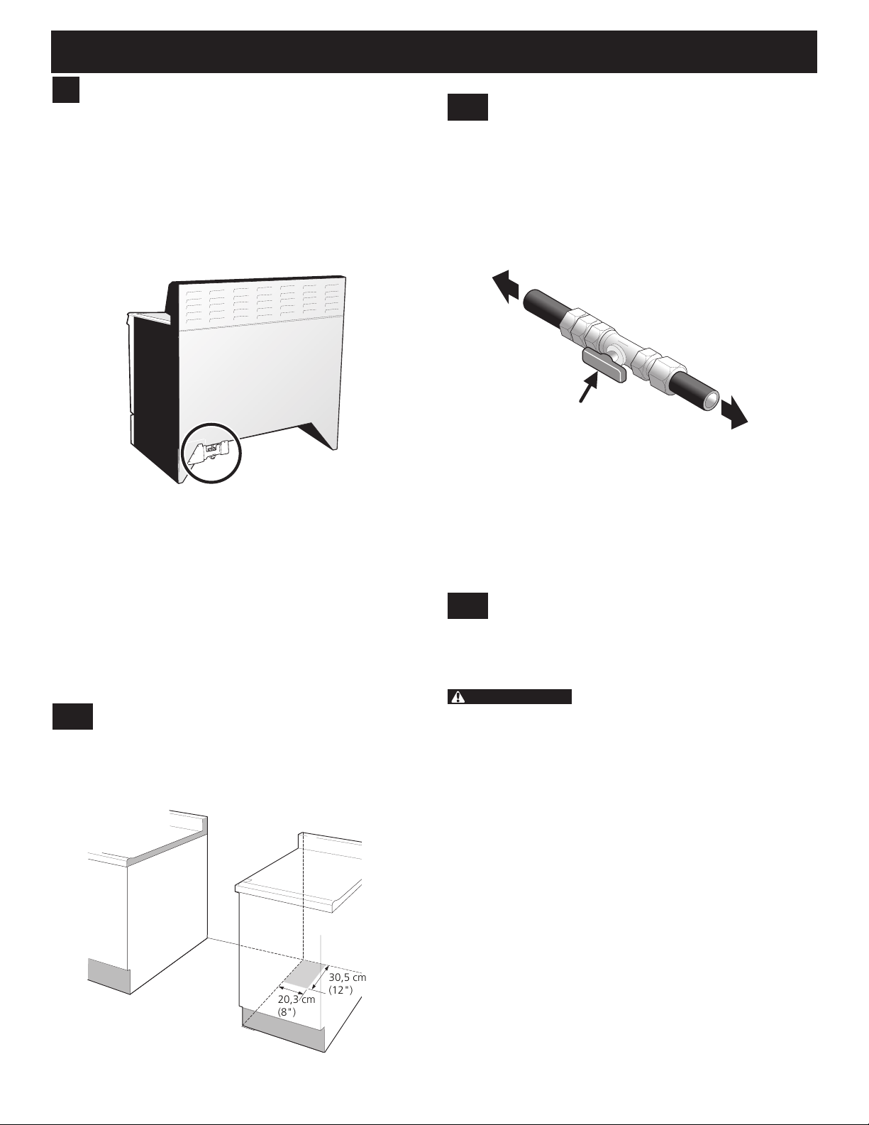
the gas supply line. The regulator is located as shown on
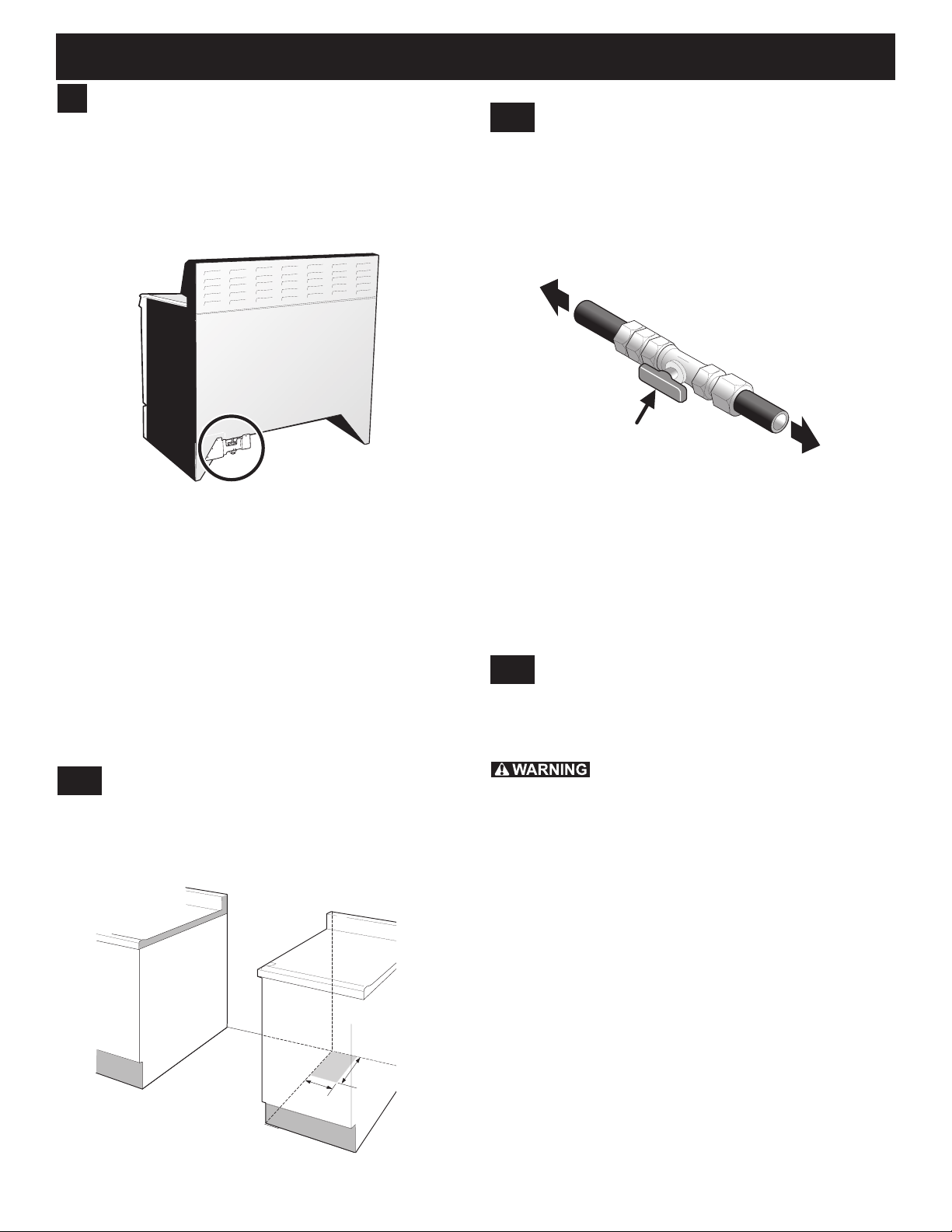
Figure 7 and it is accessible from front of the range.
4.2
Shutoff Valve
The supply line should be equipped with an approved
shutoff valve as shown in Figure 9. This valve should be
located in the same room as the range and should be in
a location that allows ease of opening and closing. Do
not block access to the shutoff valve. The valve is for
turning on or shutting off gas to the appliance.
For proper operation, the maximum inlet pressure to
the regulator should be no more than 14" (35.56 cm) of
water column pressure (3.5 kPa).
The inlet pressure to the regulator must be at least
1" (0.25 kPa) greater than the regulator manifold
pressure setting. The regulator is set for 4" (10.16 cm)
water column (1.0 kPa) Natural gas manifold pressure;
the inlet pressure must be at least 5" (12.60 cm) water
column (1.25 kPa) Natural gas.
For operation at 2000 ft. above sea level, appliance rating
is reduced by 4 percent for each additional 1000 ft.
4.1
The gas supply piping can be through the side wall of the
right cabinet. The right side cabinet is an ideal location
for the main shutoff valve, if the range is installed within
cabinet storage space.
Figure 7: Regulator location
Gas Supply Location
Figure 9: Shutoff valve
The gas supply between the shutoff valve and the
regulator may be connected by rigid piping or by A.G.A./
C.G.A.- approved exible metallic union-connected
piping where local codes permit use.
The user must know the location of the main shutoff
valve and have easy access to it.
4.3
Conversion to Liqueed Petroleum
(L.P.) Gas
This appliance allows for conversion to Liqueed
Petroleum (L.P.) Gas.
Personal injury or death from electrical
shock may occur if the conversion to L.P. gas is not
made by a qualied installer or electrician. Any additions,
changes or conversions required in order for this
appliance to satisfactorily meet the application needs
must be made by a qualied technician.
If L.P. conversion is needed, contact your local L.P.
Gas provider for assistance. The L.P. conversion kit is
provided with this appliance and is located on the lower
REAR (back side) panel of the range. Before installing
the kit be sure to read the L.P. Installation Instructions
and follow them carefully when making the installation.
For LP/Propane gas, the regulator must be set for
10"(25.4 cm) water column (2.5 kPa) manifold pressure;
the inlet pressure must be at least 11"(27.9 cm) water
column (2.75 kPa).
Figure 8: Recommended gas supply location
9
Page 10
40" DUAL FUEL RANGE INSTALLATION INSTRUCTIONS
Flare
Union
Flare
Union
GAS FLOW
Manual
Shutoff
Valve
Pressure
Regulator
On
Off
Flexible
Connector
Access
Cap
Nipple Nipple
Connect Fuel Supply
5
5.1
Fuel Supply Connection
This appliance must be installed,
grounded, and serviced by a qualied installer or service
technician.
Do not make connections too tight. The
regulator is die cast. Overtightening may crack the
regulator resulting in a gas leak and possible re or
explosion.
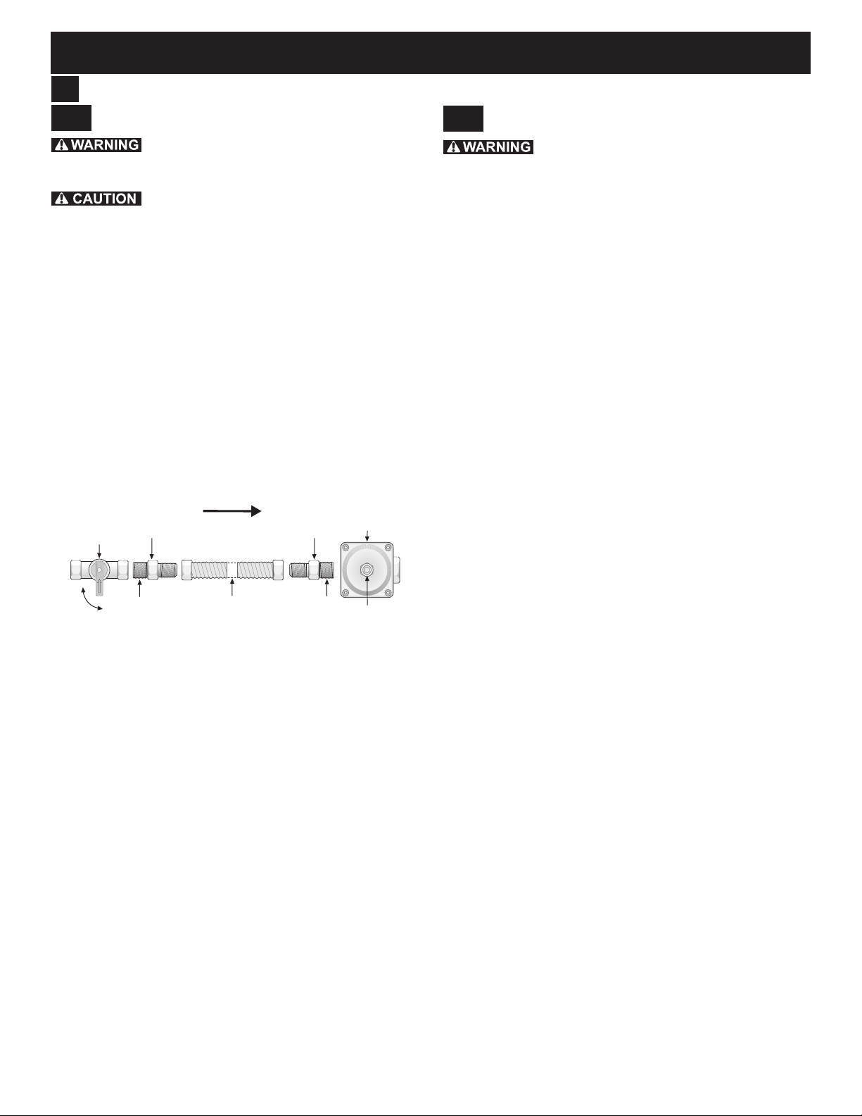
This appliance includes a regulator. The gas supply line
requires the following parts which are not supplied with
the appliance:
• Manual shutoff valve
• 1/2" nipples (2)
• 1/2" are union adapter (2)
• Flexible connector
The gas supply line to the shutoff valve should be
1/2"(1.27 cm) or 3/4"(1.9 cm) solid pipe.
Install the gas supply pipe to the pressure regulator in
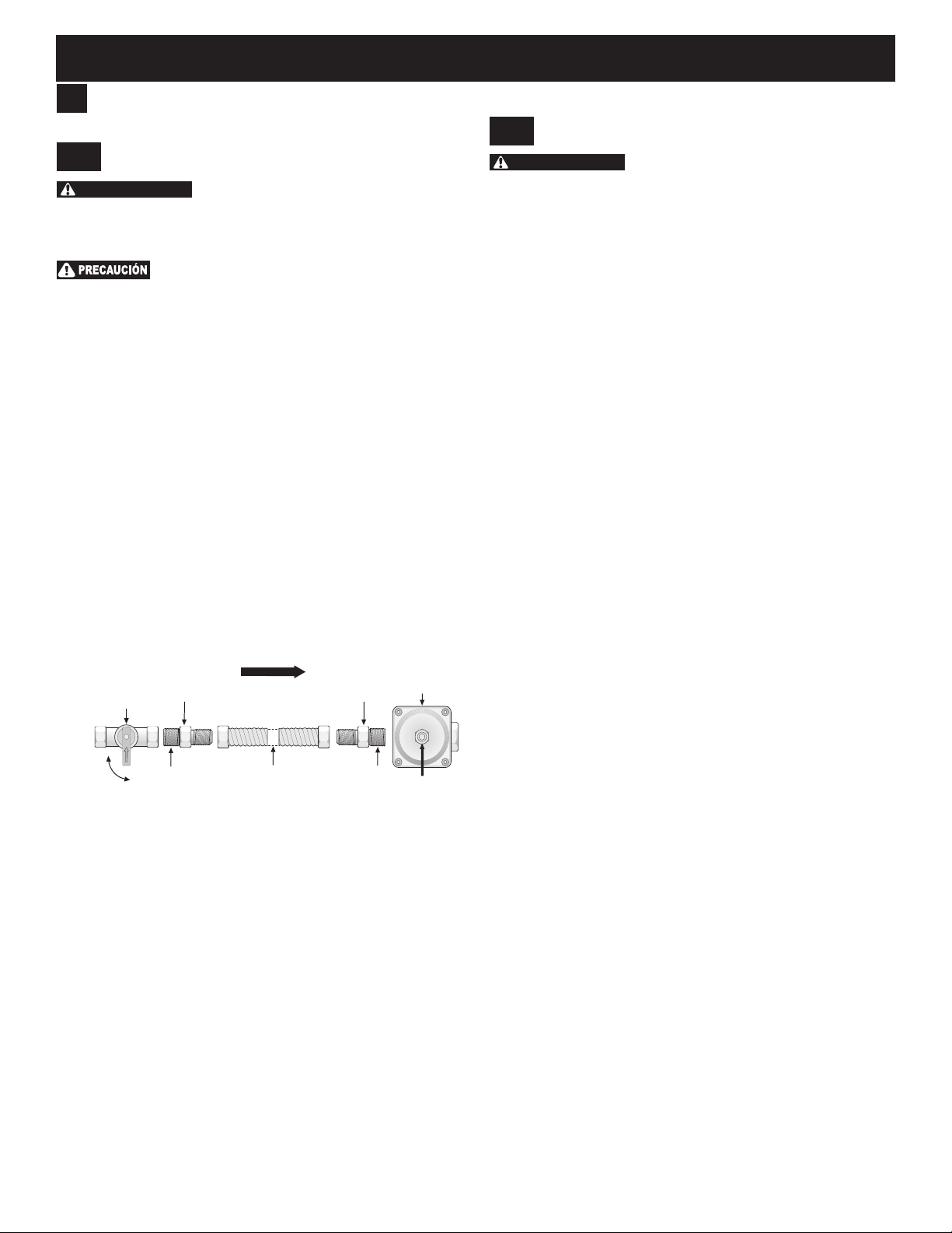
the order shown in Figure 10. All connections should be
tightened with a wrench.
5.2
Check For Leaks
Do not use a ame to check for leaks from
gas connections. Checking for leaks with a ame may
result in a re or explosion.
After connecting the range to the gas supply, check the
system for leaks with a manometer. If a manometer is not
available, turn on the gas supply and use a liquid leak
detector (or soap and water) at all joints and connections
to check for leaks. Leaks will be indicated by bubbles
appearing at the connections or joints.
All openings in the wall or oor where the range is to be
installed must be sealed.
1. Tighten all connections if necessary to prevent gas
leakage in the cooktop or supply line.
2. Disconnect this range and its individual shutoff valve
from the gas supply piping system during any pressure
testing of the system at test pressures greater than
1/2 psig (3.5 kPa or 14"(35.56 cm) water column).
3. Isolate the range from the gas supply piping system by
closing its individual manual shutoff valve during any
pressure testing of the gas supply piping system at
test pressures equal to or less than 1/2 psig (3.5 kPa
or 14"(35.56 cm) water column).
Figure 10: Fuel supply connection ow
When using exible gas conduit on the range, allow
sufcient slack to pull the range outside the cutout for
cleaning or servicing.
Use pipe-joint compound made for use with Natural and
LP/Propane gas to seal all gas connections. If exible
connectors are used, be certain connectors are not
kinked.
Do not allow the exible conduit to get pinched between
the wall and the range.
10
Page 11
40" DUAL FUEL RANGE INSTALLATION INSTRUCTIONS
Install the Oven Racks
6
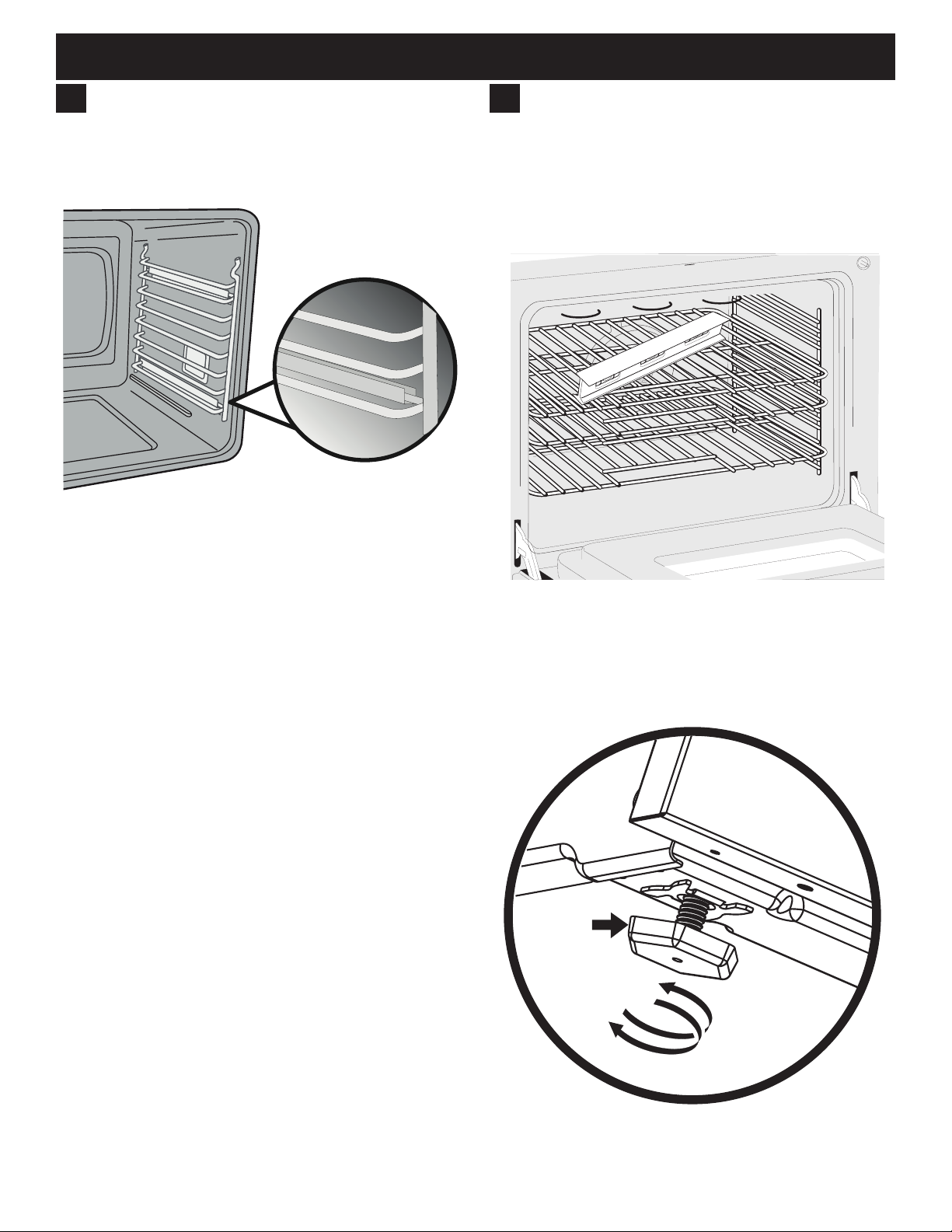
The oven racks are supported inside the oven cavity by
two ladder racks, installed on the oven walls.
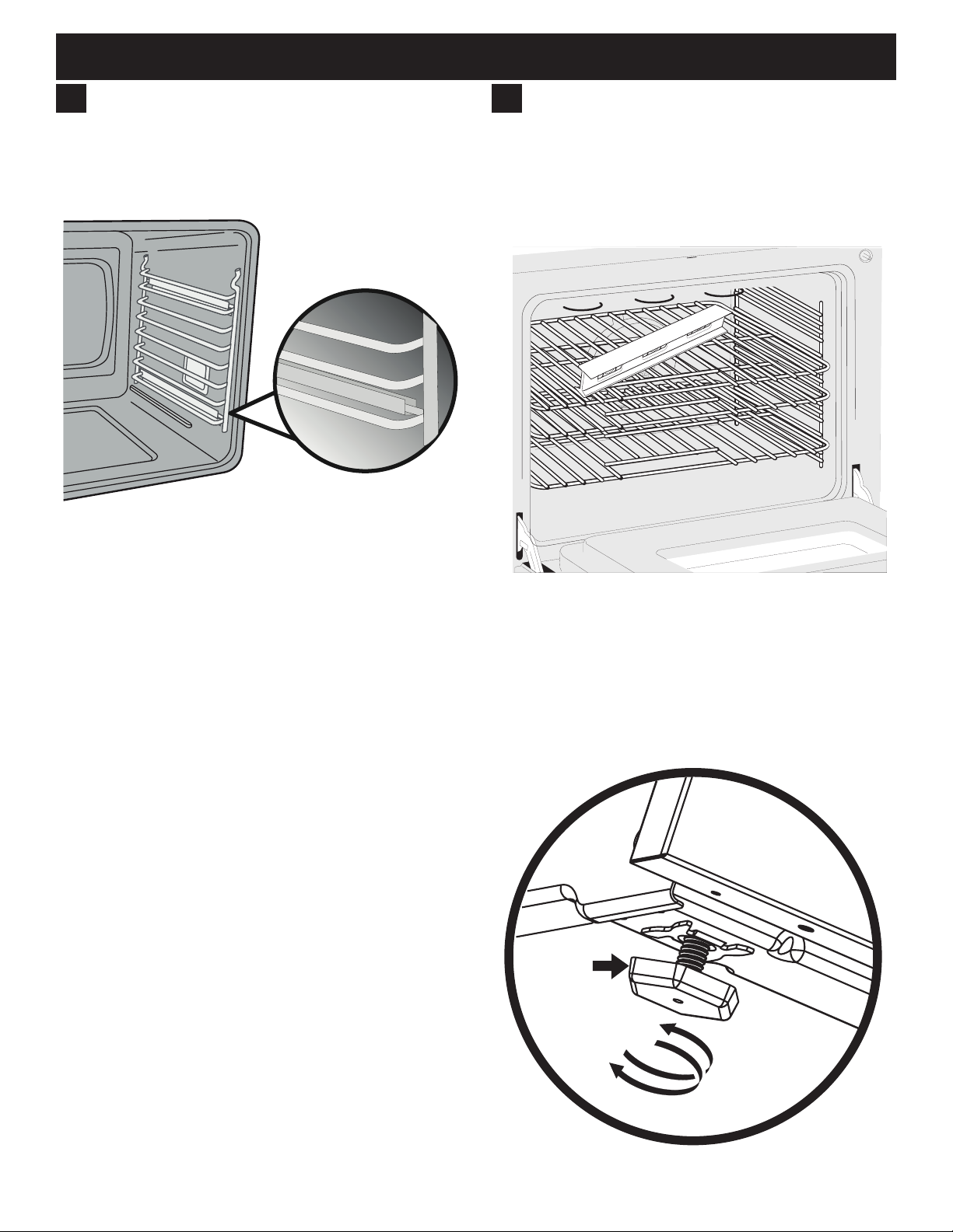
1. Place the ladder racks hook-side up into the support
brackets located on the oven sides (see Figure 11).
Figure 11: Ladder rack supports
2. Place the at oven racks into the desired positions.
To aid installation and movement of oven racks, apply
a thin layer of cooking oil to the sides of the oven racks
that contact the ladder supports.
7
Level the Range
Level the range and set cooktop height before
installation in the cut-out opening (if applicable).
1. Install an oven rack in the center of the oven.
2. Place a level on the rack (Figure 12). Take two
readings with the level placed diagonally in one
direction and then the other.
Figure 12: Use the oven racks to level appliance
3. Level the range, if necessary, by adjusting the four
leg levelers with a wrench (Figure 13).
4. Slide range into cut-out opening and double check
for levelness. If the range is not level, pull unit out
and readjust leveling legs, or make sure oor is level.
Leg
Leveler
Raise
Lower
11
Figure 13: Adjusting appliance height
Page 12
40" DUAL FUEL RANGE INSTALLATION INSTRUCTIONS
8
Install Anti-Tip Bracket
To reduce the risk of tipping the appliance,
the appliance must be secured to the oor by the properly
installed anti-tip bracket and screws packed with the
range. These parts are located in the oven. Failure to
install the anti-tip bracket will allow the range to tip over if
excessive weight is placed on an open door or if a child
climbs on it. Serious injury might result from spilled hot
liquids or from the range itself.
If range is ever moved to a different location, the antitip brackets must also be moved and installed with the
range.
Tools Required:
• Adjustable Wrench
• Ratchet
• Drill & 1/8" (0.32 cm) bit
• 5/16" (0.8 cm) Nut driver
• Level
Tip Over Hazard
• A child or adult can tip the range
and be killed.
• Verify the anti-tip device has been
installed to floor or wall.
• Ensure the anti-tip device is re-engaged to floor or wall
when the range is moved.
• Do not operate the range without the anti-tip device in
place and engaged.
• Failure to follow these instructions can result in death or
serious burns to children and adults.
Range
leveling leg
Anti-tip
bracket
8.1
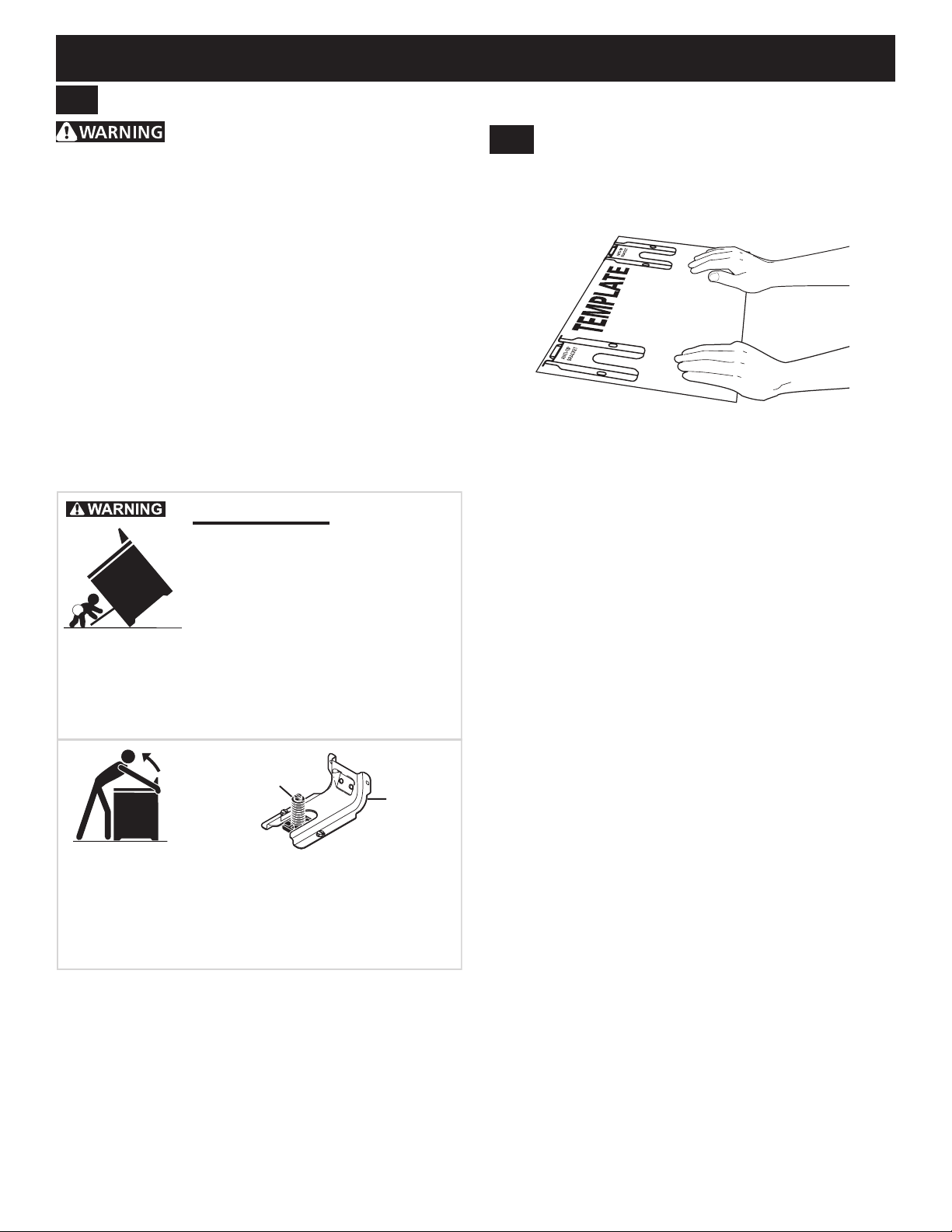
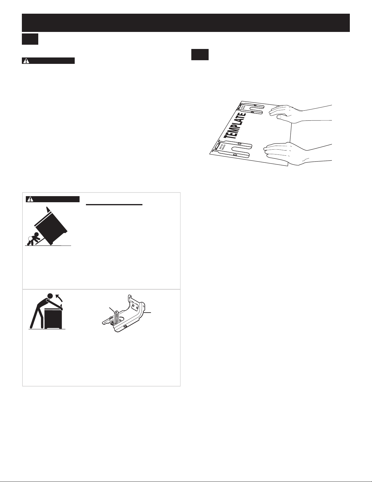
Locate the Bracket Using the Template
Bracket may be located on either the left or right side of
the range. Mark the oor or wall where left or right side of
the range will be located.
Figure 14: Bracket template
If rear of range is against the wall or no further than 1 1/4”
(3.2 cm) from wall when installed, you may use the wall
or oor mount method. If moulding is installed and does
not allow the bracket to t ush against the wall, remove
moulding or mount bracket to the oor.
For wall mount, locate the bracket by placing the back
edge of the template against the rear wall and the side
edge of template on the mark made referencing the side
of the range. Place bracket on top of template and mark
location of the screw holes in wall.
If rear of range is further than 1 1/4” (3.2 cm) from the wall
when installed, attach bracket to the oor. For oor mount,
locate the bracket by placing back edge of the template
where the rear of the range will be located.
Mark the location of the screw holes shown in template.
To check if the anti-tip bracket is installed properly, use both
arms to grasp the rear edge of the range back. Carefully
attempt to tilt range forward. When properly installed, the range
should not tilt forward.
Refer to the anti-tip bracket installation instructions supplied
with your range for proper installation.
12
Page 13
40" DUAL FUEL RANGE INSTALLATION INSTRUCTIONS
Leveling Leg
Anti-Tip Bracket
Floor Mount
8.2
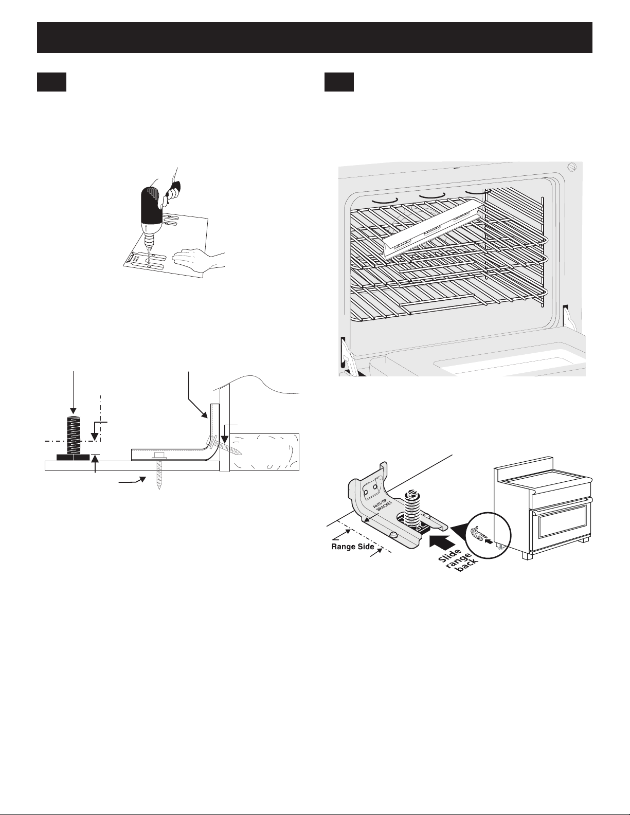
Drill Pilot Holes and Fasten Bracket
Drill a 1/8” pilot hole where screws are to be located.
If bracket is to be mounted to the wall, drill pilot hole at
an approximate 20° downward angle. If bracket is to
be mounted to masonry or ceramic oors, drill a 3/16”
(4.8 mm) pilot hole 1-3/4” deep.
Figure 15: Drill pilot holes
The screws provided may be used in wood or concrete
material. Use a 5/16” nut-driver or at head screwdriver to
secure the bracket in place.
8.3
Check Level and Position the Range
Check the level of the nal installation. Note: A minimum
clearance of 1/8” is required between the bottom of the
range and the levelling leg to allow room for the bracket.
Use a spirit level to check your adjustments.
1/8" Minimum
Figure 16: Fastening the bracket
Wall Mount
Figure 17: Use the oven racks to level appliance
Slide range into position.
Wall Plate
Figure 18: Slide appliance into bracket
To check if the anti-tip bracket is installed properly,
use both arms and grasp the rear edge of range back.
Carefully attempt to tilt range forward. When properly
installed, the range should not tilt forward.
If range is moved to a different location, the anti-tip
brackets must also be moved and installed with the range.
13
Page 14
40" DUAL FUEL RANGE INSTALLATION INSTRUCTIONS
9
Prepare Burner Assemblies
9.1
Install Burner Caps
To prevent are-ups use the cooktop with
all burner caps properly installed.
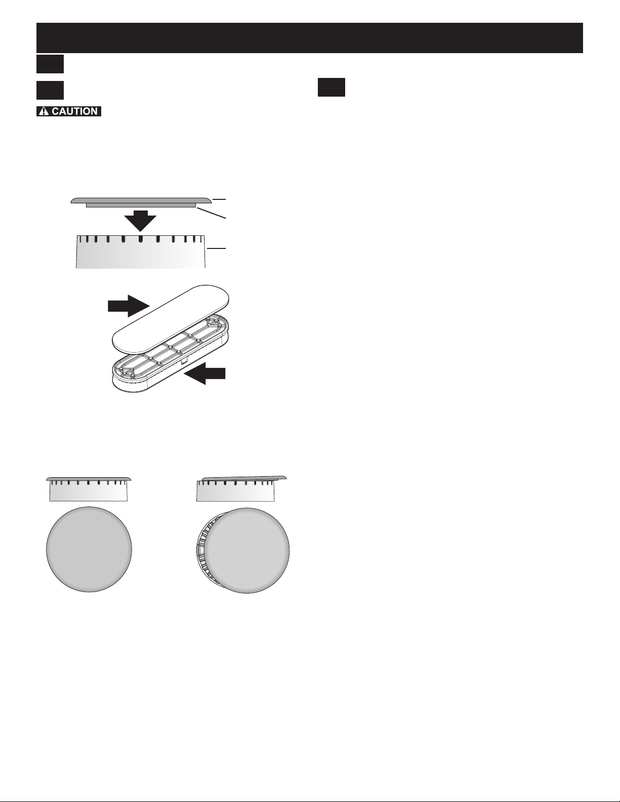
1. Place a burner cap on each burner head, matching
the cap size to the head size (see Figure 19). The
cap for each burner has an inner locating ring which
centers the cap correctly on the burner head.
Burner cap
Locating ring
Burner head
Burner cap
Burner head
9.2
Check Ignition on Surface
Burners
Operation of electric igniters should be checked after
range and supply line connectors have been carefully
checked for leaks and range has been connected to
electric power. To check for proper lighting:
1. Push in and turn a surface burner knob to the
sparking position. All electronic surface ignitors will
spark at the same time. Only the burner you are
turning on will ignite.
2. The surface burner should light once the ow of gas
reached the surface burner. Each burner should light
within four seconds in normal operation after air has
been purged from supply lines. Visually check that
burner has lit.
3. Once the burner lights, the control knob should be
turned out of the LITE position.
Turn on each of the surface burners and check to see
that they light properly and that the ames are even.
Adjust settings if necessary.
Figure 19: Burner cap assembly
2. Make sure each burner cap is properly aligned and
level, as shown in Figure 20. Burners may not light or
burn evenly if the burner caps are not correctly place
on the head.
Correct cap placement Incorrect cap placement
Figure 20: Burner cap placement
14
Page 15
40" DUAL FUEL RANGE INSTALLATION INSTRUCTIONS
9.3
Adjust Low Settings on Surface
Burners
To adjust the low setting of surface burners:
1. Push in and turn control to LITE until burner ignites.
2. Quickly turn knob to LOWEST POSITION.
3. If burner goes out, reset control to OFF.
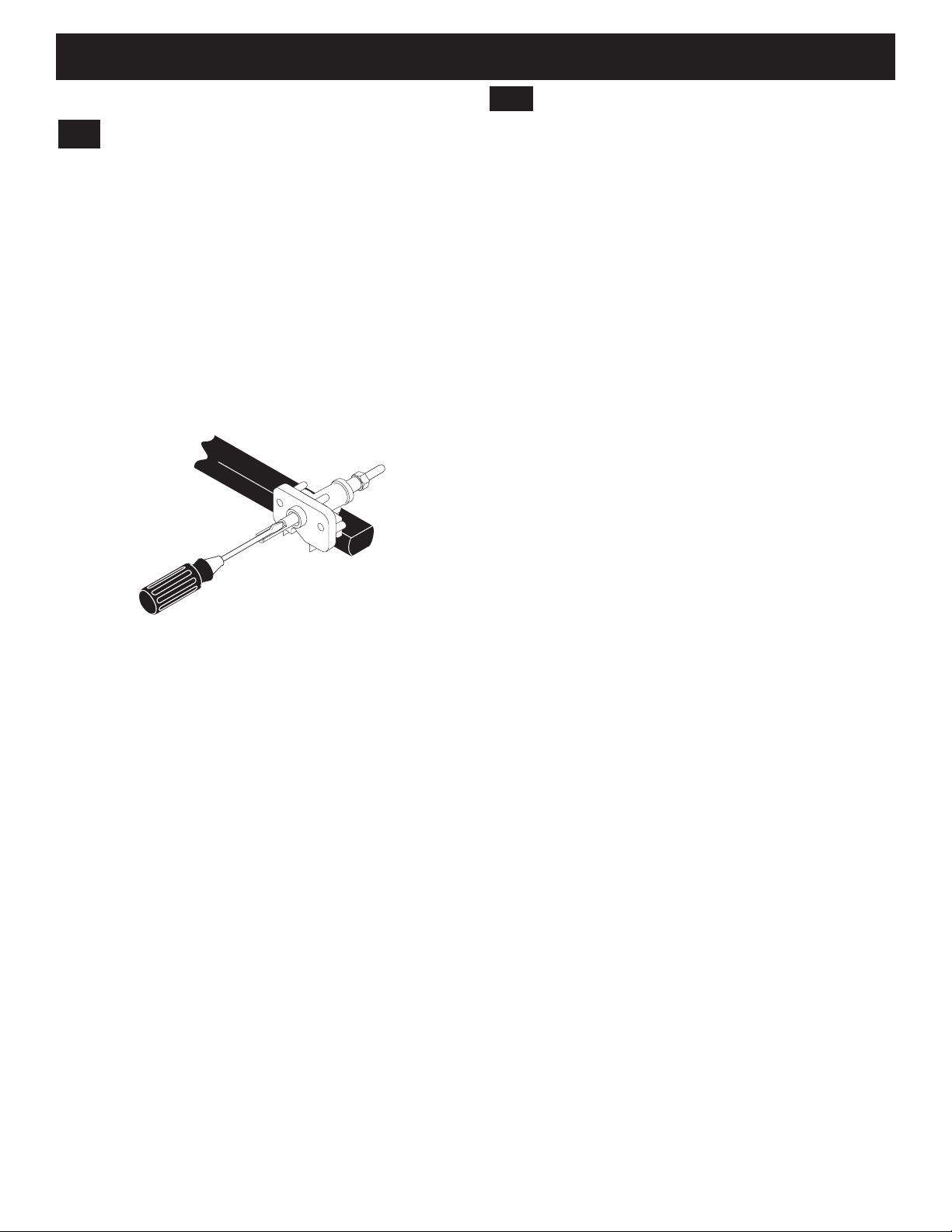
4. Remove the surface burner control knob and
decorative ring.
5. Insert a thin-bladed screwdriver into the hollow valve
stem and engage the slotted screw inside as shown in
Figure 21. Flame size can be increased or decreased
by turning the screw.
Figure 21: Turn to adjust surface ame
Check Oven Operation
10
Refer to the Use and Care Guide packaged with the
range for operating instructions and for care and
cleaning of your range.
Remove all packaging from the oven before testing.
The oven is equipped with an electronic oven control.
Each of the functions has been factory checked before
shipping. However, it is suggested that you verify the
operation of the electronic oven controls once more.
Refer to the Owner's Guide for operation. Follow the
instructions for the Clock, Timer, Bake, Broil, Convection,
and Clean functions.
Bake–After setting the oven to 350°F (177°C) for baking,
the oor of the oven cavity should become warm.
Broil–When the oven is set to BROIL, the upper element
in the oven should become red.
Clean–When the oven is set for a self-cleaning cycle,
the upper element should become red during the preheat
portion of the cycle. After reaching the self-cleaning
temperature, the oor of the oven cavity should become
hot.
Convection–When the oven is set to CONV. BAKE/
ROAST at 350°F (177°C), both elements cycle on and
off alternately and the convection fan will turn. The
convection fan will stop turning when the oven door is
opened during convection baking or roasting.
6. Adjust ame until you can quickly turn knob from the
sparking position to the lowest ame position without
extinguishing the ame. Flame should be as small as
possible without going out.
Notes:
• Air mixture adjustment is not required on surface
burners.
• Some models have two ames on a burner. The center
ame on these burners is not adjustable.
15
Page 16
40" DUAL FUEL RANGE INSTALLATION INSTRUCTIONS
After Installation
11
When All Hookups are Complete
Make sure all controls are left in the OFF position.
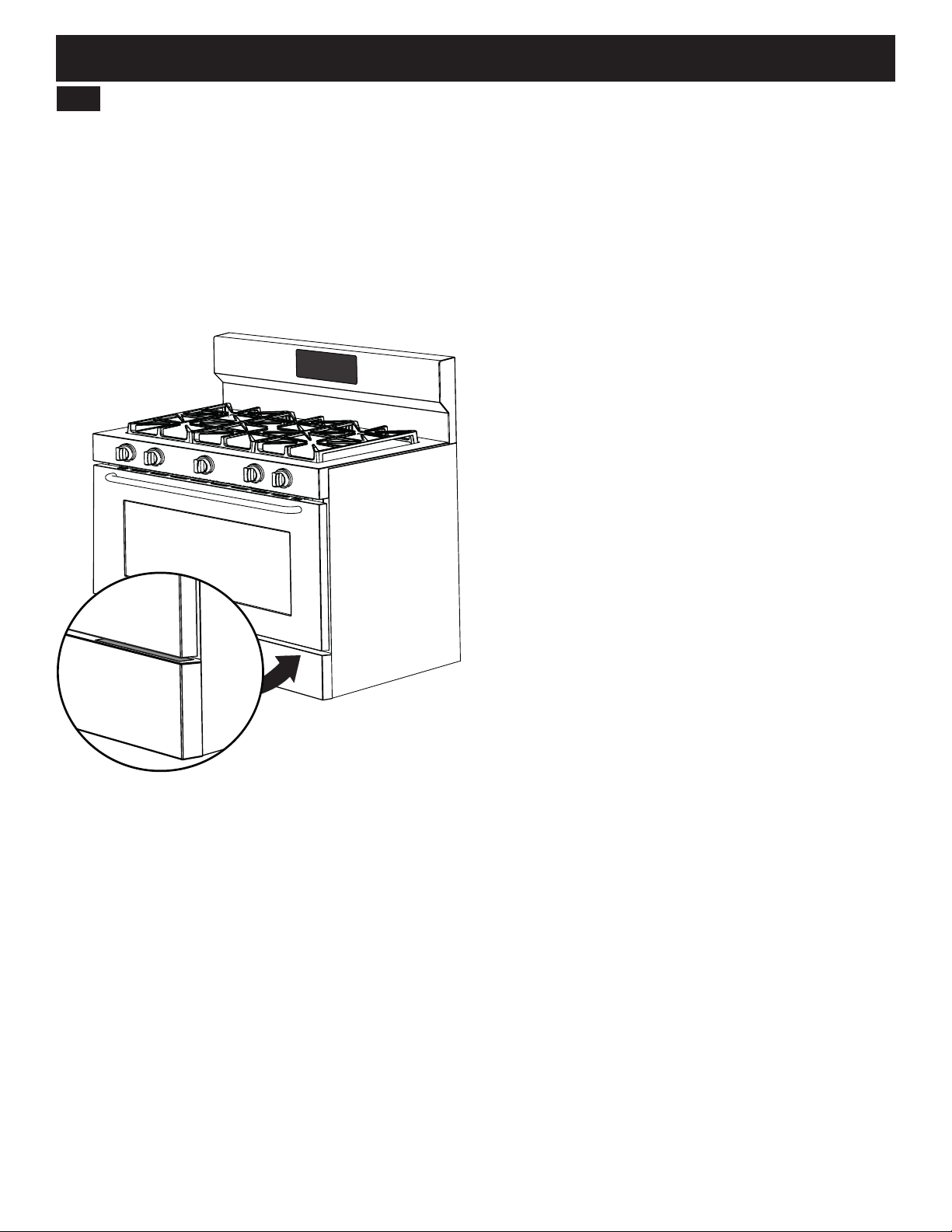
Model and Serial Number Location
The serial plate is located on top of the range's lower
front panel, and can be clearly viewed when the door is
open. When ordering parts for or making inquiries about
your range, have the model and serial numbers ready.
(Figure 22).
Figure 22: Model, serial number location
Before You Call for Service
Read the Avoid Service Checklist and operating
instructions in your Owner's Guide. It may save you time
and expense. The list includes common occurrences that
are not the result of defective workmanship or materials
in this appliance.
Refer to the warranty and service information in your
Owner's Guide for our phone number and address.
Please call or write if you have inquiries about your
range product and/or need to order parts.
16
Page 17
INSTRUCCIONES DE INSTALACIÓN DE LA COCINA DE DOBLE COMBUSTIBLE DE 40"
ADVERTENCIA
INSTRUCCIONES DE INSTALACIÓN
COCINA DE DOBLE COMBUSTIBLE DE 40"
LAS OPERACIONES DE INSTALACIÓN Y SERVICIO TÉCNICO DEBE REALIZARLAS
UN INSTALADOR CUALIFICADO.
IMPORTANTE: GUARDAR PARA USO DEL INSPECTOR ELÉCTRICO LOCAL.
LEA Y GUARDE ESTAS INSTRUCCIONES PARA FUTURA CONSULTA.
Estados Unidos
POR SU SEGURIDAD: No almacene ni
utilice gasolina ni otros vapores o líquidos inamables
cerca de este o algún otro electrodoméstico.
Índice
Instrucciones importantes para la seguridad ...........18-20
Dimensiones del producto ............................................ 21
Dimensiones del armario .............................................. 22
Construcción del armario.............................................. 23
Requisitos eléctricos................................................23-24
Cable de alimentación eléctrica.................................... 24
Requisitos de suministro de combustible ..................... 25
Conexión del suministro de combustible ...................... 26
Canadá
Instalación de las parrillas del horno ............................ 27
Nivelación de la cocina ................................................. 27
Instalación del soporte antivuelco ...........................28-29
Preparación de los conjuntos de quemador ............ 30-31
Comprobación del funcionamiento del horno ............... 31
Después de la instalación............................................. 32
Ubicación de la placa que informa del
número de modelo y de serie ....................................... 32
Notas importantes para el instalador
1. Lea todas las indicaciones contenidas en estas
instrucciones antes de instalar la cocina.
2. Retire todo el material de embalaje de los
compartimentos del horno antes de conectar
el suminisro de energía eléctrica a la cocina.
3. Se debe instalar el soporte antivuelco facilitado con
el electrodoméstico.
4. Cumpla toda la normativa vigente.
5. Asegúrese de dejar estas instrucciones al consumidor.
Impreso en Estados Unidos
Nota importante para el consumidor
1. Guarde estas instrucciones con la guía del propietario
para futuras consultas.
2. Cuando se utilizan electrodomésticos que generan calor
es necesario tomar ciertas precauciones de seguridad.
Estas precauciones se explican en el manual de uso
y cuidado. Lea detenidamente el manual.
3. Asegúrese de que el electrodoméstico sea instalado
y conectado a tierra por un instalador o técnico de
servicio cualicado.
Nº pieza 809019101 (1611) Rev. A
English – páginas 1-16
Español – páginas 17-32
Français – páginas 33-48
17
Page 18
INSTRUCCIONES DE INSTALACIÓN DE LA COCINA DE DOBLE COMBUSTIBLE DE 40"
ADVERTENCIA
INSTRUCCIONES DE SEGURIDAD IMPORTANTES
Las operaciones de instalación, puesta a tierra y servicio técnico de este electrodoméstico debe
realizarlas un instalador o técnico de servicio cualicado.
Este manual contiene símbolos e instrucciones de seguridad importantes. Preste atención a estos símbolos y
siga todas las instrucciones. No intente instalar o usar su electrodoméstico hasta haber leído las precauciones de
seguridad indicadas en este manual. Las indicaciones de seguridad presentes en este manual están etiquetadas
como "ADVERTENCIA" o "PRECAUCIÓN" de acuerdo con el nivel de riesgo.
Las advertencias e instrucciones importantes que aparecen en esta guía no pretenden cubrir todas las posibles
condiciones y situaciones que pueden ocurrir. Se debe tener sentido común, precaución y cuidado durante la instalación,
mantenimiento y uso del electrodoméstico.
Este es el símbolo de las alertas de seguridad. Se usa para alertar sobre peligros potenciales de lesiones.
Obedezca todos los mensajes de seguridad que lleven este símbolo para evitar posibles lesiones o la muerte.
Representa una situación potencialmente peligrosa que, si no se evita, puede tener como
resultado la muerte o una lesión grave.
Representa una situación potencialmente peligrosa que, si no se evita, puede tener como resultado una
lesión leve o moderada.
IMPORTANTE: Indica información de instalación, operación, mantenimiento u otra información útil no relacionada con
situaciones de peligro.
ADVERTENCIA
• Cuando se desplace la cocina, asegúrese de que el
dispositivo antivuelco es instalado de nuevo en el suelo
o la pared.
• No utilice la cocina sin este dispositivo acoplado.
• El incumplimiento de estas instrucciones puede provocar
la muerte o quemaduras graves a niños y adultos.
Para comprobar si el soporte antivuelco se ha instalado
correctamente, sostenga con ambas manos el borde posterior
de la parte trasera de la cocina. Con cuidado, trate de
inclinarla hacia delante. Cuando se ha instalado
correctamente, la cocina no debería inclinarse.
Consulte las instrucciones de instalación del soporte antivuelco
de su cocina.
Peligro de volcado
• Un niño o adulto puede volcar
la cocina y resultar muerto.
• Verifique que el dispositivo
antivuelco ha sido instalado
en el suelo o la pared.
Pata
niveladora
de la cocina
Soporte
antivuelco
ADVERTENCIA
Si no se sigue exactamente
la información contenida en este manual
podría ocurrir un incendio o explosión
causando daños materiales, lesiones o muerte.
POR SU SEGURIDAD:
—No almacene ni utilice gasolina ni
otros vapores o líquidos inflamables
cerca de este o algún otro electrodoméstico.
—QUÉ HACER SI HUELE A GAS:
• No encienda ningún electrodoméstico.
• No toque ningún interruptor eléctrico;
no utilice ningún teléfono de la casa.
• Llame inmediatamente a la empresa
de suministro de gas desde el teléfono
de un vecino. Siga las instrucciones de
la empresa de suministro.
• Si no puede ponerse en contacto con
la empresa de suministro de gas, llame
a los bomberos.
—Las operaciones de instalación y servicio
técnico debe realizarlas un instalador
o proveedor de servicios cualificado
o la empresa suministradora de gas.
18
Page 19
INSTRUCCIONES DE INSTALACIÓN DE LA COCINA DE DOBLE COMBUSTIBLE DE 40"
ADVERTENCIA
• Destruya la caja de cartón y las bolsas de plástico
• Peligro de peso excesivo -- Para mover e
instalar la cocina se necesitan dos personas como
mínimo. Si no se cumple esta instrucción podrian
provocarse problemas de espalda y otras lesiones.
• Almacenamiento en o sobre el
electrodoméstico -- No se deben guardar
materiales inflamables en el horno o microondas,
cerca de quemadores o elementos de superficie,
ni en el cajón del horno o el cajón calentador
(si se dispone). Esto incluye objetos de
papel, plástico o tela, como libros de cocina,
utensilios de plástico o paños, así como
líquidos inflamables. No almacene materiales
explosivos, como aerosoles, en o cerca del
electrodoméstico.
• No deje a los niños solos -- No se debe dejar
a los niños solos o sin vigilancia en el área donde
se usa el electrodoméstico. Nunca permita que
los niños se sienten o pongan de pie sobre ninguna
parte del electrodoméstico, incluyendo el cajón
de almacenamiento, el cajón asador inferior,
el cajón calentador o el horno doble inferior.
• No guarde artículos que despierten el interés
de los niños en armarios situados encima del
electrodoméstico o en los protectores traseros
de cocinas. Si los niños se suben a la cocina para
alcanzar dichos artículos podrían sufrir lesiones
graves.
• Pisar, apoyarse o sentarse en la puerta o cajones
de este electrodoméstico puede tener como
resultado lesiones graves y también puede causar
daños al electrodoméstico.
• No utilice el horno ni el cajón calentador
(si se dispone) como armario.
• No utilice nunca el electrodoméstico como estufa
para calentar o caldear la habitación. Hacerlo podría
provocar intoxicación de monóxido de carbono
y sobrecalentamiento del electrodoméstico.
• No almacene ni utilice gasolina ni otros vapores
o líquidos inamables cerca de este o algún otro
electrodoméstico.
• No se deben utilizar aparatos de cortina de aire
o campanas de cocina que funcionen soplando un
ujo de aire descendente sobre una cocina o placa
de cocción a gas cuando el aparato o campana y la
cocina o placa de cocción no hayan sido diseñadas,
probadas y certicadas por un laboratorio de ensayo
independiente para su uso combinado.
INSTRUCCIONES IMPORTANTES DE DESEMBALAJE
E INSTALACIÓN
Lea y siga las instrucciones y precauciones siguientes
para desembalar, instalar y realizar el servicio técnico
de su electrodoméstico:
19
después de desembalar la cocina. No deje nunca
que los niños jueguen con el material de embalaje.
No quite la etiqueta de cableado ni otra información
adherida al electrodoméstico. No quite la placa del
número de modelo/serie.
• Las temperaturas frías pueden dañar el control
electrónico. Cuando se utilice este electrodoméstico
por primera vez, o cuando haya estado fuera de
uso durante un periodo prolongado de tiempo,
asegúrese de mantenerlo por encima de 0 ºC
(32 ºF) durante tres horas como mínimo antes
de encenderlo.
• No modique ni altere la construcción del
electrodoméstico retirando las patas niveladoras,
los paneles, los protectores de cables, los
tornillos o soportes antivuelco u otras piezas
del electrodoméstico.
• Instalación correcta -- Asegúrese de que
el electrodoméstico sea instalado y puesto
a tierra correctamente por un técnico cualicado.
En Estados Unidos, realice la instalación de
acuerdo con los requisitos del Código Nacional
de Gas Combustible ANSI Z223.1/NPFA Nº 54
(última edición), del Código Eléctrico Nacional
NFPA Nº 70 (última edición) y de la normativa
eléctrica local. En Canadá, la instalación debe
realizarse de conformidad con los requisitos de
CAN/CGA B149.1 y CAN/CGA B149.2 y la Norma
CSA C22.1, Código Eléctrico de Canadá, Parte 1
(últimas ediciones) y de la normativa eléctrica local.
Realice la instalación siguiendo exclusivamente las
instrucciones proporcionadas en la documentación
del electrodoméstico.
• La instalación de electrodomésticos diseñados
para casas prefabricadas (casas móviles) debe
cumplir el Estándar de Construcción y Seguridad
para Casas Prefabricadas, título 24 CFR, Sección
3280 [anteriormente, el Estándar Federal de
Construcción y Seguridad para Casas Móviles,
título 24 HUD, Sección 280], o cuando dichos
estándares no procedan, el Estándar de Instalación
de Casas Prefabricadas de 1982 (Emplazamientos,
Comunidades y Asentamientos de Casas
Prefabricadas), ANSI Z225.1/NFPA 501A (última
edición), o los códigos locales de Estados Unidos
y el CAN/CSA-Z240 MH en Canadá.
• Antes de instalar la cocina en una zona con
recubrimiento de linóleo o cualquier otro tipo
de suelo sintético, deberá asegurarse de que
el recubrimiento del suelo podrá soportar
temperaturas que superen 32,2 ºC (90 ºF)
la temperatura ambiente sin que se deterioren,
se resquebrajen o pierdan color. No instale la cocina
sobre suelos enmoquetados salvo que se coloque
un recubrimiento de protección o una lámina de
aislamiento de 0,64 cm contrachapada para aislar
la cocina de la moqueta.
Page 20
INSTRUCCIONES DE INSTALACIÓN DE LA COCINA DE DOBLE COMBUSTIBLE DE 40"
ADVERTENCIA
• Asegúrese de que los recubrimientos de pared y los
materiales de los armarios que se coloquen alrededor
de la cocina puedan soportar el calor generado por el
electrodoméstico.
• Para eliminar el peligro de quemaduras o incendio
por sobrecalentamiento de unidades de supercie,
se debe evitar colocar armarios encima de la placa
de cocción. Si es necesario que haya un armario, el
riesgo se puede reducir instalando una campana de
cocina que se proyecte horizontalmente un mínimo
de 12,7 cm por delante de la parte inferior del armario.
• No obstruya el ujo de aire en el respiradero del
horno, alrededor de la base ni por debajo del
panel frontal inferior del electrodoméstico. Para un
funcionamiento correcto, esta cocina necesita aire
fresco.
• Asegúrese de tener cerca del electrodoméstico, a la
vista y fácilmente accesible un extintor de incendios
de espuma apropiado.
INSTRUCCIONES ESPECIALES PARA
ELECTRODOMÉSTICOS INSTALADOS EN EL ESTADO
DE MASSACHUSETTS
En el Estado de Massachusetts, este electrodoméstico
solo puede ser instalado por un fontanero o instalador
de gas autorizado en el Estado. Cuando se utilice
un conector de gas exible, éste no debe tener más
de 0,90 m (36") de longitud. En la tubería de suministro
de gas a la cocina se debe instalar una válvula manual
de gas tipo manivela en “T”.
INSTRUCCIONES IMPORTANTES DE SERVICIO
TÉCNICO Y MANTENIMIENTO
• No repare ni reemplace ninguna pieza del
electrodoméstico a menos que se recomiende
especícamente en los manuales. Las reparaciones
adicionales deben ser realizadas por un técnico
cualicado. De esta forma se reduce el riesgo
de lesiones y de daños en el electrodoméstico.
• Ante problemas o condiciones que no comprenda,
póngase siempre en contacto con su concesionario,
distribuidor, agente de servicio técnico o fabricante.
• Consulte con su distribuidor para que le recomiende
un técnico cualicado y un centro de servicio
autorizado. Aprenda a desconectar la energía
eléctrica del electrodoméstico en el disyuntor
o en la caja de fusibles en caso de emergencia.
• Si se va a almacenar o desechar un horno fuera
de servicio, quite la puerta.
• No toque nunca la bombilla del horno caliente con
un paño húmedo. Hacerlo podría provocar la rotura
de la bombilla. Las luces halógenas se deben
manipular con toallitas de papel o unos guantes
suaves. Desconecte el electrodoméstico o apague
la alimentación eléctrica antes de quitar y reemplazar
la bombilla.
CONVERSIÓN A GLP
Este electrodoméstico permite su conversión para
utilizar gas licuado de petroleo (GLP).
Se pueden producir lesiones o la
muerte por descarga eléctrica si la conversión a GLP no
la realiza un instalador o electricista cualicado. Todas
las adiciones, cambios o conversiones necesarias para
que este electrodoméstico cumpla satisfactoriamente la
aplicación debe realizarlas un técnico cualicado.
Si es necesario efectuar la conversión a GLP, póngase
en contacto con el proveedor local de este gas para
obtener asistencia. Con el electrodoméstico se
suministra un kit de conversión a GLP; se encuentra
en el panel TRASERO inferior de la cocina. Antes de
instalar el kit, lea las instrucciones de instalación de
GLP y sígalas minuciosamente.
20
Page 21
INSTRUCCIONES DE INSTALACIÓN DE LA COCINA DE DOBLE COMBUSTIBLE DE 40"
ADVERTENCIA
Dimensiones del producto
No instale la unidad en el armario antes de leer las dos páginas siguientes.
D
C
B
A
MODELO A. ALTURA B. ANCHURA
40" 121 cm (47 5/8") 101,6 cm (40") 72,4 cm (28 1/2" ) máx. 91,4 cm (36") máx. 113,7 cm (44 3/4")
Figura 1: Dimensiones del producto
C. PROFUNDIDAD TOTAL
A FRENTE DE COCINA
21
D. ALTURA DE LA
PLACA DE COCCIÓN
E
E. PROFUNDIDAD CON
LA PUERTA ABIERTA
Page 22
INSTRUCCIONES DE INSTALACIÓN DE LA COCINA DE DOBLE COMBUSTIBLE DE 40"
Dimensiones del armario
Separaciones y dimensiones
• Entre la cocina y supercies combustibles adyacentes debe existir un espacio libre adecuado.
• Ubicación - Compruebe la ubicación donde se vaya a instalar la cocina. Compruebe la estabilidad del
suelo y que la alimentación eléctrica es correcta.
• Se deben utilizar las dimensiones que se indican en la gura. Son una indicación del espacio libre minimo
que debe existir. Las supercies de contacto deben ser sólidas y estar niveladas.
J
H
G
I
F
Figura 2: Dimensiones del armario
13" máx.
(33 cm máx.)
18" mín.
(45,7 cm mín.)
24" mín.
(61 cm mín.)
24½" máx.
(62,2 cm máx.)
F. ANCHURA
MODELO
40"
NOTAS:
1. No selle la cocina a los armarios laterales.
2. Espacio libre hasta paredes adyacentes u otras supercies o estructuras verticales como armarios.
3. Las medidas que se indican son la separación mínima entre la placa de cocción y la parte inferior del armario.
4. Espacio libre 0" entre la cocina y armarios o supercies verticales que estén por debajo de la altura de la placa de cocción.
5. Espacio libre 0" entre la parte posterior de la cocina y la pared o armario trasero.
MÍNIMA DEL
HUECO
102,2 cm
(40 1/4")
G. ALTURA DE LA
ENCIMERA
91,4 cm (36") estándar
90,8 cm (35 3/4") mín.
H. SEPARACIÓN
DE LAS PAREDES
LATERALES
12,7 cm (5") mín. 76,2 cm (30") mín. 101,6 cm (40") mín.
22
I. SEPARACIÓN ENTRE
PLACA DE COCCIÓN Y
PARTE INFERIOR DE
2
ARMARIO
3
J. SEPARACIÓN
ENTRE ARMARIOS
ELEVADOS
Page 23
INSTRUCCIONES DE INSTALACIÓN DE LA COCINA DE DOBLE COMBUSTIBLE DE 40"
ADVERTENCIA
Línea central
de la cocina
Siga las instrucciones
correspondientes al tipo de instalación que disponga
1
Construcción del armario
Para eliminar el peligro de quemaduras
o incendio por sobrecalentamiento de unidades de supercie,
no debe haber armarios encima de la cocina. Si hubiera un
armario y para reducir riesgos, instale una campana de
cocina que se proyecte horizontalmente un mínimo
de 12,7 cm por delante de la parte inferior del armario.
Figura 3: Construcción del armario
1.1
Instalación: Armario a ambos lados
1. Si la cocina se va a instalar con armario a ambos
lados, dibuje una línea central en el suelo entre
estos (Figura 5).
2. Si la parte trasera de la cocina no va a estar pegada
contra la pared (es posible que la ubicación del
tomacorriente no permita hacerlo), dibuje una línea en el
suelo donde vaya a estar el borde posterior de la cocina.
3. Instale soportes antivuelco (véase "Instalación del
soporte antivuelco").
1.2
Instalación: Armario en un lado solo
1. Si la cocina se va a instalar con armario en un solo
lado, desplace la cocina hasta su posición nal.
2. Dibuje una línea en el suelo a lo largo del lateral
de la cocina que no esté junto al armario. Si la parte
trasera de la cocina no va a estar pegada contra la
pared (es posible que la ubicación del tomacorriente
no permita hacerlo), dibuje una línea en el suelo
donde vaya a estar el borde posterior de la cocina.
3. Instale soportes antivuelco (véase "Instalación del
soporte antivuelco").
1.3
Instalación: Sin armarios
1. Si la cocina no se va a instalar junto a un armario,
colóquela en su posición nal.
2. Haga una marca en el suelo a lo largo de ambos
lados de la cocina. Si la parte trasera de la cocina
no va a estar pegada contra la pared (es posible que
la ubicación del tomacorriente no permita hacerlo),
dibuje una línea en el suelo donde vaya a estar el
borde posterior de la cocina.
3. Instale soportes antivuelco (véase "Instalación del
soporte antivuelco").
2
Requisitos eléctricos
Peligro de descarga eléctrica --Este electrodoméstico
necesita una conexión a tierra. Utilice solo el cable
de alimentación eléctrica suministrado con el
electrodoméstico. Una conexión o puesta a tierra
incorrecta podría provocar una descarga eléctrica, daños
en el electrodoméstico, lesiones, incendio y la muerte.
Requisitos de puesta a tierra
Este aparato debe ser instalado y puesto a tierra por un
técnico cualicado.
En Estados Unidos, realice la instalación de acuerdo con
los requisitos del Código Nacional de Gas Combustible
ANSI Z223.1/NPFA Nº 54 (última edición), del Código
Eléctrico Nacional NFPA Nº 70 (última edición) y de la
normativa eléctrica local. En Canadá, la instalación debe
realizarse de conformidad con los requisitos de CAN/CGA
B149.1 y CAN/CGA B149.2 y la Norma CSA C22.1, Código
Eléctrico de Canadá, Parte 1 (últimas ediciones) y de la
normativa eléctrica local.
Para su seguridad personal, este electrodoméstico debe
estar debidamente puesto a tierra. Para una máxima
seguridad, el cable de alimentación debe estar enchufado
a un tomacorriente de la tensión correcta, polarizado
correctamente y debidamente puesto a tierra de
conformidad con la normativa local. El consumidor tiene la
responsabilidad personal de disponer de un tomacorriente
apropiado con el enchufe correcto y debidamente puesto
a tierra e instalado por un electricista cualicado.
Este electrodoméstico debe enchufarse en una toma
eléctrica 14-50R estándar.
Tomacorriente
Necesario para todas
las instalaciones
Enchufe de 4 conductores
(14-50R)
Cuando solo esté disponible una alimentación eléctrica
CA monofásica, de 4 conductores, 240 voltios y 60 Hz,
el electrodoméstico necesita tener fusibles de protección
de 40 amperios en ambos lados de la línea.
Se recomienda un disyuntor o fusible de retardo de
tiempo.
Asegúrese de que el tomacorriente esté dentro del
alcance de la ubicación nal del electrodoméstico.
No pellizce el cable de alimentación eléctrica entre
la cocina y la pared.
23
Page 24
INSTRUCCIONES DE INSTALACIÓN DE LA COCINA DE DOBLE COMBUSTIBLE DE 40"
12”
(30,5 cm)
8”
(20,3 cm)
Estilo EE.UU.
ADVERTENCIA
Línea
central de
la cocina
Sitúe la conexión eléctrica
dentro de la zona sombreada
Línea
central de
la cocina
20"
(50,8 cm)
10"
(25,4 cm)
7" máx.
(17,8 cm máx.)
10"
(25,4 cm)
PARED
SUELO
Cable de alimentación eléctrica
3
Ubicaciones recomendadas para instalar
el tomacorriente
La gura 4 muestra la ubicación sugerida del
tomacorriente. También se puede colocar en la esquina
inferior izquierda del armario derecho adyacente como
se muestra en la gura 5.
Figura 4: Ubicación del enchufe detrás de la cocina
Peligro de descarga eléctrica --No intente conectar
el electrodoméstico directamente a una caja de
conexiones eléctricas, ni modicar el cable de
alimentación montado en fábrica ni conectar un
cable de alimentación diferente. Si el tomacorriente
no es suciente para cumplir los requisitos de este
electrodoméstico, el consumidor es responsable de
disponer de un tomacorriente apropiado instalado por
un electricista. Una instalación y conexiones eléctricas
incorrectas pueden provocar descarga eléctrica, daños
al electrodoméstico, lesiones, incendio y la muerte.
Este electrodoméstico dispone de un cable de
alimentación eléctrica de 4 conductores conectado
en fábrica (Figura 6). El cable está certicado para
240 voltios, 40 amperios, y su temperatura nominal
es 90 ºC (194 °F). Tiene certicación UL/CSA y ha sido
sometido a pruebas y obtenido aprobación para su uso
con este electrodoméstico.
Figura 5: Ubicación del enchufe en el armario adyacente
Figura 6: Cable de alimentación conectado en fábrica
Clasicación del
Alimentación eléctrica
electrodoméstico*
120/240
Voltios
120/208
Voltios
Amperios
0-10 kW 0-7.6 kW 30
8,8-16,5 kW 7,8-12,5 kW 40 o 50
16,6-22,5 kW 12,6-18,5 kW 50
* La carga NEC calculada es inferior a la carga conec-
tada total indicada en la placa de números de modelo y
serie.
24
Page 25
combustible
ADVERTENCIA
a la cocina
a la tubería de
suministro de gas
Válvula de cierre -
Posición abierta
30,5 cm
(12")
20,3 cm
(8")
Esta unidad ha sido diseñada para funcionar con
un colector de gas natural de 10,16 cm (4") para
una presión de columna de agua de 1,0 kPa.
El colector está conectado a un regulador de presión
convertible y DEBE conectarse en serie con la tubería
de suministro de gas. El regulador está situado donde
muestra la gura 7 y se accede a él desde la parte
trasera de la cocina.
Para un funcionamiento apropiado, la presión de entrada
máxima al regulador no debe ser superior a 35,56 cm
(14") de presión de columna de agua (3,5 kPa).
La presión de entrada al regulador debe ser como mínimo
0,25 kPa superior a la presión del colector del regulador.
Si el regulador se congura para una presión de colector
de 10,16 cm (4") de gas natural (1,0 kPa), la presión de
entrada debe ser como mínimo 12,60 cm (5") (1,25 kPa).
Cuando la cocina vaya a funcionar por encima de 600
msnm, las características operativas se reducen un 4 por
ciento cada 300 msnm adicionales.
La tubería de suministro de gas puede tenderse a través
de la pared lateral del armario derecho. El armario
derecho es una ubicación ideal también para la válvula de
cierre principal (si la cocina se instala dentro de armario).
INSTRUCCIONES DE INSTALACIÓN DE LA COCINA DE DOBLE COMBUSTIBLE DE 40"
Requisitos de suministro de
4
4.2
Válvula de cierre
La tubería de suministro debe estar provista de una
válvula de cierre aprobada como se muestra en la
gura 9. Esta válvula se debe colocar en la misma
habitación que la cocina y en una ubicación que permita
accionarla fácilmente. No bloquee el acceso a la válvula
de cierre. La válvula sirve para abrir o cerrar la entrada
de gas al electrodoméstico.
Figura 9: Válvula de cierre
La conexión del suministro de gas entre la válvula de
Figura 7: Ubicación del regulador
4.1
Ubicación del suministro de gas
cierre y el regulador puede ser una tubería rígida o una
tubería exible con conexión metálica aprobada por
A.G.A./C.G.A. (donde la normativa local permita su uso).
El usuario de la cocina debe conocer la ubicación de
la válvula de cierre principal y tener fácil acceso a ella.
4.3
Conversión a Gas licuado de
petróleo (GLP)
Este electrodoméstico permite su conversión para utilizar
gas licuado de petroleo (GLP).
Se pueden producir lesiones o la
muerte por descarga eléctrica si la conversión a GLP no
la realiza un instalador o electricista cualicado. Todas
las adiciones, cambios o conversiones necesarias para
que este electrodoméstico cumpla satisfactoriamente la
aplicación debe realizarlas un técnico cualicado.
Si es necesario efectuar la conversión a GLP, póngase
en contacto con el proveedor local de este gas para
obtener asistencia. Con el electrodoméstico se
suministra un kit de conversión a GLP; se encuentra
en el panel TRASERO inferior de la cocina. Antes de
instalar el kit, lea las instrucciones de instalación de
GLP y sígalas minuciosamente.
Para GLP y propano, el regulador se debe ajustar a
una presión de colector de 25,4 cm (10") (2,5 kPa) y la
presión de entrada debe ser como mínimo 27,9 cm (11")
(2,75 kPa).
Figura 8: Ubicación recomendada del suministro de gas
25
Page 26
INSTRUCCIONES DE INSTALACIÓN DE LA COCINA DE DOBLE COMBUSTIBLE DE 40"
ADVERTENCIA
Válvula de
cierre
manual
Unión
cónica
Unión
cónica
FLUJO DEL
GAS
Regulador
de presión
Apagado
Boquilla
Conector
flexible
Boquilla
Tapón
de acceso
Encendido
ADVERTENCIA
Conexión del suministro
5
de combustible
5.1
Conexión del suministro de combustible
Las operaciones de instalación,
puesta a tierra y servicio técnico de este electrodoméstico
debe realizarlas un instalador o técnico de servicio
cualicado.
No apriete demasiado las conexiones. El
regulador está fundido a troquel. Apretarlo en exceso
podría agrietarlo y provocar escapes de gas
y posiblemente, un incendio o explosión.
Este electrodoméstico incluye un regulador. La
instalación de la tubería de suministro de gas necesita
las piezas siguientes que no han sido suministradas
con el electrodoméstico:
• Válvula de cierre manual
• Boquillas 1/2" (2)
• Adaptador de unión cónica 1/2" (2)
• Conector exible
La tubería de suministro de gas hasta la válvula de
cierre debe ser un tubo de buena calidad de 1,27 cm
(1/2") o 1,9 cm (3/4").
Instale la tubería de suministro de gas hasta el regulador
de presión en el orden que se muestra en la gura 10.
Todas las conexiones se deben apretar con una llave ja.
5.2
Compruebe si existen fugas
No utilice una llama para comprobar
la existencia de fugas en las conexiones del gas. Podría
provocar incendio o explosión.
Después de conectar la cocina al suministro de gas,
compruebe con un manómetro si hay fugas en el sistema.
Si no dispone de manómetro, abra el suministro de gas
y utilice un detector de fugas líquido (o jabón y agua)
en todas las juntas y conexiones para comprobar si hay
pérdidas. Las burbujas que aparezcan en las conexiones
o juntas indican fugas.
Todas las aberturas en paredes y suelo donde se vaya
a instalar la cocina deben estar selladas.
1. Apriete todas las conexiones si fuera necesario para
evitar fugas de gas en la placa de cocción y tubería
de suministro.
2. Cuando realice pruebas en el sistema a una presión
de prueba superior a 1/2 psig (3,5 kPa o 14" -35,56
cm-), desconecte la cocina y la válvula de cierre del
resto del sistema de suministro de gas.
3. Cuando la presión de prueba sea igual o inferior a
1/2 psig, aisle la cocina del sistema de tuberías de
suministro de gas cerrando la válvula de cierre.
Cuando se utilicen conductos exibles de gas, deje
holgura suciente en estos para poder extraer la cocina
de su espacio a efectos de limpieza o servicio técnico.
Para sellar todas las conexiones de gas, utilice un
compuesto de unión de tubos para uso con gas natural,
GLP y propano. Si se utilizan conectores exibles,
asegúrese de que no queden retorcidos.
No permita que el conducto exible se pellizque entre
la pared y la cocina.
Figura 10: Flujo de conexión del suministro
de combustible
26
Page 27
INSTRUCCIONES DE INSTALACIÓN DE LA COCINA DE DOBLE COMBUSTIBLE DE 40"
Instalación de las parrillas del horno
6
Las parrillas del horno se sujetan dentro de la cavidad
mediante dos soportes instalados en las paredes.
1. Coloque el enganche de los soportes hacia arriba
en los estantes de apoyo situados en los laterales
del horno (véase la gura 11).
7
Nivelación de la cocina
Nivele la cocina y ajuste la altura de la placa de cocción
antes de instalarla en el hueco creado (si procede).
1. Instale una parrilla en el centro del horno.
2. Coloque un nivel en la parrilla (Figura 12). Tome
dos lecturas con el nivel colocado diagonalmente:
primero en una dirección y después, en la otra.
Figura 11: Soportes de parrillas
2. Coloque las parrillas planas del horno en la posición
deseada.
Para facilitar la instalación y movimiento de las parrillas,
aplique un poco de aceite de cocina en los lados de las
parrillas que entren en contacto con los soportes.
Figura 12: Utilice las parrillas del horno para nivelar
el electrodoméstico
3. Si es necesario, nivele la cocina ajustando las cuatro
patas niveladoras con una llave inglesa (Figura 13).
4. Deslice la cocina dentro del hueco y compruebe dos
veces la nivelación. Si la cocina no está nivelada,
extráigala y ajuste de nuevo las patas niveladoras
o asegúrese de que el suelo esté nivelado.
Pata
niveladora
Elevar
Descender
Figura 13: Ajuste de la altura del electrodoméstico
27
Page 28
INSTRUCCIONES DE INSTALACIÓN DE LA COCINA DE DOBLE COMBUSTIBLE DE 40"
ADVERTENCIA
8
Instalación del soporte
antivuelco
Para reducir el riesgo de que vuelque
el electrodoméstico, éste se debe sujetar al suelo colocando
correctamente el soporte antivuelco y tornillos entregados
con la cocina. Estas piezas se encuentran en el horno. Si no
se instala el soporte antivuelco, la cocina podría inclinarse
si se coloca un peso excesivo sobre una puerta abierta o
si un niño intenta subirse a ella. Estas situaciones podrían
provocar lesiones graves debido al derramamiento de
liquidos calientes o por el peso de la cocina en sí.
Si alguna vez se cambia la ubicación de la cocina,
el soporte antivuelco debe instalarse de nuevo.
Herramientas necesarias:
• Llave inglesa
• Llave grifa
• Taladro eléctrico y broca 3 mm (1/8")
• Llave de tuercas 8 mm (5/16")
• Nivel
ADVERTENCIA
• Cuando se desplace la cocina, asegúrese de que el
dispositivo antivuelco es instalado de nuevo en el suelo
o la pared.
• No utilice la cocina sin este dispositivo acoplado.
• El incumplimiento de estas instrucciones puede provocar
la muerte o quemaduras graves a niños y adultos.
Peligro de volcado
• Un niño o adulto puede volcar
la cocina y resultar muerto.
• Verifique que el dispositivo
antivuelco ha sido instalado
en el suelo o la pared.
Pata
niveladora
de la cocina
Soporte
antivuelco
8.1
Ubicación del soporte con ayuda
de la plantilla
El soporte puede situarse a la izquierda o derecha de la
cocina. Haga una marca en el suelo o en la pared donde
vaya a estar el lado izquierdo o derecho de la cocina.
Figura 14: Plantilla del soporte
Si la parte trasera de la cocina va a quedar apoyada contra
la pared o a menos de 3,2 cm de ésta cuando esté instalada,
puede realizar el montaje en la pared o en el suelo. Si hay
instalado un rodapié que impida que el soporte se ajuste
completamente a la pared, retírelo o instale el soporte en
el suelo.
Para montaje en pared, sitúe el soporte colocando
el borde trasero de la plantilla contra la pared posterior
y el borde lateral sobre la marca realizada para indicar
el lateral de la cocina. Coloque el soporte sobre la plantilla
y marque la ubicación de los agujeros de los tornillos en la
pared.
Si la parte trasera de la cocina se encuentra a más de
3,2 cm de la pared cuando quede instalada, je el soporte
al suelo. Para montaje en el suelo, coloque el borde
trasero de la plantilla en el lugar donde vaya a estar
la parte posterior de la cocina.
Marque la ubicación de los agujeros de tornillo que
se muestran en la plantilla.
Para comprobar si el soporte antivuelco se ha instalado
correctamente, sostenga con ambas manos el borde posterior
de la parte trasera de la cocina. Con cuidado, trate de
inclinarla hacia delante. Cuando se ha instalado
correctamente, la cocina no debería inclinarse.
Consulte las instrucciones de instalación del soporte antivuelco
de su cocina.
28
Page 29
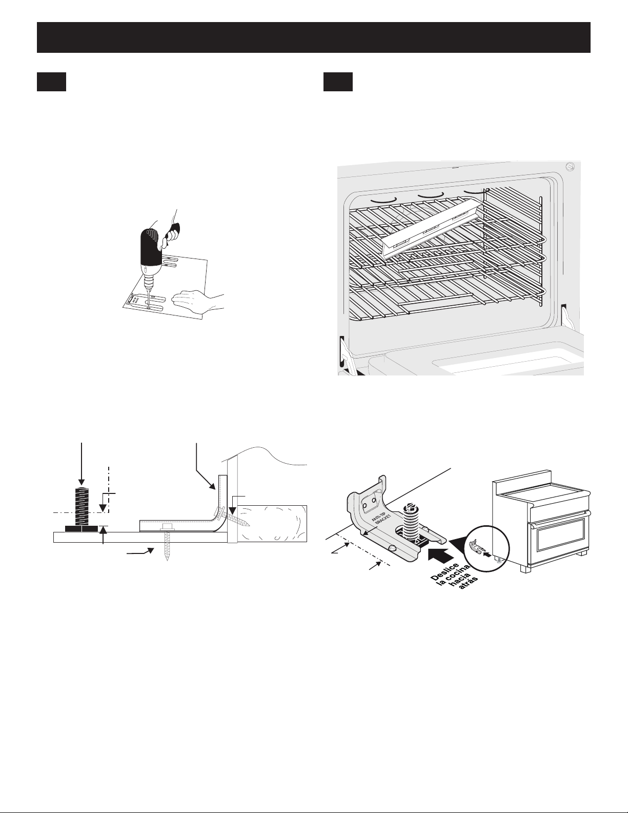
INSTRUCCIONES DE INSTALACIÓN DE LA COCINA DE DOBLE COMBUSTIBLE DE 40"
Pata niveladora
Montaje en el suelo
Soporte antivuelco
8.2
Perforación de agujeros piloto y jación
del soporte
Perfore un agujero piloto de 3 mm (1/8") en el lugar en que
se vayan a situar los tornillos.
Si el soporte se va a instalar en la pared, perfore el
agujero piloto con una inclinación aproximada de 20º hacia
abajo. Si el soporte se coloca sobre albañilería o suelos
cerámicos, perfore un agujero piloto de 4,8 mm (3/16") con
una profundidad de 44 mm (1-3/4").
Figura 15: Perfore los agujeros piloto
Los tornillos suministrados se pueden utilizar en madera
u hormigón. Use una llave de tuercas de 8 mm (5/16”)
o un destornillador de cabeza plana para sujetar el soporte
en su sitio.
8.3
Nivelación y colocación de la cocina
Compruebe la nivelación de la instalación nal. Nota: para
dejar espacio para el soporte, entre la parte inferior de la
cocina y la pata niveladora debe existir una separación de
3 mm (1/8"). Utilice un nivel para comprobar los ajustes.
Figura 17: Utilice las parrillas del horno para nivelar
el electrodoméstico
3 mm (1/8") mínimo
Figura 16: Sujeción del soporte
Deslice la cocina hasta colocarla en su posición.
Montaje en la
pared
Placa de
pared
Lateral de
la cocina
Figura 18: Deslice el electrodoméstico dentro
del soporte
Para comprobar si el soporte antivuelco se ha
instalado correctamente, sostenga con ambas
manos el borde posterior de la parte trasera de la
cocina. Con cuidado, trate de inclinarla hacia delante.
Si está instalada correctamente, no se inclinará.
Si se desplaza la cocina a otra ubicación, también se
deben instalar de nuevo los soportes antivuelco.
29
Page 30
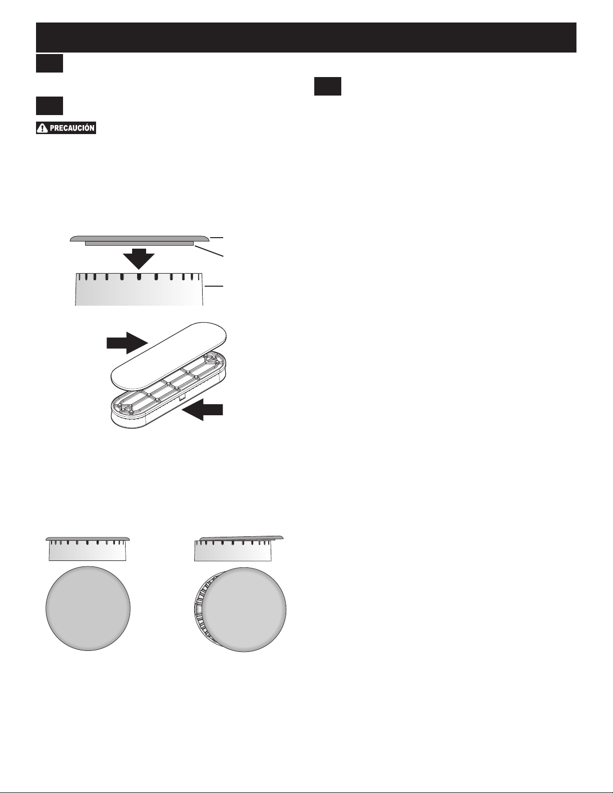
INSTRUCCIONES DE INSTALACIÓN DE LA COCINA DE DOBLE COMBUSTIBLE DE 40"
9
Preparación de los conjuntos
de quemador
9.1
Colocación de las tapetas
Para evitar llamaradas, utilice la placa de
cocción con todas las tapetas colocadas correctamente.
1. Coloque una tapeta en cada cabezal quemador
haciendo coincidir el tamaño de la tapeta con el
del cabezal (ver gura 19). Cada tapeta dispone de
un anillo interior de posicionamiento que la centra
correctamente sobre el cabezal.
2. Asegúrese de que todas las tapetas estén
Tapeta
Aro de posicionamiento
Cabezal
quemador
Tapeta
9.2
Comprobación del encendido
de los quemadores
Después de haber vericado minuciosamente si
la cocina y conectores de la tubería de suministro
tienen fugas y de conectar el electrodoméstico a
la alimentación eléctrica, se debe comprobar el
funcionamiento de los encendedores eléctricos.
Para comprobar si el encendido es correcto:
1. Gire y presione hacia dentro la perilla del quemador
a posición de chispa. Todos los encendedores
electrónicos generarán chispas al mismo tiempo.
Solo se encenderá el quemador que esté activando.
2. El quemador de supercie se debe encender
cuando el ujo de gas haya llegado al quemador.
Un quemador se debe encender a los cuatro
segundos de funcionamiento normal después de
haber purgado el aire de las tuberías de suministro.
Compruebe visualmente si se enciende el quemador.
3. Cuando ya esté encendido, la perilla de control se
debe quitar de la posición LITE.
Encienda cada uno de los quemadores y compruebe
si lo hacen correctamente y que la llama sea uniforme.
Realice los ajustes necesarios.
Cabezal
quemador
Figura 19: Conjunto de quemador y tapeta
debidamente alineadas y niveladas como se muestra
en la gura 20. Si no se colocan correctamente en el
cabezal, es posible que el quemador no se encienda
o queme de forma irregular.
Correcto Incorrecto
Figura 20: Colocación de la tapeta
30
Page 31
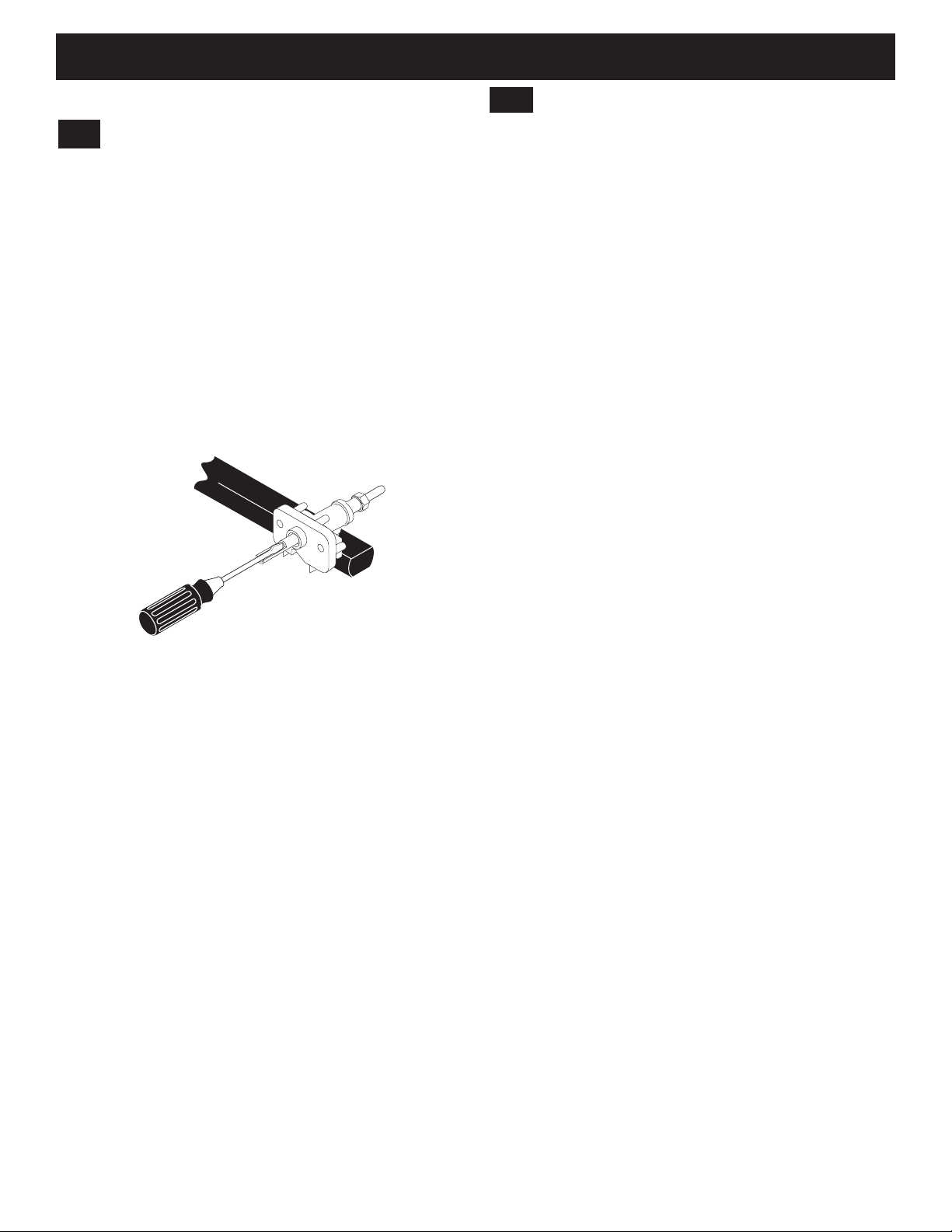
INSTRUCCIONES DE INSTALACIÓN DE LA COCINA DE DOBLE COMBUSTIBLE DE 40"
Comprobación del
10
9.3
Regulación del ajuste inferior de
los quemadores
Para regular el ajuste inferior de los quemadores:
1. Gire y presione hacia dentro la perilla de control a
posición LITE hasta que se encienda el quemador.
2. Gire rápidamente la perilla a la POSICIÓN MÁS BAJA.
3. Si se apaga el quemador, ponga el control en OFF.
4. Quite la perilla de control del quemador
correspondiente y el aro decorativo.
5. Introduzca un destornilador estrecho por el vástago
hueco de la válvula y acóplelo al tornillo ranurado
interior como se muestra en la gura 21. El tamaño
de la llama se aumenta o reduce girando el tornillo.
Figura 21: Girar para ajustar la llama
6. Regule la llama hasta que pueda girar rápidamente
la perilla desde posición de chispa hasta posición de
llama más baja sin que se apague la llama La llama
debe ser lo más pequeña posible sin que se apague.
Notas:
• En quemadores de supercie no es necesario ajustar
la mezcla de aire.
• Algunos modelos tienen dos llamas en un mismo
quemador. La llama central de estos quemadores
no se puede regular.
funcionamiento del horno
Consulte la guía de uso y cuidado que se entrega
con la cocina para conocer las instrucciones de
funcionamiento, cuidado y limpieza.
Extraiga todo el material de embalaje del horno antes
de probarlo.
El horno está provisto de un control electrónico. Cada
una de las funciones ha sido comprobada en fábrica
antes del envío. Sin embargo, se sugiere vericar
una vez más el funcionamiento de los controles
electrónicos. Consulte la guía del propietario para
conocer su funcionamiento. Siga las instrucciones
para las funciones de reloj, temporizador, hornear,
asar, convección y limpieza.
Hornear -Después de ajustar el horno a 177 °C (350 ºF)
para hornear, el suelo de la cavidad del horno debe
empezar a calentarse.
Asar -Cuando el horno se ajusta en BROIL (ASAR),
el elemento superior del horno debe ponerse rojo.
Limpiar -Cuando el horno se ajusta para un ciclo de
autolimpieza, el elemento superior debe ponerse rojo
durante la fase de precalentamiento del ciclo. Después
de alcanzar la temperatura de autolimpieza, el suelo
de la cavidad del horno debe estar caliente.
Convección -Cuando el horno se ajusta en CONV.
BAKE/ROAST (HORNEAR/ASAR CON CONVECCIÓN)
a 177 °C (350 ºF), ambos elementos activan y
desactivan su ciclo alternativamente y gira el ventilador
de convección. El ventilador de convección dejará
de girar cuando se abra la puerta del horno durante
un ciclo de horneado o asado con convección.
31
Page 32
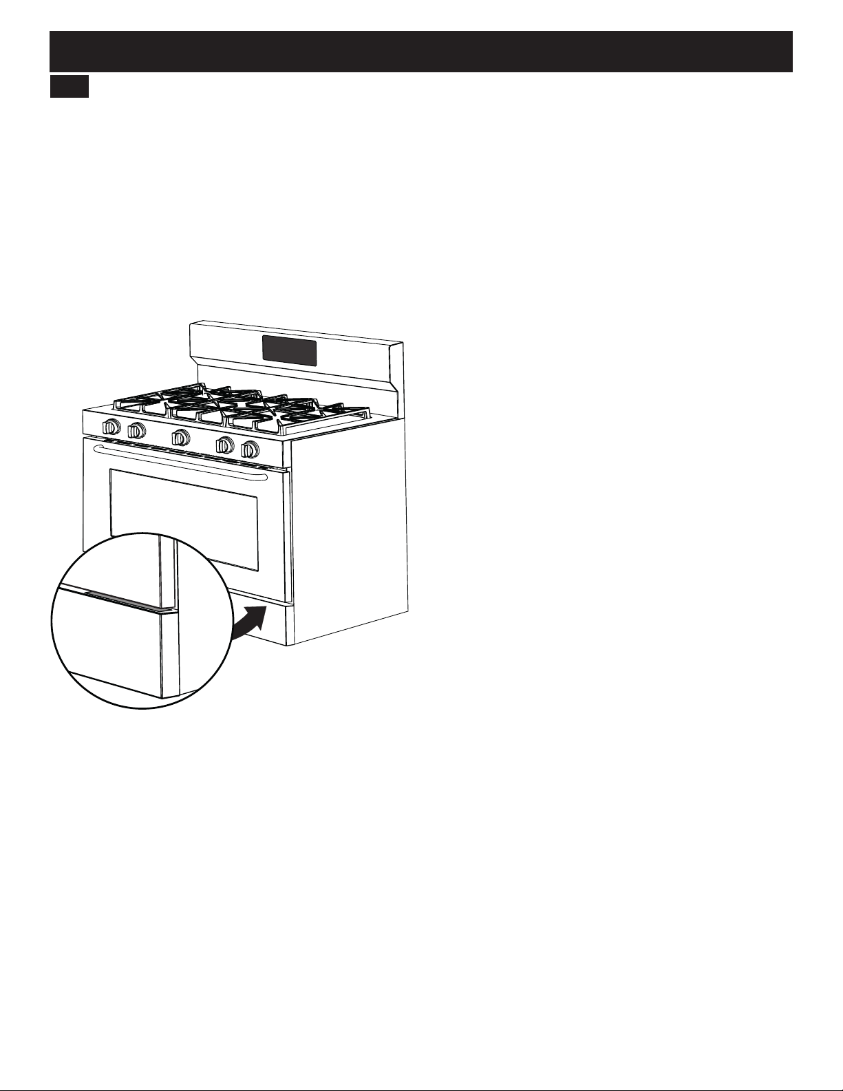
INSTRUCCIONES DE INSTALACIÓN DE LA COCINA DE DOBLE COMBUSTIBLE DE 40"
Después de la instalación
11
Cuando estén completadas todas las conexiones
Asegúrese de que todos los controles estén a la
izquierda en posición OFF.
Ubicación del número de modelo y de serie
La placa con los datos está situada en la parte superior
del panel frontal inferior de la cocina; se puede ver
con claridad cuando la puerta está abierta. Cuando se
realice el pedido de piezas o se hagan consultas sobre
la cocina, tenga preparados los números de modelo
y serie (Figura 22).
Figura 22: Ubicación del número de modelo y de serie
Antes de solicitar servicio técnico
Lea la 'Lista de comprobación para evitar el servicio
técnico' y las instrucciones de funcionamiento en la
guía del propietario. Su lectura puede hacer que ahorre
tiempo y dinero. La lista incluye problemas comunes
que no son resultado de mano de obra o materiales
defectuosos en este electrodoméstico.
Consulte la información de garantía y servicio técnico de
la guía del propietario para conocer nuestro número de
teléfono y dirección. Llámenos por teléfono o escríbanos
sus consultas sobre la cocina y/o si necesita pedir
piezas.
32
 Loading...