

Page 1

All about the
Installation
of your Washer
TABLE OF CONTENTS
Important Safety Instructions ...........................2-3
Installation Requirements ................................4-6
Installation Instructions ................................... 7-9
Accessories ...................................................... 10
Français ........................................................... 11
Español ........................................................... 21
A00092401C (1306)
Page 2
IMPORTANT SAFETY INSTRUCTIONS
WARNING
Please read all instructions before using this washer.
Recognize safety symbols, words
and labels
Safety items throughout this manual are labeled with
a WARNING or CAUTION based on the risk type as
described below:
Defi nitions
This is the safety alert symbol. It is used to alert
you to potential personal injury hazards. Obey all safety
messages that follow this symbol to avoid possible injury
or death.
DANGER
DANGER indicates an imminently hazardous situation
which, if not avoided, will result in death or serious
injury.
WARNING
WARNING indicates a potentially hazardous situation
which, if not avoided, could result in death or serious
injury.
CAUTION
CAUTION indicates a potentially hazardous situation
which, if not avoided, may result in minor or moderate
injury.
IMPORTANT
IMPORTANT indicates installation, operation or
maintenance information which is important but not
hazard-related.
Installation Checklist
Shipping Hardware
Foam shipping restraint (inside wash tub)
removed and stored
Foam shipping support (underneath tub inside
cabinet) removed and stored
Leveling
Washer is level, side-to-side and front-to-back
Cabinet is setting solid on all corners
Water Supply
Use only new hoses and verify rubber sealing
washers are installed
HOT supply is connected to HOT inlet and
COLD supply is connected to COLD inlet
HOT and COLD water supply turned on
No leaks present at water supply connections
or appliance inlet connections recheck in 24 hours
Drain
Stand pipe or wall drain height minimum 36”
Drain hose secured in place with cable tie
(shipped in drum)
Electrical Power
House power turned on
Washer plugged in
Final Checks
Installation Instructions
Guide
read thoroughly
Water enters drum when cycle starts with lid
lowered.
Registration card sent in
and
Use and Care
2
Page 3
IMPORTANT SAFETY INSTRUCTIONS
NOTE
The electrical service to the washer must conform with
local codes and ordinances and the latest edition of the
National Electrical Code, ANSI/NFPA 70, or in Canada,
the Canadian Electrical Code C22.1 part 1.
WARNING
For your safety the information in this manual must be
followed to minimize the risk of fi re or explosion or to
prevent property damage, personal injury or loss of life.
Do not store or use gasoline or other fl ammable vapors
and liquids in the vicinity of this or any other appliance.
FIRE HAZARD
WARNING
Destroy the carton and plastic bags after the washer is
unpacked. Children might use them for play . Cartons
covered with rugs, bedspreads, or plastic sheets can
become airtight chambers causing suffocation. Place
all materials in a garbage container or make materials
inaccessible to children.
SUFFOCATION HAZARD
CAUTION
To avoid back or other injury, have more than one
person move or lift the washer.
EXCESSIVE WEIGHT HAZARD
IMPORTANT
The instructions in this manual and all other literature
included with this washer are not meant to cover
every possible condition and situation that may occur.
Good safe practice and caution MUST be applied when
installing, operating and maintaining any appliance.
Maximum benefi ts and enjoyment are achieved
when all the Safety and Operating Instructions are
understood and practiced as a routine with your
laundering tasks.
Save these instructions for future reference.
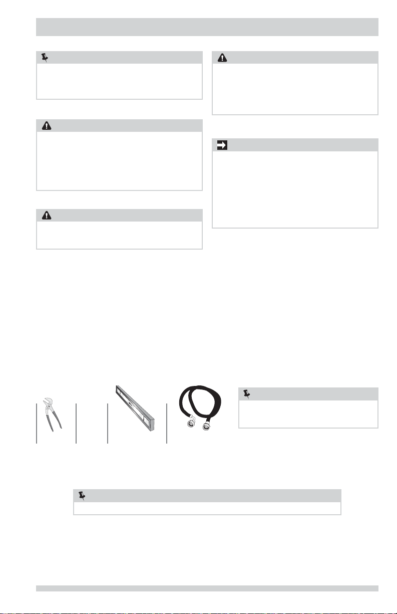
Tools and materials needed for installation:
AND
Adjustable
pliers
Carpenter’s level
NOTE
Before beginning installation, tip unit back and verify foam tub support has been removed.
Inlet hose (x2)
NOTE
Hoses are not included with washer purchase.
See “Accessories” section for various inlet
hose kits to fi t your specifi c installation.
3
Page 4
INSTALLATION REQUIREMENTS
Grounding type
ll receptacle
wer cord with
3-prong grgr
ounded plug
Do not,
under
y cir
cumstances,
cut,
removeve,
or b
ypass the
ounding pr
ong.
Electrical system requirements Ground requirements
CIRCUIT - Individual, properly polarized and grounded
15 amp. branch circuit fused with 15 amp. time delay
fuse or circuit breaker.
POWER SUPPLY - 2 wire, with ground, 120 volt single
phase, 60 Hz, Alternating Current.
NOTE
Because of potentially inconsistent voltage capabilities,
the use of this washer with power created by gas
powered generators, solar powered generators, wind
powered generators or any other generator other than
the local utility company is not recommended.
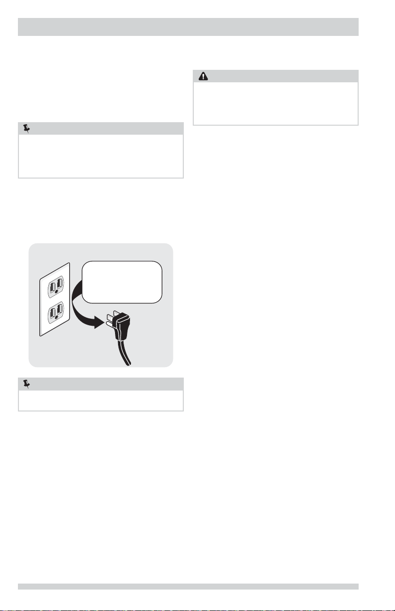
OUTLET RECEPTACLE - Properly grounded 3-prong
receptacle to be located so the power supply cord
is accessible when the washer is in an installed
position.
Grounding type
wawall receptacl
Do not,
under
anany cir
cumstances,
cut,
remo
or b
ypass th
grgrounding pr
ong.
WARNING
Improper connection of the equipment grounding
conductor can result in a risk of electrical shock. Check
with a licensed electrician if you are in doubt as to
whether the appliance is properly grounded.
1 The washer MUST be grounded. In the event of
2 Since your washer is equipped with a power supply
ELECTRICAL SHOCK HAZARD
malfunction or breakdown, grounding will reduce the
risk of electrical shock by a path of least resistance
for electrical current.
cord having an equipment-grounding conductor
and a grounding plug, the plug MUST be plugged
into an appropriate, copper wired receptacle that is
properly installed and grounded in accordance with
all local codes and ordinances or in the absence of
local codes, with the National Electrical Codes, ANSI/
NFPA 70 (latest edition). If in doubt, call a licensed
electrician. DO NOT cut off or alter the grounding
prong on the power supply cord. In situations where
a two-slot receptacle is present, it is the owner’s
responsibility to have a licensed electrician replace
it with a properly grounded three prong grounding
type receptacle.
PoPower cord with
3-prong
ounded plug
NOTE
GFI (Ground Fault Interrupter) receptacle is not
required.
4
Water supply requirements
Hot and cold water faucets MUST be 3/4 inch with
threading for laundry hose connection. Water pressure
MUST be between 30 and 120 psi. Pressure difference
between hot and cold cannot be more than 10 psi. Your
water department can advise you of your water pressure.
Page 5
INSTALLATION REQUIREMENTS
Drain system requirements
1 Drain capable of eliminating 17 gals (64.3 L) per
minute.
2 A standpipe diameter of 1-1/4 in. (3.18 cm)
minimum.
3 The standpipe height above the fl oor should be:
Minimum height: 36 in. (91 cm)
Maximum height: 96 in. (244 cm)
96”
(244 cm)
max.
36”
(91 cm)
min.
NOTE
For installations requiring a longer drain hose, have
a qualifi ed technician install a longer drain hose
(according to your model number) available from an
authorized parts distributor. For drain systems in the
fl oor, install a syphon break kit available from your local
hardware store.
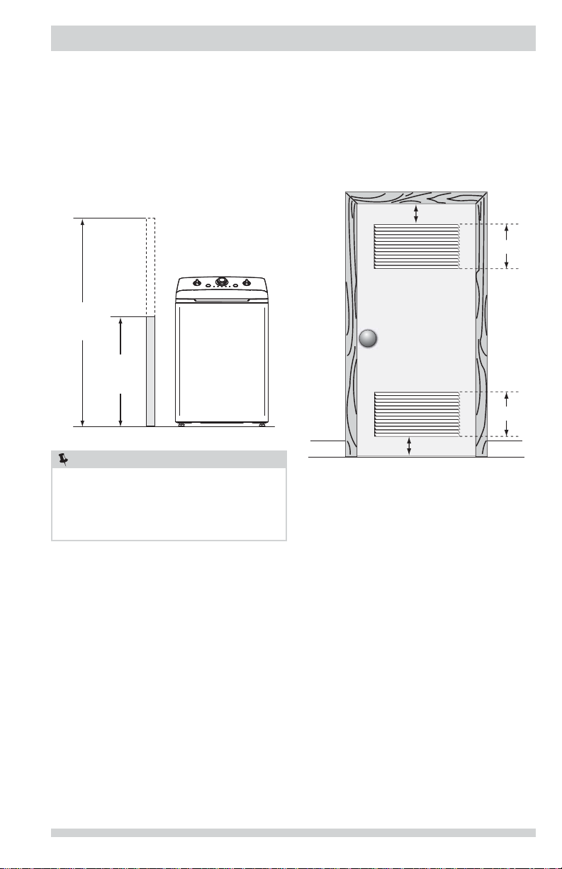
Installation in a Recess or Closet
If washer and dryer are installed in the same closet, door
ventilation is required: A minimum of 120 square inches
(774.2 cm²) of opening, equally divided at the top and
bottom of the door, is required. Louvered openings should
be located 3 inches (7.6 cm) from bottom and top of
door. Air openings are required to be unobstructed when
a door is installed. A louvered door with equivalent air
openings for the full length of the door is acceptable.
3”
(7.6cm)
60 sq. in.
(387.1cm²)
60 sq. in.
(387.1cm²)
3”
(7.6cm)
closet door
5
Page 6
INSTALLATION REQUIREMENTS
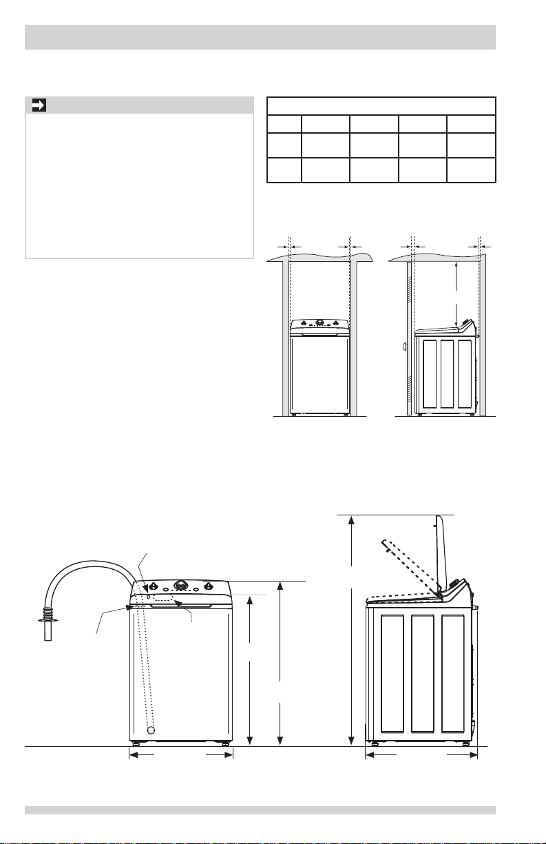
Clearance requirements
IMPORTANT
DO NOT INSTALL YOUR WASHER:
1 In an area exposed to dripping water or outside
weather conditions. The ambient temperature
should never be below 60° F (15.6° C) to
maximize detergent effectiveness.
2 In an area (garage or garage-type building)
where gasoline or other fl ammables (including
automobiles) are kept or stored.
3 On carpet. Floor MUST be solid with a maximum
slope of 1 inch (2.5 cm). To minimize vibration
or movement, reinforcement of the fl oor may be
necessary.
Washer Dimensions
MINIMUM INSTALLATION CLEARANCES - Inches (cm)
SIDES REAR TOP FRONT
Alcove
Closet
(0 cm)
(0 cm)
(0 cm)0”(0 cm)
0”
0”
(0 cm)
0”
(0 cm)
0”
0”
20.5”
(52 cm)
20.5”
(52 cm)1”(2.5 cm)
1”
(2.5 cm)
20.5”
(52 cm)
n/a
0”
(0 cm)
power cord attachment
location on rear of unit
drain hose
retainer on rear
2
of washer
1
Power supply cord length approximately 60 inches (152.5 cm).
2
Loose drain hose length beyond hose retainer approximately 61 inches (155 cm).
water supply
connection on
rear of washer
26.25” (67 cm)
1
38.5”
(98 cm)
(107 cm)
6
59” (150 cm)
to clear open lid
42”
28.75” (78 cm)
Page 7
INSTALLATION INSTRUCTIONS
Leveling your washer
Excessive noise and vibration can be prevented by
properly leveling the washer.
1 With the washer within 4 feet (1 m) of its fi nal
location, use a carpenter’s level to level your
washer front-to-back and side-to-side. For front-toback leveling, place edge of the level fl ush to the
front panel. For side-to-side leveling place the edge
of the level fl ush to the side panel.
2 Use adjustable pliers to adjust the leveling legs so
the washer is level front-to-rear and side-to-side,
and stable corner-to-corner.
3 Press down on alternate corners and sides and feel
for the slightest movement. Adjust the appropriate
leg(s) so the washer sits solidly on the fl oor on
ALL four legs. Keep the leveling leg extension at a
minimum for best performance of the washer.
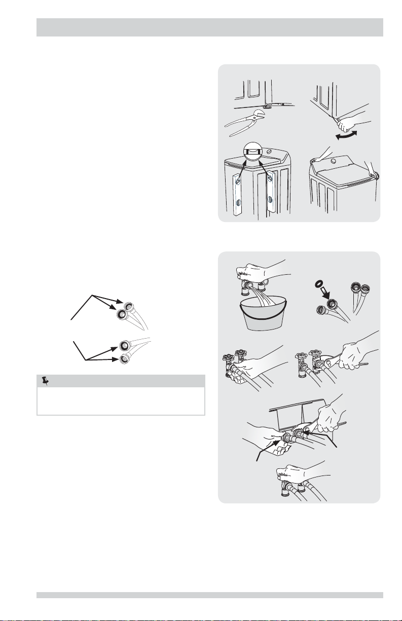
Connecting inlet water
1 Run some water from the hot and cold faucets
to fl ush the water lines and remove particles
that might clog the water valve screens and to
determine which faucet is hot and which is cold
supply.
a
c
a
b
raise
d
lower
b
RUBBER WASHERS
MUST BE PRESENT
USE ONLY
NEW HOSES
NOTE
Hoses are not included with washer purchase. See
“Accessories” section for various inlet hose kits to fi t
your specifi c installation.
2 Connect the HOT inlet hose to the HOT inlet
connection on the washer and the COLD inlet
hose to the COLD inlet connection on the washer.
Tighten by hand until snug. Then tighten each
supply connection another 2/3 turn with pliers.
Do not cross thread or over-tighten these
connections.
3 Connect the HOT inlet hose to the HOT water
supply and the COLD inlet hose to the COLD water
supply. Tighten by hand until snug. Then tighten
each supply connection another 2/3 turn with
pliers. Do not bend, kink or pinch water inlet
hoses.
4 Turn on the water and check for leaks.
e
BLUE
(COLD)
c
g
d
f
RED
(HOT)
7
Page 8
INSTALLATION INSTRUCTIONS
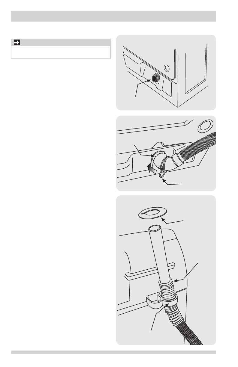
Connecting drain hose to washer
IMPORTANT
Inspect rubber fl ap on pump outlet. Ensure it is in
place and not folded under or torn.
1 With the spring clamp already installed, place
the drain hose elbow over the pump outlet at the
lower rear of the washer. Ensure the hose elbow is
completely and squarely seated to the pump outlet
before using pliers to move the spring clamp into
place.
DRAIN PUMP
OUTLET
SLIDE CLAMP
TO HERE
SPRING CLAMP
2 “Thread” the end of the drain hose up through
either of the outer, larger “D” ring retainers below
the top panel.
3 Locate the anti-siphon ring shipped with your
washer. Place it over the end of the drain hose and
slide it past the fi rst ring of “accordion” ribs.
8
ANTI-SIPHON
DISC
SLIDE DISC
TO HERE
DRAIN HOSE
RETAINER
Page 9
INSTALLATION INSTRUCTIONS
Grounding type
ll receptacle
wer cord with
3-prong grgr
ounded plug
Do not,
under
y cir
cumstances,
cut,
removeve,
or b
ypass the
ounding pr
ong.
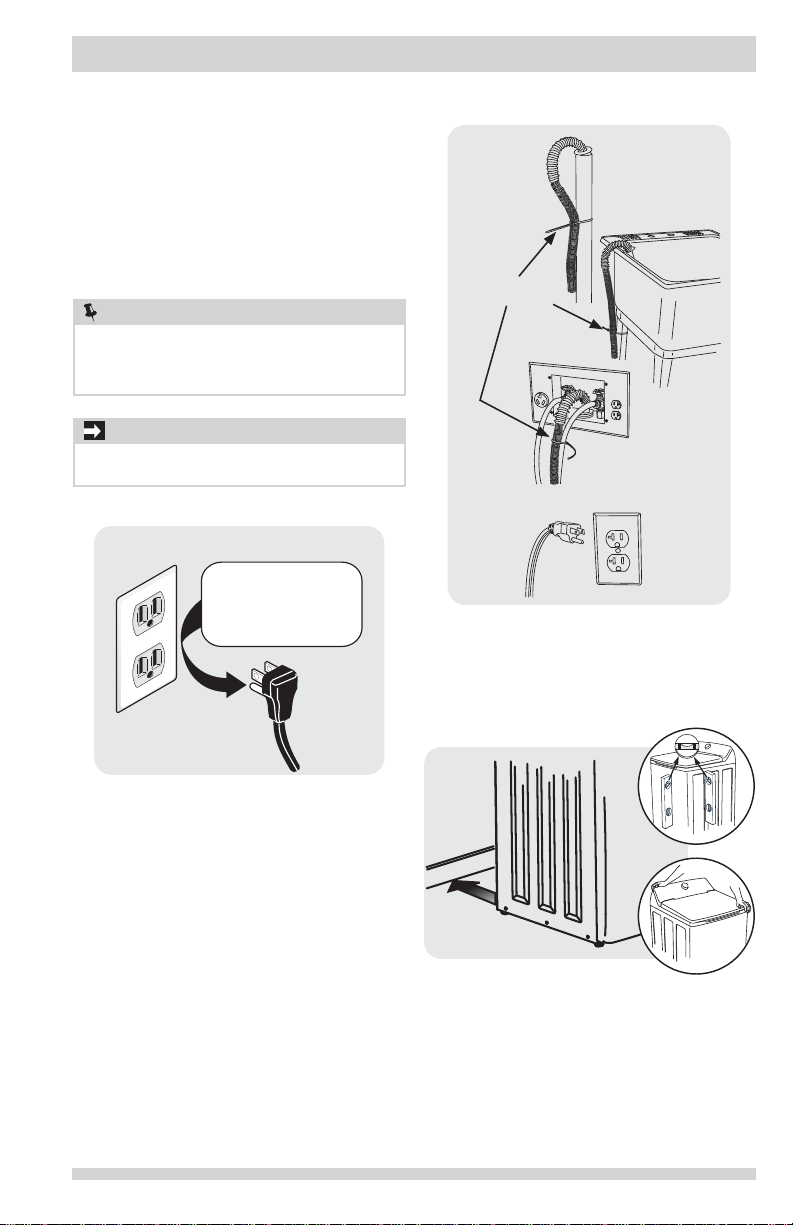
Connecting drain and electrical
1 Form a “U” shape on the end of the drain hose
with the hose pointed toward the drain. Place the
formed end in a laundry tub or a standpipe and
secure with a cable tie provided in the enclosure
package.
2 Place the hook end of the drain hose in the drain
opening. Secure the drain hose with the cable
tie (provided in the enclosure package) to the
standpipe, inlet hose, laundry tub, etc. so the hose
does not pull out from the force of the water.
NOTE
The standpipe inside diameter must be 1-1/4” (3.2 cm)
minimum. There must be an air gap around the drain
hose in the standpipe. A snug hose fi t can cause a
siphoning action.
IMPORTANT
Check to ensure the power is off at a circuit breaker/
fuse box before plugging the power cord into an outlet.
3 Plug the power cord into a grounded outlet.
Grounding type
wawall receptacl
Do not,
under
anany cir
cumstances,
cut,
remo
or b
ypass th
grgrounding pr
ong.
CABLE TIE
PoPower cord with
3-prong
4 Turn on the power at the circuit breaker/fuse box.
5 Carefully slide the washer to its fi nal position.
Recheck for level and rock corners for stability.
6 Read the
washer. It contains valuable and helpful information
that will save you time and money.
7 Run the washer through a complete cycle, checking
for water leaks and proper operation.
8 If you have any questions during initial operation,
please review the “Avoid Service Checklist” in your
Use & Care Guide before calling for service.
9 Place these instructions in a location near the
appliance for future reference.
Use & Care Guide
ounded plug
provided with the
9
Page 10
ACCESSORIES
MOBILE HOME INSTALLATION KIT
P/N 137067200
Installation in a mobile home requires the use of a
MOBILE HOME INSTALLATION KIT.
INLET HOSE KITS
Please call 866-233-8353 (in Canada, 800-265-8352)
to explore hose kit options that will meet your specifi c
installation needs.
UNIVERSAL APPLIANCE WRENCH
P/N 137019200
A UNIVERSAL APPLIANCE WRENCH is available to aid in
dryer/washer feet adjustment.
TOUCH UP PAINT PENS*
Classic White Touch Up Pen - P/N 5304468812
*Other colors may be available. Contact the source where you
purchased your washer.
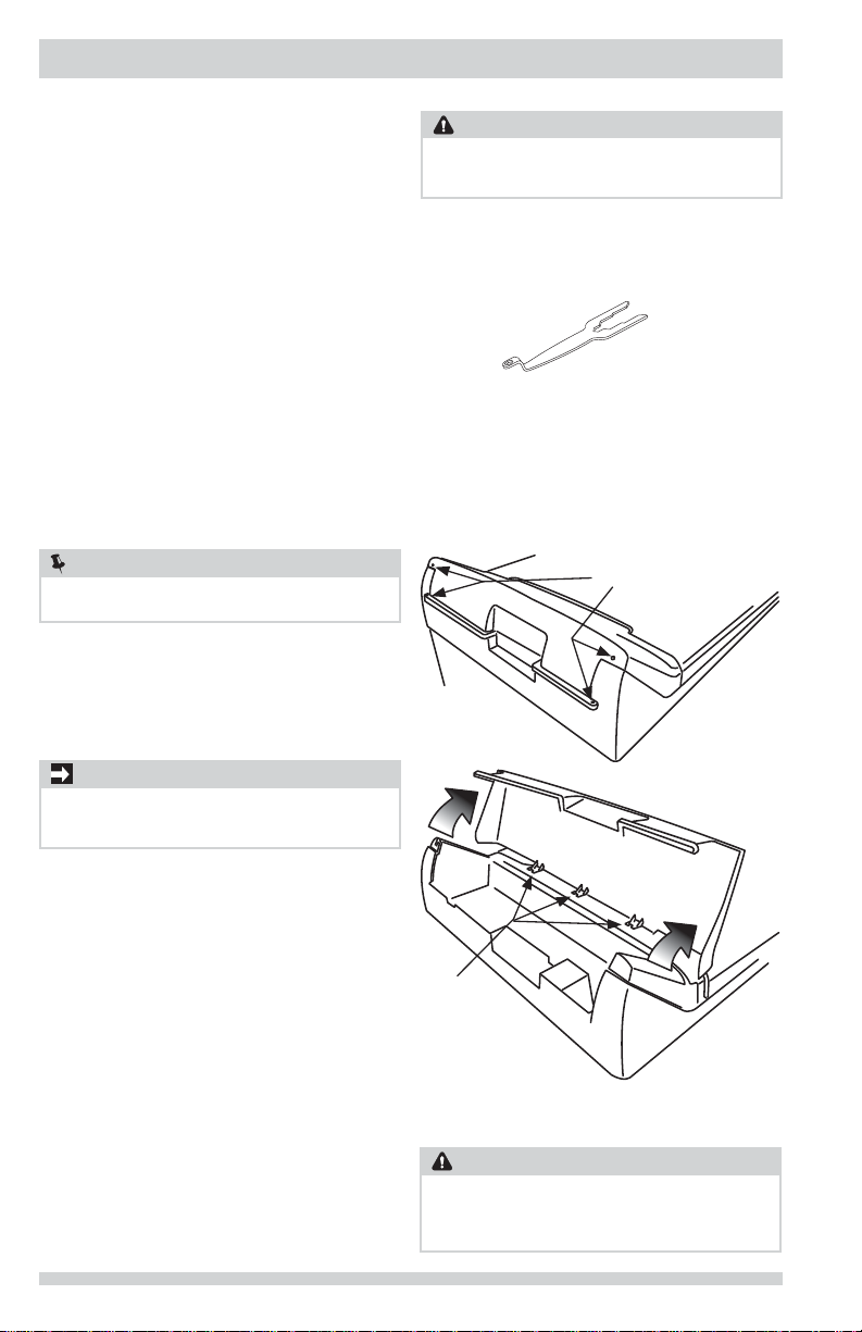
Technical Sheet/Wiring Diagram:
NOTE
A wiring diagram and technical data sheet are located
inside the washer console.
To remove the console faceplate follow the directions
below:
1. Disconnect washer from electrical source.
2. Remove four screws on back of the console housing.
3. Slowly rotate console forward on hinge tabs.
IMPORTANT
Internal parts of console are attached with wires to the
washer. Prevent machine damage. Do NOT pull console
away from washer.
4. When fi nished with repair, return sheet inside console
and ensure hinge tabs are inserted in top panel.
Gently rotate console back and reinsert all four screws.
CAUTION
Failure to use accessories manufactured by (or approved
by) the manufacturer could result in personal injury,
property damage or damage to the washer.
CONSOLE SCREWS
Replacement parts:
If replacements parts are needed for your washer, contact
the source where you purchased your washer or refer to
your
Use and Care Guide
for more information.
10
HINGE TABS
WARNING
Label all wires prior to disconnection when servicing
controls. Wiring errors can cause improper and dangerous
operation. Verify proper operation after servicing.
ELECTRICAL SHOCK HAZARD
Page 11

Tout à propos de
Installation
de votre Laveuse
TABLE DES MATIÈRES
Mesures de sécurité importantes ...................12-13
Exigences d’installation .................................14-16
Instructions d’installation ..............................17-19
Accessoires ...................................................... 20
Page 12

MESURES DE SÉCURITÉ IMPORTANTES
AVERTISSEMENT
Veuillez lire ces instructions au complet avant d’utiliser
le laveuse.
Sachez reconnaître les symboles, les
avertissements et les étiquettes de
sécurité.
Les mesures de sécurité présentées dans ce guide sont
identifi ées par le mot AVERTISSEMENT ou ATTENTION
selon le type de risque présenté ci-dessous.
Défi nitions
Voici le symbole d’avertissement concernant la
sécurité. Il est utilisé pour vous avertir des risques de
blessures potentiels. Respectez tous les messages qui
suivent ce symbole afi n de prévenir les blessures ou la
mort.
DANGER
La mention DANGER indique un risque imminent qui
causera la mort ou de graves blessures, s’il n’est pas
évité.
AVERTISSEMENT
La mention AVERTISSEMENT indique une situation
potentiellement dangereuse qui, si elle n’est pas évitée,
pourrait entraîner des blessures graves ou même la mort.
ATTENTION
La mention AT TENTION signale la présence d’une
situation potentiellement dangereuse susceptible de
causer des blessures mineures ou moyennement graves
si elle n’est pas évitée.
IMPORTANT
IMPORTANT - Cette mention précède des renseignements
importants relatifs à l’installation, au fonctionnement ou à
l’entretien. Toutef ois, ceux -ci n’impliquent aucune notion
de danger.
Liste de vérifi cation d’installation
Matériel d’expédition
Le bloc de retenue en mousse (situé dans la
cuve de lavage) a été enlevé et remisé
Le support d’expédition en mousse (sous
l’appareil) a été enlevé et remisé
Mise à niveau
La laveuse est au niveau latéralement et de
l’avant vers l’arrière
Les quatre coins de la caisse reposent
fermement sur le plancher
Alimentation en eau
Utilisez seulement les nouveaux tuyau
d’entrée d’eau et vérifi er que les rondelles en
caoutchouc sont en place.
Le tuyau d’entrée d’eau CHAUDE est raccordé
au robinet d’eau CHAUDE et le tuyau d’entrée
d’eau FROIDE est raccordé au robinet d’eau
FROIDE
Les robinets d’eau CHAUDE et d’eau FROIDE
sont ouverts
Les raccords d’alimentation en eau ou les
raccords d’arrivée d’eau de l’appareil ne
présentent aucune fuite refaites une vérifi cation 24 heures plus tard
Tuyau de vidange
La colonne montante ou le drain de mur est à
une hauteur d’au moins 91 cm (36 po)
Le tuyau de vidange est fi xé avec l’attache
(incluse dans la cuve)
Alimentation en électricité
Le système électrique de la maison est sous
tension
La laveuse est branchée
Vérifi cations fi nales
Vous avez lu entièrement les
d’installation
d’entretien
La porte se verrouille et l’eau entre dans la
cuve lorsqu’un cycle démarre
La carte d’enregistrement est envoyée
et le
Guide d’utilisation et
instructions
12
Page 13

MESURES DE SÉCURITÉ IMPORTANTES
REMARQUE
L’installation électrique de la laveuse doit être conforme
aux codes et aux règlements locaux ainsi qu’à la
toute dernière édition du National Electrical Code
(ANSI/NFPA 70), ou au Canada, au Code canadien de
l’électricité (C22.1, article 1).
AVERTISSEMENT
Détruisez le carton d’emballage et les sacs en plastique
après avoir déballé l’appareil. Les enfants pourraient
les utiliser pour jouer. Le carton recouvert de tapis, les
couvertures et les feuilles de plastique peuvent être
étanches à l’air et provoquer la suffocation. Déposez
tous les matériaux d’emballage dans un conteneur à
déchets ou faites en sorte que les enfants ne puissent
y avoir accès.
RISQUE D’ÉTOUFFEMENT
ATTENTION
Pour éviter les blessures au dos ou d’autres types de
blessure, demandez l’aide d’autres personnes pour
déplacer ou soulever la laveuse.
DANGER DE POIDS EXCESSIF
Conservez ces instructions pour vous
y reporter ultérieurement.
AVERTISSEMENT
Pour votre sécurité, l’information contenue dans ces
instructions doit être suivie afi n de réduire les risques
d’incendie ou d’explosion ou pour prévenir les dommages
matériels, les blessures ou la mort. Vous ne devez ni
entreposer, ni utiliser d’essence ou d’autres vapeurs ou
liquides infl ammables à proximité de cet appareil ou de
tout autre appareil électroménager.
RISQUE D’INCENDIE
IMPORTANT
Les instructions comprises dans ce guide et toute
autre documentation fournie avec cet appareil ne sont
pas conçues pour couvrir toutes les éventualités ou
situations qui pourraient survenir. Vous DEVEZ faire
preuve de bon sens et de prudence durant l’installation,
l’utilisation et l’entretien de tout appareil ménager.
Vous tirerez le maximum de votre appareil lorsque
toutes les instructions relatives à la sécurité et à son
fonctionnement auront été bien assimilées et mises en
pratique de façon routinière.
Outils et matériel nécessaires à l’installation :
ET
Pince
réglable
Niveau de charpentier
Tuyaux d’alimentation (x2)
REMARQUE
Avant de commencer l’installation unité de pointe, en arrière et vérifi er de support de cuve
en mousse a été éliminée.
REMARQUE
Les tuyaux ne sont pas inclus avec l’achat
laveuse. Voir la section «Accessoires» pour
divers trousse de tuyaux d’entrée qui pourrait
s’adapter à votre installation.
13
Page 14

EXIGENCES D’INSTALLATION
Prise murale avec
mise à la terre
à la terre de cette che.
Ne coupez pas, n'enlevez
pas et ne mettez pas hors
circuit la broche de mise
Cordon électrique muni
avec mise à la terre
d’une che à trois broches
Exigences des systèmes électriques Exigences relatives à la mise à la terre
CIRCUIT - Circuit indépendant de 15 ampères, polarisé
et mis à la terre, avec fusible temporisé ou
disjoncteur de 15 A.
ALIMENTATION ÉLECTRIQUE - Câble monophasé à deux
fi ls mis à la terre, 120 volts, 60 Hz; courant alternatif.
REMARQUE
Étant donné les variations de tension possibles, l’utilisation
de cette laveuse avec une source d’alimentation produite
par une génératrice à essence, solaire ou éolienne ou
par toute autre source d’alimentation différente de celle
fournie par les services publics n’est pas recommandée.
PRISE - Prise à trois alvéoles et mise à la terre située à
un endroit où il est possible de raccorder le cordon
d’alimentation de la laveuse une fois que cette
dernière est installée.
Prise murale avec
mise à la terre
Ne coupez pas, n'enlevez
pas et ne mettez pas hors
circuit la broche de mise
à la terre de cette che.
AVERTISSEMENT
RISQUE DE CHOC ÉLECTRIQUE
Un raccordement inadéquat du conducteur de terre de
l’équipement peut accroître les risques de choc électrique.
En cas de doute quant à la mise à la terre de l’appareil,
consultez un électricien qualifi é.
1 Cet appareil DOIT être mis à la terre. En cas de
mauvais fonctionnement ou de panne, la mise à
la terre diminue les risques de choc électrique en
fournissant au courant électrique une trajectoire de
moindre résistance.
2 Étant donné que votre laveuse est équipée d’un
cordon d’alimentation pourvu d’un conducteur de
mise à la terre et d’une fi che de mise à la terre, la
fi che DOIT être raccordée à une prise appropriée
(avec conducteurs en cuivre) correctement installée
et mise à la terre conformément aux codes et
règlements locaux ou, si aucun code local ne régit
ce type d’installation, à la plus récente édition du
National Electrical Code (ANSI/NFPA 70). En cas
de doute, faites appel à un électricien qualifi é. NE
COUPEZ PAS et NE MODIFIEZ PAS la broche de mise
à la terre du cordon d’alimentation. Si votre prise
murale n’est pourvue que de deux fentes, il incombe
au propriétaire de faire appel à un électricien qualifi é
pour la remplacer par une prise à trois alvéoles et
mise à la terre de façon adéquate.
Cordon électrique muni
d’une che à trois broches
avec mise à la terre
REMARQUE
Une prise GFI (disjoncteur de fuite de terre) n’est pas
nécessaire.
14
Exigences relatives à l’alimentation
en eau
Les robinets d’eau chaude et d’eau froide DOIVENT
être de 1,9 cm (3/4 po) et fi letés en fonction d’un
raccordement de tuyau de laveuse. La pression de l’eau
DOIT se situer entre 206,8 et 827,4 kPa (30 et 120 lb/
po²). La différence de pression entre l’eau chaude et
l’eau froide ne doit pas dépasser 68,9 kPa (10 lb/po²). Le
service des eaux de votre localité peut vous informer sur
la pression de votre alimentation en eau.
Page 15

EXIGENCES D’INSTALLATION
Exigences relatives au système
d’évacuation
1 Le drain doit pouvoir évacuer 64,3 L (17 gal) d’eau à
la minute.
2 Tuyau d’évacuation d’au moins 3,18 cm (1-1/4 po)
de diamètre.
3 Le tuyau d’évacuation doit être situé entre une
hauteur minimale de 91 cm (36 po) et une hauteur
maximale de 244 cm (96 po)
96”
(244 cm)
max.
36”
(91 cm)
min.
REMARQUE
Pour les installations exigeant un plus long tuyau
d’évacuation, demandez à un technicien qualifi é de
procéder à l’installation du tuyau conformément aux
spécifi cations du modèle de votre laveuse (un tuyau
plus long peut être acheté auprès d’un distributeur de
pièces autorisé). Pour les systèmes d’évacuation dans
le plancher, installez un ensemble de siphon (disponible
dans une quincaillerie de votre région).
Installation dans un Endroit en
Retrait ou une Armoire
Si la laveuse et la sécheuse sont installées dans le
même placard, une ventilation est requise dans la
porte : Une ouverture d’au moins 774,2 cm2 (120 po2),
divisée également au-dessus et au-dessous de la porte,
est requise. Les ouvertures à persiennes doivent être
situées à 7,6 cm (3 po) du haut et du bas de la porte.
Les ouvertures d’aération ne doivent pas être obstruées
lorsqu’une porte est installée. Une porte à persiennes
dont les ouvertures sur l’ensemble de la porte sont
équivalentes aux recommandations peut être utilisée.
3”
(7.6cm)
60 sq. in.
(387.1cm²)
60 sq. in.
(387.1cm²)
3”
(7.6cm)
Porte de placard
15
Page 16

EXIGENCES D’INSTALLATION
Exigences de dégagement
IMPORTANT
N’INSTALLEZ PAS VOTRE LAVEUSE :
1 À un endroit exposé aux écoulements d’eau
ou aux aléas des conditions météorologiques
extérieures. La température ambiante ne
devrait jamais tomber sous 15,6 °C (60 °F) afi n
d’optimiser l’effi cacité du détergent.
2 À un endroit (garage ou bâtiment similaire) où
de l’essence ou d’autres substances infl ammables
sont entreposées (incluant des automobiles).
3 Sur un tapis. Le plancher DOIT être solide et
présenter une pente inférieure à 2,5 cm (1 po).
Afi n d’éviter les vibrations et le déplacement de
l’appareil, il peut être nécessaire de renforcer le
plancher.
Dimensions de laveuse
DÉGAGEMENTS MINIMAUX - Centimètres (pouces)
CÔTÉS ARRIÈRE AVANT AVANT
Alcôve
Placard
(0 cm)
0 cm
(0 po)
0 cm
(0 po)
0”
0”
(0 cm)
0 cm
(0 po)
0 cm
(0 po)
52 cm
(20.5 po)
52 cm
(20.5 po)
1”
(2.5 cm)
20.5”
(52 cm)
s. o.
2.5 cm
(1 po)
(0 cm)
0”
cordon d’alimentation
à l’arrière de la laveuse
collier du tuyau de
vidange à l’arrière
de la laveuse
1
Longueur du cordon d’alimentation de la sécheuse à gaz, environ 152.5 cm (60 po).
2
Longueur du tuyau entre le collier et l’extrémité du tuyau, environ 155 cm (61 po).
2
raccord de
l’alimentation en
eau à l’arrière
de la laveuse
26.25” (67 cm)
1
38.5”
(98 cm)
42”
(107 cm)
16
59” (150 cm)
avec la couvercle
grande ouverte
28.75” (78 cm)
Page 17

INSTRUCTIONS D’INSTALLATION
Mise à niveau de votre appareil
Les bruits excessifs et les vibrations peuvent être évités
en mettant correctement la laveuse à niveau.
1 En plaçant la laveuse à 1 m (4 pi) de son
emplacement défi nitif, utilisez un niveau à bulle
pour mettre l’appareil à niveau de l’avant vers
l’arrière et latéralement. Pour mettre la laveuse
de l’avant vers l’arrière à niveau, bord la place du
niveau au ras du panneau frontal. Pour la mise à
niveau latérale, bord la place du niveau au ras du
panneau latérale.
2 Utilisez la clé universelle pour ajuster les pieds de
mise à niveau de façon à ce que la laveuse soit de
niveau d’avant en arrière et latéralement, et qu’elle
soit stable aux quatre coins.
3 Appuyez sur chaque coin et chaque côté pour
déterminer les endroits qui nécessitent un réglage.
Ajustez les pieds de mise à niveau appropriés de
manière à ce que la laveuse repose solidement
sur ses QUATRE pieds. Gardez les pieds de mise
à niveau le plus près possible de la laveuse afi n
d’optimiser le rendement de la laveuse.
a
c
b
soulever
d
abaisser
Branchement de l’entrée d’eau
1 Faites couler de l’eau chaude et froide des robinets
pour purger les tuyaux d’eau, pour éliminer
toute particule qui pourrait obstruer les grillages
des robinets, et pour déterminer quels robinets
fournissent l’eau chaude et l’eau froide.
LES RONDELLES
EN CAOUTCHOUC
DOIVENT ÊTRE
PRÉSENTES
UTILISEZ SEU-
LEMENT LES
NOUVEAUX
TUYAU D’EN-
TRÉE D’EAU
REMARQUE
Les tuyaux ne sont pas inclus avec l’achat laveuse. Voir
la section «Accessoires» pour divers trousse de tuyaux
d’entrée qui pourrait s’adapter à votre installation.
2 Raccordez le tuyau d’entrée d’eau CHAUDE au
raccord pour l’eau CHAUDE de la laveuse et le
tuyau d’entrée d’eau FROIDE au raccord pour l’eau
FROIDE de la laveuse. Serrez fermement à la main.
Avec des pinces, serrez chaque raccord de 2/3 de
tour. Ne faussez pas le fi letage et ne serrez
pas trop.
3 Branchez le tuyau d’entrée d’eau CHAUDE au
robinet d’eau CHAUDE, et le tuyau d’eau d’entrée
d’eau FROIDE au robinet d’eau FROIDE. Serrez
fermement à la main. Avec des pinces, serrez
chaque raccord de 2/3 de tour. Ne pliez pas,
n’entortillez pas et ne coincez pas les tuyaux
d’alimentation en eau.
4 Ouvrir les robinets et s’assurer qu’il n’y a pas de
fuite.
a
e
BLEU
(FROIDE)
b
c
g
d
(CHAUDE)
f
ROUGE
17
Page 18

INSTRUCTIONS D’INSTALLATION
Raccordement du boyau de vidange à la rondelle
IMPORTANT
Inspecter la bavette en caoutchouc sur l’orifi ce de
sortie de la pompe. S’assurer que celle-ci est en place
et qu’elle n’est pas pliée ou déchirée.
1 Avec le collier de serrage à ressort déjà installé,
placez le coude du tuyau de vidange sur le raccord
de sortie de la pompe sur le côté inférieur arrière
de la rondelle. S’assurer que le coude du boyau
est totalement et carrément assis à la sortie de
la pompe avant d’utiliser une paire de pince pour
mettre le collier de serrage à ressort en place.
SORTIE DE POMPE
DE VIDANGE
FAITES GLISSER
LE COLLIER ICI
COLLIER DE
SERRAGE À
RESSORT
2 « Fileter » l’extrémité du tuyau de vidange à travers
l’une ou l’autre des anneaux de retenue « D »
extérieurs, au-dessous du panneau supérieur.
3 Localiser l’anneau anti-siphon livré avec votre
lave-vaisselle. Placez-le sur l’extrémité du tuyau
de vidange et faites-le glisser au-delà du premier
anneau des nervures en « accordéon ».
18
DISQUE ANTI-
SIPHON
FAITES
GLISSER LE
DISQUE ICI
RETENUE DE BOYAU
DE VIDANGE
Page 19

INSTRUCTIONS D’INSTALLATION
Prise murale avec
mise à la terre
à la terre de cette che.
Ne coupez pas, n'enlevez
pas et ne mettez pas hors
circuit la broche de mise
Cordon électrique muni
avec mise à la terre
d’une che à trois broches
Branchement électrique et branchement du tuyau de vidange
1 Formez un U à l’extrémité du tuyau de vidange
avec le tuyau pointé vers la vidange. Placez
l’extrémité recourbée du tuyau de vidange dans
une cuve ou la conduite des eaux usées et fi xez-la
à l’aide d’un lien fourni dans le paquet.
2 Placez le côté du tuyau de vidange en forme de
crochet dans l’ouverture du tuyau d’évacuation.
Fixez le tuyau de vidange au moyen d’une attache
(incluse dans la trousse d’installation fournie) au
tuyau d’évacuation, au tuyau d’entrée, à la cuve à
lessive, etc. de façon à ce que le tuyau ne puisse
être arraché sous la force de l’eau.
REMARQUE
Le diamètre intérieur de la conduite verticale de
vidange doit être d’au moins 3,2 cm (1-1/4 po). Il doit
y avoir un brise-vide autour du tuyau de vidange de
la conduite verticale. Un tuyau au diamètre trop petit
peut entraîner un effet de siphonnage.
IMPORTANT
Assurez-vous que l’alimentation électrique est coupée au
disjoncteur ou au boîtier de fusibles avant de brancher le
cordon d’alimentation dans une prise électrique.
3 Branchez le cordon d’alimentation à la prise
électrique mise à la terre.
Prise murale avec
mise à la terre
Ne coupez pas, n'enlevez
pas et ne mettez pas hors
circuit la broche de mise
à la terre de cette che.
ATTACHE
Cordon électrique muni
d’une che à trois broches
avec mise à la terre
4 Ouvrez l’alimentation électrique au disjoncteur ou
au boîtier de fusibles.
5 Faites glisser soigneusement la laveuse à son
emplacement défi nitif. Vérifi ez à nouveau la stabilité
de l’appareil. Retirez et jetez le ruban de la porte.
6 Reportez-vous au Guide d’Utilisation et
d’Entretien fourni avec la laveuse. Il contient des
renseignements très utiles qui vous permettent
d’économiser temps et argent.
7 Faites faire un cycle complet à la laveuse. Vérifi ez
qu’il n’y a aucune fuite et que la laveuse fonctionne
correctement.
8 Pour toute question relative à l’utilisation initiale,
veuillez revoir la section intitulée « Liste de vérifi cation
avant service » de votre Guide d’utilisation et
d’entretien avant d’effectuer une demande de service.
9 Laissez ces instructions à proximité de l’appareil
pour vous y reporter ultérieurement.
19
Page 20

ACCESSOIRES
TROUSSE D’INSTALLATION DE MAISON MOBILE
PIÈCE N° 137067200
Toute installation dans une maison mobile nécessite
l’utilisation d’une TROUSSE D’INSTALLATION DE MAISON
MOBILE.
KITS TUYAUX D‘ALIMENTATION
S’il vous plaît appelez 866-233-8353 (au Canada, 800-
265-8352) pour explorer les options de tuyaux d’entrée
qui pourrait s’adapter à votre installation spécifi ques.
CLÉ D’APPAREIL UNIVERSELLE
PIÈCE N° 137019200
UNE CLÉ D’APPAREIL UNIVERSELLE est offerte pour
faciliter le réglage des pieds de sécheuse ou laveuse.
CRAYONS DE PEINTURE DE RETOUCHE*
Crayon de retouche Blanc - PIÈCE N° 5304468812
*Il se peut que d’autres couleurs soient disponibles.
Communiquez avec le marchand qui vous a vendu votre laveuse.
Fiche Technique/Schéma Électrique:
REMARQUE
Un schéma électrique et une fi che technique sont
situés à l’intérieur de la console de l’appareil.
Pour enlever la plaque avant de la console, suivez les
instructions ci-dessous :
1. Débranchez la laveuse de sa source d’alimentation en
électricité.
2. Retirer les quatre vis à l’arrière du boîtier de la console.
3. Faites pivoter lentement vers l’avant de la console sur
languettes de charnière.
ATTENTION
Tout défaut d’utiliser les accessoires fabriqués ou
certifi és par le fabricant pourrait entraîner des blessures,
des dommages aux biens ou à la laveuse.
VIS DE LA CONSOLE
IMPORTANT
Les composants internes de la console sont attachés
avec des fi ls de la laveuse. Éviter d’endommager la
machine. Ne tirez pas loin de la console rondelle.
4. Lorsque vous avez terminé avec la feuille de retour
de réparation, à l’intérieur de la console et s’assurer
languettes de charnière sont insérés dans le panneau
supérieur. Tournez doucement la console arrière et
remettre en place les quatre vis.
Pièces de rechange :
Si vous devez commander des pièces de rechange
pour votre laveuse, communiquez avec le marchand
qui vous a vendu votre appareil, ou reportez-vous
au guide d’utilisation et d’entretien pour obtenir plus
de détails.
20
LANGUETTES
DE CHARNIÈRE
AVERTISSEMENT
Étiquetez tous les fi ls avant de les débrancher pendant l’entretien
des commandes. Des erreurs de câblage pourraient nuire au bon
fonctionnement de l’appareil, et même être dangereuses. Vérifi ez
le bon fonctionnement de l’appareil après tout entretien.
RISQUE ÉLECTRIQUE
Page 21

Todo acerca del
Instalación
de su Lavadora
ÍNDICE
Instrucciones importantes de seguridad .........22-23
Requisitos de instalación ...............................24-26
Instrucciones de instalación ..........................27-29
Accesorios ....................................................... 30
Page 22

INSTRUCCIONES IMPORTANTES DE SEGURIDAD
ADVERTENCIA
Lea todas las instrucciones antes de usar este lavadora.
Identifi cación de los símbolos,
palabras y avisos de seguridad
Las indicaciones de seguridad incluidas en este manual
aparecen precedidas de un aviso titulado “ADVERTENCIA”
o “PRECAUCIÓN”, de acuerdo con el nivel de riesgo.
Defi niciones
Este es el símbolo de alerta de seguridad. Se usa para
alertar sobre peligros potenciales de lesiones personales.
Obedezca todos los mensajes de seguridad que tengan este
símbolo para evitar posibles lesiones personales o la muerte.
PELIGRO
PELIGRO indica una situación de peligro inminente que,
si no se evita, podría causar lesiones graves o la muerte.
ADVERTENCIA
ADVERTENCIA indica una situación potencialmente
peligrosa que, si no se evita, podría causar lesiones
personales graves o la muerte.
PRECAUCIÓN
PRECAUCIÓN indica una situación potencialmente
peligrosa que, si no se evita, podría causar lesiones
personales leves o moderadas.
IMPORTANTE
IMPORTANTE indica información de instalación,
funcionamiento o mantenimiento que es importante,
pero que no está relacionada con la seguridad.
Lista de verifi cación de instalación
Ferretería de envío y transporte
Se retiró y guardó el perno (debajo del
electrodoméstico)
Se retiró y guardó el soporte de espuma de
empaque (dentro de la tina de lavado)
Nivelación
La lavadora está nivelada de lado a lado y de
adelante hacia atrás
La lavadora descansa fi rmemente sobre sus
cuatro esquinas
Suministro de agua
Utilice solamente las mangueras nuevas y
verifi qué que los empaques de hule estén
presentes.
Se conectó el suministro de agua CALIENTE a
la admisión de agua CALIENTE y el suministro
de agua FRÍA a la admisión de agua FRÍA
Se abrió el suministro de agua CALIENTE y
FRÍA
No hay escapes en las conexiones del
suministro de agua o en las conexiones de
admisión del electrodoméstico vuelva a verifi car a las 24 horas
Drenaje
Tubo vertical o drenaje de pared a una altura
mínima de 36” (91 cm)
Manguera de drenaje fi jada en su lugar con un
amarre para cables (empacado en el tambor)
Suministro eléctrico
El suministro eléctrico del hogar está activado
La lavadora está enchufada
Inspección fi nal
Lea bien las
Guía de Uso y Cuidado
La puerta se bloquea y el agua entra al tambor
cuando se inicia el ciclo.
Tarjeta de registro enviada
Instrucciones de Instalación
y la
22
Page 23

INSTRUCCIONES IMPORTANTES DE SEGURIDAD
NOTA
La reparación eléctrica de la lavadora debe cumplimentar
los códigos y las ordenanzas locales y la última edición
del Código Eléctrico Nacional (National Electrical Code), el
ANSI/NFPA 70, o bien en Canadá, el CSA C22.1 del Código
Eléctrico de Canadá (Canadian Electrical Code) Parte 1.
ADVERTENCIA
Para su seguridad, debe seguir la información de esta
guía para minimizar el riesgo de incendio o explosión o
para evitar daños a la propiedad, lesiones personales
o incluso la muerte. No almacene ni utilice gasolina ni
otros líquidos o vapores infl amables cerca de este o de
cualquier otro electrodoméstico.
PELIGRO DE INCENDIO
ADVERTENCIA
Después de desembalar la lavadora, destruya los cartones
y las bolsas de plástico. Los niños podrían utilizarlos para
jugar. Los cartones cubiertos con alfombras, cubrecamas,
o láminas de plástico pueden convertirse en cámaras de
aire herméticamente cerradas y provocar asfi xia. Coloque
todos los materiales en un basurero o manténgalos fuera
del alcance de los niños.
PELIGRO DE ASFIXIA
PRECAUCIÓN
Para evitar lesiones en la espalda u otro tipo de lesiones,
procure levantar o mover la lavadora con la ayuda de
más de una persona.
PELIGRO DE EXCESO DE PESO
IMPORTANTE
Las instrucciones de esta guía y todo el material que
se incluye con esta lavadora no tienen como propósito
cubrir todas las condiciones y situaciones que puedan
presentarse. Cuando instale, opere o repare cualquier
artefacto DEBE tener cuidado y hacer uso de buenas
prácticas de seguridad.
Se obtienen mayores benefi cios y se disfruta más del
artefacto cuando se comprenden y se practican de
manera rutinaria todas las Instrucciones de Seguridad
y Funcionamiento al realizar las tareas de lavado.
Conserve estas instrucciones para referencia futura.
Herramientas y materiales necesarios para la instalación:
Y
Pinzas
ajustables
Nivel de carpintero
Mangueras de llenado (x2)
NOTA
Antes de comenzar la instalación, la unidad de punta hacia atrás y comprobar la
compatibilidad con bañera de espuma se ha eliminado.
NOTA
Las mangueras no están incluidos con la
compra de la lavadora. Vea la sección de
“Accesorios” para verifi car diferentes kits de
mangueras especifi cas para su instalación
23
Page 24

Tom
acorriente con
puesta a tierra
ninguna circunstancia.
No corte, retire ni
deshabilite la clavija de
conexión a tierra bajo
Cordón eléctrico de 3 clavijas
con puesta a tierra
REQUISITOS DE INSTALACIÓN
Requisitos del sistema eléctrico Requisitos de conexión a tierra
CIRCUITO - Circuito individual de bifurcación de 15 amp.,
correctamente polarizado y con conexión a tierra
con fusible de retardo de 15 amp. o con interruptor
automático.
SUMINISTRO ELÉCTRICO: corriente alterna de 2 cables,
con conexión a tierra, 120 voltios, monofásica, 60 Hz.
NOTA
Debido a posibles variaciones en el voltaje, no se
recomienda utilizar esta lavadora con electricidad
generada a partir de generadores a gas, solares,
eólicos ni de ninguna otra clase que no sean los
empleados por su empresa de electricidad local.
RECEPTÁCULO DEL TOMACORRIENTE - Receptáculo para
enchufes de 3 patas con conexión a tierra que debe
estar ubicado en un lugar que sea accesible para el
cable de alimentación eléctrica cuando la lavadora se
encuentre instalada.
Tom
acorriente con
puesta a tierr
No corte, retire ni
deshabilite la clavija de
conexión a tierra bajo
ninguna circunstancia.
ADVERTENCIA
PELIGRO DE DESCARGA ELÉCTRICA
Una conexión incorrecta del conductor de conexión
a tierra del equipo puede provocar un peligro de
descarga eléctrica. Si no está seguro de haber realizado
correctamente la conexión a tierra del artefacto, consulte
a un electricista autorizado.
1 La lavadora DEBE tener conexión a tierra. En el caso
de que la lavadora no funcione correctamente o se
descomponga, la conexión a tierra reduce el riesgo
de descarga eléctrica porque ofrece una trayectoria
de menor resistencia para la corriente eléctrica.
2 Debido a que la lavadora está equipada con un
cable de alimentación eléctrica que cuenta con un
conductor de conexión a tierra, el enchufe DEBE
estar conectado a un receptáculo adecuado con
cable de cobre correctamente instalado y con
conexión a tierra, de acuerdo con todos los códigos
y las ordenanzas locales o, ante la ausencia de
ordenanzas locales, con el Código Eléctrico Nacional
(National Electrical Codes), ANSI/NFPA 70 (última
edición). Ante cualquier duda, comuníquese con un
electricista autorizado. NO corte ni dañe la espiga de
conexión a tierra del cable de alimentación eléctrica.
En los casos en los que se dispone de un receptáculo
de dos ranuras, es responsabilidad del usuario pedir
a un electricista autorizado que lo cambie por un
receptáculo para enchufes de tres patas con una
adecuada conexión a tierra.
Cordón eléctrico de 3 clavijas
con puesta a tierra
NOTA
No es necesario conectar un tomacorriente con GFI
(interruptor de falla de conexión a tierra).
24
Requisitos de la entrada de agua
Los grifos de agua caliente y fría DEBEN estar a 1,9 cm
(3/4 pulgadas) con roscas para la conexión de la manguera
de lavado. La presión de agua DEBE ser de 30 a 120 psi.
La diferencia de presión entre el agua caliente y fría no
debe superar los 10 psi. El departamento hidráulico puede
asesorarlo con respecto a la presión de agua con la que
usted cuenta.
Page 25

REQUISITOS DE INSTALACIÓN
Requisitos del sistema de desagüe
1 Desagüe con capacidad para eliminar 64,3 l (17
galones) por minuto.
2 Un tubo vertical con un diámetro mínimo de 3,18 cm
(1-1/4 pulg.).
3 La altura del tubo vertical por encima del suelo debe
ser:
Altura mínima: 91 cm (36 pulgadas)
Altura máxima: 244 cm (96 pulgadas)
96”
(244 cm)
max.
36”
(91 cm)
min.
NOTA
Para las instalaciones que requieran un tubo de drenaje
más largo, pida a un técnico capacitado qui instale un
tubo más largo según el número de su modelo. Para
los systemas de drenaje el piso, instale un juego para
detener la acción de sifón. Ambos componentes están
disponible en los distribuidores autorizados de piezas
de repuesto.
Instalación en un Nicho o Armario
Si la lavadora y la secadora se instalan en el mismo
armario, será necesaria la ventilación en la puerta
de este: Se necesita un mínimo de 774,2 cm² (120
pulgadas²) de abertura, dividido en partes iguales en la
parte superior e inferior de la puerta. Las aberturas de
ventilación deben estar ubicadas a 7,6 cm (3 pulgadas)
de la parte superior e inferior de la puerta. Es necesario
que las aberturas de aire no estén obstruidas cuando
se instala una puerta. Se acepta una puerta que tenga
aberturas de ventilación distribuidas uniformemente en
toda la superfi cie.
3”
(7.6cm)
60 sq. in.
(387.1cm²)
60 sq. in.
(387.1cm²)
3”
(7.6cm)
puerta del armario
25
Page 26

REQUISITOS DE INSTALACIÓN
Requisitos de despeje
IMPORTANTE
NO INSTALE LA LAVADORA:
1 En una zona expuesta a la humedad o a las
condiciones climáticas externas. Para maximizar la
efi cacia del detergente, la temperatura ambiente
nunca debe ser menor a los 15,6° C (60° F).
2 En un área (garaje o construcción tipo garaje)
en la cual haya o se almacene gasolina u otros
productos infl amables (incluso automóviles).
3 Sobre una alfombra. El piso DEBE ser fi rme con una
pendiente máxima de 2,54 cm (1 pulgada). Para
reducir vibraciones o movimientos, puede que sea
necesario reforzar el piso.
Dimensiones de Lavadora
ESPACIOS MÍNIMOS PARA LA INSTALACIÓN: cm (pulgadas)
Hueco
Armario
0”
(0 cm)
LATERALES
0 cm
(0”)
0 cm
(0”)
0”
(0 cm)
PARTE
TRASERA
0 cm
(0”)
0 cm
(0”)
PARTE
SUPERIOR
52 cm
(20.5”)
52 cm
(20.5”)
1”
(2.5 cm)
PARTE
DELANTERA
n/d
2.5 cm
(1“)
(0 cm)
20.5”
(52 cm)
0”
cable eléctrico en la parte
trasera de la lavadora
abrazadera que
sujeta manguera de
llenado en parte tra-
sera de la lavadora
1
La longitud del cable de alimentación de la secadora a gas es de aproximadamente 152.5 cm (60 in).
2
Afl oje la longitud de la manguera de drenaje de la lavadora aproximadamente 155 cm (61 in).
2
1
conexión del sumi-
nistro de agua en la
parte trasera de la
lavadora
26.25” (67 cm)
38.5”
(98 cm)
42”
(107 cm)
59” (150 cm)
con la tapa abierta
26
28.75” (78 cm)
Page 27

INSTRUCCIONES DE INSTALACIÓN
Nivelación de la lavadora
Las vibraciones y el ruido excesivo se pueden evitar
nivelando la lavadora correctamente.
1 Con la lavadora a menos de 4 pies (1 m) de su
ubicación fi nal, utilice un nivel de carpintero para
nivelar todos los costados de la lavadora. Para nivelar
la unidad de adelante hacia atrás,
nivel al ras del panel frontal. Para nivelar la unidad de
lado a lado, coloque el borde del nivel al ras del panel
lateral.
2 Utilice la pinzas ajustables para ajustar las patas
niveladoras de modo que la lavadora esté nivelada
en relación con todos sus lados, atrás/adelante
y derecha/izquierda, y estabilizada en las cuatro
esquinas.
3 Presione hacia abajo las distintas esquinas y lados
para asegurarse de que no haya vibración alguna.
Ajuste las patas correspondientes de modo que la
lavadora descanse fi rmemente en el piso sobre las
CUATRO patas. Mantenga la extensión de las patas
niveladoras al mínimo para un mejor rendimiento de la
lavadora.
Conexión del suministro de agua de entrada
1 Haga correr un poco de agua de los grifos de agua
caliente y fría para enjuagar los caños de agua y
eliminar las partículas que puedan obstruir los fi ltros
de la llave de paso y para determinar cuál canilla
corresponde al suministro de agua caliente y cuál al
de agua fría.
coloque el borde del
a
c
a
b
levantar
d
bajar
b
ARANDELAS DE GOMA
DEBEN ESTAR PRESENTES
UTILICE SOLA-
MENTE LAS MAN-
GUERAS NUEVAS
NOTA
Las mangueras no están incluidos con la compra de la
lavadora. Vea la sección de “Accesorios” para verifi car
diferentes kits de mangueras especifi cas para su instalación.
2 Conecte la manguera de suministro de agua CALIENTE
a la conexión de admisión de agua CALIENTE de la
lavadora y la manguera de suministro de agua FRÍA a
la admisión de agua FRÍA de la lavadora. Ajústelas con
la mano hasta que queden fi rmes. Luego ajuste ambas
conexiones de suministro de agua 2/3 más de vuelta
con la pinza. No enrosque ni ajuste demasiado
estas conexiones.
3 Conecte la manguera de entrada de agua CALIENTE
al suministro de agua CALIENTE y la manguera de
entrada de agua FRÍA al suministro de agua FRÍA.
Ajústelas con la mano hasta que queden fi rmes. Luego
ajuste ambas conexiones de suministro de agua 2/3
más de vuelta con la pinza. No doble, tuerza o
presione las mangueras de admisión de agua.
4 Abra el grifo y verifi que que no haya fugas.
e
(FRÍA)
AZUL
c
g
d
(CALIENTE)
f
ROJO
27
Page 28

INSTRUCCIONES DE INSTALACIÓN
Conexión de la manguera de drenaje a la lavadora
IMPORTANTE
Inspeccione la pieza de goma en la salida de la bomba.
Asegúrese de que esté en el lugar correcto y que no
esté doblada hacia abajo ni rota.
1 Con la abrazadera con resorte ya instalada, coloque
el codo de la manguera de drenaje sobre la salida
de la bomba en la parte trasera de la lavadora.
Asegúrese de que el codo de la manguera esté
totalmente fi jado a la salida de la bomba y que
forme un ángulo recto antes de usar la pinza para
mover la abrazadera de resorte hasta su lugar.
SALIDA DE LA
BOMBA DE DRENAJE
DESLICE LA
ABRAZADERA
HASTA AQUÍ
ABRAZADERA
DE RESORTE
2 Tienda el extremo de la manguera de drenaje hacia
arriba y hágalo pasar por la argolla de retención
(la más grande) que se encuentra debajo del panel
superior.
3 Busque el anillo antisifón incluido junto con su
lavadora. Colóquelo alrededor del extremo de la
manguera de drenaje y deslícelo hasta pasar el
primer anillo de la manguera corrugada.
28
DISCO
ANTISIFÓN
DESLICE EL
DISCO HASTA
AQUÍ
ARGOLLA
DE RETENCIÓN
DE LA MANGUERA
DE DRENAJE
Page 29

INSTRUCCIONES DE INSTALACIÓN
Tom
acorriente con
puesta a tierra
ninguna circunstancia.
No corte, retire ni
deshabilite la clavija de
conexión a tierra bajo
Cordón eléctrico de 3 clavijas
con puesta a tierra
Conexión del desagüe y del suministro eléctrico
1 Forme una “U” en el extremo del tubo de drenaje
co el tubo señalando hacia el drenaje. Coloque el
extremo formado del tubo de drenaje en lavadero
o una tubería vertical y fíjelo con su sujetacables
incluido en el paquete.
2 Coloque el extremo con gancho de la manguera
de drenaje en la abertura de desagüe. Fije la
manguera de drenaje con el amarre para cables
(que viene en la caja) al tubo vertical, la manguera
de entrada, la tina del lavadero, etc. para que no se
salga por la fuerza del agua.
NOTA
El diámetro interior del tubo vertical debe ser de un
mínimo de 1-1/4” (3,2 cm). Debe haber un espacio de
aire alrededor de la manguera de desagüe en el tubo
vertical. Si la manguera está muy ajustada, se puede
producir un efecto sifón.
IMPORTANTE
Revise la caja del interruptor automático/fusibles para
asegurarse de que la electricidad esté desconectada antes
de conectar el cable de alimentación al tomacorriente.
3 Conecte el cable de alimentación a un
tomacorriente con conexión a tierra.
Tom
acorriente con
puesta a tierr
No corte, retire ni
deshabilite la clavija de
conexión a tierra bajo
ninguna circunstancia.
AMARRE
CABLES
PARA
Cordón eléctrico de 3 clavijas
con puesta a tierra
4 Conecte la electricidad desde la caja del interruptor
automático/fusibles.
5 Deslice la lavadora a su posición fi nal
cuidadosamente. Vuelva a verifi car que la lavadora
esté nivelada y estabilizada.
6 Consulte la Guía de uso y cuidado que se
proporciona con la lavadora. Dicha guía contiene
información útil y valiosa que le ahorrará tiempo y
dinero.
7 Haga funcionar la lavadora durante un ciclo
completo. Compruebe que no haya fugas de agua y
que funcione correctamente.
8 Si tiene alguna pregunta durante el funcionamiento
inicial, repase la “Lista de control para evitar el
servicio técnico” de su Guía de uso y cuidado antes
de llamar al servicio técnico.
9 Coloque estas instrucciones cerca de la lavadora
para referencia futura.
29
Page 30

ACCESORIOS
KIT DE INSTALACIÓN EN UNA CASA RODANTE
Pieza No.. 137067200
La instalación en una casa rodante requiere utilizar el KIT
DE INSTALACIÓN EN UNA CASA RODANTE.
KITS DE MANGUERAS LLENADO
Por favor llame al 866-233-8353 para explorar las
opciones de la manguera del kit que satisfagan sus
necesidades específi cas de instalación.
LLAVE UNIVERSAL PARA ELECTRODOMÉSTICOS
Pieza No. 137019200
También puede pedir una LLAVE UNIVERSAL PARA
ELECTRODOMÉSTICOS para ayudarlo a ajustar las patas
de las secadoras o lavadoras.
MARCADORES DE PINTURA DE RETOQUE*
Marcador de retoque de pintura blanca - Pieza Nº
5304468812
*Es posible que hayan otros colores disponibles. Póngase en
contacto con el distribuidor donde adquirió la lavadora.
PRECAUCIÓN
El no utilizar accesorios fabricados (o aprobados) por el
fabricante puede ocasionar lesiones personales, daños a
la propiedad o daños a la secadora.
Información Técnica/Diagrama de Cableado:
NOTA
Dentro de la consola de la lavadora, encontrará una hoja
de información técnica y un diagrama de cableado.
Para retirar la placa delantera de la consola, siga estas
instrucciones:
1. Desconecte la lavadora del suministro de electricidad.
2. Retire los cuatro tornillos de la parte posterior de la
carcasa de la consola.
3. Gire lentamente hacia delante en la consola lengüetas
de la bisagra.
IMPORTANTE
Las piezas internas de la consola están unidos con
alambres a la lavadora. Prevenir daños a la máquina.
NO tire consola lejos de la lavadora.
4. Cuando haya terminado con la reparación, vuelva hoja
dentro de la consola, asegúrese de que las lengüetas
de bisagra se insertan en el panel superior. Gire
suavemente la consola de nuevo y vuelva a insertar
los cuatro tornillos.
LENGÜETAS
DE LA BISAGRA
TORNILLOS DE LA CONSOLA
Piezas de repuesto:
Si su lavadora necesita piezas de repuesto,
comuníquese con el sitio donde la adquirió, o
consulte la
información.
Guía de uso y cuidado
para obtener más
30
ADVERTENCIA
Cuando se reparen los controles, rotule todos los cables antes
de desconectarlos. Los errores de cableado pueden producir
un funcionamiento incorrecto y peligroso. Verifi que que el
funcionamiento es correcto después de realizar las reparaciones.
PELIGRO DE DESCARGA ELÉCTRICA
Page 31

Page 32

 Loading...