

Page 1
IMPORTANT
DO NOT REMOVE THIS BAG
OR DESTROY THE CONTENTS
WIRING DIAGRAMS AND SERVICE
INFORMATION ENCLOSED
REPLACE CONTENTS IN BAG
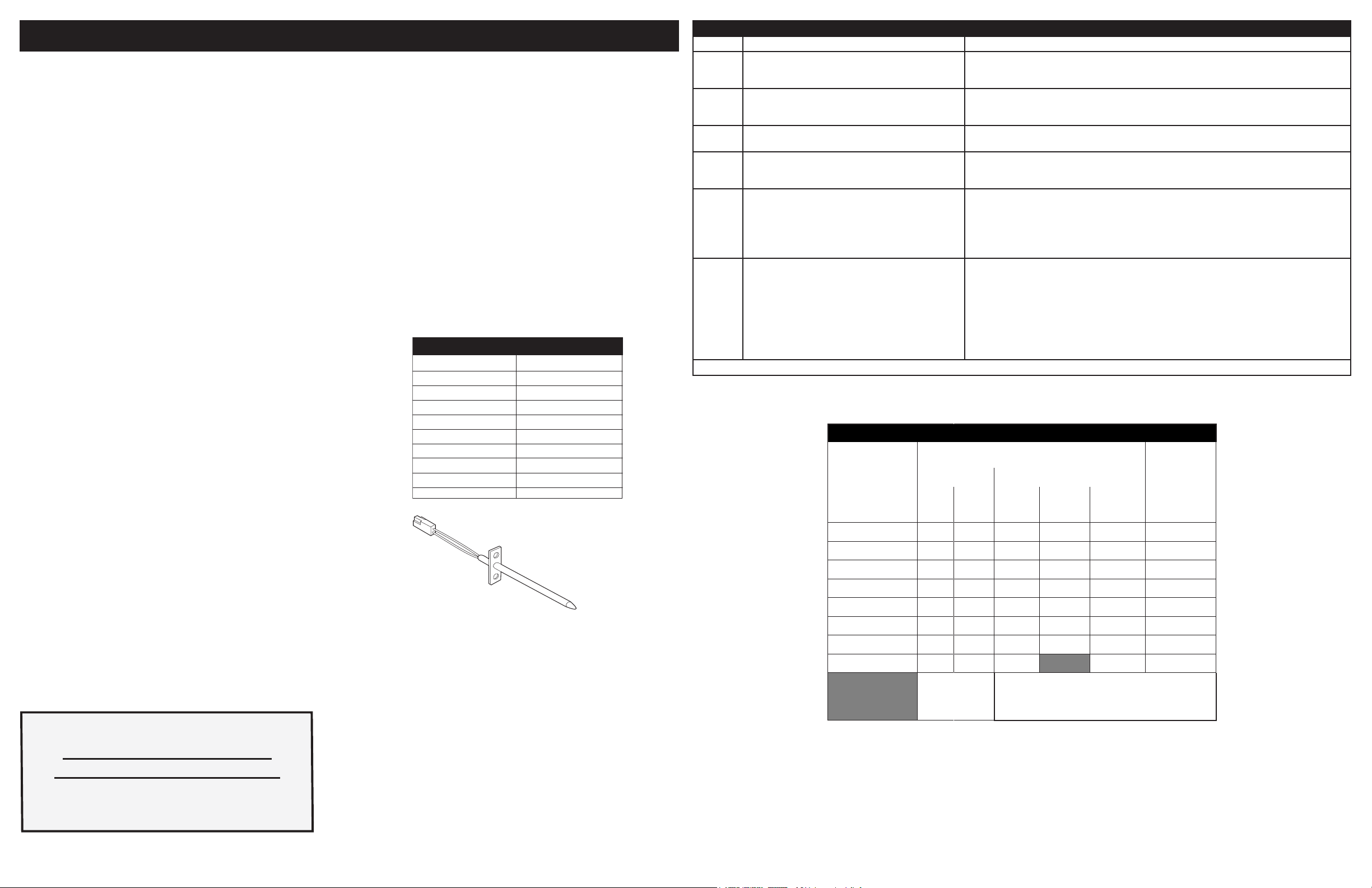
Resistance (ohms)
1000 ± 4.0
1091 ± 5.3
1453 ± 8.9
1654 ± 10.8
1852 ± 13.5
2047 ± 15.8
2237 ± 18.5
2697 ± 24.4
Open circuit/infinite resistance
RTD SCALE
Temperature °F (°C)
32 ± 1.9 (0 ± 1.0)
75 ± 2.5 (24 ± 1.3)
250 ± 4.4 (121 ± 2.4)
350 ± 5.4 (177 ± 3.0)
450 ± 6.9 (232 ± 3.8)
550 ± 8.2 (288 ± 4.5)
650 ± 9.6 (343 ± 5.3)
900 ± 13.6 (482 ±7.5)
Probe circuit to case ground
Resistance Temperature Detector
SERVICE DATA SHEET
Appliance with 5xx Electronic Oven Control
NOTICE: This service data sheet is intended for use by persons having electrical
and mechanical training and a level of knowledge of these subjects generally
considered acceptable in the appliance repair trade. The manufacturer cannot
be responsible, nor assume any liability, for injury or damage of any kind arising
from the use of this data sheet.
SAFE SERVICING PRACTICES
To avoid the possibility of personal injury and/or property damage, it is important
that safe servicing practices be observed. The following are some, but not all,
examples of safe practices.
1. Do not attempt a product repair if you have any doubts as to your ability to
complete it in a safe and satisfactory manner.
2. Before servicing or moving an appliance, remove power cord from electric
outlet, trip circuit breaker to Off, or remove fuse.
3. Never interfere with the proper installation of any safety device.
4. Use only replacement parts specied for this appliance. Substitutions may
not comply with safety standards set for home appliances.
5. Grounding: The standard color coding for safety ground wires is green
or green with yellow stripes. Ground leads are not to be used as current
carrying conductors. It is extremely important that the service technician
reestablish all safety grounds prior to completion of service. Failure to do so
will create a potential hazard.
6. Prior to returning the product to service, ensure that:
• All electric connections are correct and secure.
• All electrical leads are properly dressed and secured away from sharp
edges, high-temperature components, and moving parts.
• All uninsulated electrical terminals, connectors, heaters, etc. are ade-
quately spaced away from all metal parts and panels.
• All safety grounds (both internal and external) are correctly and se-
curely reassembled.
• All panels are properly and securely reassembled.
OVEN CALIBRATION
Set the electronic oven control for normal baking at 350°F. Allow oven to preheat
to set temperature. Obtain an average oven temperature after a minimum of ve
cycles. Press the STOP key to end the Bake mode.
TEMPERATURE ADJUSTMENT
1. While in a non-cooking mode, press and hold the Bake key for 6 seconds.
2. The current calibration offset (temperature adjustment) should appear in the
temperature display.
3. Use the number keys (0-9) to enter the desired amount of adjustments (up
to 35°F).
4. Press the Self Clean key to change the sign of the adjustment to a (-), if
necessary. A positive adjustment will not display a sign.
5. Once the desired adjustment (-35° to 35° F) has been entered, press the
Start key to accept the change or the Cancel key to reject the change.
Note: Changing calibration affects all Baking modes. The adjustments made will
not change the self-cleaning temperature.
2-SPEED COOLING FAN
The EOC controls the speed of the cooling fan. The cooling fan is activated at
low speed during any cooking function and will remain on until the oven is cooled
down. The high speed is activated during the broil (with open door) and during
clean cycles only when the temperature is above apporximately 575°F/302°C.
ELECTRONIC OVEN CONTROL (EOC) FAULT CODE DESCRIPTIONS
Code Condition / Cause Suggested Corrective Action
F10 Control has sensed a potential runaway oven con-
F11 Shorted Key: A key has been detected as pressed
F13 Control’s internal checksum may be corrupted. • Press CLEAR key. - Disconnect power, wait 10 seconds, and reapply power. If fault
F14 Misconnected at cables. No communication be-
F30
or
F31
F90
F94
Note: Generally speaking, F1X implies a control failure, F3X an oven probe problem, and F9x a latch motor problem.
dition, control may have shorted relay, and/or RTD
sensor probe may have gone bad.
(for a long period). Will be considered a shorted key
alarm and will terminate all oven activity.
tween oven and controls.
Open RTD sensor probe/ wiring problem. Note: EOC
may initially display an “F10,” thinking a runaway
condition exists.
Shorted RTD sensor probe /wiring problem.
to
Door motor mechanism failure.
Check RTD sensor probe and replace, if necessary. If oven is overheating, disconnect power.
If oven continues to overheat when power is reapplied, replace the Electronic Oven Control
(EOC).
1. Press STOP key.
2. If the problem persists, replace the EOC.
returns upon power-up, replace EOC.
1. Disconnect power. Verify the at cable connection between the touch panel or membrane
and the EOC on P12 and P13.
2. If the problem persist, replace the EOC.
1. Check wiring in probe circuit for possible open or short condition.
2. Check RTD resistance at room temperature (compare to probe resistance chart). If resistance does not match the chart, replace the RTD sensor probe.
3. Let the oven cool down and restart the function.
4. If the problem persists, replace the EOC.
1. Turn off power for 10 seconds, then turn on power. Test the door latch again (try to start a
Clean cycle).
2. If it fails, check wiring of Lock Motor, Lock Switch and Door Switch circuits.
3. Unplug the lock motor from the board and apply power (L1) directly to the Lock Motor. If
the motor does not rotate, replace Lock Motor Assembly.
4. Check Lock Switch for proper operation (do the contacts open and close, check with ohm-
meter). The Lock Motor may be powered as in above step to open and close Lock Switch.
If the Lock Switch is defective, replace Motor Lock Assembly.
5. If all above steps fail to correct situation, replace the EOC.
p/n 807153904 Rev A (2017/06)
OVEN CIRCUIT ANALYSIS MATRIX
ON RELAY BOARD ON DISPLAY
ELEMENTS
BakeP9Broil
P7
Preheat X X X
Bake X X X
Broil X X
Clean X X X
Locking/Unlocking X
Light X
Door Open X
Door Closed X
=Relay will operate only in this
condition
Light
J3-8
NOTES: Bake, broil, and convection elements alternate cycles. Convection fans may run during preheat
and may run intermittently during non-convection
functions to improve cooking performance.
Door
Motor
J3-6
Cooling
Fan
BOARD
Door Switch
P11-2, P11-7
Page 2
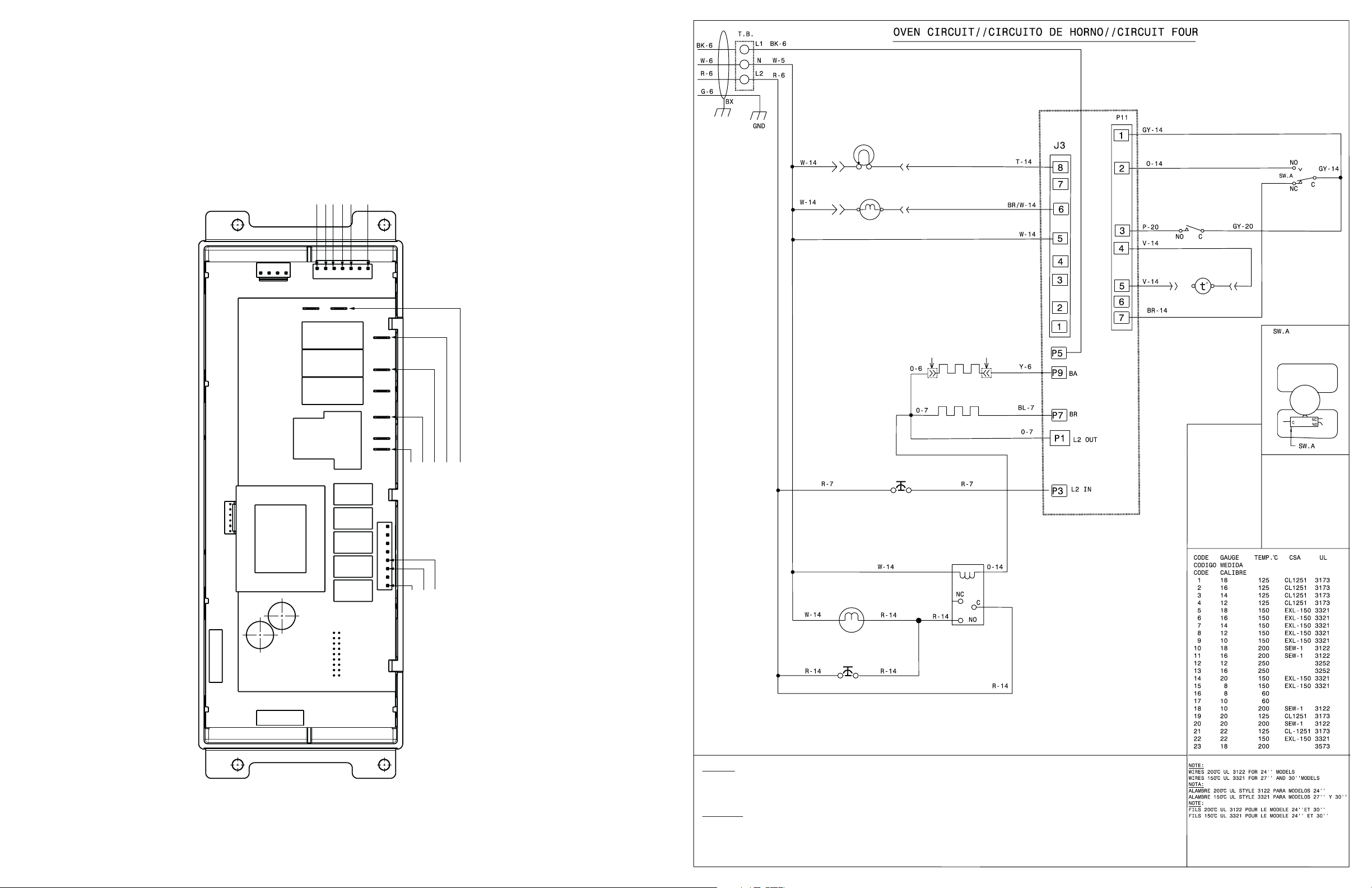
OVEN LAMP
MDL SWITCH, NORMALLY CLOSED
LAMPE DU FOUR
ELECTRONIC OVEN CONTROL
COMMANDE ÉLECTRONIQUE DU FOUR
P12
1
1
P2
MDL SWITCH, NORMALLY OPEN
DOOR SWITCH
COMMON
TEMP PROBE
TEMP PROBE
1
P11
P5
P15
P7
P9
P11
P1
P17
K1 K7 K5 K3
P3
L2 IN
J3
1
BAKE
BROIL
L2 OUT
L1 IN
LATCH MOTOR
MOTEUR VERROU
BAKE ELEMENT
ÉLÉMENT DE CUISSON
BROIL ELEMENT
ÉLÉMENT DE GRILLAGE
SAFETY THERMOSTAT
THERMOSTAT DE SÉCURITÉ
RELAIS DU VENTILATEUR DE REFROIDISSEMENT
COOLING FAN RELAY
DOOR SWITCH
INTERRUPTEUR DE PORTE
TEMPERATURE PROBE
SONDE À TEMPÉRATURE
INTER.DU LOQUET MOTORISÉ DE LA PORTE
COLOR CODE
CODE DE COULEURS
BK=BLACK/NOIR
BR=BROWN/BRUN
R =RED/ROUGE
O =ORANGE
Y =YELLOW/JAUNE
GN=GREEN/VERT
BL=BLUE/BLEU
PU=PURPLE/POURPRE
GY=GREY/GRIS
W =WHITE/BLANC
T =TAN/OCRE
PK=PINK/ROSE
C =C0PPER/CUIVRE
V =VIOLET
MOTOR DOOR LATCH SWITCH
K9 K11 K14 K16 K18
J3
1
NEUTRAL
OVEN LIGHT
COOLING FAN
VENTILATEUR DE REFROIDISSEMENT
FAN HOLD THERMOSTATE
THERMOSTAT DE VENTILATEUR
MOTOR DOOR LATCH MDL
CAUTION:
DISCONNECT POWER BEFORE SERVICING UNIT.
LABEL ALL WIRES PRIOR TO DISCONNECTION WHEN SERVICING CONTROLS.
WIRING ERRORS CAN CAUSE IMPROPER AND DANGEROUS OPERATION.
VERIFY PROPER OPERATION AFTER SERVICING.
ATTENTION:
DÉBRANCHEZ L'APPAREIL AVANT DE PROCÉDER À LA RÉPARATION.
IDENTIFIEZ TOUS LES FILS AVANT DE LES DÉBRANCHER LORSQUE VOUS PROCÉDEZ À UNE RÉPARATION.
UNE ERREUR DE FILAGE PEUT CAUSER UN FONCTIONNEMENT INADÉQUAT ET/OU UNE SITUATION DANGEREUSE.
VÉRIFIEZ QUE L'APPAREIL FONCTIONNE CORRECTEMENT APRÈS LA RÉPARATION.
Page 3

FEUILLET DE DONNÉES TECHNIQUES
DÉTECTEUR DE TEMPÉRATURE À RÉSISTANCE
Résistance (ohms)
1 000 ± 4,0
1 091 ± 5,3
1 453 ± 8,9
1 654 ± 10,8
1 852 ± 13,5
2 047 ± 15,8
2 237 ± 18,5
2 697 ± 24,4
Circuit ouvert/résistance infinie
ÉCHELLE DU DÉTECTEUR DE TEMPÉRATURE
À RÉSISTANCE
Température °F (°C)
32 ± 1,9 (0 ± 1,0)
75 ± 2,5 (24 ± 1,3)
250 ± 4,4 (121 ± 2,4)
350 ± 5,4 (177 ± 3,0)
450 ± 6,9 (232 ± 3,8)
550 ± 8,2 (288 ± 4,5)
650 ± 9,6 (343 ± 5,3)
900 ± 13,6 (482 ±7,5)
Circuit de la sonde mise à la
terre à la caisse
IMPORTANT
N’ENLEVEZ P
AS CE SAC OU NE
DÉTR
UISEZ P
AS SON CONTENU
CONTIENT LES SCHÉMAS DE CÂBLAGE ET
LES INFORMATIONS DE RÉPARATION
REMETTRE LE CONTENU
DANS LE SAC
Électroménager avec commande de four électronique 5XX
AVIS: Cette feuille de données d’entretien est destinée aux personnes ayant
reçu une formation en électricité et en mécanique, et qui possèdent un niveau
de connaissance jugé acceptable dans l’industrie de réparation des appareils
électroménagers. Le fabricant ne peut être tenu responsable, ni assumer aucune
responsabilité, pour toute blessure ou dommage de quelque nature que ce soit
pouvant résulter de l’utilisation de cette feuille de données.
NOTES IMPORTANTES: Cet appareil inclut un contrôleur de four électronique.
Le tableau de contrôle n’est pas réparable sur place.
PRATIQUES D’ENTRETIEN SÉCURITAIRES
Pour éviter tout risque de blessure et/ou dommage matériel, il est important que
des pratiques d’entretien sécuritaires soient suivies. Voici quelques exemples de
pratiques sécuritaires.
1. N’essayez jamais de réparer un appareil si vous ne croyez pas avoir les
compétences nécessaires pour le faire de manière satisfaisante et sécuritaire.
2. Avant de procéder au service d’entretien ou de déplacer tout appareil
ménager, débranchez le cordon d’alimentation de la prise électrique, réglez
le disjoncteur de circuit à OFF, ou enlevez le fusible et fermez le robinet
d’alimentation en gaz.
3. N’entravez jamais l’installation adéquate de tout dispositif de sécurité.
4. Utilisez que les pièces de remplacement énumérées dans le catalogue pour
cet appareil. La moindre substitution risque de ne pas être conforme aux
normes de sécurité établies pour les appareils électroménagers.
5. Mise à la Terre: La couleur de codage standard des conducteurs de mise à
la terre de sécurité est verte ou verte à barres jaunes. Les conducteurs de
mise à la terre ne doivent pas être utilisés comme conducteurs de courant.
Il est d’une importance capitale que le technicien d’entretien complète
toutes les mises à la terre de sécurité avant de terminer le service. Si cette
recommandation n’est pas suivie à la lettre, il en résultera des risques pour
les personnes et les biens.
6. Avant de retourner le produit au service de réparation ou d’entretien, assurez-vous que:
• Toutes les connexions électriques sont correctes et sécuritaires.
• Tous les conducteurs électriques sont correctement préparés et à l’abri
des bords tranchants, des composants à température élevée, et des
parties mobiles.
• Toutes les bornes électriques, connecteurs, réchauffeurs, etc. dénudés
sont espacés convenablement loin de toute pièce en métal et des
panneaux.
• Toutes les mises à la terre de sécurité (interne et externe) sont cor-
rectement ré-assemblées de façon sécuritaire.
• Tous les panneaux sont correctement et fermement remontés.
p/n 807153904 Rev A (2017/06)
ÉTALONNAGE DU FOUR
Réglez le régulateur électronique de four pour une cuisson normale à 350 ºF
(177 ºC). Comptez-vous de four préchauffer choisir températures. Vous devez
obtenir une température moyenne de four après 5 cycles. Appuyez sur la touche
Stop (arrêt) pour mettre n au mode de cuisson.
RÉGLAGE DE LA TEMPÉRATURE
1. Assurez-vous de ne sélectionner aucun mode de cuisson, puis appuyez
sur la touche Bake (cuisson au four) et maintenez-la enfoncée pendant 6
secondes.
2. L’afcheur de température indique l’écart actuel de calibration (ajustement
de température).
3. Utilisez les touches numériques (0 à 9) pour entrer l’ajustement désiré
(jusqu’à 35 ºF/19 ºC).
4. Appuyez sur la touche Self Clean (autonettoyage) pour ajouter le symbole
à (-) à l’ajustement, si nécessaire. Aucun signe n’apparaît si l’ajustement est
positif.
5. Lorsque vous avez fait le réglage désiré (-35 à 35 ºF / -18 à 18 ºC), appuyez
sur la touche Start (mise en marche) pour conrmer le choix ou Cancel
(annuler)
6. pour l’annuler.
Remarque: La modication de la calibration affecte tous les modes de cuisson.
Les ajustements n’inuent pas sur la température du cycle d’autonettoyage.
2-VITESSE VENTILATEUR RAFRAÎCHISSANT
Les contrôleurs de four électronique dirige vitesse de le ventilateur rafraîchissant.
Le ventilateur rafraîchissant activer à basse vitesse vitesse pendant une cuisson
fonction, et il reste allumé jusqu’à ce que du four refroidir. Le haut débit activer
pendant grillage (avec la porte ouverte) et pendant clean cycles seul quand la
température est plus que approximativement 575ºF/302ºC.
DESCRIPTION DES CODES D’ERREUR
Code Condition / Cause Action corrective suggérée
F10 La commande a décelée une condition possible
F11 Touche en court-circuit: Si la commande détecte
F13 La mémoire interne de la commande est corrompue. • Appuyez sur ANNULER. Coupez le courant, attendez 10 secondes, et rétablissez le
F14 Câbles plats mal branchés. No communication pas
F30
ou
F31
F90
F94
Note: Généralement F1X signie un problème avec le contrôleur, F3X un problème avec la sonde, et F9X un problème avec le moteur verrou de la porte.
d’emballement, la commande présente un relais en
court-circuit, et (RTD) mauvais fonctionnement de la
sonde.
qu’une touche est appuyée pendant une longue période de temps. Elle sera considérée en court-circuit.
La commande génère un signale sonore et éteint le
four.
entre le four et les contrôleurs.
Problème avec le lage de sonde ou lage ouvert.
Note: EOC afche initialement le code “F10”, signi-
ant qu’il décèle une condition d’emballement.
Court circuit de la sonde/problème de lage.
à
Système de verrouillage de porte défectueux.
Vériez la sonde RTD et remplacez-la, si nécessaire. Si le four surchauffe, débranchez-le. Si le
four continue de surchauffer, remplacez le contrôleur de four électronique.
1. Appuyez sur ANNULER.
2. Si le problème persiste, remplacez le EOC.
courant. Si l’erreur réapparaît, remplacez le EOC.
1. Coupez le courant électrique. Vériez la connexion du câble plat entre le panneau des
touches et le panneau EOC à la tige P12 et P13.
2. Si le problème persiste, remplacez le EOC.
1. Vériez si le lage de la sonde qu’il n’est pas en court-circuit.
2. Vériez la résistance RTD à la température de la pièce (comparez la valeur avec le tab-
leau). Si celle-ci ne concorde pas avec le tableau, remplacez le senseur de la sonde RTD.
3. Laissez refroidir le four et redémarrez la fonction.
4. Si le problème persiste, remplacez le EOC.
1. Coupez le courant électrique pendant 10 secondes et réappliquez le courant par la suite.
2. Vériez le lage du moteur verrou, de l’interrupteur et le circuit de l’interrupteur de la
porte.
3. Débranchez le moteur du EOC et branchez (L1) directement au moteur. Si le moteur ne
tourne pas, remplacez l’assemblage du moteur.
4. Vériez si les interrupteurs fonctionnent correctement. (Est-ce qu’il permet de fermer et
d’ouvrir la porte? Vériez avec un ohm mètre). Le moteur verrou doit être réactivé tel
qu’indiqué à l’étape précédente an que l’interrupteur s’ouvre et se ferme. Si l’interrupteur
verrou est défectueux, remplacez-le.
5. Si toutes les étapes mentionnées ci-haut ont échouées, remplacez le EOC.
TABLEAU D’ANALYSE DU CIRCUIT
À BORD DU RELAIS ON DISPLAY
ELEMENTS
Cuire P9Griller
P7
Préchauffage X X X
Cuire X X X
Gril X X
Nettoyer X X X
Verrouil./deverrouil. X
Lampe X
Porte ouverte X
Porte fermée X
=Relay will operate only in this
condition
Lampe
J3-8
NOTES: Bake, broil, and convection elements alternate cycles.
Convection fans may run during preheat and may run intermittently during non-convection functions to improve cooking
performance.
Moteur verrou
de la porte
J3-6
Ventilateur de
refroidissement
BOARD
Interrupteur de
porte
P11-2, P11-7
Page 4

L1 ENTRÉE
INTER. DU MDL, NORMALEMENT OUVERT
COMMUNE
1
1
P12
P11
P15
INTERRUPTEUR DE PORTE
SONDE À TEMPÉRATURE
SONDE À TEMPÉRATURE
INTER. DU MDL, NORMALEMENT FERMÉ
P5
P7
OVEN LAMP
LAMPE DU FOUR
LATCH MOTOR
MOTEUR VERROU
BAKE ELEMENT
ÉLÉMENT DE CUISSON
ELECTRONIC OVEN CONTROL
COMMANDE ÉLECTRONIQUE DU FOUR
DOOR SWITCH
INTERRUPTEUR DE PORTE
TEMPERATURE PROBE
SONDE À TEMPÉRATURE
MOTOR DOOR LATCH SWITCH
INTER.DU LOQUET MOTORISÉ DE LA PORTE
P9
BROIL ELEMENT
ÉLÉMENT DE GRILLAGE
P11
COLOR CODE
CODE DE COULEURS
P1
P17
K1 K7 K5 K3
P3
SAFETY THERMOSTAT
THERMOSTAT DE SÉCURITÉ
GRIL
CUISSON
L2 ENTRÉE
J3
1
1
L2 SORTIE
P2
K9 K11 K14 K16 K18
J3
1
NEUTRE
RELAIS DU VENTILATEUR DE REFROIDISSEMENT
COOLING FAN
VENTILATEUR DE REFROIDISSEMENT
FAN HOLD THERMOSTATE
THERMOSTAT DE VENTILATEUR
COOLING FAN RELAY
BK=BLACK/NOIR
BR=BROWN/BRUN
R =RED/ROUGE
O =ORANGE
Y =YELLOW/JAUNE
GN=GREEN/VERT
BL=BLUE/BLEU
PU=PURPLE/POURPRE
GY=GREY/GRIS
W =WHITE/BLANC
T =TAN/OCRE
PK=PINK/ROSE
C =C0PPER/CUIVRE
V =VIOLET
LAMPE DU FOUR
MOTEUR VERROU DE LA PORTE (MDL)
CAUTION:
DISCONNECT POWER BEFORE SERVICING UNIT.
LABEL ALL WIRES PRIOR TO DISCONNECTION WHEN SERVICING CONTROLS.
WIRING ERRORS CAN CAUSE IMPROPER AND DANGEROUS OPERATION.
VERIFY PROPER OPERATION AFTER SERVICING.
ATTENTION:
DÉBRANCHEZ L'APPAREIL AVANT DE PROCÉDER À LA RÉPARATION.
IDENTIFIEZ TOUS LES FILS AVANT DE LES DÉBRANCHER LORSQUE VOUS PROCÉDEZ À UNE RÉPARATION.
UNE ERREUR DE FILAGE PEUT CAUSER UN FONCTIONNEMENT INADÉQUAT ET/OU UNE SITUATION DANGEREUSE.
VÉRIFIEZ QUE L'APPAREIL FONCTIONNE CORRECTEMENT APRÈS LA RÉPARATION.
 Loading...