

Page 1
_NSTALLAT_ON AND SERVICE MUST BE PERFORMED BY A QUAUF_ED _NSTALLER.
_MPORTANT: SAVE FOR LOCAL ELECTRICAL _NSPECTOR'S USE.
READ AND SAVE THESE _NSTRUCT_ONS FOR FUTURE REFERENCE.
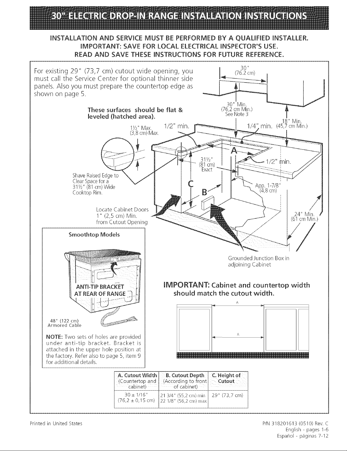
For existing 29" (73,7 cm) cutout wide opening, you
must calI the Service Center for optional thinner side
panels. Also you must prepare the countertop edge as
shown on page 5.
These surfaces should be flat &
leveled (hatched area).
1V2"Max. I/2" rain.
(3,8cm) Max,
ShaveRaisedEdgeto
ClearSpacefor a
31V2"(81cm)Wide
Cooktop Rim.
Locate Cabinet Doors
1" (2,5 cm) Min.
from Cutout Opening
30 "
(76.2cm)
30" Min.
(76,2cm Min.)
SeeNote3
18" Min.
rain. (45,7cm Min.)
(61 cmMin.)
Smoothtop Models
48" (122 cm)
Armored CaMe
NOTE: Two sets of holes are provided
under anti-tip bracket. Bracket is
attached in the upper hole position at
the factory. Refer also to page 5, item 9
for additional details.
A, Cuteut Width BoCutout Depth C Height Of
(Ceuntertop and !According to front
Cabinet) ' of cabinet)
30±1116" 21 3/4" (55,2 crn) rain 29" (73,7 cm)
(76,2±0,15cm) 22 1/8" (56,2 cm) max
I
Grounded Junction Box in
adjoining Cabinet
iMPORTANT: Cabinet and countertop width
should match the cutout width.
A
A
Printed in United States P/N318201613 (0510) Rev C
English - pages I-6
Espaflol - p_iginas 7-12
Page 2
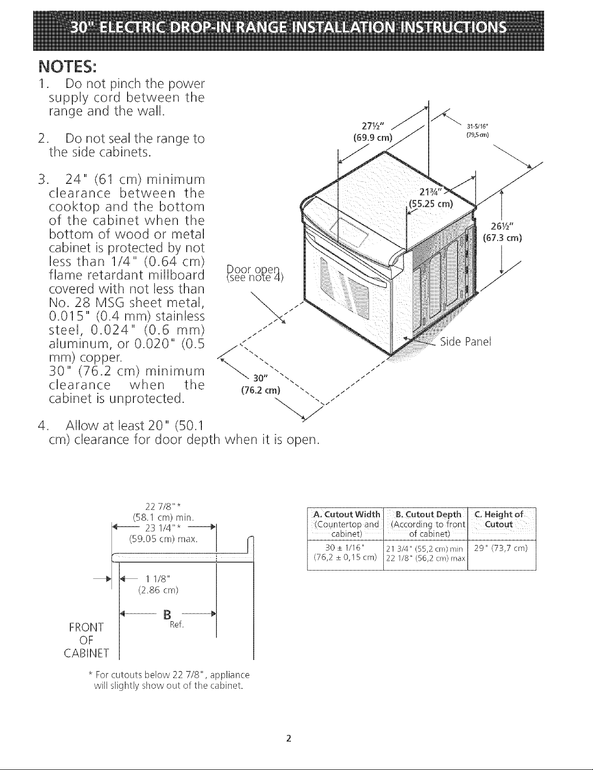
1. Do not pinch the power
supply cord between the
range and the wail.
Do not seal the range to
the side cabinets.
3. 24" (61 cm)minimum
clearance between the
cooktop and the bottom
of the cabinet when the
bottom of wood or metal
cabinet is protected by not
iess than 1/4" (0.64 cm)
flame retardant miliboard
covered with not less than
No. 28 MSG sheet metal,
0.015" (0.4 mm) stainiess
steei, 0.024" (0.6 mm)
aluminum, or 0.020" (0.5
ram) copper.
30" (76.2 cm) minimum
clearance when the
cabinet is unprotected.
Panel
4. Allow at least 20" (50.1
cm) clearance for door depth when it is open.
22 7/8" *
(58.1 cm) rain.
2S 1/4"*
(59.05 cm) max. r_
(2.86 OtTO
Ref,
OF
* For cutouts below 22 7/8", appliance
will slightly show out of the cabinet.
A. Cutout Width B.Cutout Depth C. Height of
(C0untertop and (According to front Cutout
Cabinet) ' of Cabinet)
30 ± I/16" 21 3/4" (55,2 cm) rain 29" (73,7 cm)
(76,2 ± 0,15 cm) 22 1/8" (56,2 cm) max
Page 3
Important Notes to the Installer
1. Readallinstructionscontainedintheseinstallation
instructionsbeforeinstallingrange.
2. Removeallpackingmaterialfromtheovenbefore
connectingtheelectricalsupplyto therange,
3. Observeallgoverningcodesandordinances,
4. Besuretoleavetheseinstructionswiththeconsumer.
5. Ovendoormayberemovedtofacilitateinstallation.
6. Donotlifttherangebythedoorhandle.
ImportantNotetothe Consumer
Keeptheseinstructionswithyourowner'sguideforfuture
reference.
• Before installing the range in an area covered
with linoleum or any other synthetic floor
covering, make sure the floor covering can
withstand heat at least 90°F above room
temperature without shrinking, warping or
discoJoring. Do not install the range over carpeting
unless you place an insulating pad or sheet of I/4"
thick plywood between the range and carpeting.
Never leave children alone or
unattended in the area where an appliance is in use.
As children grow, teach them the proper, safe use of all
appliances. Never leave tile oven door open when the
range is unattended.
RTANT SAFETY
INSTRU S
• Be sure your range is installed and grounded
properly by a qualified installer or service
technician.
This range must be electrically grounded in
accordance with local codes or, in their absence,
with the National Electrical Code ANSI/NFPA No.
7B--latest edition.
The installation of appliances designed for
manufactured (mobile) home installation must conform
with Manufactured Home Construction and Safety
Standard, title 24CFR, part 3280 [Formerly the Federal
Standard for Mobile Home Construction and Safety,
title 24, HUD (part 280)] or when such standard is not
applicable, the Standard for Manufactured Home
Installation 1982 (Manufactured Home Sites,
Communities and Setups), ANSI Z225.1/NFPA 501A-
latest edition, or with local codes.
• Make sure the wall coverings around the range
can withstand the heat generated by the range.
All ranges can tip
Injury to personscould result
Install anti4ip device packed with range
To reduce the risk of
tipping of the range, the range must be
secured by properly, installed anti-tip screws,
for models with coil elements They are
located in a plastic bag in the oven, For smoothtop models,
the anti-tip bracket located at the rear of the range fits under
the countertop and prevents range from tipping Failure to
install the anti-tip screws will allow the range to tip over if
excessive weight is placed on an open door or if a child climbs
upon it Serious injury, might result from spilled hot liquids or
from the range itself,
Stepping, leaning or sitting on the
door of this range can result in serious injuries and
can atso cause damage to the range.
Do not store items of interest to children in the
cabinets above the range. Children could be seriously
burned climbing on the range to reach items.
To eliminate the risk of burns or fire by reaching
over heated surface units,cabinet storage space
above the surface unit should be avoided. If
cabinet storage isto be provided the risk can be
reduce by installing a range hood that project
horizontally a minimum of 5 inches beyond the bottom
of the cabinet.
• Do not use the oven as a storage space. This
creates a potentially hazardous situation.
• Never use your range for warming or heating the
room. Prolonged use of tile range without adequate
ventilation can be dangerous.
• Do not store or use gasoline or other flammable
vapors and tiquids near this or any other
appliance. Explosions or fires could result.
Reset all controls to the "off" position after using
a programmable timing operation.
FOR MODELS WITH SELF-CLEAN FEATURE:
Remove broiler pan, food and other utensils
before self-cleaning the oven. Wipe up excess
spillage. Follow the precleaning instructions in the Use
and Care Guide.
Page 4
Electrical Requirements
This appliance must be supplied with the proper voltage
and frequency, and connected to an individual, properly
grounded branch circuit, protected by a circuit breaker or
fuse, having amperage as noted on the rating plate (the
rating plate is located on the oven frame).
If local codes permit, you (:an use a 3-wire single phase
120/208 or 120/240 Volt, 60Hz AC only electrical
system. If you connect to aluminum wiring, properly
installed connectors approved for use with aluminum
wiring must be use.
NOTE: Wire sizes and connections must conform with
the fuse size and rating of tile appliance in accordance
with the National Electrical Code ANSI/NFPA No. 70-
latest edition, and local codes and ordinances.
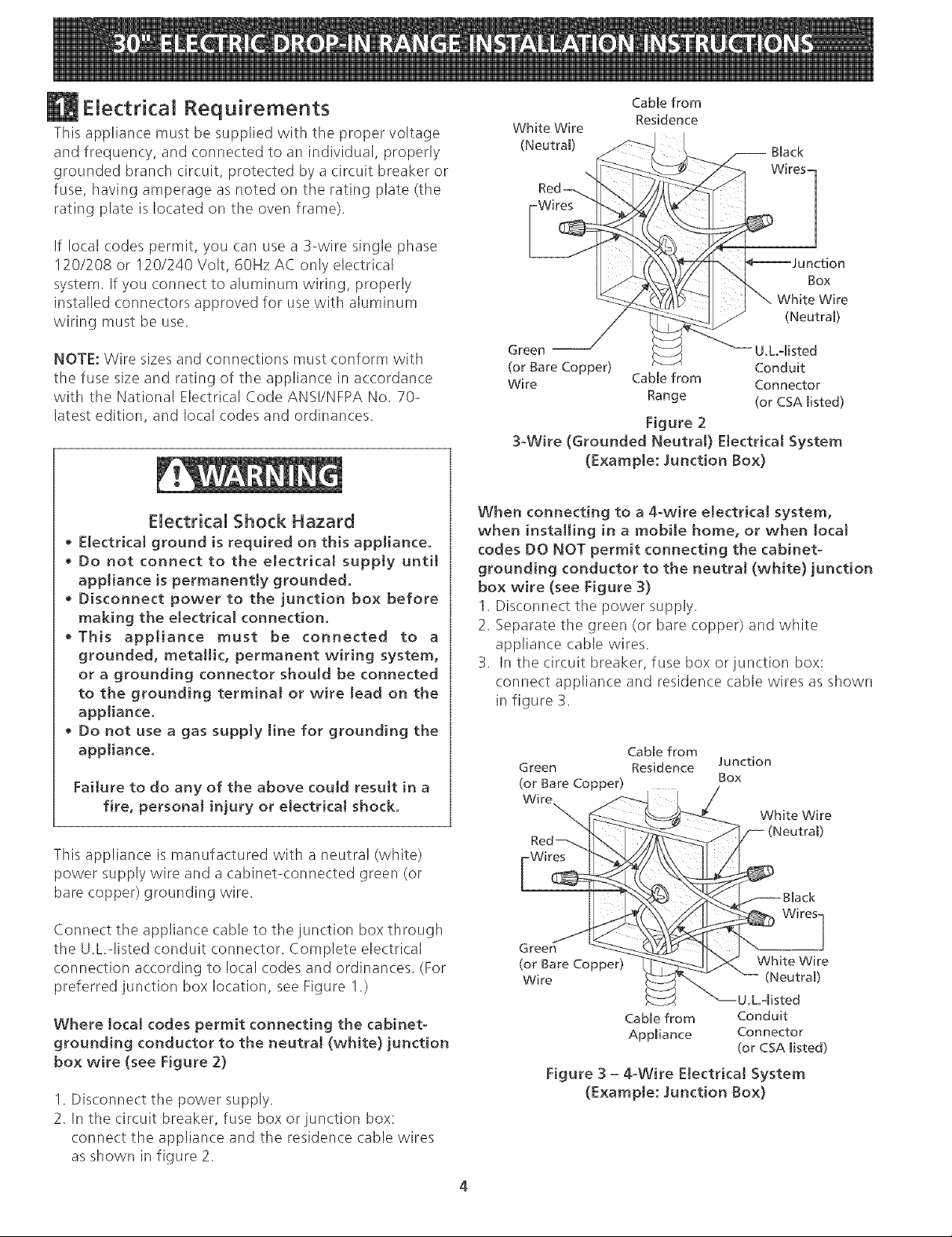
Cable from
White WEre
(Neutral)
Residence
Black
Wires]
Box
(Neutral)
Green -- U,L-listed
(or Bare Copper) Conduit
Wire Cable from Connector
Range (or CSA listed)
Figure 2
3-Wire (Grounded Neutral} Electrical System
(Example: Junction Box)
)n
Wire
Electrical Shock Hazard
• E[ectrkal ground is required on this appliance,
• Do not connect to the electrical supply until
appliance is permanently grounded.
• Disconnect power to the junction box before
making the etectrka[ connection.
• This appliance must be connected to a
grounded, metallic, permanent wiring system,
or a grounding connector should be connected
to the grounding terminal or wire lead on the
appliance.
• Do not use a gas supply line for grounding the
appliance.
Failure to do any of the above could result in a
fire, personal injury or electrical shock.
This appliance is manufactured with a neutral (white)
power supply wire and a cabinet-connected green (or
bare copper) grounding wire.
Connect the appliance cable to the junction box through
the U.L.qisted conduit connector. Complete electrical
connection according to local codes and ordinances. (For
preferred junction box location, see Figure 1.)
Where local codes permit connecting the cabinet-
grounding conductor to the neutral (white) junction
box wire (see Figure 2)
1. Disconnect tile power supply.
2. In the circuit breaker, fuse box or junction box:
connect the appliance and the residence cable wires
as shown in figure 2.
When connecting to a 4-wire electrical system,
when installing in a mobile home, or when local
codes DO NOT permit connecting the cabinet-
grounding conductor to the neutral (white) junction
box wire (see Figure 3)
1. Disconnect the power supply.
2. Separate tile green (or bare copper) and white
appliance cable wires.
3. In the circuit breaker, fuse box or junction box:
connect appliance and residence cable wires as shown
in figure 3.
Green Residence Junction
(or Bare Copper) Box
Wm
Green
(or Bare Copper)
Wire
Cable from
Cable from
Appliance
White Wire
White Wire
(Neutral)
U.L.qisted
Conduit
Connector
(or CSA listed)
Figure 3 - 4-Wire Electrical System
(Example: Junction Box)
Page 5
improper connection of aluminum
house wiring to copper Jeads can result in a short
circuit or fire. Use only connectors designed for
joining copper to aluminum, and fo!low the
manufacturer's recommended procedure closely.
NOTE TO ELECTRICIAN: The armored cable leads
supplied with this appliance are UL-recognized for
connection to larger gauge household wiring. The
insulation of the leads is rated at temperatures much
higher than the temperature rating of household wiring.
The current carrying capacity of the conductor is
governed by the temperature rating of tile insulation
around the wire, rather than the wire gauge alone.
Range JnstaINation
The eJectricat power to the range
must be shut off whiJe Hne connections are being
made. Failure to do so could result in serious injury
or death.
Countertop Preparation
The cooktop sides of the range fit over the cutout edge
of your (ountertop.
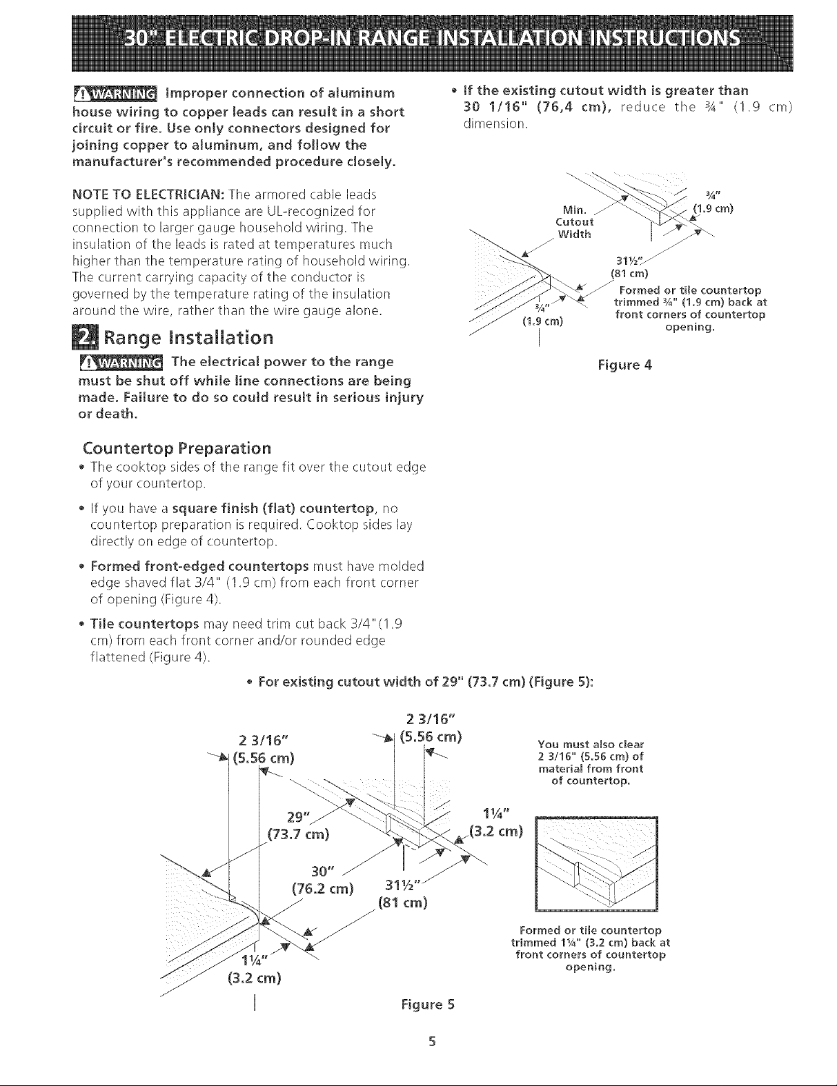
• If the existing cutout width is greater than
30 1/!6" (76,4 cm), reduce the 3A" (1.9 cm)
dimension.
(1.9cm)
/
/
311/£_
(81cm)
Formed or tile countertop
trimmed ¾" (1.9 cm) back at
(1.9 cm)
front corners of countertop
opening.
I
Figure 4
If you have a square finish (fiat} countertop, no
countertop preparation is required. Cooktop sides lay
directly on edge of countertop.
• Formed front-edged countertops must have molded
edge shaved flat 3/4" (1.9 cm) from each front corner
of opening (Figure 4).
• THe countertops may need trim cut back 3/4"(! .9
cm) from each front corner and/or rounded edge
flattened (Figure 4).
• For existing cutout width of 29" (73.7 cm) (Figure 5):
You must also dear
2 3/16" (5.56 cm) of
material from front
of countertop.
(S.2 cm)
Formed or the countertop
trimmed 11/4" (3.2 cm) back at
front corners of countertop
opening.
Figure 5
Page 6

This range is designed to hang from the countertop. It
does not rest on the floor.
Be sure the bottom of any wall cabinets are a minimum
of 30" (76.2 cm) above the rangetop area.
To eliminate the hazard or reaching over heated
surface units, cabinet storage space located above the
surface units should be avoided. If cabinet storage is to
be provided, the hazard can be reduced by installing a
range hood that projects horizontally a minimum of 5"
(12.7 cm) beyond the bottom front edge of the
cabinets.
Important Note: Door removal is not a requirement for
installation of the range, but is an added convenience.
Refer to the Use and Care Guide for oven door removal
instructions.
1. Install base cabinets 30" (76.2 cm) apart, and be
sure they are plumb and level before attaching to
countertop.
2. Cut countertop exactly as shown in Figure I. Shave
raised edge level to clear 31 I/2" (81 cm) wide rim
on rolled edge styled countertops.
3. Install the wiring junction box in an adjoining
cabinet or under the floor (range has 48"/122 cm of
conduit). Cut 1-I/4" (3.2 cm) hole to bring conduit
to the junction box.
4. To provide an optimum installation, tile top surface
of the countertop must be level and flat (lie on the
same plane) around the 3 sides that are adjacent to
range cooktop. Proper adjustments to make the top
flat should be made or gaps between the
countertop may occur.
5. _ To reduce the risk of damaging your
appliance, do not handle or manipulate it by the
ceramic: glass. Manipulate with care.
6. Move range in front of cabinet opening.
7. Push the electric conduit through the hole and
attach it to the junction box. Leave enough slack in
the conduit to allow the range to be pulled forward
several inches for service if necessary.
8. Oven door is heavy. It is advisable to remove
door and eliminate its weight as range is tifted
into position. See oven door removal
instructions in the Use and Care Guide. Lift the
range into position on the countertop and
make sure the appliance is centered in the
cutout opening to be sure that the flanges of
the upper side paneJ are sitting on the
countertop to avoid gJass breakage.
Ranges with Ceramic Ghss Cooktop
9. This range is equipped with an anti-tip bracket
attached to the back of tile range with two screws.
If countertop thickness is greater than I/2" (1.3 cm),
relocate anti-tip bracket to tile lower position 1/4"
(6.4 ram) below (see Figure 1, page 1).
10. Anti-slide brackets Installtion (Figure 6):
1. Placethe range so that it is about 6" ou of the
cabinet.
2. Insert from below the shoulder screws in the side
panel (one on each side)
3. Slide the range into its final position.
4. Position the "L" bracket against the side of tile
cabinet so that it is retained by the shoulder
screws, hold bracket and mark the holes on the
inside of tile cabinet. Drill pilot holes into cabinet
where you just marked (Caution should be take to
avoid drilling throught the opposite side of the
cabinet). Attach the "L" bracket to the cabinet
with the screws provided (don't forget to insert
the shoulder screw into tile bracket).
5. Repeat steps 4 on the other side.
11. Install the decorative lower trim under tile door using
tile screws provided with tile range.
Figure 6
Ranges with a lift-up cooktop:
9. Anti-tip/anti-slide screws installation:
1. Slide the range to its final postion.
2. Lift the cooktop and secure range burner box to
cabinet with screws supplied to prevent range
from tipping (Figure 7).
10. Install tile decorative lower trim under the door using
tile screws provided with the range.
Page 7

Anti-Tip
mountingscrews
2oneach
Figure7
Broil-When the oven isset to BROIL, the upper element
in tile oven should become red.
Clean (some models)-When the oven is set for a self-
cleaning cycle, the upper element should become red
during the preheat portion of tile cycle. After reaching
the self-cleaning temperature, the lower element will
become red.
Convection (some models)-When the oven isset for
convection baking or roasting, both elements cycle on
and off alternately and the convection fan will turn. The
convection fan will stop turning when the oven door is
opened during convection baking or roasting.
IMPORTANT NOTE: A fan inside the upper rear part
above tile oven (some models) provides additional
cooling of the oven electrical and electronic components.
Tile fan will continue to run after tile oven has been
operating at high temperatures.
Model and Serial Number Location
The serial plate is located along the side of the oven
door in tile open position.
Checking Operation
Some models have manual controls. Refer to the
Owner's Guide and check all controls for correct
operation.
Some models are equipped with an electronic oven
control, Each of the functions has been factory checked
before shipping, However, it is suggested that you verify
the operation of the electronic oven controls once more,
Refer to tile Owner's Guide for operation, Follow the
instructions for tile Clock, Timer, Bake, Broil, Convection
(some models) and Clean (some models) functions,
Bake-After setting the oven to 350% (I 77°C) for baking,
the lower element in the oven should becorae red.
When ordering parts for or making inquires about your
oven, always be sure to include the model and serial
numbers and a lot number or letter from the serial plate
on your oven.
Before You Call for Service
Read tile Avoid Service Checklist and operating
instructions in your Owner's Guide. It may save you time
and expense. The list includes common occurrences that
are not the result of defective workmanship or materials
in this appliance.
Refer to the warranty in your Owner's Guide for our toll-
free service number and address. Please (:all or write if
you have inquiries about your product and/or need to
order parts.
Page 8

LA [NSTALACION Y EL SERV[aO DEBEN SER EFECTUADOS POR UN [NSTALADOR CAL[F[CADO.
[MPORTANTE: GUARDE ESTAS [NSTRUCCIONES PARA USO DEL
INSPECTOR LOCAL DE ELECTRIC[DAD.
LEA Y GUARDE ESTAS [NSTRUCC[ONES PARA REFERENC[A FUTURA.
VOTA: Para 29" (73,7 cm) anchura de la abertura,
_sted debe Ilamar al Centro de Servicios para los panties
aterales opcionales y borde ancho daro del cooktop (yea
p_flgina 10).
Lije la parte
elevade del
lY2" Max. 1/2" min.
(3,8 cm) Max.
borde para
obtener las
31Y2" (81 cm)
de ancho del
reborde de la
plar}cha de
COclnar.
30" (76.2 cm),
(76,2crnMin ) A
YeaNote3 j ......
18 Min.
min. (45,7 cm Min.)
Ubique las puertas de
los armarios un mfnimo
de 1" de la abertura.
Modelos de superfide Hsa
SOPORTEAN33VUELCO
AL FONDO DE LA ESTU[
Cable Blindado
NOTA: Hay dos juegos de aguieros
debajo del soporte antivuelco. Elsoporte
viene colo(ado, desde la f_brica, en el
agujero superior. Refierase para paginar
1I, el art[culo 9 para detalles adicionales.
24" M[n.
(61cm Min_)
La caja de empalmes de
conexi6n con la tierra.
[MPORTANTE: El ancho de [a cubierta
y el armario debe de ser igual al
ancho dei corte.
A
A
A. Anchura B. Profundidad ¢, A[tura de!
de ' de recortado armari Q
recortado (seg0eparte
(encima y armano) de[anterade[armario)
30± 1/16" 21 3/4" (55.2 cm) rain 29" (737 cm)
(762±015cm) 22 1/8" (56.2 cm) max
Imprimido en los Estados Unidos
P/N318201613 (0B10) Rew C
English - pages 1o7
Espafiol - p_iginas 8-14
Page 9

NOTAS:
1. No petlizque el cord6n el_ctrico entre
la estufa y la pared.
2. No 8elle la estufa a Io8 armarios de
lado.
3. Un espacio minimo de 24" (61 cm)
entre Ia superficie de Ia estufa y el
fondo deI armario cuando el fondo
det armario de madera o metal est,1
protegido pot no menos de 1/4" (0.64
cm) de madera resistente aI fuego
cubierta pot una lamina met_ilica de
MSG, nOmero 28, 0.015" (0.4 mm)
de acero inoxidabte, 0.024" (0.6 mm)
de aluminio, 6 0.02" (0.5 mm) de
cobre.
Un espacio minimo de 30" (762 cm)
cuando el armario no est,1 protegido.
4. Deje pot los 20" (50.1 cm) de espacio
libre para Ia profundidad de la puerta
cuando esta abierta=
Panel lateral
22 7/8" *
(581 cm) rain.
23 1/4" *
Z i
5905 cm) maxr----_
_-- lu8"
(2,86 cm)
PARTE B Ref_-_
DEL
ARMARUO
* Para los recortados menos que 22 7/8", el electrodomestico
aparecerfa ligeramente en el exterior del armario.
i B, Profundidad j C, Altura del
recortado
(encima y arrnario] delanteradelarmario)
30+- 1116" 21 3/4" (55.2 cm) rain 29" (737 cm)
(76_2_+0_15cm) 22 1/8" (56.2 cm) max
[ de recortado i armario
Page 10

Notas importantes para el instalador
1. Lea todas las instrucciones contenidas en este manual
antes de instalar la estufa.
2. Saque todo el material usado en el embalaje del
compartimiento del homo antes de conectar el
suministro electrico ala estufa.
3. Observe todos losc6digos y reglamentos pertinentes.
4. Deje estas instrucciones con el comprador.
5. Pare facilitar la instalacion puede quitarse la puerta
del horno.
6. No levante la estufa por la manila de la puerta.
Nota importante pare el consumidor
Conserve estas instrucciones y el Manual del Usuario para
referencia futura.
Manufactured Home Installation 1982 (Manufactured
Home sites, communities and setups) ; ANSIZ225.1/
NFPA 501A- Oltima edic.i6n o con c.6digos locales.
• Aseg(irese que el empapelado de pared alrededor
de ta cocina pueda resistir el cator generado pot
la cocina.
Antes de instalar ta cocina en una &rea cubierta
de [inoleo o cualquier otto revestidor de piso
sint_tico, asegQrese que _ste pueda resistir al
menos 90°F sobre Jatemperature de Japieza sin
encogerse, Jadearse o descoJorisarse. No instale la
cocina encima de una alfombra a menos qua coloque
una pla(.a de aislamineto o una plancha de 1/4" de
madera entre la cocina y el alfombrado.
IMPORTANTES
INSTRU DE
SEGURIDAD
• AsegQrese qua su codna est& instalada y
conectada adecuadamente a tierra pot un
instalador catificado o un t_cnico de servido.
• Esta codna debe set conectada a tierra
el6ctricamente de acuerdo con los c6digos
locales, o de no existir, con la National Electrical
Code ANS!/NFPA No.70- Qltima edici6n.
• La instalacion de el6ctrodom6sticos destinados para
c.asas(movibles) deben conformarse con la
Manufactured Home Construction and Safety
Standard, titulo 24CFR, parte 3280 [antiguamente la
Federal Standard for Mobile Home Construction and
Safety, titulo 24, HUD (parte 280)] o cuando este
c6digo no se aplica, la Standard for
Todas Jascocinas pueden indinarse_
Esto puede provocar lesiones personales,
Instale el dispositivo anti-indinaci6n qua
viene con lacocina
_!_ Pare reducir el riesgo de
qua se vuelque la estufa, hay qua asegurarla
adecuadamente coloc_indole los soportes
antivuelco qua se proporcionan, pare
modelos con elementos de bobina Las
piezas se encuentran en un saco de plastico en el horno_ Pare
rnodelos de tape lisa, el soporte antivueJco que se encuentra
al rondo de Ja estufa cabe debajo deJ tablero y evita que la
estufa se vueJque Si no se instaJan los torniJJos antivuelco, Ja
estufa podr_i volcarse si sele pone peso excesivo en la puerta
abierta o si un nitro se sube a 6lie. Esto puede resuJtar en
daBo serio si liquidos calientes se derrarnaran o si la estufa se
cayera_
Nunca deje a los nifos solos o sin
cuidado en el area donde el e!_ctrodom_stico at& en
uso. A medida qua los niflos crezcan, ensefleles el uso
adecuado de los electrodom6sticos.Nunca deje la puerta
del horno abierta cuando la cocina est6 sin supervision.
V!_ Pisar, apoyarse o sentarse entas
puertas o los calories de la codna pueden causer
graves herridas y tambi_n da_ar ta cocina.
• No coloque cosas qua atraigan a los niSos sobre
tos gabinetes encima de Jacocina. Los niflos
podr[an sufrir quemaduras tratando de alcanzarlos.
• Para evitar riesgos de quemaduras o incendios aJ
tocar superficies caHentes, se deben evitar los
armarios sobre ta superficie de los quemadores. Si
existe un armario, se pueden reducir los riesgos
instalando una campana qua se extienda
horizontalmente en un minimo de 5" por sobre la
parte inferior de los armarios.
No use et homo como espacio de
almacenamiento° Esto c.rea una situaciOn muy
peligrosa.
• Nunca use su cocina pare caJentar Ja pieza. El uso
prolongado de la cocina sin ventilaci6n adecuada
puede ser peligroso.
• No guarde o use gasoHna u otros vapores
inflamabtes y l_quidos cerca de _ste o cualquier
otto el_ctrodom_stico. Esto podria causer una
explosi6n o un incendio.
• Vuelva a programar todos los controJes a Ja
posici6n "off" (apagado) despu_s de haber
utitizado et conteo contador autom&tico.
PARA LOS MODELOS CON AUTO-LtMPIEZA:
Retire el rostisador, ta comida y otros utensitios
antes de auto-limpiar el homo. Limpie todo exceso
de derrames. Siga las instrucciones pare la pre-
limpieza en el Manual del usuario.
10
Page 11

Requisitos el ctricos
Este artefacto debe ser suministrado con el voltaje y la
frecuencia adecuados, y conectado a un circuito
individual correctamente puesto a tierra, protegido por
un (ortacircuitos o un fusible con el amperio anotado en
la plata de calificacion (la placa se encuentra en el
armaz6n del horno).
Si los codigos locales Io permiten, se puede usar un
sistema electrico de 3 alambres de fase 0nica de 120/
2086120/240voltios, 60HzACsolamente. Sise
conecta a un alambrado de aluminio, tienen que usarse
conectores bien instalados y aprobados para uso con el
alambrado de aluminio.
NOTA: Los tama{ios de alambres y conectores deben
conformarse con el tama{io del fusible y la calificacion
del artefacto de acuerdo con el Codigo Electrico
Nacional ANSI/NFPA No. 70-Oltima edici6n y los c6digos
y ordenanzas locales.
Riesgo de choque el_ctrico
o Una puesta a tierra se require en este aparato.
No Io conecte a la corriente etectrico hasta que
el aparato haya sido puesto a tierra.
, Desconecte [a corriente electrica a la caja de
empalmes antes de hacer [a conexibn el_ctrica.
, Este aparato debe estar conectado con un
sistema de alambres puesto en tierra, met_lico
y permanente o un conector de pueta a tierre
debe conectarse a[ terminal de puesta a tierra
o el alambre conductor en a[ aparato,
No utHice el suministro de gas para hacer [a
puesta a tierra.
Este aparato esta fabricado con un alambre electrico
neutro (blanco) y un alambre verde (o alambre pelado)
de puesta a tierra conectado al gabinete.
Conecte el cable del aparato a la caja de empalmes por
mediodelconductordeunionlistado-UL Completela
conexion seg0n los codigos y ordenanzas locales. (Rata
la ubicacicSn preferida de la caja de empalmes, v6ase la
Figura 1.)
Donde los cbdigos locales permitan ta conexi6n del
conductor de gabinete-puesta a tierra con el
a[ambre neutro (blanco) de [a caja de empa[mes
(yea figura 2)
1. Desconecte la fuente de alimentaciOn.
2. En el disyuntor, (aja de fusibles o la caja de
distribuci6n: conecte el artefacto y los cables de la
Cable de [a fuente
Alambre
B[anco
(Neutro)
Alambres_..
Alambres (Neutro)
desnudos Conductor de
o verdes Cable de ma (listadooCSA)
Figura 2 - Sistema e[_ctrico (ejemp[o: caja de
empa[mes} de 3 alambres (a t[erra neutral)
de abmentaci6n
-- Aiambres
negros[
Caja de
empalmes
Alambre
Blanco
uni6n mistadooUL
estufa
La falta de hacer cualquier de las cosas arriba
podria resultar en un incendio, choque et_ctrko
o [esiones personales.
residencia come se muestra en la figura 2,
Donde los c6digos locales NO permitan conectar el
conductor de puesta a tierra de[ e[_ctrodom_stico a[
neutral (blanco), o si est=i conectado con un sistema a
4 alambres (vea figura 3):
1. Desconecte el suministro el6ctrico
2. Separe el alambre verde (o cobre desnudo) y el
alambre blanco del electrodomestico.
3. En el disyuntor, caja de fusibles o la caja de
distribud6n: conecte el artefacto y los cables de la
residencia come semuestra en la figura 3.
11
Page 12

Una conexi6n incorrecta de!
a[ambrado de aluminio con los conductores de
cobre puede resu[tar en un cortadrcuito o incendioo
Use soiamente [os conectores dise_ados para juntar
el cobre con e[ aluminio y siga exactamente e[
procedirniento recornendado pot e[ fabricante.
NOTA AL ELECTRIC[STA: Los conductores de cable
blindados provistos con este artefacto son aprobados por
UL para la conexi6n al alambrado de casa de un calibre
Aiambre CabUe de [a fuente Caja de
desnudo o de a[imentaci6n empalmes
verde \ j_ L_--_--- / A,ambre
A[ambres I'_ _ _-_ ,_- glanco
/___Neutro)
desnudos o y__ AUambre
verdes _X _ "_ Bmanco
Cable de [a _-Conductor de
_ (Neutro)
estufa uni6n [istado_UL
(o listado-CSA)
Figura 3 ° Sistema e[6ctrico de 4 a[ambres
(ejemp[o caja de empa[me)
mayor, El aislamiento de los conductores esta calificado
para temperaturas m_s altas que las del alambrado de la
casa. La capacidad de corriente del conductor est_
gobernada pot la calificaci6n de la temperatura del
aislamiento alrededor del alambre en vez de solamente
el calibre del alambre.
2 3116"
3/16"
29"_ 1_,/4"
(73.7 cm) .(3.2 cm)
(76.2 cm) 311/2"/
_o_trador moIdeado o enazulejo recortad
_4" (1 9 cm) hada atr&s en las esquinas de frente
(81 cm) G 3/
de [a abertura del mostrador.
lnstalad6n de la estufa
La corriente el_ctrica a [a estufa debe
apagarse m[entras se hagan tas conexiones. S[ no se
hace esto puede provocar daho serio o muerte.
Preparaci6n del mostrador
Las extremidades de la cocina sobrepasan el borde de
SU mostrador.
• Sitiene un mostrador con [as extremidades
cuadradas (planas), no se necesita ninguna
preparaci6n del mostrador.
El reborde de frente de mostradores moldeados
deben tener bordes moldeados a 3/4" (1.9cm) a partir
de cada extremidad de la apertura (Figura 4).
Los mostradores enazulejos deber_n necesitar un
recorte de 3/4" (1.9 (m) a partit de (ada extremidad
y/o un borde redondeado aplanado (Figura 4).
Anchura
de hueco
mira
31y2'_ /
(81 cm)
Mostrador moldeado o
jo recortado 3/4" (1.9 cm)
(1.9cm)
I
hada atr_is en [as esquinas de
frente de [a abertura de[
Figura 4
• Si el ancho de ta abertura de[ mostrador es m&s
grande que 30 1/16" (76,4 cm), ajuste alas
dimensiones (omo para el 3/4" (1.9).
Para ta Anchura existente de[ Recorte de el
Quite el 2 3/16" de material de
frente a la parte posteriora.
(1.9cm)
mostrador.
29"(73.7 cm)
(Figura 5):
Esta estufa esta
diseflada para
colocarse en el
tablero. No se
sostiene en el piso.
AsegOrese de que la
parte baja de los
armarios este a una
altura de un mlnimo
de 30" (76.2 cm)
del _rea de la
estufa.
(3.2 cm)
Figura 5
12
Page 13

Paraeliminarelpeligrodetenerqueextenderelbrazopor
encimadelasuperficiecalientedelaestufa,sedebe
evitarlainstalaciondegabinetesporencimadeella.Si
hayqueinstalargabinetesporencimadelaestufa,se
puedereducirelriesgoinstalandounventiladordeestufa
queseproyectehorizontalmenteunminimode5" (12.7
cm)masaliadelhordedelanteroinferiordelosgabinetes.
Notaimportante:Noesnecesario,perosies
conveniente,quitarlapuertaparainstalarelhorno.
ConsultelasinstruccionespararetirarlapuertaenlaGuia
deUsoyCuidado. _f_/,4
1. Instalelosgabinetesinferi_ioresconunaseparacionde
30"(76.2cm),yasegOresedequeest6naplomoy
niveladosantesdeunirlosaltablero.
2. Corteeltableroexactamentecomosemuestraenla
FiguraI. Cepilleanivelelbordelevantado,para
paraquelibreunfiletede31I/2" (81cm)deancho
entablerosconhordeslaminados.
3. Instalelacajadeconexioneselectricasenunarmario
adjuntoodebajodelpiso(laestufatiene48"/I22cm
dealambre).Abraunagujerode1-1/4"(3.2cm)para
traerelalambrehastalacajadeconexiones.
4. Paraunainstalacionoptima,lasuperficiesuperiorde
lamesadadebeestarniveladayserplana(sobreel
mismopiano)enlos3ladosadyacentesalacocina.
Sedebenhacerlosajustescorrespondientespara
hacerquelapartesuperiorquedeplana,deIo
contrariopodranquedarespaciosentrelamesadayla
(.ocina.
5. F!_ Rata reducir el riesgo de da¢iar su
artefacto, no Io manipule cerca del vidrio ceramico.
ManipL_lelocon cuidado.
6. Coloque la cocina enfrente de la abertura del armario.
7. Introduzca el alambre electrico pot el agujero y fijelo a
la caja. Deje suficiente alambre flojo para permitir
que la estufa sejale hacia delante varias pulgadas si
fuera necesario darle servicio.
8. La puerta del horno es pesada. Se aconseja retirar
la puerta para eliminar su peso mientras se
coloca la cocina en posici6n. Ve a las
instrucciones para retirar la puerta del homo en
la Guia de Uso y Cuidado. Levante la cocina y
col6quela en posici6n sobre la mesada y
asegurese que el artefacto est& centrado en la
abertura de corte para asegurar que las bridas del
panel superior est&n apoyadas en la mesada para
evitar que el vidrio se rompa.
Codnas con viddo cerSmico
9. Estaestufa puede traer soportes antivuelco, fijados al
dorso de la estufa (:on dos tornillos. Si el grueso del
tablero es mas de I/2" (1.3 cm), coloque de nuevo el
soporte antivuelco en la posk.i6n ma_sbaja, de 1/4"
(6.4 ram). (Vea Figura 1).
10. Instalacion de la m6nsula antideslizante (yea Figura
6):
1. Colocar la cocina de manera que est6 a 6" del
mueble.
2. Insertar desde abajo los tornillos en el panel lateral
(uno de cada lado)
3. Deslizar la cocina hasta su position final.
4. Colocar la m6nsula en forma de "L" contra el
costado del mueble de manera que quede
sostenida por los tornillos, sostener la m6nsula y
marcar los agujeros en el lado interno del mueble.
Perforar y hacer agujeros piloto en el mueble donde
est_n las marcas. (Se debe tenet cuidado de no
traspasar el mueble cuando se Io perfora). Fijar la
m6nsula en forma de "L" en el mueble (no olvidar
insertar el tornillo en la mensula) con los tornillos
provistos.
5. Repetir el paso 4 del otto lado.
11. Instalar el borde decorativo inferior debajo de la
puerta utilizando los tornillos provistos con la cocina.
Figure 5
Cocinas con parte superior e[evab[e:
9. Instalacion de los tornillos estable/antideslizante:
1. Dejar deslizar la cocina hasta su posici6n final.
2. Levante la tapa y fije la caja de hornillas al
armario (:on estos tornillos para evitar que la
estufa sevuelque (yea Figura 7).
10. Instalar el borde decorativo inferior debajo de la
puerta utilizando los tornillos provistos con la cocina.
13
Page 14

Tornillos
antivuelco
t
Figura 7
Comprobadon de[ fundonamiento
Algunosmodelostienencontrolesmanuales. Consulteel
Manual del Usuario y asegOrese de que todos los
controles funcionen correctamente.
Algunos modelos estan equipados con un control
electr6nico. Cada funcion ha sido probada en lafabrica
antesdeltransporte. Sin embargo, sugerimosqueUd.
verifique el funcionamiento de los controles del homo
unavezmas. VeaseeIManualdel Usuarioparala
operation. Sigalasinstruccionesparaelrelojminutero,
Cocer, Asar, Convecci6n (algunos modelos) y las
funciones de limpieza (algunos modelos).
Bake/Cocer-lbespu6s de poner el homo a 350% (177°C)
para cooer, el elemento inferior debe ponerse rojo.
Broil/Asar-Cuando esta puesto para BROIL,el elemento
superior se debe poner rojo.
Clean/Limpieza (algunos mode[os)-( uando el homo
esta puesto para un ciclo de autoqimpieza, el elemento
superior se pondra rojo durante el per[odo de
precalentamiento del ci(Io. Despu6s de alcanzar la
temperatura de autoqimpieza, el elemento inferior se
pondra rojo.
Convection/Convecd6n (a[gunos mode[os)--Cuando
el homo se pone a CONV/BAKE los dos elementos se
encienden y se apagan alternando en un ciclo y el
ventiladorseponeen marcha. EIventiladorde
convection se parar_ cuando se abre la puerta del homo
durante el cocido o el asado por convecci6n.
NOTA JMPORTANTE: Un ventilador en la parte superior
y atr_s, arriba del homo (algunos modelos) provee un
enfriamiento adicional para los componentes electricos y
electr6nicosdelhorno. EIventiladorseguiraen marcha
cuando el horno ha estado operando alas temperaturas
altas.
Ubicad6n de! n_mero de modeJo y de serie
La plata con el n0mero de modelo y de serie est&
ubicada en el horde de la puerta del homo en la
posici6n abierta.
Cuando haga pedidos de repuestos o solicite informaci6n
con respecto a su homo, est6 siempre segro de incluir el
nOmero de modelo y de serie y el nOmero o letra del
Iote de la placa de serie de su horno.
Antes de llamar al servicio
Lea la section Lista de Control de Averlas en su Manual
delUsuario. Estolepodr_ahorrartiempoygastos. Esta
lista incluye ocurrencias comunes que no son el resultado
de defectos de materiales o fabrication de este
artefacto.
Lea la garantia y la informaci6n sobre el servicio en su
Manual del Usuario para obtener el m_mero de telefono
gratuitoyladirreci6ndelservicio. Porfavorllameo
escriba si tiene preguntas acerca de su homo o necesita
repuestos.
14
Page 15

Notas ."
15
Page 16

Notas ."
16
 Loading...