

Page 1

SERVICE DATA SHEET
IMPORTANTE
Electric Ranges with no clock/3-Button Clock/or ETOD
HOJA DE DATOS DE SERVICIO
Cocinas eléctricas sin reloj, con reloj de 3 botones o formato extendido.
USE BY PERSONS HAVING ELECTRICAL AND MECHANICAL
THIS SERVICE DATA SHEET IS INTENDED FOR
TRAINING AND A LEVEL OF KNOWLEDGE OF THESE
SUBJECTS GENERALLY CONSIDERED ACCEPTABLE IN THE
APPLIANCE REPAIR TRADE. THE MANUFACTURER CANNOT BE
RESPONSIBLE, NOR ASSUME ANY LIABILITY FOR INJURY OR
DAMAGE OF ANY KIND ARISING FROM THE USE OF THIS DATA
SHEET.
DISCONNECT POWER BEFORE SERVICING
IMPORTANT - RECONNECT ALL GROUNDING DEVICES. ALL
PARTS OF THIS APPLIANCE CAPABLE OF CONDUCTING
ELECTRICAL CURRENT ARE GROUNDED. IF GROUNDING
WIRES, SCREWS, STRAPS, NUTS OR WASHERS USED TO
COMPLETE A PATH TO GROUND ARE REMOVED FOR SERVICE,
THEY MUST BE RETURNED TO THEIR ORIGINAL POSITION AND
PROPERLY FASTENED.
Surface elements (innite) switch
The surface elements and controls provide an innite choice of heat
settings for cooking. Controls are safety type and must be pushed in
before turning. All surface controls are marked on the control panel
for their respective heating element. Power is supplied to the surface
elements through the innite switch contacts.
Continuity tests can be performed on the innite switch contacts. All
tests should be performed with power to the range disconnected, and
wiring removed from the switch. Set an ohmmeter on R X 1K scale and
check the contacts.
NOTE: During actual surface element operation, contacts will cycle to
maintain the correct heat setting. Contacts provide power to the sur-
face element indicator light. If the innite switch contacts are good, and
the element does not heat, check for voltage at the element receptacle.
If no voltage is indicated, check for broken wiring or loose connections.
If voltage is indicated, the problem is in the heating element.
Indicator light
If the elements heat up but the indicator light does not glow, check
for voltage at the indicator terminals. 240 VAC should be present at
the indicator terminals. If voltage is present at the indicator terminals,
replace the indicator light. If no voltage is present at the indicator terminals, check for loose connections, broken wiring, or open contact in the
innite switch.
Surface elements
If the heating element does not heat up, check for line voltage at receptacle. Approximately 240 VAC should be indicated at the
element receptacle with the innite switch in the HI position. If no
voltage is indicated at receptacle, check for loose connections, broken
wiring, or a defective innite switch. If voltage is present at the receptacle terminals, check element for continuity using procedures below.
1. Shut o power to range.
2. Remove element from receptacle.
3. Set ohmmeter to R X 10 scale and attach meter leads to element. A
low OHMS reading (continuity) should be indicated, and this reading
may vary slightly on each element tested. If innite OHMS (open) is
indicated, element must be replaced.
Bake element - If the bake element does not heat up, check for line
voltage across element terminals. Approximately 240 VAC should be
indicated across terminals. If no voltage is indicated across terminals,
check for broken wire between thermostat and element. Check thermostat. If voltage is present at the element, check element for continuity
using procedures below.
1. Shut o power to range.
2. Remove wire leads from element terminals.
3. Set ohmmeter to R X 10 scale and attach meter leads to element. A
low OHMS reading (continuity) should be indicated. If innite OHMS
(open) is indicated, element must be replaced.
Broil element - If the broil element does not heat up, check for line
voltage at element terminals. Approximately 240 VAC should be indicated at the element. If no voltage is indicated across terminals, check
for broken wire between thermostat and element. Check thermostat.
If voltage is present at the element, check element for continuity using
procedures below.
1. Shut o power to range.
2. Remove wire leads from element terminals.
3. Set ohmmeter to R X 10 scale and attach meter leads to element.
A low OHMS reading (continuity) should be indicated. If innite OHMS
(open) is indicated, element must be replaced.
Thermostat selector switch - The temperature control is a combination thermostat and selector switch assembly. The temperature control
is performed by cycling contacts in the thermostat.
The selection of bake or broil operation is done at the control dial. The
bake contacts are closed when a bake temperature is selected. The
broil contacts are closed when the broil function is chosen.
Oven indicator light - The oven indicator light operates any time the
thermostat selector switch is placed in operation. It will cycle with the
operation of the cycling contacts in the thermostat (glows with contacts
closed). It is a 240 VAC indicator light.
ADVERTENCIA ESTA HOJA DE INFORMACIÓN DE
REPARACIONES ESTÁ DESTINADA A TODAS AQUELLAS PERSONAS
QUE CUENTEN CON UN ENTRENAMIENTO ELÉCTRICO Y
MECÁNICO, Y CON UN NIVEL DE CONOCIMIENTO SOBRE ESTOS
TEMAS QUE SE CONSIDERE ACEPTABLE EN LA PROFESIÓN DE
LA REPARACIÓN DE ELECTRODOMÉSTICOS. EL FABRICANTE
NO PUEDE SER RESPONSABLE, NI ASUMIR RESPONSABILIDAD
ALGUNA POR LESIONES O DAÑOS DE NINGÚN TIPO,
OCASIONADOS POR EL USO DE ESTA HOJA DE DATOS.
ANTES DE REALIZAR CUALQUIER REPARACIÓN, DESCONECTE LA
UNIDAD DEL SUMINISTRO ELÉCTRICO
IMPORTANTE - VUELVA A CONECTAR TODOS LOS DISPOSITIVOS
CON CONEXIÓN A TIERRA. TODAS LAS PIEZAS DE ESTE
ELECTRODOMÉSTICO QUE TENGAN LA CAPACIDAD DE CONDUCIR
CORRIENTE ELÉCTRICA TIENEN CONEXIÓN A TIERRA. SI SE RETIRAN
LOS CABLES, LOS TORNILLOS, LAS CORREAS, LAS TUERCAS O
LAS ARANDELAS UTILIZADAS PARA REALIZAR UNA TRAYECTORIA A
TIERRA PARA REALIZAR MANTENIMIENTO, ESTOS DEBEN VOLVER
A COLOCARSE EN SU POSICIÓN ORIGINAL Y SUJETARSE COMO
CORRESPONDA.
Interruptor de los elementos superiores (innito)
Los elementos superiores y los controles ofrecen opciones innitas
de conguración de calor para cocinar. Los controles cuentan con
un sistema de seguridad y deben empujarse hacia adentro antes de
girarlos. Todos los controles superiores están marcados en el panel de
control para su respectivo elemento calefactor. La energía se suministra a los elementos superiores a través de contactos de interruptor
innito.
Se pueden realizar pruebas de continuidad en los contactos de inter-
ruptor innito. Todas las pruebas deben realizarse con la estufa desconectada de la alimentación eléctrica y desenchufada del interruptor.
Congure un ohmímetro en la escala R X 1K y verique los contactos.
NOTA: Durante el funcionamiento del elemento superior real, los con-
tactos se encenderán y se apagarán para mantener la conguración
de calor correcta. Los contactos brindan electricidad a la luz indicadora
del elemento superior. Si los contactos del interruptor innito están en
buen estado, y el elemento no calienta, verique el voltaje en el receptáculo del elemento. Si no se indica voltaje, verique que no haya
cables rotos o conexiones sueltas. Si se indica voltaje, el problema
está en el elemento calefactor.
Luz indicadora
Si los elementos se calientan pero la luz indicadora no se enciende,
verique el voltaje en los terminales de la luz indicadora. Debería
haber 240 VCA en los terminales de la luz indicadora. Si hay voltaje
en los terminales de la luz indicadora, reemplace la luz indicadora.
Si no hay voltaje en los terminales de la luz indicadora, verique que
no haya conexiones sueltas, cables rotos o un contacto abierto en el
interruptor innito.
Elementos superiores
Si el elemento calefactor no se calienta, verique que haya voltaje de
línea en el receptáculo. Se debería indicar aproximadamente 240 VCA
en el receptáculo del elemento con el interruptor innito en la posición
HI (alto). Si no se indica voltaje en el receptáculo, verique que no
haya conexiones sueltas, cables rotos o un interruptor innito defectuoso. Si hay voltaje en los terminales del receptáculo, verique el
elemento para determinar la continuidad mediante los procedimientos
que se indican a continuación.
1. Desconecte el suministro eléctrico a la estufa.
2. Retire el elemento del receptáculo.
3. Congure el ohmímetro a la escala R X 10 y conecte los cables
del medidor al elemento. Se debería indicar una lectura de OHMS
baja (continuidad), y esta lectura puede variar ligeramente en
cada elemento probado. Si se indica OHMS innito (abierto), el
elemento debe reemplazarse.
Elemento de horneado - si el elemento de horneado no se calienta,
verique que haya voltaje de línea en los terminales del elemento. Se
debería indicar aproximadamente 240 VCA en todos los terminales.
Si no se indica voltaje en todos los terminales, verique que no haya
cables rotos entre el termostato y el elemento. Revise el termostato.
Si hay voltaje en el elemento, verique el elemento para determinar
la continuidad mediante los procedimientos que se indican a continuación.
1. Desconecte el suministro eléctrico a la estufa.
2. Retire los cables de los terminales del elemento.
3. Congure el ohmímetro a la escala R X 10 y conecte los cables
del medidor al elemento. Se debería indicar una lectura de OHMS
baja (continuidad). Si se indica OHMS innito (abierto), el elemento debe reemplazarse.
Elemento de asado - si el elemento de asado no se calienta, verique
que haya voltaje de línea en los terminales del elemento. Se debería
indicar aproximadamente 240 VCA en los terminales del elemento.
Si no se indica voltaje en todos los terminales, verique que no haya
cables rotos entre el termostato y el elemento. Revise el termostato.
Si hay voltaje en el elemento, verique el elemento para determinar
la continuidad mediante los procedimientos que se indican a continuación.
1. Desconecte el suministro eléctrico a la estufa.
2. Retire los cables de los terminales del elemento.
3. Congure el ohmímetro a la escala R X 10 y conecte los cables
del medidor al elemento. Se debería indicar una lectura de OHMS
baja (continuidad). Si se indica OHMS innito (abierto), el elemento debe reemplazarse.
Interruptor de selección del termostato - el control de temperatura
es un conjunto de combinación de termostato e interruptores de selección. El control de temperatura se realiza mediante contactos cíclicos
en el termostato.
La selección de funcionamiento de horneado o asado se realiza en
la perilla de control. Los contactos de horneado se cierran cuando se
selecciona una temperatura de horneado. Los contactos de asado se
cierran cuando se selecciona la función de asado.
Luz indicadora del horno - la luz indicadora del horno funciona en
cualquier momento en el que el interruptor de selección del termostato
se ponga en funcionamiento. Se alternará con el funcionamiento de
los contactos cíclicos en el termostato (se enciende con los contactos
cerrados). Es una luz indicadora de 240 VCA.
IMPORTANT
DO NOT REMOVE THIS BAG
OR DESTROY THE CONTENTS
WIRING DIAGRAMS AND SERVICE
INFORMATION ENCLOSED
REPLACE CONTENTS IN BAG
808532303 REV A (1901)
NO RETIRE ESTA BOLSA
NI DESTRUYA EL CONTENIDO
DIAGRAMAS DE CABLEADO E
INFORMACIÓN DE MANTENIMIENTO ADJUNTOS
REEMPLACE EL CONTENIDO
DE LA BOLSA
Page 2
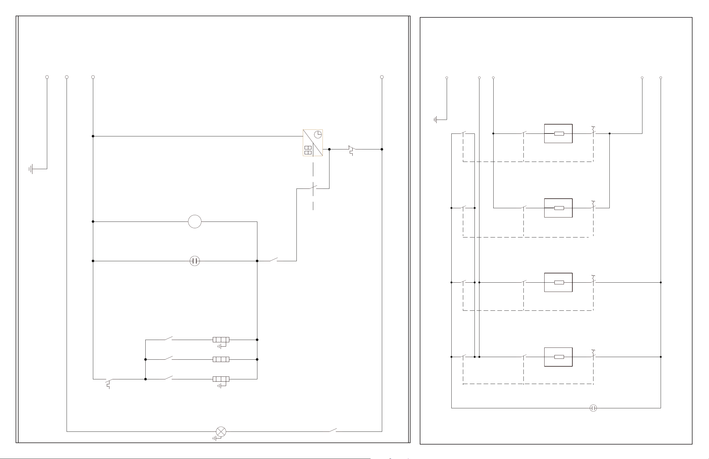
OVEN CONTROL/CONTROL DE HORNO
SURFACE CONTROL/CONTROL DE SUPERFICIE
PE
PE
N
-
L2
Cooling Fan
Ventilador
PE
PE
L1
r32
2
S1
S2
S2
S1
P1
P1
2
r31
2
2
a32
4
4
a31
4
P2
4
P2
L2
.
L1
limitador de seguridad
2
safety limitor
1
f2
h11
N
L/8
1
M
~
1
2
8a
.
termostato de trabajo
work thermostat
2
1
f1
P2
th.signallamp
a7
P1
a7
P1
a7
2
1
parrilla
bottom
2
fondo
4
parte superior
grill
top
1
r14
2
r8
2
r7
2
a7
5
1
1
1
P3
r34
S2
S1
S2
S1
2
P1
P1
2
r33
2
2
a34
4
4
a33
4
P2
4
P2
1
2
oven lamp
luz del horno
h4
L
N
 Loading...